Shortcut Key of AutoCAD
Autodesk Plant Solutions AutoCAD Plant 3D性能优化指南说明书
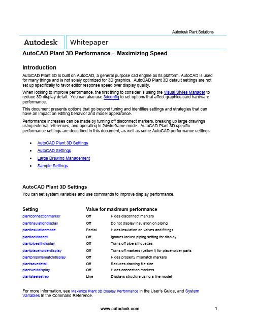
Autodesk Plant Solutions WhitepaperAutoCAD Plant 3D Performance – Maximizing SpeedIntroductionAutoCAD Plant 3D is built on AutoCAD, a general purpose cad engine as its platform. AutoCAD is used for many things and is not solely optimized for 3D graphics. AutoCAD Plant 3D default settings are not set up specifically to favor editor response speed over display quality.When looking to improve performance, the first thing to consider is using the Visual Styles Manager to reduce 3D display detail. You can also use 3dconfig to set options that affect graphics card hardware performance.This document presents options that go beyond tuning and identifies settings and strategies that can have an impact on editing behavior and model appearance.Performance increases can be made by turning off disconnect markers, breaking up large drawings using external references, and operating in 2dwireframe mode. AutoCAD Plant 3D specific performance settings are described in this document, as well as some AutoCAD performance settings.∙AutoCAD Plant 3D Settings∙AutoCAD Settings∙Large Drawing Management∙Sample SettingsAutoCAD Plant 3D SettingsYou can set system variables and use commands to improve display performance.Setting Value for maximum performanceplantconnectionmarker Off Hides disconnect markersplantinsulationdisplay Off Do not display insulation on pipingplantinsulationmode Partial Hides insulation on valves and fittingsplantlockfadectl Off Ignores locked piping setting for display plantpipesilhdisplay Off Turns off pipe silhouettesplantplaceholderdisplay Off Turns off markers (yellow !) for placeholder parts plantpropmismatchdisplay Off Hides property mismatch markersplantsavedetail Off Reduces drawing file sizeplantwelddisplay Off Hides connection markersplantsteelsetrep Line Displays structure using a line modelFor more information, see Maximize Plant 3D Display Performance in the User’s Guide, and System Variables in the Command Reference.You can close AutoCAD Plant 3D palettes that you are not using when working in the model. For example, closing the Data Manager can improve performance, especially when editing. You can also close Project Manager to improve performance. For best results close the palette, do not Auto-Hide.AutoCAD SettingsThere is no single best AutoCAD setting for performance, because some settings are designed to disable features that you need to select and edit. In general, the settings identified here are intended to maximize browsing speed.The most significant choice is between 2D and 3D view modes. 2D modes can display 3D objects that look similar to 3D wireframe, but the modes use a significantly different redraw database. The 3D redraw database is designed for quality and response, but not scalability. In practical terms, this means that in 3D view modes, performance deteriorates faster as the model in the display gets larger. Changing to 2D wireframe with silhouettes off can significantly improve performance.dispsilh=0, isolines=4 dispsilh=1, Isolines=0If you turn off dispsilh to improve performance in wireframe, you should set isolines to 4. Piping also uses plantpipesilhdisplay, which displays silhouettes for tube segments when dispsilh is off.For more information, see Control the Visual Style of the Plant 3D Model.Below are some of the AutoCAD system variables you can use to improve performance.AutoCAD Setting Value for maximum performancedispsilh Off Do not display silhouette edgesisolines 4 The number of contour lines per surface on objectspickfirst Off Objects are selected after the commandviewres 1 Sets the smoothness of curved objects in a 2D view savetime Zero (0) Turn off autosavevscurrent2Dwireframe Sets the fastest display modevtenable 0 Turns off smooth view transitions customerinvolvementprogram Off Turns off activity loggingIt is important to understand the impact of these settings and consider that they could cause undesired behavior. For example, turning off pickfirst speeds up browsing, but it disables the select connected parts shortcut menu. Dragging in 2dwireframe can be slower than 3dwireframe. The best performance configuration depends on how you are working with the model. Setting a low viewres speeds up dragging in 2D mode. Facetres is a similar variable that affects 3D views.You can use vtoptions to set a fast transition speed, lower the performance (fps) threshold, or disable view transitions.Other settings that are not specific to display can be used. For example, you can freeze unused layers to improve performance, instead of turning a layer off.You can also turn off features that you do not use. For example, if you do not need the properties window open, consider closing it until needed. Tracking, dynamic input, and even grips can be turned off when not used.Large Drawing ManagementBreaking up larger drawings into smaller ones using external references can significantly improve performance. For example, you can place equipment, piping, and structure into different drawings and break up large drawings by area.Sample SettingsYou can copy and paste the table below into the Command window, or create and run a LSP file. Values are also provided to restore default settings.Performance settings:(command "plantconnectionmarker" "0")(command "plantinsulationdisplay" "0")(command "plantinsulationmode" "p")(setvar "plantpipesilhdisplay" 0)(setvar "plantpropmismatchdisplay" 0)(command "plantplaceholderdisplay" "0")(setvar "plantwelddisplay" 0)(setvar "plantlockfadectl" 0)(setvar "plantsavedetail" 0)(command "plantsteelsetrep" "L")(setvar "dispsilh" 0)(setvar "isolines" 4)(setvar "pickfirst" 0)(command "viewres" "y" 1)(setvar "savetime" 0)(command "vscurrent" "2dwireframe")(setvar "vtenable" 0)(if (/= (getvar "cipmode") 0) (prompt "\nRun customerinvolvementprogram to disable.")) Default settings:(command "plantconnectionmarker" "1")(command "plantinsulationdisplay" "1")(command "plantinsulationmode" "f")(setvar "plantpipesilhdisplay" 1)(command "plantplaceholderdisplay" "1")(setvar "plantsavedetail" 1)(setvar "dispsilh" 1)(setvar "isolines" 0)(setvar "pickfirst" 1)(command "viewres" "y" 1000)(setvar "savetime" 10)(setvar "vtenable" 3)(command "vscurrent" "realistic")Autodesk, Inc.111 McInnis ParkwaySan Rafael, CA 94903USAAutodesk [and other products] are either registered trademarks or trademarks of Autodesk, Inc., in the USA and other countries. All other brand names, product names, or trademarks belong to their respective holders.© 2010 Autodesk, Inc. All rights reserved.。
SolidWorks工程图初级详细教程

教程一生成如下所示工程图。
工程图包含多个视图、中心线、中心符号、以及尺寸。
打开: <安装目录>\samples\tutorial\30minute\pressure_plate.sldprt。
一. 生成新工程图(Creating a New Drawing)1. 单击标准工具栏上的从零件/装配体制作工程图,然后单击确定。
SolidWorks 生成工程图并开始放置模型视图的过程。
2. 单击标准工具栏上的选项。
3. 在系统选项标签上,选择工程图、显示样式。
4. 在在新视图中显示切边下选择移除以隐藏圆角化面之间的过渡边线,然后单击确定。
5. 在 PropertyManager 中:●在方向下选择 *上视。
●在选项下消除选择自动开始投影视图以阻止投影视图 PropertyManager 在您放置正交模型视图时自动开始。
●在显示样式下单击消除隐藏线。
6. 将指针移到图形区域,然后单击来放置视图。
7. 在 PropertyManager 中,单击。
二. 生成剖面视图(Creating a Section View)1. 单击工程图工具栏上的剖面视图。
2. 将指针移动到压力盘的外边线上,直到中心点出现。
3. 将指针移动到盘的中心点上面。
4. 单击来开始剖切线。
5. 将指针直接移动到盘之下。
6. 单击来结束剖切线。
7. 将指针移到右面来放置视图并单击来结束。
8. 在剖切线下选择反向以反转剖面视图的方向。
9. 单击。
三. 生成局部视图(Creating a Detail View)1. 单击工程图工具栏上的局部视图。
2. 在剖面视图上移动指针然后单击来放置局部圆的中心。
3. 移动指针来定义局部圆并单击来结束。
4. 移动指针来放置局部视图,然后单击来添加视图。
5. 单击标准工具栏上的保存。
6. 接受默认文件名称,然后单击保存。
7. 如果提示保存参考的模型也保存零件,单击是。
四. 生成等轴测视图(Creating an Isometric View)1. 单击工程图工具栏上的模型视图。
CAD实用技巧

CAD实用技巧CAD实用技巧在CAD中怎么标弧长?1、用Li命令查询弧长;2、用DAN命令标注为角度;3、用ED命令将角度值编辑为弧长。
只要AutoCAD提示你选择物体,你都可这样干!(选择集设置):(1)直接点取方式:用鼠标直接点取所需图形;(2)窗口方式:从左到右(包含)、从右到左(包含及相交);(3)组方式:在“选择物体”提示下键入(G),注:选择此操作必须先给被选择对象编组;(4)前一方式:将前一操作选择对象作为当前选择集,在“选择物体”提示下键入(P);(5)最后方式:将最后一次绘制的图形对象作为当前选择集,在“选择物体”提示下键入(L);(6)全部方式:将当前图形中所见图形对象作为当前选择集,在“选择物体”提示下键入(A);(7)不规则窗口方式:在“选择物体”提示下键入(WP),构造一个不规则窗口框选所包含图形;(8)不规则交叉窗口方式:在“选择物体”提示下键入(CP),框选所包含及以之相交的图形;(9)围线方式:在“选择物体”提示下键入(F),以连线方式选取以之相交的图形;(10)扣除模式:从多个被选择图形的加入模式下,键入(R),点取将扣除的部分图形退出选择集;(11)返回到加入方式:在扣除模式下,键入(A),将扣除模式下返回到加入模式下;(12)交替选择对象:按下“Ctrl”键(首次点选后松开),交替选中重叠图形的所需图形后,回车确认。
平方米的表示输入M2^,然后选中2和^,再点击堆叠命令图标(a/b)查询全部闭合面积先建立面域(用ergion命令)将闭合图形建立成一个面域然后用massprop查询此面域,就有面积这一项CAD大考场(1)随着“CAD社区”的正式开版,我们每期会列出问题。
当然,你也可以将你在CAD工作中,和CAD学习中遇到的问题,让我们共同来建设好这个大考场。
考题一:工程技术人员在绘图时经常要在AutoCAD中输入上下标,对于下标的输入比较简单,只要使用“多行文本命令”,把需要设为下标的文字的字高改小一些就可以了。
autocad命令快捷键(AutoCADcommandshortcutkey)

autocad命令快捷键(AutoCAD command shortcut key)AutoCAD shortcut keyShortcut keys to execute command instructions3A 3DARRAY 3D array3DO 3DORBIT 3D Dynamic Observer3F 3DFACE 3D surface3P 3DPOLY 3D polylineA ARC arcADC ADCENTER AutoCAD design and Design CenterAA AREA areaAL ALIGN alignment (for 2D and 3D)AP APPLOAD loading and uninstalling applicationsAR ARRAY array*AR *ARRAY command arrayThe properties of ATT ATTDEF blockThe properties of *ATT *ATTDEF command blockATE ATTEDIT editing propertiesATE *ATTEDIT command type editing attributesATTE *ATTEDIT command type editing attributesB BLOCK dialog block buildingConstruction of *B *BLOCK command blockBH BHATCH dialog drawing pattern fillingBO BOUNDARY dialog box closed boundary establishment Establishment of *BO *BOUNDARY command type closed boundary BR BREAK interruptsC CIRCLE circleCHA PROPERTIES dialog type object special modification Modification of command type characteristics of *CH CHANGE CHA CHAMFER chamferDialog box color setting in COL COLCRDialog box color setting in COLOUR COLCRCO COPY replicationD DIMSTYLE size style settingDAL DIMALIGNED aligned linear annotationDAN DIMANGULAR angle annotationBaseline annotation of DBA DIMBASELINEDBC DBCONNECT provides an interface to an external database tableDCE DIMCENTER center markDCO DIMCONTINUE continuous taggingDDA DIMDISASSOCIATE annotation not associatedDDI DIMDIAMETER diameter markingDimension modification of DED DIMEDITMeasuring distance between two points by DI DISTDIV, DIVIDE and other distribution pointsDLI DIMLINEAR linear annotationDO DONUT double circlesDOR DIMORDIMATE coordinate taggingDOV DIMOVERRIDE update annotation variablesDR DRAWORDER display orderDRA DIMRADIUS radius labelingDRE DIMREASSOCIATE annotation AssociationDS DSETTINGS capture settingsDST DIMSTYLE size style settingDT DTEXT writes to textDV DVIEW defines parallel projection or perspective projection viewDeleting objects from E ERASEED DDEDIT single line text modificationEL ELLIPSE ellipseEX EXTEND extensionEXIT QUIT exitEXP EXPORT output fileEXT EXTRUDE will be stretched to three, Vivian two-dimensionalobject entityF FILLET filletFI FILTER filterDialog box selection settings for G GROUP *G *GROUP command set selectionGR DDGRIPS pinch control settingsH BHATCH dialog drawing pattern filling *H HATCH command drawing pattern filling HE HATCHEDIT editing pattern fillHI HIDE blankingI INSERT dialog insert block*I *INSERT command insert blockIAD IMAGEADJUST image adjustmentIAT IMAGEATTACH incorporated into images ICL IMAGECLIP capture imagesIM IMAGE dialog type attached image*IM *IMAGE command attached imageIMP IMPORT input fileIN INTERSECT creates intersecting entities or face fields INF IMTERFERE creates a 3D entity from a common partIO INSERTOBJ insertion objectL LINE draw linesLA LAYER dialog layer control*LA *LAYER command layer controlLE QLEADER boot line taggingLength of LRN LENGTHENLI LIST query object fileLINEWEIGHT LWEIGHT linewidthLO *LAYOUT configuration settingsLS LIST query object fileLT LINETYPE dialog type linear loading*LT *LINETYPE command linear loadingLTYPE LINETYPE dialog type linear loading*LTYPE *LINETYPE command linear loading Setting linear scaling factor in LTS LTSCALE LW lweight线宽设定我把搬移对象对象特性复制MA特性匹配我量测等距布点测量我的镜子镜像对象ML复线绘制多线钼的性质对象特性修改MS点个人空间从图纸空间转换支模型空间MT MTEXT多行文字写入实体化视图浮动视口MV偏移量偏移复制poptions选项OP轨道3dorbit三维动态观察器OS的捕捉对话框式对象捕捉设定*操作系统*捕捉命令式对象捕捉设定P潘即时平移* P *潘两点式平移控制选择性粘贴PA选择性粘贴partialopen *选择性粘贴将指定的对象加载对新图形中体育编辑编辑多义线绘制多义线发光性宝点绘制点绘制正多边型POL多边形公关方案选项prclose propertiesclose关闭对象特性修改对话框对象特性修改道具属性输出预览前预览打印图打印输出PS PSPACE图线空间publishtiweb发送支网页PTWPU清除肃清无用对象*浦*清洗命令式肃清无用对象r重绘重绘RA redrawall所有视口重绘重新重新生成意regenall所有视口重新生成REC矩形绘制矩形注册区域三维面域任rebame对话框式重命名*人* rebame命令式重命名Rev旋转利用绕轴旋转二维对象创建三维体RM ddrmodes打印辅助设定旋转RO旋转RPR rpref设置渲染参考渲染RR渲染伸展拉伸比例缩放比例尺调入剧本文件SCR脚本硒dsettings捕捉设定SEC检测通过使平面与实体相交创建面域集设定变量值setvar沙影着色SL层用平面剖切实体锡扣捕捉控制所以固体填实的三边形或四边形SP seell拼字SPL样条样条曲线SPE splinedit编辑样条曲线ST字型设定苏减差集运算T多行文字对话框式多行文字写入* T * MTEXT命令式多行文字写入钽片数字化仪规划厚度TH厚度钛图线空间和模型空间设定切换平铺模式工具栏的工具栏设定形位公差标注公差符号标注Tor的环面圆环修剪TR修剪UC dducs用户坐标系UCP dducsp设置正交窗口联合国部队对话框式单位设定*不*单位命令式单位设定大学联盟并集运算查看对话框式视图控制* V *查看视图控制ddvpopint视点VP*命令式视点VP的角度出发W WBLOCK对话框式图块写出*宽*图块命令式图块写出我们三维楔体楔爆炸分解XXA xattach贴附外部参考XB XBIND并入外部参考* b * XBIND命令式并入外部参考XC xclip截取外部参考XL参照线构造线XR XREF对话框式外部参考控制* *代替命令式外部参考控制XRz缩放视口缩入控制按Ctrl +编组按Ctrl + B捕捉按Ctrl + C复制按Ctrl + D坐标按Ctrl + E等轴测平面按Ctrl + F对象捕捉按Ctrl + G删格按Ctrl + J Ctrl + Shift + S图形另存为Ctrl + K超级链接我正交LCtrl +按Ctrl + M帮助按Ctrl + N新建Ctrl + O打开CTRL+P printingCTRL+Q exitCTRL+S preservationCTRL+T digitizerCTRL+U CTRL+F10 polar axisCTRL+V pasteCTRL+W object trackingCTRL+X shearCTRL+z returnsCTRL+1 object characteristicsCTRL+2 CAD Design CenterCTRL+6 data sourceCTRL+F6 toggles the current windowCTRL+F8 running partsCTRL+SHIFT+C replication with base point Shortcut keys to execute command instructions 3A 3DARRAY 3D array3DO 3DORBIT 3D Dynamic Observer3F 3DFACE 3D surface3P 3DPOLY 3D polylineA ARC arcADC ADCENTER AutoCAD design and Design Center AA AREA areaAL ALIGN alignment (for 2D and 3D)AP APPLOAD loading and uninstalling applications AR ARRAY array*AR *ARRAY command arrayThe properties of ATT ATTDEF blockThe properties of *ATT *ATTDEF command block ATE ATTEDIT editing propertiesATE *ATTEDIT command type editing attributes ATTE *ATTEDIT command type editing attributesB BLOCK dialog block buildingConstruction of *B *BLOCK command blockBH BHATCH dialog drawing pattern fillingBO BOUNDARY dialog box closed boundary establishment Establishment of *BO *BOUNDARY command type closed boundary BR BREAK interruptsC CIRCLE circleCHA PROPERTIES dialog type object special modification Modification of command type characteristics of *CH CHANGE CHA CHAMFER chamferDialog box color setting in COL COLCRDialog box color setting in COLOUR COLCRCO COPY replicationD DIMSTYLE size style settingDAL DIMALIGNED aligned linear annotationDAN DIMANGULAR angle annotationBaseline annotation of DBA DIMBASELINEDBC DBCONNECT provides an interface to an external database tableDCE DIMCENTER center markDCO DIMCONTINUE continuous taggingDDA DIMDISASSOCIATE annotation not associatedDDI DIMDIAMETER diameter markingDimension modification of DED DIMEDITMeasuring distance between two points by DI DISTDIV, DIVIDE and other distribution pointsDLI DIMLINEAR linear annotationDO DONUT double circlesDOR DIMORDIMATE coordinate taggingDOV DIMOVERRIDE update annotation variablesDR DRAWORDER display orderDRA DIMRADIUS radius labelingDRE DIMREASSOCIATE annotation AssociationDS DSETTINGS capture settingsDST DIMSTYLE size style settingDT DTEXT writes to textDV DVIEW defines parallel projection or perspective projection viewDeleting objects from E ERASEED DDEDIT single line text modificationEL ELLIPSE ellipseEX EXTEND extensionEXIT QUIT exitEXP EXPORT output fileEXT EXTRUDE stretches 2D objects to three and dimensionsF FILLET filletFI FILTER filterDialog box selection settings for G GROUP*G *GROUP command set selectionGR DDGRIPS pinch control settingsH BHATCH dialog drawing pattern filling*H HATCH command drawing pattern fillingHE HATCHEDIT editing pattern fillHI HIDE blankingI INSERT dialog insert block*I *INSERT command insert blockIAD IMAGEADJUST image adjustmentIAT IMAGEATTACH incorporated into imagesICL IMAGECLIP capture imagesIM IMAGE dialog type attached image*IM *IMAGE command attached imageIMP IMPORT input fileIN INTERSECT creates intersecting entities or face fields INF IMTERFERE creates a 3D entity from a common partIO INSERTOBJ insertion objectL LINE draw linesLA LAYER dialog layer control*LA *LAYER command layer control LE QLEADER boot line tagging Length of LRN LENGTHEN李查询对象文件列表lweight线宽线宽罗*布局配置设定ls列出查询对象文件LT线型对话框式线型加载*我*线型命令式线型加载对话框式线型加载线型线型*总*线型命令式线型加载它的所有设置线型比例因子LW lweight线宽设定我把搬移对象对象特性复制MA特性匹配我量测等距布点测量我的镜子镜像对象ML复线绘制多线钼的性质对象特性修改MS点个人空间从图纸空间转换支模型空间MT MTEXT多行文字写入实体化视图浮动视口MV偏移量偏移复制poptions选项OP轨道3dorbit三维动态观察器OS的捕捉对话框式对象捕捉设定*操作系统*捕捉命令式对象捕捉设定P潘即时平移* P *潘两点式平移控制选择性粘贴PA选择性粘贴partialopen *选择性粘贴将指定的对象加载对新图形中体育编辑编辑多义线绘制多义线发光性宝点绘制点绘制正多边型POL多边形公关方案选项prclose propertiesclose关闭对象特性修改对话框对象特性修改道具属性输出预览前预览打印图打印输出PS PSPACE图线空间publishtiweb发送支网页PTWPU清除肃清无用对象*浦*清洗命令式肃清无用对象r重绘重绘RA redrawall所有视口重绘重新重新生成意regenall所有视口重新生成REC矩形绘制矩形注册区域三维面域任rebame对话框式重命名*人* rebame命令式重命名Rev旋转利用绕轴旋转二维对象创建三维体RM ddrmodes打印辅助设定旋转RO旋转RPR rpref设置渲染参考渲染RR渲染伸展拉伸比例缩放比例尺调入剧本文件SCR脚本硒dsettings捕捉设定SEC检测通过使平面与实体相交创建面域集设定变量值setvar沙影着色SL层用平面剖切实体锡扣捕捉控制所以固体填实的三边形或四边形SP seell拼字SPL样条样条曲线SPE splinedit编辑样条曲线ST字型设定苏减差集运算T多行文字对话框式多行文字写入* T * MTEXT命令式多行文字写入钽片数字化仪规划厚度TH厚度钛图线空间和模型空间设定切换平铺模式工具栏的工具栏设定形位公差标注公差符号标注Tor的环面圆环修剪TR修剪UC dducs用户坐标系UCP dducsp设置正交窗口联合国部队对话框式单位设定*不*单位命令式单位设定大学联盟并集运算查看对话框式视图控制* V *查看视图控制ddvpopint视点VP*命令式视点VP的角度出发W WBLOCK对话框式图块写出*宽*图块命令式图块写出我们三维楔体楔爆炸分解XXA xattach贴附外部参考XB XBIND并入外部参考* b * XBIND命令式并入外部参考XC xclip截取外部参考XL参照线构造线XR XREF对话框式外部参考控制* * xref 命令式外部参考控制 xr z zoom 视口缩入控制ctrl + a 编组ctrl + b 捕捉ctrl + c 复制ctrl + d 坐标ctrl + e 等轴测平面ctrl + f 对象捕捉删格 ctrl + gctrl + j (ctrl + shift + n 图形另存为ctrl + k 超级链接正交 lctrl + lctrl + m 帮助ctrl + n 新建ctrl + o 打开ctrl + p 打印ctrl + q 退出ctrl + s 保存ctrl + t 数字化仪ctrl + ctrl + f10 极轴.ctrl + v 粘贴ctrl + w 对象跟踪ctrl + x 剪切ctrl + z 退回ctrl + 1 对象特性ctrl + 2 cad设计中心ctrl + 数据源ctrl + f6 切换当前窗口ctrl + f8 运行部件ctrl + shift + c 带基点复制 [/ color.2008 - 10 - 10: 21 03 张大水 (http: / / ) 获取帮助 f1.实现作图窗和文本窗口的切换 f2.控制是否实现对象自动捕捉 f3.数字化仪控制 f4.等轴测平面切换 f5.控制状态行上坐标的显示方式 f6.栅格显示模式控制 f7.正交模式控制 f8.栅格捕捉模式控制 f9.极轴模式控制 f10.对象追踪式控制 f11.ctrl + b: 栅格捕捉模式控制 (f9)刚刚看了一下半径标注 dra.直径标注 ddi.对齐标注 dal.dan: 角度标注ctrl + c: 将选择的对象复制到剪切板上ctrl + f: 控制是否实现对象自动捕捉 (f3) ctrl + g: 栅格显示模式控制 (f7)ctrl + j: 重复执行上一步命令ctrl + k, 超级链接ctrl + n: 新建图形文件ctrl + d: 打开选项对话框aa: 测量区域和周长 (area)al: 对齐 (align)ar: 阵列 (array)ps: 加载 * lsp程系w: 打开视图对话框 (dsviewer) 打开对相自动捕捉对话框 are: st: 打开字体设置对话框 (style) so, 绘制二围面 (2d solid.ps: 拼音的校核 (spell)sc: 缩放比例 (scale)sn: 栅格捕捉模式设置 (snap) the 文本的设置 (dtext).测量两点间的距离).where 插入外部对相打开特性对话框 ctrl + 1.打开图象资源管理器 ctrl + 2.打开图象数据原子 ctrl + 6.ctrl + o: 打开图象文件ctrl + p: 打开打印对说框ctrl + s: 保存文件ctrl + u: 极轴模式控制 (f10) ctrl + v: 粘贴剪贴板上的内容ctrl + w: 对象追踪式控制 (f11) ctrl + x: 剪切所选择的内容ctrl + y: 重做ctrl + z: 取消前一步的操作a: 绘圆弧b: 定义块c: 画圆d: 尺寸资源管理器e: 删除f: 倒圆角g: 对相组合h: 填充i 插入s: 拉伸文本输入.w: 定义块并保存到硬盘中the 直线m: 移动x: 炸开v: 设置当前坐标the 恢复上一次操做o: 偏移p: 移动z: 缩放Display degraded adapter (switch) [O]To adapt to the grid point perspective [Shift] + [Ctrl] + [A] Arrange [Alt] + [A]Angle capture (switch) [A]Animation mode (switch) [N]Change to rear view [K]Background lockout (switch) [Alt] + [Ctrl] + [B]Unit 1Next time unit [...]Change to the upper (Top) view [T]Change to the end (Bottom) view [B]Change to camera (Camera) view [C]Change to the front (Front) view [F]Change to equal user (User) view [U]Change to the right (Right) view [R]Change to perspective (Perspective) diagram [P] Cycle change selection method [Ctrl] + [F]Default light (switch) [Ctrl] + [L]Delete objects [DEL]The current view is temporarily invalid [D]Display geometry inside frame (switch) [Ctrl] + [E] Show the first toolbar [Alt] + [1]Expert mode ? full screen (switch) [Ctrl] + [X] Temporary (Hold) scene [Alt] + [Ctrl] + [H] Retrieve (Fetch) scene [Alt] + [Ctrl] + [F]Freeze selected objects [6]Skip to the last frame [END]Skip to the first frame [HOME]Display / hide camera (Cameras) [Shift] + [C]Display / hide geometry (Geometry) [Shift] + [O]Display / Hide Grid (Grids) [G]Show / hide help (Helpers) objects [Shift] + [H]Display / hidden light source (Lights) [Shift] + [L] Display / hide particle system (Particle Systems) [Shift] + [P] Display / hide Space Warps objects [Shift] + [W]Lock user interface (switch) [Alt] + [0]Match to camera (Camera) view [Ctrl] + [C]Material editor (Material) [M]Maximize the current view (switch) [W]Script editor [F11]New scene [Ctrl] + [N]Normal (Normal) alignment [Alt] + [N]Push down grid small keyboard [-]To nudge grid [+] small keyboardNURBS surface display mode [Alt] + [L] or [Ctrl] + [4] NURBS adjust grid 1 [Ctrl] + [1]NURBS adjust grid 2 [Ctrl] + [2]NURBS adjust grid 3 [Ctrl] + [3]Offset capture [Alt] + [Ctrl] + [spaces]Open a MAX file [Ctrl] + [O]Translation view [Ctrl] + [P]Interactive translation view [I]Place high light (Highlight) [Ctrl] + [H]Play / Stop Animation [/]Fast (Quick) rendering [Shift] + [Q]Go back to the previous scene * [Ctrl] + [A]Go back to the previous view * to make [Shift] + [A] Undo scene * [Ctrl] + [Z]Undo view * Act [Shift] + [Z]Refresh all views [1]Render with the previous parameter [Shift] + [E] or [F9] Rendering configuration [Shift] + [R] or [F10]Loop changes in xy/yz/zx lock [F8]Bound to the X axis [F5]Bound to the Y axis [F6]Bound to the Z axis [F7]Rotate (Rotate) view mode [Ctrl] + [R] or [V]Save (Save) file [Ctrl] + [S]Transparent display of selected objects (switches) [Alt] + [X] Select parent object [PageUp]Select sub objects [PageDown]Select objects according to the name [H]Select lock (switch) [space]Reduce the surface of the selected object (switch) [F2] Show all view grids (Grids) (switches) [Shift] + [G]Show / hide Command Panel [3]Show / hide floating toolbar [4]A picture that shows the last rendering [Ctrl] + [I]Show / hide the main toolbar [Alt] + [6]Display / hide security box [Shift] + [F]* display / hide the bracket of the selected object [J] Display / hide toolbar [Y] / [2]Percentage (Percent) capture (switch) [Shift] + [Ctrl] + [P] Open / close capture (Snap) [S]Loop through capture point [Alt] + spaceSound (switch)Spacer placed objects [Shift] + [I]Change to light view [Shift] + [4]Loop change sub object hierarchy [Ins]Sub object selection (switch) [Ctrl] + [B]Map material (Texture) amendment [Ctrl] + [T]Increase dynamic coordinates [+]Reduce dynamic coordinates [-]Activate dynamic coordinates (switches) [X]Precise input transition [F12]All thawed [7]Show hidden objects according to name [5]Refresh the background image (Background) [Alt] + [Shift] + [Ctrl] + [B]Display geometry frame (switch) [F4]View background (Background) [Alt] + [B]B (Box) fast explicit geometry (switch) [Shift] + [+]Open the virtual reality digital keyboard [1]Virtual view moves down the numeric keypad [2]Move the digital keyboard to the left of the virtual view [4]The virtual view moves the numeric keypad right [6]Move the virtual view to the digital keyboard [8]Virtual view magnify digital keyboard [7]Virtual view reduces digital keyboard [9]Real color display geometry (switch) [F3] in sceneAll views display all objects [Shift] + [Ctrl] + [Z]* window zoom to select object range (Extents) [E] Zoom range [Alt] + [Ctrl] + [Z]Windows zoom two times [Shift] + numeric keyboard [+] Magnifier tool [Z]Windows shrink two times [Shift] + numeric keyboard [-] Zoom in according to frame selection [Ctrl] + [w] Windows interactive zoom [Windows interactive narrowing []Trajectory viewJoin (Add) key frame [A]The first time unit [<]Next time unit [>]Edit (Edit) key frame mode [E]Edit zone mode [F3]Edit time pattern [F2]Expanded object (Object) switch [O] Deployment trajectory (Track) switching [T] Function (Function) curve model [F5] or [F] Lock the selected object [spaces][key] to display on mobile highlightMoving down arrows highlight []The left shift key frame [left] lightMove the key frame to the right lightly Location region model [F4]Go back to the previous scene * [Ctrl] + [A] Undo scene * [Ctrl] + [Z]Render with the previous configuration [F9]Rendering configuration [F10]Shut down [Ctrl] + [down]To furl [Ctrl] + [up]material editorRender with the previous configuration [F9] Rendering configuration [F10]Undo scene * [Ctrl] + [Z]Schematic (Schematic) viewNext time unit [>]The first time unit [<]Go back to the previous scene * [Ctrl] + [A] Undo scene * [Ctrl] + [Z]Active ShadeDraw (Draw) region [D]Rendering (Render) [R]Lock toolbar (dock window) [space]Video editingJoin the filter (Filter) project [Ctrl] + [F] Add the input (Input) item [Ctrl] + [I]Add the layer (Layer) item [Ctrl] + [L]Add output (Output) item [Ctrl] + [O]Join (Add) new project [Ctrl] + [A]Join scene (Scene) event [Ctrl] + [S]Edit (Edit) current events [Ctrl] + [E] Execution (Run) sequence [Ctrl] + [R]New (New) sequence [Ctrl] + [N]Undo scene * [Ctrl] + [Z]NURBS editingCV constraint normal (Normal) move [Alt] + [N] CV bound to U to move [Alt] + [U]CV bound to V to move [Alt] + [V]Display curve (Curves) [Shift] + [Ctrl] + [C]Display control point (Dependents) [Ctrl] + [D]The display lattice (Lattices) [Ctrl] + [L]NURBS surface display mode switching [Alt] + [L]Display surfaces (Surfaces) [Shift] + [Ctrl] + [S]Display toolbox (Toolbox) [Ctrl] + [T]The surface is neat (Trims) [Shift] + [Ctrl] + [T]Select the sub level of the object [Ctrl] + [H] according to the nameLock the selected object [space] of 2DSelect the next point of the U direction [Ctrl] +Select V to the next point of [Ctrl] + [up]Select U to the previous point [Ctrl] + [left]Select V to the previous point [Ctrl] + [down]Select sub objects [H] by nameSoft selection of objects [Ctrl] + [S]Convert to Curve CV hierarchy [Alt] + [Shift] + [Z] Convert to Curve hierarchy [Alt] + [Shift] + [C] Convert to Imports hierarchy [Alt] + [Shift] + [I] Convert to Point hierarchy [Alt] + [Shift] + [P] Convert to Surface CV hierarchy [Alt] + [Shift] + [V] Convert to Surface hierarchy [Alt] + [Shift] + [S] Convert to the previous level [Alt] + [Shift] + [T] Conversion downgrade [Ctrl] + [X]FFDSwitch to Point (Control) level [Alt] + [Shift] + [C]To the lattice (Lattice) hierarchy [Alt] + [Shift] + [L] To set the volume (Volume) level [Alt] + [Shift] + [S] Convert to the upper level [Alt] + [Shift] + [T]Open UVW mapEnter edit (Edit) UVW mode [Ctrl] + [E]Call *UVW file [Alt] + [Shift] + [Ctrl] + [L]Save UVW files in *.uvw format [Alt] + [Shift] + [Ctrl] + [S]Interrupt (Break) selection point [Ctrl] + [B]Separation (Detach) boundary point [Ctrl] + [D]Filter selection surface [Ctrl] + [spaces]Horizontal flip [Alt] + [Shift] + [Ctrl] + [B]Vertical (Vertical) flip [Alt] + [Shift] + [Ctrl] + [V]Freeze (Ctrl) + [F]Hide (Ctrl) + [H]All thawed (unFreeze) [Alt] + [F]Alt (unHide) + HGet the surface selections from the stack [Alt] + [Shift] + [Ctrl] + [F]Get selected works from the surface [Alt] + [Shift] + [Ctrl] + [V]Lock the selected vertices [spaces]Mirroring the level of [Alt] + [Shift] + [Ctrl] + [N] Vertical mirror [Alt] + [Shift] + [Ctrl] + [M]Horizontal move [Alt] + [Shift] + [Ctrl] + [J]Vertical move [Alt] + [Shift] + [Ctrl] + [K]Translation view [Ctrl] + [P]Pixel capture [S]Plane map surface / reset UVW [Alt] + [Shift] + [Ctrl] + [R] Horizontal scaling [Alt] + [Shift] + [Ctrl] + [I]Vertical scaling [Alt] + [Shift] + [Ctrl] + [O]Moving material dots [Q]Rotate material dots [W]Equal scaling material dots [E]Welding (Weld) selected material points [Alt] + [Ctrl] + [W] Weld (Weld) to the target material point [Ctrl] + [W]The option of Unwrap (Options) [Ctrl] + [O]Update map (Map) [Alt] + [Shift] + [Ctrl] + [M]Extend the Unwrap view to all display [Alt] + [Ctrl] + [Z]Frame select zoom Unwrap view [Ctrl] + [Z]Extend the Unwrap view to the size of the selected material points [Alt] + [Shift] + [Ctrl] + [Z]Zoom to Gizmo size [Shift] + [spaces]Zoom (Zoom) tool [Z]Reactor (Reactor)The establishment of (Create) reaction (Reaction) [Alt] + [Ctrl] + [C]Delete (Delete) reaction (Reaction) [Alt] + [Ctrl] + [D]Edit status (State) switch [Alt] + [Ctrl] + [S]Set maximum effect (Influence) [Ctrl] + [I]Set minimum influence (Influence) [Alt] + [I]Set influence value (Value) [Alt] + [Ctrl] + [V]ActiveShade (Scanline)Initialization [P]Update [U]macro editor Cumulative counter [Q]。
AutoCAD制图词汇2

AutoCAD制图词汇2QDIM 快速标注快速标注qsave 快存快速存档qtext 快速文字快速文字Quadratic 二次二次quality 质量品质Quick Tour 快速指南快速导览radian 弧度弪度Radio Button 单选钮圆钮radius 半径半径raster file format 光栅文件格式网格档案格式Raster Image 光栅图像网格式影像raster image boundaries 光栅图像边界网格式影像边界ray 射线射线, 光线Ray Casting 射线法raytraced renderer 光线跟踪渲染光线追踪彩现raytraced shadows 光线跟踪阴影光线追踪阴影read 读取读取Realtime 实时即时模式recover 恢复修复recover 修复修复rectang 矩形矩形recursion 递归递回Redefine 重定义重新定义redo 重做重做redraw 重画重绘redrawall 全重画全部重绘reference 引用参考reference 参照参考reference angles 参考角参考角度reference point 参考点参考点refine 精度控制精细化reflection color 反射色反射色reflection mapping 反射贴图反射贴图refractive index 折射指数折射系数refresh 刷新更新regen 重生成重生regenall 全重生成全部重生regenauto 自动重生成自动重生regenerate 重生成重生regeneration 重生成重生region 面域面域registry 注册表登录reinit 重初始化重新起始设定reinstall 重新安装重新安装relative angles 相对角相对角度relative coordinates 相对坐标相对座标release 版本版本Reload 重载重新载入remove 删除移除rename 重命名更名rename 重命名更名render 渲染彩现renderer 渲染程序彩现程式Replace 替换取代replay 重放重播Requirement 需求需求reset 重置重设resizing 改变大小重新调整尺寸resolution 融入解析度resolution 分辨率解析度restore 恢复取回resume 恢复执行继续执行Retain 保留保留return button 回车键 Enter 键revert 复原恢复原状revolve 旋转回转revsurf 旋转曲面回转曲面ridge 棱脊线Right-Angle 直角直角rmat 材质彩现材质rollback 回卷溯回root point 原点根点rotate 旋转旋转rotate3d 三维旋转旋转 3DRotation 旋转旋转routine 例行程序常式Rows dialog box "行"对话框列对话方块rpref 渲染选项彩现环境设定rscript 重复执行重新执行脚本rubber-band line 拖引线伸缩线rulesurf 直纹曲面规则曲面Run Script 运行脚本执行脚本running object snap 执行对象捕捉常驻式「物件锁点」running override 整体替代整体取代runout 跳动偏转度sample 样例取样Saturation 饱和度饱和度save 保存储存Save back 存回回存saveas 另存为另存新档saveimg 保存图像储存影像scale 比例缩放,(缩放)比例 if used as noun 调整比例, 比例scale factor 比例因子比例系数Scaled to Fit 按图纸空间缩放调整比例到布满scan 扫描扫描Scatter 散布图散量scene 场景场景schema 模式纲要schema 模式纲要screen 屏幕萤幕script 脚本脚本script files 脚本文件脚本档scroll bar 滚动条卷动轴SDI(MDI) 单文档界面(多文档界面)SE Isometric 东南等轴测东南等角SE Isometric 东南等轴测东南等角Search for Help on 搜索帮助寻找辅助说明主题section 区域,部分,节(相对于章节)剖面section 切割剖面section 截面剖面see 参见参阅segment 段,线段区段, 线段select 选择选取select all 全部选择全选Select object 对象选择选取物件selectable 可选择的可选取selection 选择集,选择选取,选项 (作名词用)selection sets 选择集选集Separate 分割分隔,个别的Separate 分割分隔,个别的Serial number 序列号序号session 任务阶段作业set 设置(v),集合(n) 设定setting 设置设定shade 着色,灰度(用于单色 Gray ) 描影shader 着色程序描影程式shadow map 阴影贴图阴影贴图shape 形造型Sharpness 尖锐度鲜明度sheet 表,板(for ACIS only) 图纸Shell 抽壳薄壳shell SHELL 薄壳Shell 抽壳薄壳shortcut 快捷键快显show 显示展示Silhouette 轮廓剪影Single Face 单一表面单面single-pen plotter 单笔式绘图仪单笔绘图机size 数目尺寸sizing 调整大小调整尺寸sketch 徒手画徒手描绘slice 剖切面(as n.) 切割面slice 剖切切割面slide 幻灯片幻灯片slide libraries 幻灯库幻灯片库smooth shading 平滑着色平滑描影smoothing angle 平滑角度平滑角度snap 捕捉锁点snap angle 捕捉角度锁点角度snap grid 捕捉栅格锁点格点Snap mode 捕捉模式锁点模式snap resolution 捕捉分辨率锁点解析度SnapTips 捕捉提示锁点提示solid 填充实体, 2D 实面solid (二维)填充/(三维)实体实体, 2D 实面Solid Fill 实体填充实面填实solid modeler 实体建模实体模型器solids 实体实体, 3D 实体sorting 排序排序source applications 源文件source point 源点来源点space 空间空间spacing 间距间距Special Edit 特定编辑特殊编辑specific 指定(的)特定的specific 特有的特定的specify 指定指定specular reflection 镜面反射(高光)镜面反射Spelling 拼写检查拼字sphere 球面圆球体spherical projection 球面投影球面投影spline 样条曲线云形线spline frame 样条曲线框架云形线架构splinedit 样条编辑云形线编辑Split 拆分分割spooler 缓冲(文件)排存器spotlight angles 聚光灯角度stack 堆栈堆叠Stack 堆叠堆叠stacked text 叠式文本堆叠文字stamp 戳记戳记Standard 标准标准Start 起点启动start angle 起点角度起始角度start tangent 起点切向起始切点Start Up dialog box "启动"对话框「启动」对话方块starting 起始起点statements 状态说明叙述,. 声明, 陈述式statistics 统计信息统计值stats 统计统计值status 状态状态stlout STL 输出汇出Stochastic 随机推测Stone Color 石质颜色石头颜色straighten 拉直拉直stretch 拉伸拉伸Strikeout Maybe 删去删除线style 样式字型substitute 替换替换subtract 差集减去Suffix 后缀字尾support directory 支持目录支援目录support files 支持文件支援档suppress 禁止抑制suppress 不输出抑制Suppress 收缩抑制surface 曲面表面, 曲面SW Isometric 西南等轴测西南等角SW Isometric 西南等轴测西南等角swap file 交换文件置换档swatch 样本样本sweep 延伸扫掠sweep 抹去扫掠sweep 扫掠扫掠switch 切换开关switch 开关开关swivel 旋转旋转swivel 旋转旋转sym 符号符号symbol set 符号集符号集symbol table 符号表符号表Symmetrical 对称对称Synchronize 同步同步system requirements 系统需求系统需求system variables 系统变量系统变数syswindows 系统窗口系统视窗。
修改CAD快捷键(ModifytheCADshortcutkey)

修改CAD快捷键(Modify the CAD shortcut key)循环W,*特性匹配e,*擦除r,*偏移量T * MTEXTa,*弧s,*刻度D、*区f,*行缩放x,*爆炸C,*副本V,*移动B,*休息镜子FA层QE,*编辑QF,*性属性SF,*样条XF,*艾吉尔ZZ,*旋转铬,*颜色大,*对齐标注英尺×圆角TT,*修剪DZ,*倒角De,物件TD,*爸爸EE,*扩展G * qselectQQ,*回复字体显示问号时,先输入FONTALT再输入宋体,或者输入”。
“或者“txt”注:更改CAD的快捷键只需更改CAD目录下的PGP文件ACAD。
对于cad2005,在菜单:工具--自定义--编辑自定义文件--程序参数(ACAD。
PGP)中更改来的方便些。
更改后,在不关闭软件的情况下,用勒命令初始化,使更改生效。
Q *圈(圆)W,*特性匹配(属性匹配)E、*擦除(删除)R *偏移(偏移)T * MTEXT(多行文本)一、*旋转(旋转)S,*规模(比例缩放)D、*区(标注)F、*线(直线)Z *变焦(视图缩放)X,*爆炸(分解)C、副本(复制)V *移动(对象移动)RR,*镜(镜像)FA,*层(图层操作)QE,*编辑(多段线编辑)QF,*条(多段线)QR,*(修改特性)SF,*样条(样条曲线)XF,*艾吉尔(射线)Cr,颜色(设置颜色)大,物件(直线标注)FT,*角(圆角)G *装饰(打断)DZ,*倒角(倒角)De *对齐标注(对齐标注)TD,*单行文字(单行文字)GG,*延长(延伸)DF(标注半径)直流,(标注直径)CAD的快捷键是提高了速度,但是我们基本上要用左手控制所有字母键盘,不太方便,我有一个方法,可以改变快捷键的参数,例如画直线是经常用的,但是快捷键是“L”,可以改为“大”,这样画直线就比较方便,可以用以下方法改变它,1、在”工具-自定义-编辑自定义文件-程序参数”。
2、在这个文本中把“我行”,把这个“L”改为自已方便“大”。
关于电机的毕业设计
关于电机的毕业设计【篇一:电机设计毕业论文】目录摘要 ....................................................................................................... .. (1)abstract ............................................................................................. . (1)第一章中小型电机设计概述 ....................................................................................................... . (2)1.1设计技术要求 ....................................................................................................... .. (2)1.2电机主要尺寸 ....................................................................................................... .. (2)1.3 绕组构及成原理 ....................................................................................................... (4)1.4主磁路 ....................................................................................................... .. (4)1.5电抗 ....................................................................................................... (6)1.6损耗与效率 ....................................................................................................... (7)1.7通风散热 ....................................................................................................... . (7)第二章三相异步电动机设计(y180l-6/15kw) (9)2.1电机主要尺寸及绕组设计 ....................................................................................................... (9)2.2电磁计算步骤与程序 ....................................................................................................... .. (9)第三章电机优化设计方案 ....................................................................................................... (28)3.1相关理论分析 ....................................................................................................... (28)3.2电磁调整方案 ....................................................................................................... (28)第四章 autocad简介及其绘图 ....................................................................................................... .. (30)4.1 autocad简介 ....................................................................................................... (30)4.2 autocad的基本功能 ....................................................................................................... (30)4.3 autocad绘图 ....................................................................................................... (31)总结 ....................................................................................................... . (32)参考文献: .................................................................................................... .. (32)附录(Ⅰ)外文资料原文及译文 ....................................................................................................... .. 34附录(Ⅱ)三设计方案结果 ....................................................................................................... . (39)三相鼠笼式异步电动机设计(y180l-6 /15kw)专业:电气工程极其自动化学号:02131107 学生姓名:刘常洲指导老师:肖倩华摘要异步电机是工农业生产中应用最广泛的电机。
autocad技巧

autocad技巧1.在AutoCAD中有时有交叉点标记在鼠标点击处产生,用BLIPMODE命令,在提示行下输入OFF可消除它。
2.有的用户使用AutoCAD时会发现命令中的对话框会变成提示行,如打印命令,控制它的是系统变量CMDDIA,关掉它就行了。
3.椭圆命令生成的椭圆是以多义线还是以椭圆为实体是由系统变量PELLIPSE决定,当其为1时,生成的椭圆是PLINE。
4.CMDECHO变量决定了命令行回显是否产生,其在程序执行中应设为0。
5.DIMSCALE决定了尺寸标注的比例,其值为整数,缺省为1,在图形有了一定比例缩放时应最好将其改为缩放比例。
6.BREAK将实体两点截开,在选取第二点时如用“@”来回答,可由第一点将实体分开。
7.CAD的较高版本中提供了形位公差标注,但圆度及同轴度中的圆不够圆,其实,AutoCAD中常见符号定义都在AutoCAD安装目录下SUPPORT子目录下的gdt.shp文件中,其中2号和4号字符定义了圆形的形状,圆的弧度竟为127°,但不太好改正之(如改为90°更不好看)。
8.空心汉字字形如使用AutoCAD R14中的BONUS功能(一定要完全安装AutoCAD,或自定义安装时选了它),有一个TXTEXP命令,可将文本炸为线,对做立体字十分有用。
9.AutoCAD R14的BONUS中有一个ARCTEXT命令,可实现弧形文本输出,使用方法为先选圆弧,再输入文本内容,按OK。
10.BONUS中还有一个有用的命令,即MPEDIT,用它将多个线一齐修改为多义线,再改它的线宽。
11.image命令在R14中代替了R13中的BMPIN、PCXIN之类命令,它将位图嵌入文件中,只用来显示,如炸开就成了空框架,如何使PCXIN等命令重现?请将R13安装目录下的RASTERIN.EXE拷入R14下,用appload将其装入,然后就可以将位图导入(可编缉,可炸开)了。
- 1、下载文档前请自行甄别文档内容的完整性,平台不提供额外的编辑、内容补充、找答案等附加服务。
- 2、"仅部分预览"的文档,不可在线预览部分如存在完整性等问题,可反馈申请退款(可完整预览的文档不适用该条件!)。
- 3、如文档侵犯您的权益,请联系客服反馈,我们会尽快为您处理(人工客服工作时间:9:00-18:30)。
Auto CAD快捷命令
Auto CAD快捷绘图命令PO, *POINT(点)
L, *LINE(直线)
XL, *XLINE(射线)
PL, *PLINE(多段线)
ML, *MLINE(多线)
SPL, *SPLINE(样条曲线)POL, *POLYGON(正多边形)REC, *RECTANGLE(矩形)C, *CIRCLE(圆)
A, *ARC(圆弧)
DO, *DONUT(圆环)
EL, *ELLIPSE(椭圆)REG, *REGION(面域)MT, *MTEXT(多行文本)T, *MTEXT(多行文本)
B, *BLOCK(块定义)
I, *INSERT(插入块)
W, *WBLOCK(定义块文件)DIV, *DIVIDE(等分)
H, *BHATCH(填充)Auto CAD快捷修改命令CO, *COPY(复制)
MI, *MIRROR(镜像)
AR, *ARRAY(阵列)
O, *OFFSET(偏移)
RO, *ROTATE(旋转)
M, *MOVE(移动)
E, DEL键 *ERASE(删除)X, *EXPLODE(分解)
TR, *TRIM(修剪)
EX, *EXTEND(延伸)
S, *STRETCH(拉伸)
LEN, *LENGTHEN(直线拉长)SC, *SCALE(比例缩放)
BR, *BREAK(打断)
CHA, *CHAMFER(倒角)
F, *FILLET(倒圆角)
PE, *PEDIT(多段线编辑)ED, *DDEDIT(修改文本)
Auto CAD快捷视窗缩放
P, *PAN(平移)
Z+空格+空格, *实时缩放
Auto CAD快捷尺寸标注
DLI, *DIMLINEAR(直线标注)DAL, *DIMALIGNED(对齐标注)DRA, *DIMRADIUS(半径标注)DAN, *DIMANGULAR(角度标注)DCE, *DIMCENTER(中心标注)DOR, *DIMORDINATE(点标注)Z, *局部放大
Z+P, *返回上一视图
Z+E, *显示全图
TOL, *TOLERANCE(标注形位公差)LE, *QLEADER(快速引出标注)DBA, *DIMBASELINE(基线标注)DCO, *DIMCONTINUE(连续标注)D, *DIMSTYLE(标注样式)
DED, *DIMEDIT(编辑标注)
DDI, *DIMDIAMETER(直径标注) DOV,
*DIMOVERRIDE(替换标注系统变量) AUTO CAD快捷键常见命令
ADC, *ADCENTER(设计中心“Ctrl+2”)CH, MO *PROPERTIES(修改特性“Ctrl+1”) MA, *MATCHPROP(属性匹配)
ST, *STYLE(文字样式)
COL, *COLOR(设置颜色)
LA, *LAYER(图层****作)
LT, *LINETYPE(线形)
LTS, *LTSCALE(线形比例)
LW, *LWEIGHT (线宽)
UN, *UNITS(图形单位)
ATT, *ATTDEF(属性定义)
ATE, *ATTEDIT(编辑属性)
BO, *BOUNDARY(边界创建,包括创建闭合多段线和面域)
AL, *ALIGN(对齐)
EXIT, *QUIT(退出)IMP, *IMPORT(输入文件)
OP,PR *OPTIONS(自定义CAD设置)PRINT, *PLOT(打印)
PU, *PURGE(清除**)
R, *REDRAW(重新生成)
REN, *RENAME(重命名)
SN, *SNAP(捕捉栅格)
DS, *DSETTINGS(设置极轴追踪)OS, *OSNAP(设置捕捉模式)
PRE, *PREVIEW(打印预览)
TO, *TOOLBAR(工具栏)
V, *VIEW(命名视图)
AA, *AREA(面积)
DI, *DIST(距离)
LI, *LIST(显示图形数据信息)EXP, *EXPORT(输出其它格式文件)
AUTO CAD快捷常用CTRL快捷键
【CTRL】+1 *PROPERTIES(修改特性) 【CTRL】+2 *ADCENTER(设计中心)【CTRL】+O *OPEN(打开文件)【CTRL】+N、M *NEW(新建文件)【CTRL】+P *PRINT(打印文件)【CTRL】+S *SA VE(保存文件)【CTRL】+Z *UNDO(放弃)【CTRL】+X *CUTCLIP(剪切) 0 【CTRL】+C *COPYCLIP(复制)【CTRL】+V *PASTECLIP(粘贴)【CTRL】+B *SNAP(栅格捕捉)【CTRL】+F *OSNAP(对象捕捉)【CTRL】+G *GRID(栅格)【CTRL】+L *ORTHO(正交)【CTRL】+W *(对象追踪)【CTRL】+U *(极轴)
(三)AUTO CAD快捷常用功能键
【F1】 *HELP(帮助)【F7】 *GRIP(栅格)【F8】 *ORTHO(正交)【F2】*(文本窗口)
【F3】 *OSNAP(对象捕捉)。