521-9248中文资料
汉文1004选修课程填报表 (1)
11 付涛涛 12 王利利 13 师秀秀 14 史鹏珍 15 呼凯亮 16 张晓春 17 强红瑞 18 南雪 19 20 21 22 23 24 程如 赵瑛 刘凯 徐静 陈焕 陈琳
25 遇婷婷 26 兰小娟 27 李远征 28 鲁元寿 29 孙铭言 30 呼延浩 31 王晓波 32 梁继花 33 雷倩 34 范艺璇
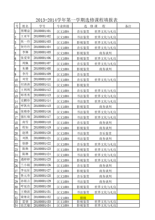
2013-2014学年第一学期选修课程填报表
序号 姓名 1 黑曙益 2 3 4 5 6 7 8 9 10 王亚军 焦一丹 贺丹丹 李琳 张爱荣 周佩 朱璐 李丹 刘莹 学号 20100001401 20100001402 20100001403 20100001404 20100001405 20100001406 20100001407 20100001408 20100001409 20100001410 20100001411 20100001412 20100001413 20100001414 20100001415 20100001416 20100001417 20100001418 20100001419 20100001420 20100001421 20100001422 20100001423 20100001424 20100001425 20100001426 20100001427 20100001428 20100001429 20100001430 20100001431 20100001432 20100001433 20100001434 专业班级 汉文1004 汉文1004 汉文1004 汉文1004 汉文1004 汉文1004 汉文1004 汉文1004 汉文1004 汉文1004 汉文1004 汉文1004 汉文1004 汉文1004 汉文1004 汉文1004 汉文1004 汉文1004 汉文1004 汉文1004 汉文1004 汉文1004 汉文1004 汉文1004 汉文1004 汉文1004 汉文1004 汉文1004 汉文1004 汉文1004 汉文1004 汉文1004 汉文1004 汉文1004 选 修 课 程 备注 音乐鉴赏 书法鉴赏 影视鉴赏 音乐鉴赏 影视鉴赏 影视鉴赏 音乐鉴赏 影视鉴赏 音乐鉴赏 音乐鉴赏 影视鉴赏 音乐鉴赏 书法鉴赏 书法鉴赏 影视鉴赏 书法鉴赏 书法鉴赏 音乐鉴赏 影视鉴赏 书法鉴赏 书法鉴赏 音乐鉴赏 影视鉴赏 书法鉴赏 影视鉴赏 音乐鉴赏 影视鉴赏 音乐鉴赏 书法鉴赏 影视鉴赏 书法鉴赏 留级 影视鉴赏 影视鉴赏 世界文化与礼仪 世界文化与礼仪 世界文化与礼仪 商务谈判 世界文化与礼仪 世界文化与礼仪 商务谈判 商务谈判 音乐鉴赏 商务谈判 世界文化与礼仪 世界文化与礼仪 世界文化与礼仪 世界文化与礼仪 商务谈判 商务谈判 商务谈判 商务谈判 世界文化与礼仪 世界文化与礼仪 世界文化与礼仪 世界文化与礼仪 世界文化与礼仪 世界文化与礼仪 世界文化与礼仪 世界文化与礼仪 世界文化与礼仪 商务谈判 世界文化与礼仪 世界文化与礼仪 商务谈判
947中文资料
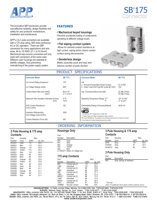
Anderson Power Products®HEADQUARTERS: 13 Pratts Junction Road, Sterling, MA 01564-2305 USA T:978-422-3600 F:978-422-3700EUROPE: Rathealy Road, Fermoy Co. Cork, Ireland T:353-(0)25-32277 F:353-(0)25-32296ASIA/PACIFIC: IDEAL Anderson Asia Pacific Ltd., Unit 922-928 Topsail Plaza, 11 On Sum Street, Shatin N.T., Hong Kong T:852-2636-0836 F:852-2635-9036CHINA: IDEAL Anderson T echnologies (Shenzhen) Ltd., Block A8 T antou W. Ind. Par, Songgang Baoan District, Shenzhen, PR. China 51810 T: 86-755-2768-2118 F: 86-755-2768-2218TAIWAN: IDEAL Anderson Asia Pacific Ltd., Taiwan Branch, 4F.-2, No.116, Dadun 20th St., Situn District, Taichung City 407, Taiwan (R.O.C.) T: 886-4-2310-6451 F:886-4-2310-6460SB ®175ConnectorPRODUCT SPECIFICATIONSThe innovative SB ® connectors provide cost-effective reliability, design flexibility and safety for your products' manufacture, installation and maintenance.APP's 2 & 3 pole connectors are availablewith a 175 amp rating, 600 Volts continuousAC or DC operation. There are SB ®connectors for many applications and wire sizes, #4 to 1/0 AWG (21.1 to 53.5mm²). Mechanical keys ensure connectors will only mate with connectors of the same color. Different color housings are selected to identify voltages, thus preventingmismatching of the power supply system.11111111116325G6 Gray #4 21.16326G6 Blue #4 21.16327G6 Orange #4 21.16328G6 Yellow #4 21.16329G6 Red #4 21.1111382 Individual 1/0 53.5947 Contact set (2) #2 33.61383 Individual #2 33.6948 Contact set (2) #4 21.11384 Individual #4 21.2948G 1* Contact set (2) #6 13.31348* Individual #6 13.3944G 1Contact set (2) #142.41347 Individual #1 42.4180BBS Bus bar contact N/A N/AFEATURES• Mechanical keyed housingsPrevents accidental mating of componentsoperating at different voltage levels • Flat wiping contact systemAllows for minimal contact resistance at high current, wiping action cleans contact surface during disconnection• Genderless designMakes assembly quick and easy and reduces number of parts stocked11* Thin wallNote: For additional colors please contact customer serviceAnderson Power Products®HEADQUARTERS: 13 Pratts Junction Road, Sterling, MA 01564-2305 USA T:978-422-3600 F:978-422-3700EUROPE: Rathealy Road, Fermoy Co. Cork, Ireland T:353-(0)25-32277 F:353-(0)25-32296ASIA/PACIFIC: IDEAL Anderson Asia Pacific Ltd., Unit 922-928 Topsail Plaza, 11 On Sum Street, Shatin N.T., Hong Kong T:852-2636-0836 F:852-2635-9036CHINA: IDEAL Anderson Technologies (Shenzhen) Ltd., Block A8 T antou W. Ind. Par, Songgang Baoan District, Shenzhen, PR. China 51810 T : 86-755-2768-2118 F: 86-755-2768-2218TAIWAN: IDEAL Anderson Asia Pacific Ltd., Taiwan Branch, 4F.-2, No.116, Dadun 20th St., Situn District, Taichung City 407, Taiwan (R.O.C.) T: 886-4-2310-6451 F:886-4-2310-6460SB ®175 ConnectorORDERING INFORMATION & DIMENSIONSTEMPERATURE RISE CHARTAccessoriesPartNumber Description 995G1 Handle, hardware & lock washers - Gray 995G3 Handle, hardware & lock washers - Red 923 Manual release, locking half with clamps and hardware 924 Manual release, mounting half with clamps and hardware110G56 Lock nut for use with Bus bar contact SB175-lockout Safety lockout 111197G1 Charger key 134G2 Dust cover945 Cable clamps 945G3 Cable clamps-2 single conductor with hardware. Use with "A" frame only.946G1 Cable clamps-1 twin conductor with hardware. Use with "A" frame only.BushingsPart WireNumber Description AWG sq. mm 5648 Use with 944 1/0 to #10 53.5 to 5.15663 Use with 944 1/0 to #6 53.5 to 13.35687 Use with 944 1/0 to #1 53.5 to 42.45690 Use with 944 1/0 to #2 53.5 to 33.65693Use with 944 1/0 to #4 53.5 to 21.2ToolingPartNumber Description 1368 Hand tool for 1/0 to #1 (53.5/42.4)1387G 1Pneumatic tool1388G3 - die for 1/0 to #1 (53.5/42.4)1388G5 - die for #41389G5 - locator for #41389G3 - locator for 1/0 to #1 (53.5/42.4)1303G4 - die for 1/0 to #4 (53.5/21.1)1304G4- locator for 1/0 to #4 (53.5/21.1)020*******800100012000.528321285122048SB175Pulse Current CapabilityDuration of Current (seconds)A m p e r e s01020304040801201602001/01 AWG 2 AWG 4 AWGSB175Temperature Rise at Constant CurrentAmperes AppliedT e m p e r a t u r e (°C)1/01 AWG 2 AWG 4 AWGContactsPart -A--B- -C- -D- Bus Bar LayoutPart - J - - K - - L- - M -Number mm in. mm in. mm in. mm in.180BBS26.8 1.05 26.8(min) 1.05(min) 9.53 0.375 3.43 0.135Mounting DimensionsHousingBus Bar Mounting TablePart - E - - F - Number mm in. mm in. 180BBS88.9 3.50 10.2 0.40Part - J -Number mm in.[53.1]2.09[25.4]1.0DS-SB175 REV05。
2-硝基苯胺-理化性质及危险特性表

隔离泄漏污染区,限制出入。切断火源。建议应急处理人员戴防尘面具(全面罩),穿防毒服。不要直接接触泄漏物。小量泄漏:用洁净的铲子收集于干燥、洁净、有盖的容器中。也可以用大量水冲洗,洗水稀释后放入废水系统。大量泄漏:收集回收或运至废物处理场所处置。
储运条件
储存注意事项:储存于阴凉、通风的库房。远离火种、热源。包装密封。应与氧化剂、还原剂、酸类、食用化学品分开存放,切忌混储。配备相应品种和数量的消防器材。储区应备有合适的材料收容泄漏物。运输注意事项:运输前应先检查包装容器是否完整、密封,运输过程中要确保容器不泄漏、不倒塌、不坠落、不损坏。严禁与酸类、酰基氯、酸酐、氯仿、强氧化剂、强还原剂、食品及食品添加剂混运。运输途中应防曝晒、雨淋,防高温。
燃烧爆炸危险性
燃烧性
可燃
燃烧分解物
一氧化碳、二氧化碳、氧化氮
闪点(℃)
无资料
爆炸上限(v%)
无资料
引燃温度(℃)
521
爆炸下限(v%)
无资料
危险特性
遇明火、高热可燃。受热分解放出有毒的氧化氮烟气。与强氧化剂接触可发生化学反应。
建规火险分级
丙类
稳定性
稳定
聚合危害
不聚合
禁忌物
酸类、酰基氯、酸酐、氯仿、强氧化剂、强还原剂。
表
标识
中文名:2-硝基苯胺;邻硝基苯胺;1-氨基-2-硝基苯
危险化学品目录序号:2229
英文名:o-nitroaniline;2-nitroaniline
UN编号:1661
分子式:C6H6N2O2
分子量:138.13
CAS号:88-74-4
理化性质
外观与性状
橙黄色针状结晶。
熔点(℃)
汉字频度表3755

1472
判
1023
乘
1073
测
921
摘
971
顿
522
师
572
望
622
断
672
架
722
运
772
救
822
弄
872
访
922
硬
972
念
523
套
573
尔
623
照
673
波
723
词
773
威
823
复
873
胡
923
育
973
羊
524
雨
574
脸
624
胜
674
今
724
戏
774
印
824
施
874
吉
924
术
974
灯
525
象
575
拍
625
根
675
录
725
丽
775
知
29
来
79
呢
129
首
179
因
229
七
279
书
329
县
379
声
429
短
479
掉
30
你
80
又
130
进
180
设
230
问
280
亿
330
办
380
交
430
专
480
色
31
就
81
图
131
即
181
应
231
52149资料

52149/52174NEGATIVE ADJUSTABLE 5-AMP 79HG REPLACEMENT VOLTAGE REGULATORMiiHYBRID MICROELECTRONICS PRODUCTS DIVISIONFeatures:• Replacementfor79HG• 5.0A Output Current•Internal Current And Thermal Overload Protection •Internal Short Circuit Current Limit•Low Drop-Out Voltage (Typically -2.2 V @ 5.0 A)•50W Power Dissipation•Electrically Isolated Case•Steel TO-3 Case Applications:•Designed for use in general purpose applications where adjustability is advantageous.•Military and Hi Rel Industrial applications where hermeticity is required.ORDER INFORMATION52149Standard52174MIL-STD-883 ScreenedDESCRIPTIONThe 52149/52174, which is a replacement for the 79HG, is an adjustable 4-terminal voltage regulator capable of supplying in excess of 5 A over a –24 V to -2.55 V output range. This Hybrid Voltage Regulator has been designed with all the inherent characteristics of the monolithic 4-terminal regulator; i.e., full thermal overload and short circuit protection. It is packaged in a hermetically sealed 4-pin, TO-3 package providing 50W power dissipation. The regulator consists of a monolithic chip driving a discrete series-pass element and short circuit detection transistors.ABSOLUTE MAXIMUM RATINGSInput Voltage.........................................................................................................................................................................-35 V Internal Power Dissipation @T c = 25°C...............................................................................................................................50W Maximum Input-to-Output Voltage Differential......................................................................................................................35 V Operating Junction Temperature.......................................................................................................................................150°C Storage Temperature Range..............................................................................................................................-55°C to +150°C Pin Temperature (Soldering, 60 seconds).........................................................................................................................300°C Commercial Temperature Range 52149..............................................................................................................0°C to +125°C Military Temperature Range 52174....................................................................................................................-55°C to +125°CMicropac Industries cannot assume any responsibility for any circuits shown or represent that they are free from patent infringement.52149/52174NEGATIVE ADJUSTABLE 5-AMP, VOLTAGE REGULATOR ELECTRICAL CHARACTERISTICST J = 25ºC, V IN = -10V and I OUT = -2.0A unless otherwise specifiedPARAMETER TEST CONDITIONS MIN TYP MAX UNITOutput Voltage Range-7.0-35VNominal Output Voltage Range V IN = V OUT -5V 2.5524VOutput Voltage Tolerance40V ≤ V IN ≤ -7V4% (V OUT)Line Regulation40V ≤ V IN ≤ -7V0.4 1.0% (V OUT)Load Regulation V IN = V OUT -10V0.7 1.0% (V OUT)-10mA ≤ I OUT ≤ -5.0AControl Pin Current 3.0µA Quiescent Current V IN = -10V7.0mARipple Rejection-18V ≤ V IN≤ -8.5V50dBV OUT = -5V, f = 120 HzOutput Noise Voltage V OUT = -5V, 10 Hz ≤ f ≤ 100kHz200µVDropout Voltage I OUT = -5A @ -0.95 V OUT-2.2VShort-Circuit Current Limit V IN= -15V812AControl Pin voltage (Reference)V IN= -10V-2.65-2.45VDESIGN CONSIDERATIONSThis device has thermal overload protection from excessive power and internal short circuit protection, which limits the circuit’s maximum current. Thus, the device is protected from overload abnormalities. Although the internal power dissipation is limited, the junction temperature must be kept below the maximum specified temperature (150ºC). It is recommended, by the manufacturer, that the maximum junction temperature be kept as low as possible for increased reliability. To calculate the maximum junction temperature or heat sink required, the following thermal resistance values should be used.PackageθJCTypical Max P D(MAX) = T J(MAX) – T AθCA = θCS + θSATO-3 1.8 2.5θ+ θCAJCSolving for T J = T A + P D (θJC + θCA)Where: T J = Junction TemperatureT A = Ambient TemperatureθCA = Case-to-ambient thermal resistanceP D = Power Dissipation θCS = Case-to-heat sink thermal resistanceθJC = Junction-to-case thermal resistanceθSA = Heat sink-to-ambient thermal resistanceThe device is designed to operate without external compensation components. However, the amount of external filtering of these voltage regulators depends upon the circuit layout. If in a specific application the regulator is more than four inches from the filter capacitor, a 2µF solid tantalum capacitor should be used at the input. A 1µF capacitor should be used at the output to reduce transients created by fast switching loads, as seen in the basic test circuit. These filter capacitors must be located as close to the regulator as possible.Caution: Permanent damage can result from forcing the output voltage higher than the input voltage. A protection diode from output to input should be used if this condition exists.VOLTAGE OUTPUTThe device has an adjustable output voltage from -2.55 to -24V which can be programmed by the external resistor network (potentiometer or two fixed resistors) using the relationship:Example: If R1 = 0Ω and R2 = 5kΩ, ThenV OUT = V CONTROL R1 + R2V OUT = -2.55 V nominal,R2or, if R1 = 12.8 kΩ and R2 = 2.1 kΩ thenV OUT = -18V.Micropac Industries cannot assume any responsibility for any circuits shown or represent that they are free from patent infringement.52149/52174NEGATIVE ADJUSTABLE 5-AMP, VOLTAGE REGULATORMechanical ConfigurationNote: All Dimension in notes and Millimeters (parenthesis)Micropac Industries cannot assume any responsibility for any circuits shown or represent that they are free from patent infringement.。
521A资料
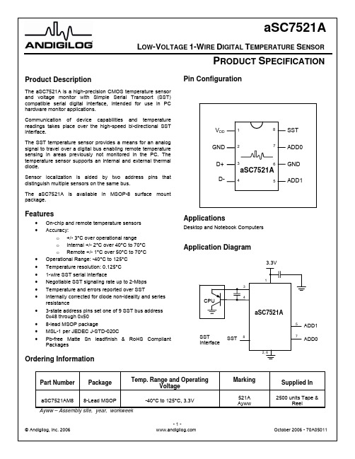
Absolute Maximum Ratings1Parameter Rating Supply Voltage, V DD-0.3, +3.63VVoltage on any Digital Input or Output3-0.3V to V DD +0.3VInput Current on any pin3±5mA Package Input Current3±20mARelative Humidity (non-operating)5% - 85% RH @ 25°C to 70°CMaximum Junction Temperature, TJmax 150°C Storage Temperature Range-60°C to +150°C IR Reflow Peak Temperature 260°C Lead Soldering Temperature (10 sec.) 300°CHuman Body Model 2000 VMachine Model 250 V ESD5Charged-Device Model >1000 V Notes:1. Absolute maximum ratings are limits beyond which operationmay cause permanent damage to the device. These arestress ratings only; functional operation at or above theselimits is not implied. For guaranteed specifications and testconditions, see the Electrical Characteristics. The guaranteedspecifications apply only for the test conditions listed. Someperformance characteristics may degrade when the device isnot operated under the listed test conditions.2. All voltages are measured with respect to GND, unlessotherwise specified.3. When the input voltage (VIN) at any pin exceeds the powersupplies (VIN< (GND or GNDA) or VIN>V+, except for SSTand analog voltage inputs), the current at that pin should belimited to 5mA. The 20mA maximum package input currentrating limits to number of pins that can safely exceed thepower supplies with an input current of 5mA to four.4. The maximum power dissipation must be de-rated at elevatedtemperatures and is dictated by TJmax, θJA and the ambienttemperature, T A. The maximum allowable power dissipation atany temperature is PD = (TJmax - TA) / θJA. It must also takeinto account self-heating that can adversely affect theaccuracy of internal sensors.5. Human Body Model: 100pF capacitor discharged through a1.5kΩ resistor into each pin. Machine Model: 200pF capacitordischarged directly into each pin. Charged-Device Model isper JESD22-C101C.Electrical Characteristics6(-40°C≤T≤+125°C, V= 3.3V unless otherwise noted. Specifications subject to change without notice)A D DParameter Conditions Min Typ Max UnitsSupply Voltage V DD 3.03.33.6VSST SignalMeets SST Specification Version 1.0for 1.5V interface-40°C≤T A≤+125°C ±3°CLocal Sensor Accuracy7, 840°C≤T A≤70°C ±2 °C Local Sensor Resolution 0.125 °C0°C≤T A≤70°C, -40°C≤T D ≤+125°C ±3 °CRemote Diode Sensor Accuracy7, 8, 90°C≤T A≤70°C,50°C≤T D ≤70°C±1 °CRemote Diode Sensor Resolution 0.125 °CTemperature Monitor Cycle Time10t C0.2SecNotes:6. These specifications are guaranteed only for the test conditions listed.7. Accuracy (expressed in °C) = Difference between the aSC7521A reported temperature and the device temperature.8. The aSC7521A can be read at any time without interrupting the temperature conversion process.9. Calibration of the remote diode sensor input is set to meet the accuracy limits with a CPU thermal diode that has a non-ideality factor of1.009 with a series resistance of 4.52Ω.10. Total monitoring cycle time for all temperature and analog input voltage measurements is 0.2 second.SST SensorsThe SST temperature sensor provides a means for an analog signal to travel over a single-wire digital bus enabling remote temperature sensing in areas previously not monitored in the PC. The temperature sensor supports an internal temperature sensor and external thermal diodes.This section outlines general requirements for Simple Serial Transport (SST) sensors intended for use in PC desktop applications that conform to SST Version 1.0 specification. The aSC7521A reports external temperature sensed by a remote diode-connected transistor and an internal temperature measurement.AddressingThe aSC7521A complies with the address range set aside for fixed-address, discoverable devices as defined in the SST Specification Version 1.0. Simple Temperature sensors use fixed addresses in the range of 0x48 to 0x50. The aSC7521A may be programmed to any of these addresses via the address select pins AD0 and AD1.Frame Check Sequence (FCS)Each message requires a frame check sequence byte to ensure reliable data exchange between host and client. The message originator and client both make an FCS calculation. One FCS byte must be returned from the message target to the originator after all bytes including the header and the data block are written. If data is read from the target, a second FCS byte must follow the data block read.The FCS byte is the result of an 8-bit cyclic redundancy check (CRC) of the each data block preceding the FCS up to the most recent, earlier FCS byte. The first FCS in the message does not include the two address timing negotiation ‘0’ bits that precede the address byte or the message timing negotiation bit after the address byte. The first FCS does include the address byte in its computation. The FCS is initialized at 0x00 and is calculated in a way that conforms to a CRC-8 represented by the CRC polynomial, C(x) = x8 + x2 + x + 1.Bus VoltageAll SST sensor devices used for PC applications must be capable of operating the SST interface portion of the sensor device at 1.5 volts as defined in 1.5 Volt Static (DC) Characteristics section of the SST Version 1.0 specification. Bus TimingAll SST sensor devices must be able to negotiate timing and operate at a maximum bus transfer rate of 2-Mbps. If the bus address timing is negotiated at a lower rate due to the performance limitations of other devices on the bus, the sensor device will operate at that lower rate. Device Power-on TimingFollowing a power-on reset, such as a system transitioning from S3-S5 to S0, the aSC7521A will be able to participate in the address and message timing negotiation and respond to required SST bus commands such as respond to a GetDIB() command within 10ms of the device’s V DD rail reaching 90%. The aSC7521A has an internal power on reset and will be fully functional within 50ms of power on.The aSC7521A does not employ any device power management.Voltage and Temperature Sensor DataLittle Endian FormatThe bit level transfer is defined in the SST specification. The 2-byte data values are returned in little Endian format, in other words, the LSB is sent first followed by MSB.For multi-function devices that allow access to multiple sensors, the data is returned LSB followed by the MSB for the first sensor, LSB followed by the MSB for the second sensor, and so on. The specific order is explicitly specified in the command description.Atomic ReadingsThe aSC7521A ensures that every value returned is derived from a single analog to digital conversion and is not skewed (e.g. the MSB and the LSB come from two different conversions).Conversion TimeThe maximum refresh time for all temperature values is200ms. The aSC7521A provides the logic to ensure all readings meet the conversion time requirements. Temperature DataData Precision, Accuracy and ResolutionThe temperature data meets the following minimum requirements:•Operational Range: -40°C to +125°C•Internal Sensor Accuracy:o+/- 3°C over operational rangeo+/- 2°C over 40°C to 70°C•Remote Sensor Accuracy (when TA is from 0°C to 70°C):o+/- 3°C over operational rangeo+/- 1°C over 50°C to 70°C• Resolution:0.125°CTemperature Data FormatThe data format is capable of reporting temperature values in the range of +/-512°C. The temperature sensor data is returned as a 2’s complement 16-bit binary value. It represents the number of 1/64°C increments in the actual reading. This allows temperatures to be represented with approximately a 0.016°C resolution.Values that would represent temperatures below -273.15°C (0 K or absolute zero) are reserved and are not be returned except as specifically noted.For the aSC7521A the required resolution is 0.125°C. Bits [2:0] will be defined but they are beyond the required resolution. The sign bit will indicate a negative temperature except when reporting an error condition (see Sensor Error Condition). Temperature 2’s complement representation 80°C 0001 0100 0000 0000 79.875°C 0001 0011 1111 1000 1°C 0000 0000 0100 0000 0°C 0000 0000 0000 0000-1°C 1111 1111 1100 0000-5°C 1111 1110 1100 0000 Table 1. Temperature RepresentationSign Integer Temperature 0°C to 512°CFractionalTemperatureLSB 0.125°CAlways Zero15 14 13 12 11 10 9 8 7 6 ● 5 4 3 2 1 0Figure 2. Temperature ReadingA to D Converter Resolution and MappingThe mapping of the A-D converter bit values is a two’s complement representation with the binary point between bits 5 and 6 of the 16-bit data word. Bit 15 is the sign, bits 14 through 6 are integer temperature in degrees, bits 5 down to 3 are the fractional part with 0.125°C as the LSB. The lowest 3 bits are set to zero.Temperature InputsThe simple temperature sensor has an internal thermal sensor plus an external sensor using a remote diode. Both temperature readings are internally corrected for lead resistance and non-ideality for the thermal diode of a Pentium™ 4, 65nM process (1.009 non-ideality, 4.35Ω lead resistance). The range of measurement currents falls within the Intel recommended range of 10μA and 170μA to minimize the impact of Beta variation in the CPU substrate thermal diode. Note that Pentium 4, 90 nM process is 1.011 non-ideality and series resistance of 3.33Ω.If a diode connected discrete transistor is used instead of a CPU diode, a correction must be applied to the reading to compensate for the difference in non-ideality. A 2N3904 NPN transistor has a non-ideality (η) factor of approximately 1.04. To correct the value reported to the actual temperature use the following formula:T ACTUAL = T REPORTED x ηTransistor / 1.009 It is recommended that the actual transistor type and manufacturers chosen for the remote sensor be characterized for non-ideality as part of system qualification. Sensor Error ConditionThe aSC7521A has the capability to detect and report open or shorted external diode inputs per Sensor Error Condition. When an error or failure condition is detected, the sensor device must return a large negative value in response to either the GetIntTemp() or GetExtTemp() command. In this manner software is provided with a means to determine whether or not the sensor is working normally and that the data returned is good.The aSC7521A will write one of the values from the table below to appropriate memory locations for GetIntTemp() and/or GetExtTemp().The aSC7521A uses the OEM defined values of 0x8102 (open) and 0x8103 (short) rather than the generic errors defined for codes 0x8000 to 0x8003.Error Code Description0x8000 to 0x80FF Reserved0x8102 Remote Diode Open0x8103 Remote Diode Short0x8100-0x81FF ReservedTable 2. Error CodesSST InterfaceMulti Client ModeSensors operate in multi-client mode for read bit timing. Reference the SST Specification Version 1.0 for details.SST Device CommandsGetDIB() Command (0xF7)Read the Device Identifier Block (DIB). The read length of the command is either 8 or 16 bytes. 8 bytes is the minimum number of bytes populated by a fixed address discoverable client.Write Data Length: 0x01Read Data Length: 0x08/0x10Command Code: 0xF7Note: Un-shaded table entries are created by the host. Shaded entries are the response bytes from the aSC7521A to the host.# Bits # BitsHost Sending aSC7521A SendingHex Value Hex Value8 8 8 8 8Target Address Write Length Read Length GetDIB Cmd FCS0x48 0x01 0x10 0xF7 0xDC8 8 8 8 8DIB Byte 1 … DIB Byte 15 DIB Byte 16 FCS(data) (data) (data) (data) (data dependent)Figure 3. GetDIB() Command (16-byte read length)8 8 8 8 8Target Address Write Length Read Length GetDIB Cmd FCS0x48 0x01 0x08 0xF7 0x238 8 8 8 8DIB Byte 1 … DIB Byte 7 DIB Byte 8 FCS (data) (data) (data) (data) (data dependent)Figure 4. GetDIB() Command (8-byte read length)Ping() CommandThe Ping() command provides a safe means for software to verify that a device is responding at a particular address.Write Data Length: 0x00Read Data Length: 0x00Command Code: none8 8 8 8Target Address Write Length Read Length FCS0x48 0x00 0x00 0xD7Figure 5. Example of Ping()ResetDevice() CommandThe ResetDevice() command is used to reset all device functions to their power-on reset values. It is used by the system to recover from serious hardware or bus errors.Write Data Length: 0x01Read Data Length: 0x00Command Code: 0xF68 8 8 8 8Target Address Write Length Read Length ResetDeviceCommandFCS0x48 0x01 0x00 0xF6 0x8C Figure 6. ResetDevice() format targeting a non-default address8 8 8 8Target Address Write Length Read Length ResetDevice Command0x00 0x01 0x00 0xF6Figure 7. ResetDevice() format targeting the default addressSensor Command SummaryGetIntTemp()Returns the temperature of the device’s internal thermal sensor.Write Data Length: 0x01Read Data Length: 0x02Command Code: 0x00Example bus transaction for a thermal sensor device located at address 0x48 returning a value of 60°C:8 8 8 8Target Address Write Length Read Length Command0x48 0x01 0x02 0x008 8 8 8FCS LSB MSB FCS0x6A0x000x0F0x2DFigure 8. Get Internal Temperature Command ExampleGetExtTemp()Returns the temperature of the external thermal diode.Write Data Length: 0x01Read Data Length: 0x02Command Code: 0x01GetAllTemps()Returns a 4-byte block of data containing both the Internal and External temperatures in the following order Internal then External temperatures.Write Data Length: 0x01Read Data Length: 0x04Command Code: 0x00Optional SST Device CommandsThe optional SST commands Alert(), Suspend() are not supported in the aSC7521A.Vendor Specific ExtensionsThe vendor specific command codes are in the range from 0xE0 and 0xE7. Reading and writing to specific internal registers is provided for custom tuning of sensor response characteristics.WriteReg()Writes to the sensor’s internal registers.Write Data Length: 2+N (command + address + Number of bytes to write)Read Data Length: 0x00Command Code: 0xE0Example bus transaction to write to a sensor located at address 0x48. This example writes 2 consecutive locations (0x20 and 0x21) to values 0x25 and 0x28.8 8 8 8Target Address Write Length Read Length Command0x48 0x04 0x00 0xE08 8 8 8RAM Addr Write Data Write Data FCS0x20 0x25 0x28 0x1BFigure 9. Example Register WriteReadReg()Reads from the sensor’s internal registers.Write Data Length: 0x02 (command + address)Read Data Length: N (Number of bytes to read)Command Code: 0xE1Example bus transaction to read a sensor located at address 0x48. This example reads 2 consecutive locations (0x20 and 0x21).8 8 8 8Target Address Write Length Read Length Command0x48 0x02 0x02 0xE18 8 8 8RAM Addr FCS Read Data Read Data FCS0x20 0x9D 0x25 0x28 0x37Figure 10. Example Register ReadVenCmdEnable()Vendor Command Enable enables the Vendor Specified Extensions.Write Data Length: 0x01Read Data Length: 0x00Command Code: 0xE28 8 8 8 8Target Address Write Length Read Length Command FCS0x48 0x01 0x00 0xE2 0xE0Figure 11. Vendor Command EnableVenCmdDisable()Vendor Command Disable disables the Vendor Specified Extensions.Write Data Length: 0x01Read Data Length: 0x00Command Code: 0xE38 8 8 8 8Target Address Write Length Read Length Command FCS0x48 0x01 0x00 0xE3 0xE7Figure 12. Vendor Command DisableReserved or Unsupported CommandsAttempts to access the sensor using a reserved or unsupported command will not result in the device or bus failure. The sensor will return a modified FCS when any of the following commands are received. To modify the FCS the sensor will invert all of the bits in the correct FCS (1’s complement). A modified FCS is also called an Abort FCS.The sensor will return an Abort FCS (modified FCS) for a reserved and unsupported command code (commands codes between0xE4 to 0xF5 and 0xF8 to 0xFF).The sensor will return an Abort FCS (modified FCS) for reserved commands (command codes 0x02 to 0xDF.The sensor will return an Abort FCS (modified FCS) for unused vendor specific test and manufacturing command codes (command codes 0xE8 to 0xEF). If any of these types of commands exist, they will be disabled during normal operation.Malformed CommandsA malformed command is one which is valid but has an incorrect write or read length for the given command.If a get temperature command with a write length not equal to 1 is sent, then the aSC7521A will send an Abort FCS and wait for a new command. An Abort FCS will be formed by creating a 1’s complement of the the good FCS.If a get temperature command and the read length is not equal to 2 or 4 then te aSC7521A will send an Abort FCS and wait for a stop on the SST bus. See the Command Summary section for the expected Write and Read lengths of the legal commands.There will be no checking for malformed WriteReg() and ReadReg() commands (Vendor Specific Extensions).Command SummaryHex CmdCommand NameReceived BytesWr LenRd LenBytes Sent by Client- Ping()3(target,wr,rd) 0 0 FCS 0x00 GetIntTemp()4(target,wr,rd,cmd) 1 2 FCS/2/FCS 0x01 GetExtTemp()4(target,wr,rd,cmd) 1 2 FCS/2/FCS 0x00 GetAllTemps()4(target,wr,rd,cmd) 1 4 FCS/4/FCS 0x02-0xDF Unsupported Abort FCS 0xE0 WriteReg()4(target,wr,rd,cmd) 3+ 0 FCS 0xE1 ReadReg()4(target,wr,rd,cmd) 2 1+ FCS/1+/FCS 0xE2 VenCmdEnable()4(target,wr,rd,cmd) 1 0 FCS 0xE3 VenCmdDisable()4(target,wr,rd,cmd) 1 0 FCS 0xE4-0xF5 Unsupported Abort FCS 0xF6 ResetDevice()4(target,wr,rd,cmd) 1 0 FCS 0xF6 ResetDevice()4(target,wr,rd,cmd) 1 0 None if default address (0x00) 0xF7 GetDIB()4(target,wr,rd,cmd) 1 8 FCS/8/FCS 0xF7 GetDIB()4(target,wr,rd,cmd) 1 16 FCS/16/FCS 0xF8-0xFF Unsupported Abort FCSTable 3. Command SummaryDevice Identifier Block (DIB)The Device Identifier Block describes the identity and functions of a client device on the SST bus. Sixteen bytes are allocated for this function as shown in Figure 13. Device Identifier Block is returned by the aSC7521A with a GetDIB() command. The aSC7521A returned values are shown with the description of each field below.8 8 16 16 8Vendor ID Device ID Device Capabilities Version/Revision LSB MSB LSB MSBDevice Interface8 8 8 16 24 8FunctionInterfaceDeviceInterface ExtensionReserved ReservedVendor Specific ID Client Device Address Figure 13. Device Identifier BlockDevice Capabilities Field (1-byte)MSB 6 5 4 3 2 1 LSBAddress Type ReservedWake Capable Alert Support Suspend SupportSlowDevice 110 0 0 0 0 0Figure 14. Device Capabilities FieldVersion / Revision Field (1-byte)MSB 65 4321LSBPre-release SST Version Minor Revision1 0010000 (default) for V1.0 Pre-production 00010000 for V1.0 ProductionFigure 15. Version / Revision FieldVendor ID Field (2-bytes)Andigilog Vendor ID is 16 bits = 0x19C9 (This field is stored in the format LS Byte, MS Byte = 0xC919). Vendor IDs can be foundat: /membership/vid_searchDevice ID Field (2-bytes)This field uniquely identifies the device from a specific vendor. Place the least significant byte as the first byte and the most significant byte as the second byte.Part Number Value (MS,LS) Stored Value (LS,MS) aSC7521A 0x7521 0x2175Device Interface Field (1-byte)The vendor sets to ‘1’, bit positions in this field in the event the device supports higher layer protocols that are industry specific using Table 4.Value = 0x02Bit Protocol Meaning 7 - Reserved for future use , must be set = ‘0’ 6 - Reserved for future use , must be set = ‘0’ 5 IPMI Device supports additional access and capabilities per the IPMI specification. 4 ASF Device supports additional access and capabilities per the ASF specification. 3 Serial-ATA Device supports additional access and capabilities per the serial-ATA specification.2 PCI-ExpressDevice supports additional access and capabilities per the PCI Expressspecification.1 SSTDevice supports additional access and capabilities per the SST FunctionalDescriptor Specification (to be published at a future date).0 OEMDevice supports vendor-specific additional access and capabilities per the VendorID and Device ID.Table 4. Device Interface FieldFunction Interface Field (1-byte)This field provides a mechanism for a device to pass higher-layer SST device-specific information.Value = 0x00Device Interface Extension Field (1-byte)This field is used to provide additional information about the device to the upper layers of software.Value = 0x00Reserved Field (3-bytes)Value = 0x00 0x00 0x00Vendor Specific ID Field (1-byte)This field is set by the vendor in a way that uniquely identifies this device apart from all others with an otherwise common DIB content.Value = 0x00 – For Fixed address devices this field may be set to zero.Client Device Address (1-byte)SST Client Device Address is set according to the connection of pins ADD0 and ADD1. Float is defined as an unconnected pin.ADD0 ADD1 AddressGround Ground 0x48Float Ground 0x49V DD Ground 0x4AGround Float 0x4BFloat Float 0x4CV DD Float 0x4DGround V DD0x4EFloat V DD0x4FV DD V DD0x50sensor is very close to the circuit board temperature and typically between the board and ambient.In order to measure PC board temperature in an area of interest, such as the area around the CPU where voltage regulator components generate significant heat, a remote diode-connected transistor should be used. A surface-mount SOT-23 or SOT-223 is recommended. The small size is advantageous in minimizing response time because of its low thermal mass, but at the same time it has low surface area and a high thermal resistance to ambient air. A compromise must be achieved between minimizing thermal mass and increasing the surface area to lower the junction-to-ambient thermal resistance.In order to sense temperature of air-flows near board-mounted heat sources, such as memory modules, the sensor should be mounted above the PC board. A TO-92 packaged transistor is recommended.The power consumption of the aSC7521A is relatively low and should have little self-heating effect on the local sensor reading. At the highest measurement rate the dissipation is less than 2mW, resulting in only a few tenths of a degree rise.Notes:Andigilog, Inc.8380 S. Kyrene Rd., Suite 101 Tempe, Arizona 85284Tel: (480) 940-6200Data Sheet ClassificationsPreliminary SpecificationThis classification is shown on the heading of each page of a specification for products that are either underdevelopment (design and qualification), or in the formative planning stages. Andigilog reserves the right to change ordiscontinue these products without notice.New Release SpecificationThis classification is shown on the heading of the first page only of a specification for products that are either underthe later stages of development (characterization and qualification), or in the early weeks of release to production.Andigilog reserves the right to change the specification and information for these products without notice.Fully Released SpecificationFully released datasheets do not contain any classification in the first page header. These documents containspecification on products that are in full production. Andigilog will not change any guaranteed limits without writtennotice to the customers. Obsolete datasheets that were written prior to January 1, 2001 without any headerclassification information should be considered as obsolete and non-active specifications, or in the best case asPreliminary Specifications.Pentium™ is a trademark of Intel CorporationLIFE SUPPORT POLICYANDIGILOG'S PRODUCTS ARE NOT AUTHORIZED FOR USE AS CRITICAL COMPONENTS IN LIFE SUPPORT DEVICES ORSYSTEMS WITHOUT THE EXPRESS WRITTEN APPROVAL OF THE PRESIDENT AND GENERAL COUNSEL OF ANDIGILOG,INC. As used herein:1. Life support devices or systems are devices or systems which, (a) are intended for surgical implant into the body, or (b)support or sustain life, and whose failure to perform when properly used in accordance with instructions for use provided in thelabeling, can be reasonably expected to result in a significant injury to the user.2. A critical component is any component of a life support device or system whose failure to perform can be reasonably expectedto cause the failure of the life support device or system, or to affect its safety or effectiveness.Andigilog, Inc.8380 S. Kyrene Rd., Suite 101Tempe, Arizona 85284Tel: (480) 940-6200。
术语92 95 98

术语92 95 98一、引言在计算机科学和信息技术领域,有许多术语被广泛使用,其中包括”92”、“95”和”98”。
这些术语通常与特定的技术、标准或版本号相关联。
本文将详细介绍这些术语的含义和应用。
二、922.1 含义在计算机领域,“92”通常指的是“802.11b”的标准,也称为Wi-Fi标准。
该标准是用于无线局域网(WLAN)中的一种通信协议,支持最高传输速率为11 Mbps (兆比特每秒)。
该标准于1999年发布,并在当时成为了无线网络通信的主流。
2.2 应用802.11b标准广泛应用于家庭和办公室网络中,以提供无线互联网接入。
通过无线路由器或接入点,用户可以通过Wi-Fi连接到网络并享受高速上网体验。
此外,许多移动设备、笔记本电脑和智能家居设备都支持802.11b标准。
三、953.1 含义在信息技术领域,“95”通常指的是“Windows 95”操作系统。
Windows 95是由微软公司开发的一款操作系统,于1995年发布。
它是微软首个采用图形用户界面(GUI)的操作系统,对个人电脑的用户界面和功能进行了重大改进。
3.2 特点Windows 95引入了许多重要的功能和概念,如开始菜单、任务栏、桌面图标等。
它还支持32位应用程序,并提供了更好的多任务处理能力。
此外,Windows 95还改进了文件管理器、网络支持和设备驱动程序等方面。
3.3 影响Windows 95对个人电脑行业产生了巨大影响。
它的发布标志着GUI操作系统在市场上的普及,并为后续版本如Windows XP、Windows 7等奠定了基础。
此外,Windows 95还推动了计算机硬件和软件产业的发展,为互联网时代的到来做出了贡献。
四、984.1 含义在计算机科学领域,“98”通常指的是“HTTP/1.1”协议。
HTTP(Hypertext Transfer Protocol)是一种用于在Web浏览器和Web服务器之间传输数据的协议。
28824;中文规格书,Datasheet资料

Web Site: Forums: Sales: sales@Technical: support@Office: (916) 624-8333Fax: (916) 624-8003Sales: (888) 512-1024Tech Support: (888) 997-8267 ServoPAL (#28824): Servo Pulser and TimerGeneral DescriptionThe ServoPAL is a tiny module that plugs in between your BASIC Stamp and two servo motors to pulse the motors so your PBASIC program doesn’t have to. In addition, it provides an “alarm clock” function to perform timing in the background while the BASIC Stamp is busy with other tasks.Features• Plugs in between servo headers and servos: no wiring necessary.• Simplifies PBASIC programming for both standard and continuous-rotation servos.• Pulses two servos continuously based on single pulses received from the BASIC Stamp.• Provides an alarm output (200mS to 30 min delay), which can be set by a single pulse.• All interfacing is done by pulsing: no serial protocols to learn.• Runs from the servo’s power (up to 6.5VDC): no additional power source needed.• Compact size: stackable side-to-side with additional units on 0.1” servo headers.What’s IncludedServoPAL moduleWhat You Need to Provide• BASIC Stamp and carrier board (such as the BOE).• One or two servo motors.InstallationInstallation of the ServoPAL is a simple:1. Unplug the servo connectors from the servo headers.2. Plug the ServoPAL into the servo headers. (See diagram below.)3. Plug the servo connectors into the ServoPAL.Gnd Gnd VddVdd /InpAlarm Gnd GndVdd Vdd Servo 0Servo 1Top View Servo Header Everything ConnectedBelow is a photo of the ServoPAL installed on a BOE-Bot’s P12/P13 servo header. The wheel servo motor cables are plugged into the ServoPAL. In this case, the /Inp input pin is P12, the Alarm output pin is P13, the right servo is Servo 0, and the left servo is Servo 1.Hardware Interface and InitializationInterface to the ServoPAL is realized through its /Inp input and Alarm “output”. When the ServoPAL powers up, both lines are configured as normally-high inputs, pulled up to a nominal +5V through internal 20K to 50K resistances. Commands to the ServoPAL are sent as negative pulses to the /Inp pin. If the alarm feature is not used, the BASIC Stamp can use the Alarm pin for any other purpose. If this is done, however, you must be careful not to trigger an alarm inadvertently, or else a bus conflict may occur.The ServoPAL runs autonomously on power obtained from the servo headers. Therefore, it does not reset when the BASIC Stamp resets, and continues to send out pulses during and after reset if it was sending them out before. But it can be reset, nonetheless, by sending a pulse of 100mS duration to the /Inp pin. Here’s the recommended initialization sequence for the ServoPAL in PBASIC:'{$STAMP BS2}'{$PBASIC 2.5}nInp PIN12'Define the input pin.Alarm PIN13'Define the alarm pin.Restart:INPUT nInp'Make sure nInp isn't being driven.DO UNTIL nInp'Wait for ServoPAL to power up.LOOPLOW nInp'Set pin to an output and hold it lowPAUSE100'for100mS.HIGH nInp'Raise the pin.This sequence accomplishes a couple things:1. In systems, like the BOE-Bot, where the servo power is switched on after the BASIC Stamppowers up, it will wait for the ServoPAL to be turned on. It does this by setting the nInp line to an input and waiting for that line to go high, signifying not only that that the ServoPAL has powered up, but that it has come out of reset and engaged its internal pull-ups.2. In case the ServoPAL was already running, it then sends a long reset pulse to terminate anyservo pulses, to abort any pending alarm, and to ready the ServoPAL for further commands. Programming Servo PulsesServo pulses are programmed in much the same way you’d send pulses directly to a servo motor, using the PBASIC PULSOUT command. The only differences are that the pulses are negative-going instead of positive and that both servos are programmed from the same pin. Here’s an example that will cause the Servo 0 output to begin pulsing with 1.5mS pulses. These pulses are automatically repeated every 10-15mS without further intervention from the BASIC Stamp.PULSOUT nInp,750Notice that this is identical to the statement that would have been used, had the servo been connected directly to the BASIC Stamp. Once the initialization code is executed, your program is primed for negative-going pulses, and you don’t need to do anything special to send them. Here’s what the waveforms look like that result from the above example:/InpServo 0But what about Servo 1? There’s only one pin, so how does it get programmed? That’s easy: just send another pulse within 1mS of the first one, and that one will be assigned to Servo 1:PULSOUT nInp,750PULSOUT nInp,1000The preceding code will program Servo 0 with a pulse width of 1.5mS and Servo 1 with a pulse width of 2.0mS. Here’s what the waveforms will look like:/InpServo 0Servo 1To terminate a sequence of pulses on /Inp, just wait at least 2mS before sending another pulse. This signals the ServoPAL that the next pulse is intended for Servo 0.Now, what if you want to program only Servo 1 and leave Servo 0 alone? That’s easy, as well. Just send a very short pulse (4 – 100µS) for Servo 0 first, then a pulse for Servo 1. The ServoPAL will interpret the short pulse as indicating that you don’t want to change Servo 0’s pulse stream, if one has already been programmed. Here’s an example:PULSOUT nInp,2PULSOUT nInp,500Here’s what the resulting waveforms look like:/InpServo 0Servo 1And finally, what if you want to terminate a servo’s pulse stream? The ServoPAL will only send pulses to a servo that are between approximately 0.5 and 2.5mS. If it encounters a request for pulses well outside this range, it will cease sending pulses to the affected servo. Here’s how you can use this to stop sending pulses to a servo:PULSOUT nInp,2000'Send a4mS pulse to Servo0.Here’s the result:/InpServo 0Servo 1To summarize, here’s a table showing the various pulse durations and what they mean:4 - 100µS Skip this servo. (Don’t change its output.)0.5 - 2.5mS Program this pulse width into the affected servo.4 – 30mS Kill the servo’s output.100mS or more Reset the ServoPAL.Pulse widths outside the individual ranges shown may have unpredictable effects.Programming the Alarm FunctionIn addition to servo control, the ServoPAL has an alarm clock (timer) function. You can set an alarm tooccur anywhere from 200mS to 30 minutes after it’s set (triggered). For programming purposes, the timer is treated by the ServoPAL as a third servo: i.e. after sending pulses for Servo 0 and Servo 1, yousend a pulse for the timer. As soon as such a pulse is received, the Alarm output is pulled low. It will remain low until the programmed time elapses, whereupon it will again float and be pulled high by meansof the internal pullup resistor.The relation between the pulse width sent by the BASIC Stamp and the actual time programmed into thetimer isProgrammed time = Pulse width * 50000 (approximately)So a pulse width of 4µS yields a timeout of 200mS, and a pulse width of 36000µS yields a timeout of 30minutes. In terms of PULSOUT units, here’s the timing for various BASIC Stamps:BS1 BS2 BS2e BS2sx BS2p BS2pe BS2px Time perPULSOUT unit 500mS 100mS 100mS 40mS 40mS 100mS 40mS MaximumPULSOUT units 3600 18000 18000 45000 45000 18000 45000 Here’s a BS2 program fragment that sets the timeout period to 5 minutes:PULSOUT nInp,4'Skip Servo0.PULSOUT nInp,4'Skip Servo 1.PULSOUT nInp,3000'Set timeout to300seconds.And here’s the output waveform:/InpAlarm 6mS300000mS = 5 min.One additional thing to note about the timer is that it’s retriggerable. What this means is that if you set itbefore a previous setting has timed out, it will start over with the new timeout value. This feature makes the ServoPAL useful as a watchdog timer for the BS2p, BS2pe, and BS2px, which support automaticpolling. As long as you keep resetting the watchdog timer, the Alarm output will stay low. But if your program hangs up somewhere, the timer will eventually time out and the rising edge on Alarm can be used to (re)start the program specified by POLLRUN.Simple Example ProgramHere’s a simple-minded BS2 program that moves a BOE-Bot forward for 5 seconds, then in reverse for five seconds, using the Alarm output as a timer:'=========================================================================''File......ServoPAL_Simple_Demo.bs2'Purpose...Demonstrate ServoPAL capabilites on a BOE-Bot'Author....Parallax,Inc.'E-mail....support@'Started...2007.05.01'Updated...2007.10.29''{$STAMP BS2}'{$PBASIC 2.5}''========================================================================='-----[Program Description]---------------------------------------------'This simple demo of the ServoPAL,when used with a BOE-Bot,will move the'robot forward for five seconds,then in reverse for five seconds.'-----[I/O Definitions]-------------------------------------------------nInp PIN12'Define the input pin.Alarm PIN13'Define the alarm pin.'-----[Initialization]--------------------------------------------------INPUT nInp'Make sure nInp isn't being driven.DO:LOOP UNTIL nInp'Wait for ServoPAL to power up.LOW nInp'Set pin to an output and hold it lowPAUSE100'for100mS to reset ServoPAL.HIGH nInp'Raise the pin.PAUSE100'-----[Program Code]----------------------------------------------------PULSOUT nInp,500'Program right servo for full forward.PULSOUT nInp,1000'Program left servo for full forward.PULSOUT nInp,50'Program alarm for5seconds.DO:LOOP UNTIL Alarm'Wait for Alarm.PULSOUT nInp,1000'Program right servo for full reverse.PULSOUT nInp,500'Program left servo fro full reverse.PULSOUT nInp,50'Program alarm for5seconds.DO:LOOP UNTIL Alarm'Wait for Alarm.PULSOUT nInp,2000'Turn right servo off.PULSOUT nInp,2000'Turn left servo off.DO:LOOPIR Roaming ProgramThe next example is an IR roaming program for the BOE-Bot. To use this program, you should connect the IR emitters and sensors as shown in Parallax’s Robotics with the Boe-Bot, figure 7-4 (copied below).The program works like this:1. Start the BOE-Bot moving forward.2. Keep checking for obstacles until one is found.3. If obstacle is on left or right, begin turning in opposite direction.4. If obstacle is in front, back up for one second, then begin turning right for at least ½ second.5. Continue evasive action until clear of obstacles AND any timed motion has completed.6. Go to step 1.Here’s the program:'=========================================================================''File......ServoPAL_IR_Roaming.bs2'Purpose...BOE-Bot IR Roaming Program using ServoPAL'Author....Parallax,Inc.'E-mail....support@'Started...2007.10.29'Updated...''{$STAMP BS2}'{$PBASIC 2.5}''========================================================================='-----[Program Description]---------------------------------------------'This program uses the ServoPAL in conjuction with IR emitters and'detectors to steer the BOE-Bot past obstacles in encounters in its'path.'-----[I/O Definitions]-------------------------------------------------IRDetR PIN0'Righthand IR detector.IREmtR PIN2'Righthand IR emitter.IREmtL PIN8'Lefthand IR Emitter.IRDetL PIN9'Lefthand IR detector.nInp PIN12'ServoPAL input pin.Alarm PIN13'ServoPAL alarm pin.'-----[Constants]-------------------------------------------------------NONE CON0RIGHT CON1LEFT CON2BOTH CON3BKWD CON0FWD CON3'-----[Variables]-------------------------------------------------------Obstacle VAR Nib'Reading from IR detectors.Move VAR Nib'Motor command.Time VAR Word'-----[Initialization]--------------------------------------------------INPUT nInp'Make sure nInp isn't being driven.DO:LOOP UNTIL nInp'Wait for ServoPAL to power up.LOW nInp'Set pin to an output and hold it low PAUSE100'for100mS to reset ServoPAL.HIGH nInp'Raise the pin.PAUSE100'-----[Program Code]----------------------------------------------------DOMove=FWD'Start BOE-Bot moving forward,GOSUB DoMotor'using the DoMotor routine.DOGOSUB ReadIR'Read obstacle detectors, LOOP UNTIL Obstacle'until an obstacle is found.IF(Obstacle=LEFT)THEN'Obstacle on the left?Move=RIGHT'Yes:Start rotating right.GOSUB DoMotorELSEIF(Obstacle=RIGHT)THEN'On the right?Move=LEFT'Yes:Start rotating left.GOSUB DoMotorELSEIF(Obstacle=BOTH)THEN'In front?Move=BKWD'Yes:Start backing up,Time=10'and set alarm for1sec.GOSUB DoMotorDO UNTIL Alarm:LOOP'Wait for alarm to time out.Move=RIGHT'Then start rotating right,Time=5'setting alarm for1/2sec.GOSUB DoMotorENDIFDO'Evasive action is being taken.GOSUB ReadIR'Read the obstacle detectors.LOOP UNTIL Obstacle=NONE AND Alarm'Continue(timed)evasive maneuver,'until clear AND time is up. LOOP'-----[Subroutines]-----------------------------------------------------'------[ReadIR]----------------------------------------------------------'Read both IR sensors.Put inverted values into position in Obstacle.ReadIR:FREQOUT IREmtR,1,38500'Activate the right IR emitter.Obstacle.BIT0=~IRDetR'Read the right IR sensor(and invert).FREQOUT IREmtL,1,38500'Activate the left IR emitter.Obstacle.BIT1=~IRdetL'Read the left IR sensor(and invert).RETURN'------[DoMotor]---------------------------------------------------------'Start motors turning to move BOE-Bot in direction indicated.If Time>0,'then set alarm and clear Time to zero.DoMotor:IF(Move=BKWD)THENPULSOUT nInp,900PULSOUT nInp,600ELSEIF(Move=LEFT)THENPULSOUT nInp,600PULSOUT nInp,600ELSEIF(Move=RIGHT)THENPULSOUT nInp,900PULSOUT nInp,900ELSEPULSOUT nInp,600PULSOUT nInp,900ENDIFIF(Time)THENPULSOUT nInp,TimeTime=0ENDIFRETURN分销商库存信息: PARALLAX 28824。
- 1、下载文档前请自行甄别文档内容的完整性,平台不提供额外的编辑、内容补充、找答案等附加服务。
- 2、"仅部分预览"的文档,不可在线预览部分如存在完整性等问题,可反馈申请退款(可完整预览的文档不适用该条件!)。
- 3、如文档侵犯您的权益,请联系客服反馈,我们会尽快为您处理(人工客服工作时间:9:00-18:30)。
Dialight Corporation • 1501 Route 34 South • Farmingdale, NJ 07727 • TEL: (732) 919-3119 • FAX: (732) 751-5778 •
6-35
元器件交易网
.64 [.025]
5.08 [.200] 4.57 [.180] 1.0 [.040] MAX 25.1 [1.00] MIN 1.27 [.050]
1.0 [.040] MAX
CATHODE
Dimensions in mm [inches]
MOUNTING CLIP: 515-0004 located on page 6-48
5.2 [.205]
2.54 [.100] 6.35 [.250]
550-0507-004 550-0707-004 550-0807-004
LOW CURRENT
RECOMMENDED P.C. HOLE PATTERN
Dimension A: 3.4 [.135] for -0207 to -0407, 4.95 [.195] for all others Dimension B: .635 [.025] for -0507 to -0707, .508 [.020] for all others Hole Diameter: 1.22 [.048] for .635 [.025] leads, 1.02 [.040] for all others
Test Current (mA) 20 20 20
Viewing Angle 2 Θ½ 60° 60° 60°
LED Data sheet 5ND-9674 5ND-9673 5ND-9672
Page # 6-51 6-51 6-51
INTEGRAL RESISTOR Part Number 550-0507-004 550-0707-004 550-0807-004 LOW CURRENT Part Number 550-1107-004 550-1207-004 550-1307-004 Color Red Yellow Green Peak Wavelength nm 635 583 565 IV mcd 2 1.8 1.8 VF Volts 1.8 1.9 1.8 Test Current (mA) 2 2 2 Viewing Angle 2 Θ½ 50° 50° 50° LED Data sheet 521-9320 521-9321 521-9327 Page # 6-42 6-42 6-42 Color Red Green Yellow Peak Wavelength nm 655 565 583 IV mcd 2 8 8 Test Voltage 5 5 5 Forward Current (mA) 13 12 10 Viewing Angle 2 Θ½ 60° 60° 60° LED Data sheet 5RD-9422 5RD-9423 521-9284 Page # 6-52 6-52 6-41
Tolerance note: As noted, otherwise:
• LED Protrusion: ±0.04 mm [±0.016] • CBI Housing: ±0.02mm[±0.008]
Series
Reverse Polarity (Cathode Left) option available. See Part Number Ordering Code.
HIGH EFFICIENCY Part Number 550-2207-004 550-2307-004 550-2407-004 550-2507-004 BI-COLOR Part Number Color Peak Wavelength nm 660/565 585/565 IV mcd 90/40 8.7/8.7 VF Volts 1.8/2.1 2.1/2.1 Test Current (mA) 20 20 Viewing Angle 2 Θ½ 60° 50° LED Data sheet 521-9651 521-9724 Page # 6-46 6-46 Color Green Yellow Red Orange Peak Wavelength nm 563 585 650 600 IV mcd 10 6.3 7 7 VF Volts 2.1 2.1 2.2 1.9 Test Current (mA) 10 10 10 10 Viewing Angle 2 Θ½ 65° 50° 50° 60° LED Data sheet 5HD-9270-5 5HD-9271-5 5HD-9269 521-9704 Page # 6-49 6-49 6-49 6-43
5.97 [.235] 3.0 [.118]
4.69 [.185]
550-0207-004 550-0307-004 550-0407-004
B
INTEGRAL RESISTOR
2.54 [.100]
CATHODE Red Cathode for Red/Green Bi-Color Yellow Cathode for Yellow/Green Bi-Color
元器件交易网
5mm LED CBI® Circuit Board Indicator Sloped Back Housing, Quad Block
PART NO.
25 [.984] 2.97 [.117] 6.35 [.250] CATHODE ID A 9.01 [.355]
IV mcd 34 34 34
VF Volts 2.1 2.2 2.2
Test Current (mA) 20 20 20
Viewing Angle 2 Θ½ 50° 50° 50°
LED Data sheet 5SD-9441 5SD-9456 5SD-9455
Page # 6-53 6-53 6-53
元器件交易网
550-xx07-004
Typical Operating Characteristics (TA=25°C)
GENERAL PURPOSE Part Number 550-0207-004 550-0307-004 550-0407-004 Color Green Yellow Red Peak Wavelength nm 565 585 635 IV mcd 12.3 12.3 12.3
Red Yellow
ABSOLUTE MAXIMUM RATINGS (TA=25°C) Forward Voltage (V) Derating (V/°C) From 50°C Operating Temperature (°C) Storage Temperature (°C) Soldering Temperature
550-1107-004 550-1207-004 550-1307-004
HIGH EFFICIENCY
Dimensions in mm [inches]
Standard Polarity shown in drawing: Cathode right
Features
• Multiple CBIs form horizontal LED arrays on 6.35mm (0.250”) center-lines. • • • • • • High Contrast, UL 94 V-0 rated, black housing Oxygen index: 32% Polymer content: PBT, 0.680 g Housing stand-offs facilitate PCB cleaning Solderability per MIL-STD-202F, method 208F LEDs are safe for direct viewing per IEC 825-1, EN-60825-1 • Compatible with: 550-xx07 Single-Block 550-xx07-002 Dual-Block
550-3007-004 Red/Green 550-3107-004 Yellow/Green SUPER BRIGHT, DIFFUSED Part Number 550-5107-004 550-5207-004 550-5307-004 Color Red Green Yellow
6
Peak Wavelength nm 650 563 585
See LED data sheet for additional information See page 6-55 and 6-56 for Reference Only LED Drive Circuit Examples. See page 6-58 for Pin Out
VF Volts 2.1 2.1 2
SUPER BRIGHT, WATER CLEAR (NON-TINTED, NON-DIFFUSED) Part Number 550-5507-004 550-5607-004 550-5707-004 Color Red Green Yellow Peak Wavelength nm 635 565 583 IV mcd 125 120 140 VF Volts 2.2 2.3 2.2 Test Current (mA) 20 20 20 Viewing Angle 2 Θ½ 24° 24° 24° LED Data sheet 521-9464 521-9465 521-9466 Page # 6-47 6-47 6-47
5mm Discrete LED Integral Resistor, 5 Volts Diffused
521-9183, -9284
5.84 [.230]