Unified design of iterative receivers using factor graphs
全波形反演
全波形反演,一纬,二维Frequency-domain full-waveform tomography for visco-acoustic media.! #! # Program FWT2D is a massively parallel code for distributed memory platform ! # which performs frequency-domain full-waveform inversion of seismic data [10,11,12,13].! # The program is more specifically designed for wide-angle or global offset data !!!!!!!!!更特别设计! # (that is, for any acquisition system involving dense wide-aperture acquisitions ! # and for which sources share a significant range of receivers spanning over large ! # offsets). The inversion looks for the P-wave velocity only. However, heterogeneous! # density and attenuation can be provided for the forward modeling.! # The inversion relies on a classic iterative steepest descent algorithm [1,2]. Iterations !!!!!!反演依赖于经典的迭代最速下降法! # are performed in a non linear way which means that the final model at a given ! # iteration is used as the starting model for the next iteration.! # Single or group of frequencies are inverted successively. The classic procedure ! # is to proceed from the low frequencies to the higher ones [3]. Note however that! # all the frequencies can be inverted simultaneously by defining a single group ! # of nw frequencies (nw is the total number of frequencies to be inverted).! # The cost function is based on the least-squares norm. The cost function is weighted !!!!!!!!!!!!!!!成本函数是基于最小二乘范! # with an operator which applies a gain with offset to the residuals.! # The gradient of the cost function is properly scaled by the diagonal terms of the ! # approximate hessian J^t J where J is the sensitivity matrix [4].! # The source can be approximated in the program solving a linear inverse problem! # (see [2], [10], [13]).! # The step length is computed by parabolic fitting.抛物线拟合! # The forward problem, that is, wave propagation modeling, is performed with a ! # finite-difference frequency-domain method [6,7,14] and relies on a direct solver to! # solve the associate sparse system of linear equations whose right-hand sides(RHS) are! # the sources. We use the massively parallel direct solver MUMPS for distributed memory! # platform to solve this system [15,16].! # Note however that the code can also be run in sequential (see MUMPS documentation).! # Absorbing boundary condition in the FDFD code are combination of PML [9,14] and 4。
基于遗传算法的递归MTI自适应滤波器的设计
信息疼术2018卑第7期文章编号:1009 -2552(2018)07 -0090 -04 DOI:10. 13274/j. cn k i. h d z j. 2018. 07. 021基于遗传算法的递归M T I自适应滤波器的设计殷万君\金炜东2(1.四川信息职业技术学院,四川广元628040; 2.西南交通大学,成都610031)摘要:针对自适应滤波器在F P G A上实现结构灵活性的特点,文中提出了一种基于遗传算法的 递归M T I自适应滤波器的设计方法。
根据遗传算法的特点,结合滤波器的性能指标,阐述了设 计思想,通过遗传算法实现了自适应滤波器的权系数寻优,在系数寻优中采用了创新的适应度 函数和惩罚函数,通过场景仿真,验证了文中所提算法的实用性和有效性。
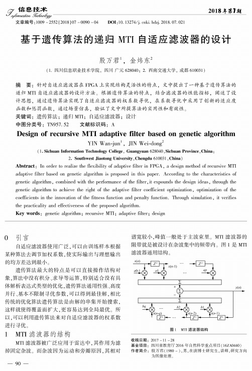
关键词:遗传算法;递归M T I;自适应滤波器;设计中图分类号:T N957.52 文献标识码:ADesign of recursive MTI adaptive filter based on genetic algorithmYIN Wan-jun1,JIN Wei-dong2(1. Sichuan Inform ation Technology College,Guangyuan 628040,Sichuan Province,China;2. Southwest Jiaotong University,Chengdu 610031,China)Abstract :In order to realize the fle x ib ility o f adaptive filte r in F P G A,a design m ethod o f recursive M T I adaptive filte r based on genetic a lgo rithm is proposed in th is p a p e r.A c co rd in g to the cha racteristics o f genetic a lg o rith m,com bined w ith the perform ance o f the f ilt e r,it expounds the design id e a s,through the genetic a lgo rithm to achieve the rig h t of the adaptive filte r co e fficie n t o p tim iz a tio n,op tim iza tio n of the coe fficien ts in the in no vation o f the fitness fu n c tio n and pe na lty fu n c tio n.Through s im u la tio n,it verifies the p ra c tic a lity and effectiveness o f the proposed a lg o rith m.Key words:genetic a lg o rith m;recursive M T I;adaptive f ilt e r;design0引言自适应滤波器使用广泛,可以由训练样本根据某种算法去调节加权系数,使实际输出与理想输出的均方差达到最小。
飞泛(Futaba)Futaba14SG R7 firmware更新说明书
February 2020—Firmware and FAA RID NPRMAs February greets us many have chosen to set theirhobby interests aside, or at least limit their participa-tion to inside for the past couple months. The winterbuild is a time-honored tradition in the northern cli-mates. In addition to getting new aircraft ready forwhen the weather warms and the winds calm it’s theperfect time to give our existing airframes a thoroughexamination for signs of wear, or potential failure. It’salso a good time to check to see if our transmitters, re-ceivers, or ESC’s may have pending firmware updates.The advantage of firmware updates is they often givenew capabilities for your existing hardware, or fix pre-viously unknown defects. However, sometimes as newfeatures are introduced or patched another featuremay be inadvertently broken by the update. The avail-ability of an update does not mean it’s necessary foryour use. As an example, when Futaba released up-date 7 for the Futaba14SG they inadvertently intro-duced a range check failure on startup. Futaba recent-ly introduced update 9 to fix the range check failure onstartup issue. Firmware updates tend to be an iterativeprocess with customers being the final test of function-Futaba Software DownloadFrSky Important Update for ACCST D16 FrSky Firmware Downloads Spektrum Firmware Updates Jeti Firmware Updates Graupner Updates Castlelink UpdatePersonal safety is not the only topic to discuss this month. The survival of our hobby is very much threatened by the recent FAA RID Notice of Pro-posed Rulemaking (NPRM). The FAA published their plan requiring broadcast from all aircraft weighing over 250 grams (0.55 pounds) on Dec 31. ality. FrSky recently released a new firmware for ALL of their D16 ACCST transmitters and receivers back to 2013 (OpenTX as well as FrOS). The firm-ware addresses a serious issue –if you’re in the Eu-ropean Union. The FCC (American) version of transmitters/receivers are not significantly affect-ed, especially if operated where the airwaves are not crowded with many 2.4ghz signals. One take-away from this is noting that when applying radio firmware updates be sure to note that you have downloaded FCC version and not EU. I recom-mend waiting on the FrSky ACCST updates for a couple months as this is a major update and there will inevitably be bugs. I’d rather do the updates one time since this transmitter update also requires that all receivers are updated.In summary; when checking over all the clevises, horns, pushrods, screws, motor mounts etc, don’t forget to check where you stand regarding what you can’t see –the firmware. Additionally, be judi-cious about applying a recently introduced firm-ware especially if it’s a major update. Finally, be sure you’re using the FCC radio firmware and not the EU version.Don’t be misled by the term “drone” in the NPRM. The FAA uses the term “drone” to apply to all Un-manned Aircraft Systems(UAS), this includes every-thing we fly at TCRCM field and may even include free flight and control line. This NPRM is open for public comment until March 2. The AMA, and EAA (Experimental Aircraft Association) as well as others petitioned in vain for an extension to the comment period. In response to the request for an extention FAA replied on January 28:“…the need for remote identification of UAS increas-ingly has become important as new public safety and national security concerns arise regarding the use of UAS. Accordingly, the FAA has determined that any extension of the comment period, and the subse-quent delays in promulgation of a final rule imple-menting remote identification of UAS, would not be consistent with the safety and security objectives of the proposed rule.Therefore, your request to extend the comment pe-riod for the Remote Identification of Unmaimed Air-craft Systems NPRM is denied. The comment period for the NPRM closes on Monday, March 2, 2020.”Once one dives into the 319 page NPRM in depth it details how the FAA is proposing to progressively annihilate the hobby. This NPRM proposes to make it illegal for a land owner to fly over their own land in the short term, and eventually eliminate model flying fields for home-built aircraft like we now fly. There are many many levels of concern. Grouping Line of Sight (LOS) modeling in with the regulations of Beyond Visual Line of sight BVLOS operations is a one size fits all solution that is inappropriate. Making it impossible to establish new flying fields, or even move an existing club flying field to a new location is well beyond what Congress mandated in the FAA reauthorization act of 2018. To assist with digesting the information about the NRPM, Jim Andersan has posted a page of infor-mation on the Club Website. There are also links to two summaries of the NPRM in the sources below.It’s seriously imperative that all interested reach out to the FAA and to all elected representatives. Even if your position is that you have no intention of follow-ing these rules then politely tell the FAA that they can expect noncompliance from otherwise law abid-ing citizens.Some would say that contacting FAA or representa-tive will make no difference. If that’s the case we’re no worse off and you did what you could. Your com-ments MAY make a difference in which case it’s time and energy well spent.Links to Contacts:• Dan Newhouse• Patty Murray• Maria Cantwell• White House• FAA RID NPRM Comment pageLinks to Information and resources.• Layman’s Guide to the NPRM for Remote ID• AMA summary of the RID NPRM• AMA Templates to use to assist in drafting your own response.• Our club website。
allegro_pcbsigxl_ds学习资料(可编辑)

allegro_pcbsigxl_ds学习资料IC package andSiP designPCB designI/O bufferdesign IC designPackagedesign-in kitSilicondesign-in kitOn-target, on-timesystem interconnectInterconnectmodelsI/O bufferIPVirtual systeminterconnectmodelVerifyBuildCorrelateSpecifyExploreDesignImplementDATASHEETALLEGRO PCB SI GXLCadence? Allegro? PCB SI GXL provides a virtual prototyping environment fordesigns with signals operating in the multi-gigahertz MGH frequency range. Itoffers a completely integrated signal design and analysis solution built on top ofthe proven Allegro PCB SI environment. Its advanced technology shortens designcycle time and eliminates the need for multiple lab qualifications with fullfunctional physical prototypes.THE ALLEGRO SYSTEMINTERCONNECT DESIGNPLATFORMThe Cadence Allegro systeminterconnect design platform enablescollaborative design of high-performance interconnect across IC,package, and PCB domains. Theplatform’s unique co-designmethodology optimizes systeminterconnect?between I/O buffersand across ICs, packages, and PCBs?toeliminate hardware re-spins, decreasecosts, and reduce design cycles. Theconstraint-driven Allegro flow offersadvanced capabilities for designcapture, signal integrity, and physical implementation. With associatedsilicon design-in IP Portfolios, ICcompanies shorten new deviceadoption time and systems companiesaccelerate PCB design cycles for rapidtime to profit. Supported by theCadence Encounter? and Virtuoso?platforms, the Allegro co-designmethodology ensures effective designchain collaboration.The Allegro system interconnect design platform ALLEGRO PCB SI GXLDesigning system interconnects withsignals operating in the MGH rangerequires capabilities that quickly and accurately model each element of thesignal’s path. This is because at high frequencies the losses on a signalmount as the signal travels through different discontinuities such as vias, connectors, and different layers in one or more printed circuit boards. At gigahertz GHz frequencies, the lossin a transmission line can amount to approximately 0.25+ dB/inch, creating challenges for longer interconnects on PCB systems. Ensuring that losses in critical signals are acceptable is an important step in the design of MGH signals. To accomplish this, Allegro PCB SI GXL lets engineers perform loss budget tradeoffs quickly anditeratively using S-Parameters. It also provides a way to change the MGHsignal’s topology and view expectedloss through the system interconnect within seconds.Allegro PCB SI GXL offers engineers a highly integrated virtual prototyping environment that includes built-in productivity capabilities for MGH designs. It addresses MGH design challenges in an integratedenvironment that is easy to use and includes several advanced modules: SigXplorer topology exploration environment; high-capacity simulation, SPICE-based simulation subsystem; Allegro Constraint Manager; Allegro Model Integrity; floorplanner/editor and PCB Router; and EMControl. Technological advances?such as differential signals with embedded clocks serial links, drivers with pre- emphasis, and receivers with equalization?allow engineers to architect systems that have higher performance and throughput.However, many of the EDA solutions required to design systems such as these have not kept pace, leaving engineers forced to use disparate, stand-alone products to design systems with high-speed signals, particularly those that operate in MGH range. Allegro PCB SI GXL addresses the numerous challenges typically created as system designers work to provideultra-high bandwidth for data transferagainst shrinking market windows.Another key challenge for MGHdesigners involves ensuring thattiming and voltage margins indifferential signals used in serial linksare met. As traditional circuit simulatorsare limited to approximately 1024 bitsof custom stimulus pattern length,the effect of inter-symbol interferenceISI is not adequately modeled. Toaccurately predict the eye opening,engineers need solutions that cansimulate stimulus patterns of over onemillion bits. On a typical PC/Windowsplatform, Allegro PCB SI GXL cansimulate 10,000 bits in just secondsone million bits in an hour.BENEFITSEliminates the need for physicalprototypes for multiple qualificationsthrough advanced simulationtechniquesShortens design cycle time throughfaster tradeoffs of MGH signals usingS-Parameters and single or coupledanalytical via modelingImproves product quality, cost, andperformanceSaves time via a virtual prototypingenvironment that is seamlesslyintegrated with other Allegroplatform design productsFEATURESINTEGRATED S-PARAMETER SUPPORTIntegrated S-Parameter support enablesengineers to generate S-Parametersfrom PCB signal t opologies “Stack-upto S” and plot in SigWave quickly andeasily. Users can change topology orstack-up and do quick iterative lossbudget tradeoffs. It also allowsdesigners to concatenate multipleS-Parameters into one, simulateS-Parameters in time domain, andincorporate S-Parameters for an objectinto the topology and then generateS-Parameters for the entire topologyAdditionally, by incorporating S-Parameter support that is flexible,Allegro PCB SI GXL allows engineers toincorporate measurement-basedS-Parameter models in native Touchstoneformat. S-Parameters with otherinterconnect topologies can also beincorporated, measured, or importedAny portion of the passive interconnect can be plotted as S-Parameter in SigWavetopology explorer2MACRO MODELINGMacro modeling capabilities enableengineers to model and simulateMGH drivers and receivers faster andmore accurately?with simulationperformance improvements of 20x to400x over transistor-level simulation.VIA MODEL GENERATORUsers can quickly create accuratevia models wideband, narrowband,S-Parameter to simulate via stubeffects at MGH frequencies for singlevias, differential vias, and vias coupledwith ground/power vias.HIGH-CAPACITY, HIGH-PERFORMANCESIMULATIONThe Channel Analysis module withinAllegro PCB SI GXL addresses the needfor high-capacity simulation that canensure timing and voltage margins aremet for MGH signals. The Channel Analysis module allows users tosimulate up to 10 million bits very rapidly. On a typical PC/Windows platform, it can simulate 10,000 bits in just seconds, a million bits in an hour. Users can quickly develop meaningful configurations “tap settings” for a complex driver or receiver. To determine optimal settings, designers get a recommendation for a specific topology in seconds, saving weeks of simulation time.SIGXPLORER TOPOLOGYEXPLORATION ENVIRONMENTSigXplorer is used for pre-route topology design and analysis, even before a schematic is created. Thistype of analysis is common at the earliest stages of the design cycle when designers assess the impact of using a new device technology or of increasing bus transfer rate. SigXplorer can be used to build and validate detailed electrical topology modelsand prove the viability of a new technology?before the detaileddesign process begins.Integrated solution space explorationis provided through the SigXplorer topology editor and simulationcockpit. Engineers can model frequency- dependent losses and skin effect accurately for MGH signals with an integrated field solver. Quick trial implementation is possible using the tightly integrated Allegro PCB Router XL. SPICE-BASED SIMULATIONSUBSYSTEMThe Allegro PCB SI GXL circuitsimulation engine TlSim is a proven SPICE-based simulator that combinesthe advantages of traditional SPICE- based structural modeling with thespeed of behavioral analysis. TlSim includes the capability to simulateS-Parameters in time domain. By combining both structural andbehavioral modeling techniques, Tlsim enables engineers to accurately andefficiently model complex devicebehavior. Tlsim also includes a lossycoupled, frequency-dependenttransmission line model that accuratelypredicts the distributed behavior ofPCB traces into the GHz rangeALLEGRO CONSTRAINT MANAGERAllegro Constraint Manager allowsusers to capture, manage, and validatevarious rules in a hierarchical fashion.It provides a real-time display of high-speed rules and their status based onthe current state of a design. WithHigh-pass filterDSP techniques RxDe-emphasisMulti-tapTxUsers need proven advanced macro modeling capabilities for devices with preemphasis ofreceiver equalization without sacrificing simulation performance Eye shrinks with number of bits in stimulus pattern. A good eye diagram is important foraccurate jitter, insertion loss, and BER prediction34Allegro Constraint Manager designerscan group all of the high-speedconstraints for a collection of signalsand form an electrical constraint setECset that is then associated withthose nets to manage their actualimplementation. ECSets can be usedto drive the PCB layout design process,shortening the design cycle time.ALLEGRO MODEL INTEGRITYThe Model Integrity module allowsdesigners to quickly create, manipulate,and validate models in an easy-to-useediting environment. Device modelformats supported include:IBIS 4.1 External Model support for Verilog?-A, Spectre?, HSPICE, CadenceeSpice modelsMentor/Quad XTKCadence Device Modeling Language DMLA Spectre-to-DML conversion moduleassists in creating DML models fromSpectre simulation runs. With theoutput of the Spectre simulation runbuffer options file, users can quicklycreate DML models. Model integrityidentifies V-I and V-T tables for typical,imum, and minimum corner casesfrom the Spectre run file. A proven,intelligent best-curve-fitting algorithmprovides an accurate DML model. AnHSPICE-to-IBIS conversion moduleallows users to create IBIS modelsfrom HSPICE simulation runs.Complete library managementthrough Model Integrity lets usersread and write touchstone formatS-Parameters, check passivity ofS-Parameters, and plot S-Parameters?all with the click of a button. FLOORPLANNER/EDITOR AND PCBROUTERThe floorplanner provides a graphicalview of the PCB database allowingusers to view, simulate, and edit thePCB design. Designers can quickly andeasily evaluate the effects of different placement strategies on designbehavior. They can also perform testrouting using proposed electrical constraints to ensure high-speed design rules are achievable before passingthem on to the PCB layout designerEMCONTROL By applying a combination ofstandard rules and user-defined rules, EMControl can eliminate weeks ofmanual checking and improve product quality and reliability. For a standard rule set, EMControl provides comprehensive, knowledge-based,design rule checking DRC forcommon EMI-related placement androuting issues. For user-defined rules, EMControl allows creation of custom rules that fit within a company’sdesign guidelines. Importantly, these rules capture the high-speed design “experience” as customized rules, which in turn can be reused on future designs. The EMControl module predicts far-field differential-mode radiated emissions in both SigXplorer and the Allegro PCB SI floorplanner. It also allows for exploration of design strategies required to keep radiation within acceptable levels. Near-field EMI analysis, available within the Allegro PCB SI floorplanner, canpredict radiated energy immediately above the board surface. By analyzing near-field EMI patterns, designers canidentify which portions of a routedtrace are producing the most radiatedenergy and adapt the design accordingly.I/O BUFFER MODELSSupported I/O buffer model formatsinclude:Cadence Allegro PCB SI DeviceModeling Language DMLSynopsys HSPICE transistor-levelmodels requires HSPICE simulator andlicense, which is not included withAllegro PCB SI GXLCadence Spectre transistor-levelmodels available on Sun Solaris, HPUX, and Linux RHEL 3.0 platformsonly. This utilizes an integrated andlimited capability version of theSpectre simulator, which is includedwith Allegro PCB SI GXLIBIS 4.1 External Model support for HSPICE, Spectre, Verilog-A, andCadence DMLMentor/Quad XTKINTEGRATION AND INTERFACESAllegro PCB SI GXL reads and writesAllegro PCB database .brd files andprovides interface to Mentor BoardStation layout database.OPERATING SYSTEMSUPPORTRed Hat Linux 3.0, 4.0Windows 2000 with Service Pack 4,XP ProfessionalSun Solaris 8, 9, 10HP-UX 11.11iIBM AIX 5.3CADENCE SERVICES ANDSUPPORTCadence application engineers cananswer your technical questions bytelephone, email, or Internet?theycan also provide technical assistanceand custom trainingCadence certified instructors teachover 70 courses and bring their real-world experience into the classroomOver 25 Internet Learning Series iLSonline courses allow you the flexibilityof training at your own computer viathe Internet SourceLink? online customer supportgives you answers to your technicalquestions?24 hours a day, 7 days aweek?including the latest in quarterlysoftware rollups, product changerelease information, technicaldocumentation, solutions, softwareupdates, and moreVia model generator allows users to modelstub effects at MGH frequencies duringpre-route exploration and analysis phaseof the design processFOR MORE INFORMATIONContact Cadence sales at 1.800.746.6223or visit //0>. foradditional information. To locate aCadence sales office or CadenceChannel Partner in your area, visit//./contact_us 2006 Cadence Design Systems, Inc. All rights reserved. Cadence, the Cadence logo, Allegro, Encounter, SourceLink, Spectre, Verilog, and Virtuoso are registered trademarks Cadence Design Systems, Inc. All others are properties of their respective holders.5585E 07/06ALLEGRO PCB SI FEATURESMajor feature summary for SI, Allegro Design Entry HDL, Allegro PCB SI GXL, and Allegro PCB PI Option XLAllegro PCB Allegro Design Entry Allegro PCB Allegro PCB PISI XL HDL SI XL SI GXL Option XLAllegro Design Entry HDL XL xAssign Models in Schematics xCreate Xnets in Schematics xApply Constraints and Topologies to Schematic for Single-ended and Differential Nets xSingle-line Topology Editor Graphical Canvas x x xSimulation Setup Advisor x xModel Integrity: Model Development Environment x x xModel Integrity: Syntax Checking for IBIS 3.2 and DML x x xModel Integrity: HSPICE-to-IBIS Conversion x x xIBIS 4.0 Models Support x x xQuad Models Translator x x xSpectre Transistor-level Models x x x xMacro-models Support DML x x xSimulation Control: Single-line Simulation x x xWaveform Viewer x x xDetailed Simulation Reports Such as Flight Time, Overshoot, Noise Margin x x xCoupled 3 Net Simulation x xCoupled 3nets Simulation x xSingle Net Pre-layout Extraction from Allegro Design Entry HDL x x xAllegro Physical Viewer PlusDifferential Pair Exploration and Simulation x x xDifferential Pair Pre- and Postlayout Extraction from Allegro PCB Editor x xDifferential Pair Pre-layout Extraction from Allegro Design Entry HDL x x xDifferential Signal Constraint Capture x x xCoupled Line Simulations x x xCrosstalk Simulation x x xSweep Simulations x x xCurrent Probes x x xMultiterminal Black Boxes in Topologies x x xConstraint Development and Capture of Topologies x x xCustom Measurement x x xCustom Stimulus x x xBatch Simulation x xEMControl: Rules Development x xEMControl: Rules Checking x xEMI Differential Simulation x x xAllegro Constraint Manager x x xColor-coded Real-time Feedback on Violations xApply Constraints and Topologies to Board for Single-ended and Differential Nets x xFloorplanner x xConstraint-driven Floorplanning and Routing x xAllegro PCB Router XL x xHSPICE Simulator Interface x x x xS-Parameter Generation from Stackup xS-Parameter Plotting in SigWave xTime Domain Simulation of S-Parameters xLibrary Management of S-Parameters in Model Integrity xCoupled Via Model Generator for Pre-layout Explorations xHigh Capacity Simulation Using Channel Analysis Overlay xOptimum Pre-emphasis Bit Configurations “Tap Settings” xPower Integrity: Design and Analysis Environment xPower Integrity: Decoupling Capacitor Database Setup Wizard xPower Integrity: Impedance Requirements Calculator xPower Integrity: Decoupling Capacitor Selection and PlacementEnvironment xPower Integrity: VRM Editor xPower Integrity: Decoupling Capacitor Library Editor xPower Integrity: Cross-probing Between Waveform Allegro PCB SI Floorplanner xPower Integrity: Frequency Domain Analysis x。
2.设计原则PRINCIPLES OF DESIGN

Lesson 10 PRINCIPLES OF DESIGNThe principles of design are the rules or guidelines governing the use of the elements. They tell us how to use color,texture,line,shape and space to create an organized system or composition. These principles are based on what we know of human nature and how we,as human beings,perceive and evaluate our aesthetic surroundings.We have already discussed the theory that all the elements are present in design,that they are interrelated and interdependent upon one another.Now we must learn how to use them to create a concept,a plan,a scheme that functions as a unified arrangment. We must understand the role of the design principles and the various ways they can be manipulated to provide a response to various human needs and desires. Just as words and punctuation marks require a set of principles on sentence structure in order to convey a thought,elements of design require a set of principles to convey a design concept.A landscape,for instance,can be an array of trees,shrubs,plants,stones,cement,and flowers in a given area,but a landscape design is planned and constructed according to a set of principles that govern the arrangement of those elements.All design is an arrangement of its parts based on these same basic principles. The three basic principles of design are: proportion,balance and rhythm.PROPORTIONProportion means the relationship of size between objects and the space the object occupies.We perceive all objects as having a certain proportion or size as they relate to the size of other objects. A apple can be described as big if we see it in comparison with smaler apples. If we were to describe this apple we are seeing for the first time we could not de scribe it as being bigger or smaller than usual because we wouldn't know what is "usual".Imagine that some one handed you an object that is approximately two inches square. Y ou would have no way of knowing whether "it" was a big one or a small one because you have nothing with which to compare its size. If you were told that it was a thimble,you would think it was a very large one because other thimbles we have seen are finger size. If you were told it was a radio then you would think it was small since other radios are usualymuch larger than two inches.SIZE AND SPACE RELATIONSHIPSAnother way we view proportion is by comparing an object to the space it occupies. A apple is big if it doesn't fit into the lunchbox even though it might be smaller than some other apples. A baby might be con sidered big when he has outgrown his cradle even though he might be small compared with other babies of the same age. A leaf could be small compared with a tree,and a book could be large in comparison with the size of the bookshelf.So when we are describing objects as a proportion by relative sizes,we can describe them in two ways:1 By comparison with other similar objects.2. By comparison with the space they occupy.COMPAING MASS AND VOIDAnother way of describing proportion is by comparing mass to void.Mass is the property of an object that gives it substance; mass is the visual or structured weightof an object or element .V oid is the lack of weight or substance. Mass is positive while void is negative.UNITY AND CONTRASTIn any arrangement or composition,we are seeing all of the elements present in their various degrees of dominance / subordinance. Since they all interrelate with each other,we are at once comparing not only various qualities of the same elements,but also various qualities of different elements. Those qualities that are similar in dominance / subordinance provide unity within a composition. Those qualties that are very dissimilar provide contrast.In our study of proportion,we have learned:1 Proportion is a size and space relationship.2. Proportion is a ratio of mass (object )to mass.3. Proportion is a ratio of mass (object) to void (space) .4. Dominant elements are considered positive (massive),while subordinate elements are considered negative (less massive).5. Similar qualities provide unity; while dissimilar qualties provide contrastBALANCEBalance means the equilibrium of the elements of design.As humans, we innately understand the principles of design. They bring order to our lives. Our instinct for proportion tells us when something is "out of whack". Likewise,an arrangement that is not balanced seems lopsided and sometimes upseting. Balance is identified as an equilibrium of the elements.When dominance is equally distributed within a design,you have achieved balance. We feel a design is unbalanced when weights or dominance are not equally distributed. Imagine an orderly bookcase with a series of volumes supported by matching bookends. If one bookend is removed,an actual imbalance will occur. The books will fall over. Visually the same conclusion can be drawn by observing a room with all the furniture moved to one end. While physically the room does not tip,the illusion of instability ,or tipping,occurs.The principle of balance can fall into three categories: symmetrical balance,asymmetrical balance and radial balance.SYMMETRICAL BALANCESymmetry is a correspondence in size,shape and relative position on opposite sides of an imaginary dividing line,median plane or a center of an axis. We must remember,however,that we are dealing with all the elements when organizing a balanced design. Dominating colors,textures and lines provide visual weight and must be distributed equally. A room with the furniture equally distributed in a symmetrical arrangement will appear lopsided if an intense red, coarse textures and heavy lines are all grouped on one side of the imaginary dividing line. This is an example of a visual imbalance.ASYMMETRICAL BALANCEAsymmetrical balance has parts that are different in size,shape and number,and / or relative position on opposite sides of a deviding line. They are still balanced in that they still have similar weight or substance,but the elements are not the same.RADIAL BALANCERadial balance is an a rrangement with a central axis whose parts are located equally or correspondingly around a central point - similar to rays. Some examples of radial balance observed around us are: the sun,and aerial view of a pine tree,or a dining centerpiece,and chandelier.In our study of balance we have learned:1. Balance is necessary to create a unified arrangement2. The three types of balance are: symmetrical,assymmetrial,and radial.3. Imbalance can be used to create contrastRHYTHMRhythm is the movement or natural eye flow caused by the regular reoccurence of related elements. Those elements in design that are related - that is,similar in color,texture,line,shape,or space - create eye movement. A grouping of related elements causes the eye to naturally flow from one element to an other in an organized manner. This eye movement or rhythm gives unity to the composition. A break or change in the rhythm provides contrastCONTINUOUS RHTHMContinuous rhythm,as the word implies,is a constant element,uninterrupted by change,either in color,texture,line,shape,or space. A unbroken line is continuous.REPETITIVE RHYTHMA repetitive rhythm is a group of like objects or elements in an arrangement set at equal intervals or at random intervals. Although they may be set at unequal intervals,our eye still tends to follow them,creating unity because the elements are the same or have a high degree of similarity. The eye follows the flow naturally from one element to another visually unifying our line of vision.PROGRSSIVE RHYTHMProgressive rhythm is presentation in a composition utilizing similar or like elements that gradually change. The change may be one of size,height,color intensity or value,texture,or shape. A series of textures from flat to shiny or coarse to fine is also a progressive rhythm. So is a series of shapes that get gradually bigger or taller or shorter or smaller.In our study of rhythm we have learnedRhythm causes eye movement and visual unity.There are three types of rhythm: continuous repetitive, and progressive.A break in the rhythm of elements provides contrast.设计原则是管理设计元素应用的规则和方针。
基于DFT码本的预编码

题目:基于DFT码本的预编码学院:通信工程学院专业:电子与通信工程******学号:**********基于DFT码本的预编码摘要本文主要研究了在预编码技术中,针对反馈开销十分昂贵,为了节约成本采用基于DFT码本选择的预编码,并对预编码过程进行了性能仿真。
仿真结果表明,在4×2天线模式下基于DFT码本的预编码简单实用,并且随着不同反馈比特数的增加,基于DFT 码本的预编码技术的系统性能随之增加。
关键词预编码 DFT 码本选择1.引言随着现代移动通信中对吞吐量和频谱效率要求的不断提高,对于基于多天线的多输入多输出的MIMO技术的研究不断深入。
而在多用户MIMO系统中,存在的主要问题就是各个用户之间存在干扰。
预编码技术的提出则有效的抑制了MIMO信道中的多用户干扰,不仅如此预编码技术在MIMO系统中能显著提升信道容量,并大大降低接收机的复杂度,成为当前的研究的关键技术之一。
预编码技术就是在已知信道状态信息(CSI)的情况下,在发射端调整发射策略,接收端进行均衡,从而提高MIMO系统的性能。
在多用户MIMO下行链路中,各个用户之间无法相互协作,不能利用上行链路的联合检测来恢复发射信号,因此预编码是多用户MIMO下行链路获得复用增益和分集增益的关键。
预编码技术可以分为基于码本的预编码方式和基于非码本的预编码方式。
基于码本的预编码方法要求发送端和接收端共享一套码本集合,然后根据具体的信状况从一个确定的矩阵集合中选取一个使系统性能最优的矩阵,再将矩阵在码本集合中的序号反馈给发送端。
这样的编码方案是针对反馈信道十分昂贵的开销提出的,并且反馈信道所需传输的数据量很小,只需要几个比特的大小,大大节约了成本。
而基于非码本的预编码是在发送端已知信道信息状态的情况下,对信道信息矩阵H进行适当的分解,进而得到相应的发射端预编码矩阵、接收端均衡矩阵和将MIMO信道变换成若干个独立子信道的等效信道矩阵.2.基本原理2.1预编码基本原理预编码技术是在发射端已知或可以获得信道状态信息的情况下,利用信道状态信息对待发射信号进行预处理的技术,从而进一步提高系统的吞吐量。
测试英语单词

Configuration testing : 配置测试
conformance criterion: 一致性标准
Conformance Testing: 一致性测试
consistency : 一致性
consistency checker: 一致性检查器
Acceptance testing : 验收测试
Acceptance Testing:可接受性测试
Accessibility test : 软体适用性测试
actual outcome:实际结果
Ad hoc testing : 随机测试
Algorithm analysis : 算法分析
diagnostic:诊断
DIF(decimation in frequency) : 按频率抽取
dirty testing:肮脏测试
disaster recovery:灾难恢复
DIT (decimation in time): 按时间抽取
documentation testing :文档测试
Buddy test : 合伙测试
Buffer : 缓冲
Bug : 错误
Bug bash : 错误大扫除
bug fix : 错误修正
Bug report : 错误报告
Bug tracking system: 错误跟踪系统
bug:缺陷
Build : 工作版本(内部小版本)
Build Verfication tests(BVTs): 版本验证测试
Data Flቤተ መጻሕፍቲ ባይዱw Analysis : 数据流分析
04 Iterative multiuser receiver in sparse code multipleaccess systems

Fig. 1: Block diagram of an uplink SCMA system.
be represented by a sparse factor graph. By carefully designing the factor graph and mapping functions, SCMA can perform better than LDS with similar decoding complexity [ 1 1]. Inspired by the turbo principle [ 12], iterative multiuser receivers have been investigated in CDMA systems [13], [14] and also in the LDS system [ 15]. In this paper, we consider an uplink SCMA system employing channel coding, and develop an iterative multiuser receiver for the SCMA system. It will be shown that how the soft decisions are exchanged between the SCMA decoder and channel decoders to fully utilize the diversity gain and coding gain, and how the decoding complexity can be reduced by exploiting the special structure of SCMA codebook and tailoring the factor graph during the iterations. The simulation results demonstrate the superiority of the proposed iterative receiver over the non-iterative one. The simulation results also show that SCMA can work well in highly overloaded scenario, and the performance will not degrade even if the load is as high as 300%. In this paper, the set of binary and complex numbers are denoted by lR and C, respectively. We use x, x, and X to represent a scalar, a vector and a matrix. The rest of the paper is organized as follows. Section II introduces the system model. Section III presents the details of the iterative multiuser receiver. In Section IV, the receiver performance is evaluated. Section V concludes the paper. II.
- 1、下载文档前请自行甄别文档内容的完整性,平台不提供额外的编辑、内容补充、找答案等附加服务。
- 2、"仅部分预览"的文档,不可在线预览部分如存在完整性等问题,可反馈申请退款(可完整预览的文档不适用该条件!)。
- 3、如文档侵犯您的权益,请联系客服反馈,我们会尽快为您处理(人工客服工作时间:9:00-18:30)。
Unified Design of Iterative Receivers Using FactorGraphsAndrew P.Worthen and Wayne E.Stark Abstract—Iterative algorithms are an attractive approach to approximating optimal,but high-complexity,joint chan-nel estimation and decoding receivers for communication systems.We present a unified approach based on factor graphs for deriving iterative message-passing receiver al-gorithms for channel estimation and decoding.For many common channels,it is easy tofind simple graphical models that lead directly to implementable algorithms.Canonical distributions provide a new,general framework for handling continuous variables.Example receiver designs for Rayleigh fading channels with block or Markov memory,and multi-path fading channels withfixed unknown coefficients illus-trate the effectiveness of our approach.Keywords—channel estimation;fading channels;iterative decoding;low-density parity check(LDPC)codesI.IntroductionFor many communication systems it is well-known that joint demodulation and decoding is required for optimum performance.Typically,this processing is too complex for practical implementation and some sort of serial process-ing is employed.Iterative algorithms which approximate optimal joint decoding for a variety of concatenated codes [1–3]are known to have excellent performance.This has led to an interest in iterative algorithms for approximat-ing joint channel estimation,demodulation,and decod-ing,which we call iterative receivers.The usual paradigm for these designs is the interconnection of soft-input,soft-output(SISO)modules[4].Graphical models for codes[5–7]lead to iterative algo-rithms for decoding,including the turbo decoding algo-rithm[8].Factor graphs[9–12],so named because they graphically represent function factorizations,are general-izations of Wiberg’s work[6]that lead to particularly clean derivations of iterative algorithms.The sum-product al-gorithm computes the marginals of the function that the graph represents using message passing on the graph.If the graph is cycle-free,the results are exact;however,empirical results show that the algorithm yields excellent decoding decisions even when the graph contains cycles.The possi-bility of building graphical models for joint decoding and demodulation has been suggested without elaboration in [5,6,13],and we have studied a simple system using a low-density parity check(LDPC)code on the block interference channel in[14].Our goal in this paper is to present a unified approach to designing iterative receivers using factor graphs.Factor The authors are with the Department of Electrical Engineering and Computer Science at the University of Michigan,Ann Arbor,MI, USA.e-mail:{worthena,stark}@.This research was supported by the Department of Defense Research&Engineering (DDR&E)Multidisciplinary University Research Initiative(MURI) on“Low-Energy Electronics Design for Mobile Platforms”and man-aged by the Army Research Office(ARO)under grant DAAH04-96-1-0377.A.Worthen was supported by a National Science Foundation Graduate Research Fellowship.graph-based descriptions of iterative receivers turn out to be extremely compact and intuitively attractive.Most ex-isting iterative receivers,including the internal algorithms of SISO modules,are easily derived in the factor graph framework.Because the factor graph theory completely defines the message update equations,maintaining soft in-formation throughout the algorithm and properly treating extrinsic information are handled automatically.Theflexi-bility of our approach,including our canonical distributions framework for handling continuous variables,makes it easy to derive alternative receivers of varying complexity and performance.In Section II,we describe our notation and very briefly summarize the theory of factor graphs follow-ing[10].The design approach is outlined in Section III.In Section IV,we present several simple design examples il-lustrating the approach and demonstrating its convenience andflexibility.Section V summarizes our conclusions.II.Notation and Preliminaries Consider a multiplicative factorization of a global func-tiong(x1,x2,...,x n)=jf j(x Qj)(1)where x Qjare sets of elements from{x1,x2,...,x n}.The factor graph corresponding to the factorization consists of a variable node for each variable x i,a factor node for each function f j,and edges connecting each factor node to the variable nodes associated with its arguments.Thus,the factor graph is a bipartite graph where edges only connect variable nodes to factor nodes.In drawing factor graphs, we typically usefilled circles for factor nodes and open circles for variable nodes.Let uppercase letters specify nodes in the factor graph and use lowercase letters for their associated variables.The indicator function I{statement}is1if the statement is true and0otherwise.Messages are functions passed on the edges of the graph.Denote the message from node X to node Y byµX→Y(·)and note that,since either X or Y is a variable node,it is unambiguous to say thatµX→Y(·)is a function of its associated variable(either X or Y).The sum-product algorithm approximates the marginals ˆg(x k)of the global function with respect to all variables x k,k=1,2,...,n,whereˆg(x k)=x j:j=kg(x1,x2,...,x n).(2)The algorithm is described as message passing on the factor graph and proceeds as follows.All the messages are initial-ized to the constant function1.Then,the messages leav-ing each node are updated according to a schedule which specifies the sequence in which the nodes are to be pro-cessed.General formulas for computing the new outgoing messages in terms of the incoming messages as well as some recursions for efficiently computing the updates are given in[9,10].If the factor graph isfinite and has no cycles,then there exists a schedule that computes the exact marginalsin afinite number of node updates,and such a schedule is usually easy tofind.III.Design of Iterative Receivers Consider a typical communication system where the mes-sage to be transmitted s=q(s,corrupted by the chan-nel,is then processed by the receiver to produce an es-timate of the transmitted messageˆsthat evolves randomly with time.The channel is described by a conditional density for the channel output given the current channel state,the current input,and,for inter-symbol interference(ISI)channels,several past in-puts.Extensions to multiple-access channels;multi-input, multi-output channels;and recording channels are also pos-sible.The optimal receiver for this model,with respect to bit error probability isˆs i arg maxs i p(s i|y:s i=ξu,u).(3)Because of the systematic encoding assumption,the s i vari-ables are equal to a subset of the x i’s,so optimal decod-ing of the x i’s yields the optimal s i’s as well.Supposing that the messages s:x i=ξu|x)p(u∈},(4)but this is usually too complex to implement directly. Our approach is to factor the objective function p(y,u)I{x∈}are known[11].Our assumptions about the chan-nel structure imply that the channel transition density p(y,u|x)=N−1i=L+1p(y i|u,x i, (x0)(5)where L is the length of the ually,a natural fac-torization of the channel state density p(u∈}and updating C should be taken as performing a single update iteration for the decoder.Any interleaving between the code and the channel can also be absorbed into the code definition.We assume binary phase shift keying (BPSK)signaling with the mapping{0,1}⇒{+1,−1}.A.Block Fading ChannelThe coherent block fading channel[16],a popular model for frequency-hopping and time-division multiple accessWORTHEN AND STARK:UNIFIED DESIGN OF ITERATIVE RECEIVERS 3X N-1T N-1Fig.1.Factor graph for block fading channel with m =3.CI {x m);Πkp(u k ).(TDMA)systems,divides the transmitted codeword into hops of length m symbols.The fading level within each hop is assumed to be constant and the fading levels are inde-pendent Rayleigh random variables.The received value is further corrupted by additive white Gaussian noise.Thus,if the fading level in the k th hop is u k ,the received values are y i =u i|x )p(u ∈}=I {xm)·Nm)is a Gaussian density with mean u iis included in the func-tions for the T nodes.We elect to update the nodes in the following order:T ,U ,T ,X ,C ,X ;and repeat until a stopping criterion,such as the current decisions forming a codeword,is satisfied.We discretize the channel state messages µT i →U k (u k )with a canonical distribution corre-sponding to a weighted sum of impulsesµT i →U k (u k )=6 l =1a l δ(u k −ˆu l )(7)where ˆu l are -12,-9,-6,-3,0,and 3dB respectively andthe coefficients are found by sampling the message func-tion derived from the update equations for T i .We use the usual variable update equation for the U nodes assuming δ(x )δ(y )=0if x =y and δ(x )δ(y )=δ(x )if x =y ,so the outgoing messages µU k →T j (u k )are also of the form in (7).Because the channel state only affects the reliability of the bit estimate and because the channel state estimate is not very sensitive to the bit likelihoods,the error introduced by this simple quantization does not seem to degrade the performance very much.Kang and Stark [17]derive a similar receiver for a finite-state block interference channel,where the noise variance instead of the fading level depends on the channel state.They divide the channel state estimation into separate components for the two component codes,but the over-Fig.2.Performance of (1024,512)rate 1/2LDPC code on blockfading channel as a function of the hop length.channel state information,×channel estimation,◦no channel estimation.all effect is the same as the receiver above with an alter-nate update schedule that captures the separate state ing a regular LDPC code instead of a turbocode,we found results,shown in Fig.2,similar to [17].As the memory increases,the performance gap between the channel estimation iterative receiver and an iterative de-coder using perfect knowledge of the channel state narrows.However,for fixed codeword length the reduced number of hops per codeword increases the SNR required for a given bit error rate.Operating closer to capacity seems to make channel memory more valuable,forcing the optimal hop length to be strictly greater than one [18].B.Rayleigh Fading ChannelThe frequency-flat,time-selective,Rayleigh fading chan-nel,which has been modeled by first-order and second-order Markov models [19,20],is particularly important for wireless communication systems.Coherent models with finite-states have been treated in [21–23].In the non-coherent case,pilot symbol-assisted modulation (PSAM)or differentially-encoded phase-shift keying (DPSK)mod-ulation is often used for robustness against the phase un-certainty.The non-coherent Rayleigh channel and its close relatives have been extensively studied in the iterative de-tection literature [24–30].We consider a discrete-time first-order model where the continuous-valued channel state u k represents the zero-mean complex Gaussian fading level and the fading pro-cess is stationary and Markov with conditionally Gaus-sian transition pdf p(u k |u k −1).The channel output y i =u i (−1)x i +n i is conditionally Gaussian.In order to help re-solve the phase ambiguity,we insert L known pilot symbols at regular intervals within the codeword x C ∈is the part corresponding to the error-control code andxr r s n s h il symb ls hi h ar all Th4IEEE TRANSACTIONS ON INFORMATION THEORY,VOL.XX,NO.Y,MONTH2001U......U U UP CU......U U UCa)b)Fig.3.Factor graphs for non-coherent Rayleigh channel.a)PSAM with pilots every third symbol,b)DPSK.C I{x P=0 |x)p(u∈ }=I{x P=0according to x i+1=x i+x i mod2withx 0=0and transmit x)indicatesthe differential encoding of x|x)p(u∈}·I{x)}=I{xWORTHEN AND STARK:UNIFIED DESIGN OF ITERATIVE RECEIVERS5......U UΠΠΠΠ......U Ua)b)Fig.4.Alternate factor graphs for channel portion.a)amplitude-phase:Πk p(uα,k,uθ,k|uα,k−1,uθ,k−1);T i p(y i|x i,uα,i,uθ,i);b) real-imaginary:ΠI,k p(u I,k|u I,k−1);ΠQ,k p(u Q,k|u Q,k−1);T i p(y i|x i,u I,i,u Q,i).TX...C...a)b)C......c)Fig. 5.Factor graphs for the multi-path fading channel.a)direct,b)modulation state,c)reduced state.C I{x ,x i,x i−1,...,x i−L)or p(y i|u,x i,h i,x i−J,...,x i−L);Πp(uare known[36–38].However,be-cause the wireless channel is time-varying,we often cannotassume that a perfect estimate of the channel response isavailable.We consider the case where the coefficients arezero-mean,independent,complex Gaussian random vari-ables that are constant for the duration of the codeword,but change between ing(5)and our assump-tions about the channel structure,we can factor the likeli-hood function asp(y,u)I{x∈}·N−1i=0p(y i|u|x)p(u∈}=I{x,x i,h i)I{h i+1=[x i,˜h i]}·Lk=0p(u k)(15)where˜h i is the vector containing thefirst L−1elements ofh i.When we consider p(y i|u6IEEE TRANSACTIONS ON INFORMATION THEORY,VOL.XX,NO.Y,MONTH2001...C...Fig.6.Factor graph for multi-path fading channel using outputestimates.C I{x);Λ0I{h0all zero}.hybrid,reduced state approach,reminiscent of decision-feedback sequence estimation[39],has the factor graphshown in Fig.5c.The actual distribution for the messagesµTi→U turns outto be a Gaussian mixture with2L+1terms corresponding to the2L+1possible values for[x i,h i].We might consider canonical distributions similar to those used in the previous section.However,even if the complete distribution is used with the structure in(15),there is still a two-fold phase ambiguity in each coefficient due to the unknown data.By comparison,a joint equalizer and channel estimator can use the shift properties of the data sequence to determine the channel u,we can reduce the ambiguity to a single common phase factor.In our approach,this leads to the factorization shown in Fig.6,p(y,v∈}=I{x,x i,h i)I{h i+1=[x i,˜h i]}(16) where each element of v, and note that,for given x i and h i,p(y i|v.From the factor graph update equations and a little algebra,wefind thatµVk→T i (v k)=N−1l=0l=i[p(y l|v k,x l(k),h l(k))P l,k+1](17)whereP l,k=1l=iP l,k(18)which matches the form of the Baum-Welch algorithm-based channel estimator in[41]except that we do not useinformation from stage i in the estimate of v k for stage i.This could be implemented by having each node T l passP l,k and y l in its message to node V k which could thencompute theˆv k,i for its outgoing messages.Clearly,othercanonical distributions forµVk→T iare possible and mightachieve better performance.It is also possible to furtherconstrain the vWORTHEN AND STARK:UNIFIED DESIGN OF ITERATIVE RECEIVERS7the International Communications Conference,May1993,pp.1064–1070.[2]S.Benedetto, D.Divsalar,G.Montorsi,and F.Pollara,“Se-rial concatenation of interleaved codes:Performance analysis, design,and iterative decoding,”Telecommunications and Data Acquisition Progress Report,vol.42-126,Aug.1996.[3]R.G.Gallager,“Low-density parity-check codes,”IRE Trans-actions on Information Theory,vol.IT-8,no.1,pp.21–28,Jan.1962.[4]J.Hagenauer,“The Turbo principle:Tutorial introduction andstate of the art,”in Proceedings of the International Symposium on Turbo Codes,Brest,France,Sept.1997,pp.1–11.[5]R.M.Tanner,“A recursive approach to low complexity codes,”IEEE Transactions on Information Theory,vol.IT-27,no.5, pp.533–547,Sept.1981.[6]N.Wiberg,Codes and Decoding on General Graphs,Ph.D.thesis,Link¨o ping University,Link¨o ping,Sweden,1996.[7]N.Wiberg,H.-A.Loeliger,and R.Koetter,“Codes and iter-ative decoding on general graphs,”European Transactions on Telecommunications,vol.6,no.5,pp.513–525,Sept.–Oct.1995.[8]R.J.McEliece,D.J.C.MacKay,and J.-F.Cheng,“Turbo de-coding as an instance of Pearl’s“belief propagation”algorithm,”IEEE Journal on Selected Areas in Communications,vol.16,no.2,pp.140–152,Feb.1998.[9] B.J.Frey,F.R.Kschischang,H.-A.Loeliger,and N.Wiberg,“Factor graphs and algorithms,”in Proceedings of the35th Annual Allerton Conference on Communication,Control and Computing,Sept.1997,pp.666–680.[10] F.R.Kschischang, B.J.Frey,and H.-A.Loeliger,“Factor graphs and the sum-product algorithm,”m.utoronto.ca/frank/factor/,submitted to IEEE Transactions on Information Theory,1998.[11] F.R.Kschischang and B.J.Frey,“Iterative decoding of com-pound codes by probability propagation in graphical models,”IEEE Journal on Selected Areas in Communications,vol.16, no.2,pp.219–230,Feb.1998.[12]R.K¨o tter and A.Vardy,“Factor graphs:Constructions,classi-fication,and bounds,”in Proceedings of the1998International Symposium on Information Theory ISIT’98,Cambridge,MA, Aug.1998,p.14.[13] A.Jimenez,Soft Iterative Decoding of Low-Density Convolu-tional Codes,Engineering licenciate thesis,Lund University, Oct.1997.[14] A.P.Worthen and W. E.Stark,“Low-density parity checkcodes for fading channels with memory,”in Proceedings of the 36th Annual Allerton Conference on Communication,Control, and Computing,Sept.1998,pp.117–125.[15]S.M.Aji and R.J.McEliece,“The generalized distributive law,”IEEE Transactions on Information Theory,vol.46,no.2,pp.325–349,Mar.2000.[16]R.J.McEliece and W.E.Stark,“Channels with block interfer-ence,”IEEE Transactions on Information Theory,vol.IT-30, no.1,pp.44–53,Jan.1984.[17]J.H.Kang and W.E.Stark,“Turbo codes for noncoherentFH-SS with partial band interference,”IEEE Transactions on Communications,vol.46,no.11,pp.1451–1458,Nov.1998. [18] A.P.Worthen and W.E.Stark,“Interference mitigation infrequency-hopped spread-spectrum systems,”in Proceedings of the IEEE6th International Symposium on Spread-Spectrum Techniques and Applications ISSSTA’00,New Jersey,USA, Sept.2000,vol.1,pp.58–62.[19]H.S.Wang and N.Moayeri,“Finite-state Markov channel—auseful model for radio communication channels,”IEEE Trans-actions on Vehicular Technology,vol.44,no.1,pp.163–171, Feb.1995.[20]M.J.Chu,D.L.Goeckel,and W.E.Stark,“On the designof Markov models for fading channels,”in Proceedings of the IEEE Vehicular Technology Conference Fall,Amsterdam,The Netherlands,Sept.1999.[21]J.H.Kang,W.E.Stark,and A.O.Hero,“Turbo codes forfading and burst channels,”in Proceedings of the IEEE Global Communications Conference GLOBECOM’98:Communica-tion Theory Mini-Conference,Nov.1998,pp.40–45.[22]J.Garcia-Frias and J.D.Villasenor,“Simplified methods forcombining hidden Markov models and turbo codes,”in Proceed-ings of the50th IEEE Vehicular Technology Conference VTC ’99,Amsterdam,The Netherlands,Sept.1999,pp.1580–1584.[23]J.Garcia-Frias and J.D.Villasenor,“Exploiting binary Markovchannels with unknown parameters in turbo decoding,”in Proceedings of the IEEE Global Communications Conference GLOBECOM’98,Sydney,Australia,Nov.1998,pp.3244–3249.[24] E.K.Hall and S.G.Wilson,“Turbo codes for noncoherentchannels,”in Proceedings of the IEEE Global Communications Conference GLOBECOM’97:Communication Theory Mini-Conference,Phoenix,AZ,1997.[25]M.Peleg and S.Shamai(Shitz),“Iterative decoding of codedand interleaved noncoherent multiple symbol detected DPSK,”Electronics Letters,vol.33,no.12,pp.1018–1020,June1997.[26]P.Hoeher and J.Lodge,“‘Turbo DPSK’:Iterative differentialPSK demodulation and channel decoding,”IEEE Transactions on Communications,vol.47,no.6,pp.837–843,June1999. [27]M.C.Valenti and B.D.Woerner,“A bandwidth efficient pi-lot symbol technique for coherent detection of turbo codes over fading channels,”in Proceedings of the1999Military Commu-nications Conference MILCOM’99,Oct.1999,paper3.4. [28]H.-J.Su and E.Geraniotis,“Improved performance of a PSAMsystem with iterativefiltering and decoding,”in Proceedings of the36th Annual Allerton Conference on Communication,Con-trol,and Computing,Sept.1998,pp.156–166.[29]Y.Xu,H.-J.Su,and E.Geraniotis,“Pilot symbol assisted QAMwith iterativefiltering and turbo decoding over Raleighflat fad-ing channels(sic),”in Proceedings of the1999Military Com-munications Conference MILCOM’99,Oct.1999,paper3.5.[30] C.Komninakis and R.D.Wesel,“Pilot-aided joint data andchannel estimation inflat correlated Rayleigh fading,”in Proceedings of the IEEE Global Communications Conference GLOBECOM’99,1999.[31] A.P.Worthen and W.E.Stark,“On iterative receivers fornon-coherent channels,”To appear in Proceedings of the IEEE International Symposium on Information Theory and Its Appli-cations ISITA’00,Honolulu,HI,Nov.2000.[32]I.D.Marsland and P.T.Mathiopoulos,“Multiple differentialdetection of parallel concatenated convolutional(turbo)codes in correlated fast Rayleigh fading,”IEEE Journal on Selected Areas in Communications,vol.16,no.2,pp.265–274,Feb.1998.[33]K.R.Narayanan,“Iterative demodulation and decoding of trel-lis coded CPM,”in Proceedings of the1999Military Communi-cations Conference MILCOM’99,Oct.1999,paper42.1. [34]I.D.Marsland and P.T.Mathiopoulos,“On the performance ofiterative noncoherent detection of coded M-PSK signals,”IEEE Transactions on Communications,vol.48,no.4,pp.588–596, Apr.2000.[35] C.Komninakis and R.D.Wesel,“Iterative joint channel es-timation and decoding inflat correlated Rayleigh fading,”in Proceedings of the7th International Conference on Advances in Communications and Control,Athens,Greece,June1999.[36] C.Douillard,M.J´e z´e quel,C.Berrou,A.Picart,P.Didier,andA.Glavieux,“Iterative correction of intersymbol interference:Turbo-equalization,”European Transactions on Telecommuni-cations,vol.6,no.5,pp.507–511,Sept.-Oct.1995.[37] D.Raphaeli and Y.Zarai,“Combined turbo equalization andturbo decoding,”in Proceedings of the International Symposium on Turbo Codes,Brest,France,Sept.1997,pp.180–183. [38] A.Glavieux,ot,and bat,“Turbo equalization over afrequency selective channel,”in Proceedings of the International Symposium on Turbo Codes,Brest,France,Sept.1997,pp.96–102.[39] A.Duel-Hallen and C.Heegard,“Delayed decision-feedback se-quence estimation,”IEEE Transactions on Communications, vol.37,no.5,pp.428–436,May1989.[40] C.Ant´o n-Haro,J.A.R.Fonollosa,and J.R.Fonollosa,“Blindchannel estimation and data detection using hidden Markov models,”IEEE Transactions on Signal Processing,vol.45,no.1,pp.241–247,Jan.1997.[41]J.Garcia-Frias and J.D.Villasenor,“Blind turbo decoding andequalization,”in Proceedings of the IEEE Vehicular Technology Conference VTC Spring’99,Houston,TX,May1999,vol.3, pp.1881–1885.[42]Z.-N.Wu and J.M.Cioffi,“Turbo decision aided equalizationfor magnetic recording channels,”in Proceedings of the IEEE Global Telecommunications Conference GLOBECOM’99,1999, pp.733–738.Andrew Worthen received the B.S.(with highest honors)and M.S.degrees from the University of Michigan,Ann Arbor,MI,in8IEEE TRANSACTIONS ON INFORMATION THEORY,VOL.XX,NO.Y,MONTH20011997and1999respectively.In1997,he was an intern at TellabsResearch Center,Mishawaka,IN.His research interests include low-density parity check codes,iterative decoding,and iterative receiversfor fading channels.He is currently pursuing his Ph.D.at the Uni-versity of Michigan.Wayne Stark received the B.S.(with highest honors),M.S.,andPh.D.degrees in electrical engineering from the University of Illinois,Urbana in1978,1979,and1982respectively.Since September1982he has been a faculty member in the Department of Electrical En-gineering and Computer Science at the University of Michigan,AnnArbor where he is currently Professor.From1984-1989he was Editorfor Communication Theory of the IEEE Transactions on Communi-cation in the area of Spread-Spectrum Communications.He wasinvolved in the planning and organization of the1986InternationalSymposium on Information Theory which was held in Ann Arbor,Michigan.He was selected by the National Science Foundation asa1985Presidential Young Investigator.He is principal investiga-tor of a Army Research Office Multidisciplinary University ResearchInitiative(MURI)project on Low Energy Mobile Communications.His research interests are in the areas of coding and communicationtheory,especially for spread-spectrum and wireless communicationnetworks.Dr.Stark is a member of Eta Kappa Nu,Phi Kappa Phiand Tau Beta Pi and a Fellow of the IEEE.。