VDI_6022_MSA_XSA_EN
华三路由器软件升级指南
Moxa ABC-02-USB自动备份配置器说明书
P/N: 1802000021022*1802000021022*ABC-02-USB Quick Installation GuideAutomatic Backup ConfiguratorEdition 2.1, July 2019Technical Support Contact Information/support Moxa Americas:Toll-free: 1-888-669-2872Tel: 1-714-528-6777Fax: 1-714-528-6778 Moxa China (Shanghai office): Toll-free: 800-820-5036 Tel: +86-21-5258-9955 Fax: +86-21-5258-5505 Moxa Europe:Tel: +49-89-3 70 03 99-0Fax: +49-89-3 70 03 99-99 Moxa Asia-Pacific: Tel: +886-2-8919-1230 Fax: +886-2-8919-1231 Moxa India:Tel: +91-80-4172-9088Fax: +91-80-4132-10452019 Moxa Inc. All rights reserved.OverviewThe ABC-02-USB Automatic Backup Configurator is a device that can save and load configuration files, backup event logs, and load firmware of Moxa’s managed switch via the USB (universal serial bus) interface. The ABC-02-USB is able to be accessed directly like a standard USB flash drive from a computer.The ABC-02-USB makes it easier to manage the backup of system parameters or perform configuration during the replacement of a switch. With the ABC-02-USB, users can quickly re-install a substitute switch (of the same model) without the need of a laptop computer. The ABC-02 can be used to recover the entire system configuration, including the IP address, if a switch failure occurs.Switches can load firmware from the ABC-02-USB and backup event logs to the ABC-02-USB. It is also an easy and fast diagnostics tool for automation engineers to retrieve configuration files and event logs in the field immediately, without the need for laptop computers. Package ChecklistThe ABC-02-USB is shipped with the following items. If any of these items is missing or damaged, please contact your customer service representative for assistance.• 1 x ABC-02-USB•Quick installation guide (printed)•Warranty cardFeatures•Widely used USB 2.0 interface•Click the switch rest button to back up the configuration file and event log to ABC-02•Automatic loading of system configuration after system reboot •Manual upgrade firmware from ABC-02 and backup event logs to ABC-02•Manual and saving system configuration through web console •Extend switch event log storage capability•Portable low-power design that requires no power supply•CE, FCC approvalHardware DescriptionProduct InstallationThe ABC-02-USB is designed for use with an USB 2.0 port. Plug the ABC-02 into the USB port of your Moxa managed switch. Securing the ABC-02 on the wall with an M4 screw is suggested.Avoid hanging the ABC-02 configurator from the switch without securing it onto the wall.Please refer to the Product Operation section for instructions on how to save and load the configuration, firmware, and event logs. Product OperationConfiguration Backup and Restore•Backup switch configuration on the ABC-02Use the switch web console to save the configuration file to theABC-02. This function is found under “System/System Files/Configuration Backup and Restore “. Then select “Auto BackupConfigurator (ABC-02)” in the web console. Click “Backup” to save the configuration file to the ABC-02. The file will be saved in the“:\Moxa” folder of the ABC-02. The file name is “Sys.ini”. •Restore the configuration file from the ABC-02 to the switchA. Manually operate in web consoleUse the switch web console to load configuration files from theABC-02 to the switch. This function is found under“System/System Files/ Configuration Backup and Restore”.Then select “Auto Backup Configurator (ABC-02)” in the webconsole. Click “Browse” to select the file you need. Then click“Restore” to start loading into your switch.B. Auto-load the configuration file from the ABC-02 to the systemwhen the switch boots upPower off your switch first, and then plug in the ABC-02. Thenpower on your switch, the system will detect the configurationfile on the ABC-02 automatically. The switch will recognize thefile name with following sequence priority:1. ”MAC address last 6 digits.ini*”2. “Sys.ini”. If no matching configuration file is found, the faultLED light will turn on. The switch will boot up normally.NOTE Please save your configuration files in the “:\Moxa” folder of the ABC-02. Auto-load will detect the configuration file using thispath only.Firmware UpgradeUpgrade the firmware from the ABC-02 to the switch. You can download the firmware file from /support/. Save the firmware file in the “:\Moxa” folder of the ABC-02.Plug in the ABC-02 into your switch. Use the switch web console to load the switch firmware file from the ABC-02. This function is found under “System/System Files/ Firmware Upgrade “. Then select “Auto Backup Configurator (ABC-02)” in the web console. Click “Browse” to select the file you need. Then click “Upgrade” to start loading the file into your switch.Log File BackupBackup the switch log file to the ABC-02Use the switch web console to save the configuration file to the ABC-02. This function is found under “System/System Files/ Log File Backup “. Then select “Auto Backup Configurator (ABC-02)” in the web console. Click “Backup” to save the configuration file to the ABC-02. The log file will be saved in the “:\Moxa” folder of the ABC-02. The file will be named “Sys.log”.One-click backupThe ABC-02 can backup configuration and log files from the switch. When the ABC-02 is plugged into the switch, “STATE” LEDs on the switch will start to blink slowly, and the reset function will be disabled automatically. Press the “reset” button once and the switch will start backing up configuration files and system logs to the ABC-02.The “RESET” button is located on the front panel of rackmount type switches and on the top panel of DIN-rail type switches.Auto backup to the ABC-02 when configurations changeThe ABC-02 is capable of backing up switch configuration files automatically. This function is found under “System/System Files/ Configuration Backup and Restore”. While the ABC-02 is plugged into the switch, enable the “Auto backup to ABC-02 when configuration change” option. Then click “Apply”. Once this configuration is modified, the switch will back up the current configuration under the “/His_ini” folder in the ABC-02. The file name will be the system date/time (MMDDHHmm.ini).Auto backup of the earliest 100 log entries to prevent overwritingThis function is designed to maintain a long-term record the switch log files. Moxa Ethernet switches are capable of saving 1000 entries of event logs. When the 1000-entry storage limit is reached, the switch will delete the oldest saved event log. The ABC-02 can help to backup these event logs. When switch log entries reach 1000, the ABC-02 will back up the earliest 100 entries of the switch.The function is found under “System/System Files/ Log File Backup”. Enable the “Auto backup the earliest 100 log entries to prevent overwriting”. Then click “Apply”. After that, when the ABC-02 is plugged into the switch, the event logs will always be saved to the ABC-02 automatically.NOTE For further details on the ABC-02 operation through the switch web console, please refer to the switch user manual.NOTE The status of the ABC-02 may be checked on the switch web console or by observing the switch front panel LEDs.Operation Switch LED statusThe switch detects ABC-02-USB plugged in STATE blinking slowly (1 time/ 2 seconds),Import/Export in progress* FAULT, MASTER, COUPLER LEDs Blink sequentially and circularlyImport/Export successful FAULT, MASTER, COUPLER LEDs light offSave/Load failed FAULT LED light on until ABC-02 isremoved or system rebootOperation ABC-02 LED status Power on ABC-02 STATE LED green light on Reading /Writing ABC-02 STATE LED blinking*Does not include “Auto backup to the ABC-02 when configuration change” and ”Auto backup the earliest 100 log entries to prevent overwritingSpecificationsOperating Temperature 0 to 60°C (32 to 140°F)Storage Temperature -40 to 85°C (-40 to 185°F) Connectors RS-232 RJ45 portPower Requirement 3 to 5 VDC, power input via RS-232 RTS Configuration via Moxa managed switch’s web console Casing PVC molding, IP40Weight 50 gInstallation M4 screw (> 4 mm)Dimension (W × D × H) 32.5 × 97 × 12 mmCable Length 35 cm, including connectors Operating Temperature 0 to 60°C (32 to 140°F)Storage Temperature -20 to 70°C (-4 to 158°F)Ambient Relative5 % to 95 % (non-condensing) HumidityEMI FCC Part 15, CISPR (EN55032) Class A EMS EN61000-4-2 (ESD), level 3EN61000-4-3 (RS), level 3EN61000-4-4 (EFT), level 3EN61000-4-5 (Surge), level 3EN61000-4-6 (CS), level 3Warranty 5 years。
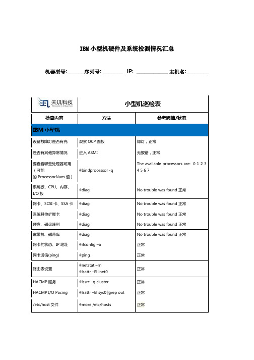
IBM小型机硬件及系统检测情况汇总
正常
HACMP 服务
#lssrc –g cluster
正常
HACMP I/O Pacing
#lsattr –El sys0 |grep out
正常
/etc/host文件
#more /etc/hosts
正常
HACMP 日志
#tail –f /tmp/hacmp.out
# sysdumpdev –l
正常
系统备份检查
做vg配置信息的备份
已备份
询问客户有否在系统变更后或每半年做系统备份
询问客户数据库及应用、应用数据是否定期有效
进行备份
系统性能检查
CPU
#topas
正常
Disk
#vmstat
正常
应用程序磁盘
#iostat
正常
交换区
#lsps -a
正常
#bindprocessor -q
The available processors are: 0 1 2 3 4 5 6 7
系统板、CPU、内存、I/O板
#diag
No trouble was found 正常
网卡、SCSI卡、SSA卡
#diag
No trouble was found 正常
系统其他扩展卡
#diag
No trouble was found 正常
硬盘、磁盘阵列
#diag
No trouble was found 正常
磁带机、磁带库
#diag
No trouble was found 正常
网卡的状态、IP地址
#ifconfig –a
正常
网卡通信(ping)
MLC 9000+ 说明书
保修
我们可以担保这些产品在出厂之前,在材料和工艺方面无任何功能缺陷,并且可以担保此类 产品在三年内符合相关说明手册资料中所提到的技术规范。 除此处及上述所提及的保修条例外,无任何其他明示或暗示保修。WEST 不会因任何特殊原 因对该产品的适销性和适用性做任何担保。
限制
对于任何意外损坏、后续损坏、特殊损坏或任何其他损坏,或者除上述所提及的任何维修或 更换之外的成本或费用,供应商概不承担责任。用户必须按照说明安装和维护产品。对于因 腐蚀性而造成的产品损坏,供应商没有保修责任。用户自己对于这些产品与其应用程序的适 用性负责。对于一个有效的保修声明,产品在保修期内进行返修必须向供应商支付运费。产 品必须进行适当包装,以免在运输过程中因静电放电或其他形式的危害导致产品受损。
MLC 9000+ 用户指南
MLC 9000+ 用户指南
59371-1
价格:
£11.00 €15.00 $15.00
ii
59327,第 1 期 – 2003 年 5 月 4 日
本安装、接线和操作手册中的信息可能会有所变动,恕不另行通知。 Copyright © 2004 年 5 月,Danaher ICG,保留所有权利。未经厂商书面许可,不得以任何 形式或通过任何方式在检索系统中复制、传播、改写或存储本出版物的任何部分,或者将本 出版物的任何部分翻译成任何其他语言。 注意:
ii
59327,第 1 期 – 2003 年 5 月 4 日
MLC 9000+ 用户指南
目录
目录
1 2 MLC 9000+ 系统概述 ................................................................................
跑马灯代码表
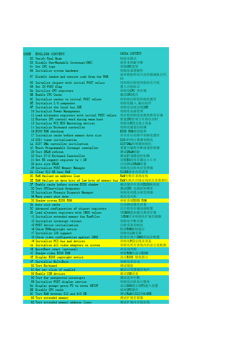
CODE ENGLISH CONTENT CHINA CONTENTO2Verify Real Mode校验实模式O3Disable Non-Maskable Internupt(NMI)放弃非屏蔽中断O4Get CPU type获得CPU类型O6Initialize system hardware 初始化系统硬件O7Disable shadow and execute code from the ROM放弃映射和从只读存储器执行代码 O8Initalize chipset with initial POST valucs用初始自检值初始化芯片组O9Set IN POST flag置入自检标示OA Initilize CPU registers初始化CPU 寄存器OB Enable CPU Cache激活CPU缓存OC Initialize caches to initial POST values用初始自检值初始化缓存OE Initialize I/O component初始化输入,输出组件OF Initialize the local bus IDE初始化局部总线IDE 10Initialize Power Management初始化电源管理11Load alternate registers with initial POST values用自检初始值加载替换寄存器12Restore CPU control word during warm boot恢复CPU控制字在热启动时13Initialize PCI BUS Mastering devices初始化PCI总线主设备14Initialize Keyboard controller初始化键盘控制器16BIOS ROM checksum BIOS ROM求校验和17Iinitalize cache before memory Auto size在内存自动排序初始化缓存188254 timer initialization8254时钟计数器初始化1A8237 DMA controller initilzation8237DMA控制器初始化1C Reset Programmable Intemupt conntpller重置可编程中断请求控制器20Test DRAM refresh测试DRAM刷新22Test 8742 Keyboard Conntroller测试8742键盘控制器24Set ES segment register to 4 GB设置ES段寄存器达4GB28Auto size DRAM自动测试DRAM容量29Initialize POST Memory Manager初始化自检内存管理器2A Clear 512 KB base RAM512KB基本内存清零2C RAM failure on address line RAM失败在某地址线2E RAM failure on data bits of low byte of memory bus RAM失败在存储总线低位某数据位 2F Enable cache before system BIOS shadow激活缓存在系统BIOS映射前32Test CPUbus-clock freguency测试CPU 总线时钟频率33Initialize Phoenix Dispatch Manager初始化凤凰分派管理器36Warm start shut down热启动关机38Shadow system BIOS ROM映射系统BIOS ROM3A Auto size cache自动测试缓存容量3C Advanced configuration of chipset registers芯片组寄存器高级配置3D Load altrnate registers with CMOS values用CMOS值加载交换寄存器41Initialize extended memory for RomPilot为ROM引导初始化扩展存储器42Initialize interrupt vectors初始化中断向量45POST device initialization自检设备初始化46Check ROMcopyright notice检查ROM版权提示47Initialize 120 support初始化120支援48Check video configuration against CMOS检查区别于CMOS的显存配置49Initialize PCI bus and devices初始化PCI总线及设备4A Initialize all video adapters in system初始化所有系统内的显示适配器 4B QuietBoot start (optional)冷启动开始4C Shadow video BIOS ROM映射ROM内显示BIOS4E Display BIOS copyright notice显示BIOS 版权提示4F Initialize MultiBoot初始化多启动52Test Keyboard测试键盘54Set key click if enabled激活后设置键控响声55Enable USB devices激活USB设备58Test for unexpected interrupts测试意外中断59Initialize POST display service初始化自检显示服务5A Display prompt press F2 to enter SETUP显示DOS提示按F2进入设置5B Disable CPU cache放弃CPU缓存5C Test RAM between 512 and 640 KB测试RAM从512至640KB 60Test extended memory测试扩展存储器62Test ectended memory address lines测试扩展内存地址线64Jump to UserPatch1跳至用户补丁区166Configure advanced cache registers配置高级缓存寄存器67Initialize Multi Processor APIC初始化多处理器APIC68Enable external and CPU caches激活外接和CPU缓存69Display system Management Mode (SMM)area显示系统管理模式区6A Display external L2 cache size 显示外接L2缓存容量6B Load custom defaults(optional)加载用户默认值6C Dislay shadow-area message显示映射区信息6E Display possible high address for UMB recover显示可能的高端地址为UMB恢复使用70Display error messages显示错误信息72Check for configuation errors检测配置偏差76Check for keyboard errors检测键盘错误7C Set up tard ware interrupt vectors设置硬件中断向量7D Initialize Intelligent System Monitoring初始化智能系统跟踪7E Initialize coprocessor if present如果存在,初始化协处理器80Disable onboard Super I/O ports and IRQS放弃板上的超级输入输出端口及IRQS 81Late POST device initialization最后自检设备的初始化82Detect and install extemal RS232 ports侦测安装外接RS232端口83Configure non-MCD IDE controllers配置NON-MCD IDE控制器84Detect and installextermal parallel ports侦测安装外接并行端口85Initialize PC-compatible PnP ISA devices初始化兼容PC即插即用ISA设备86Re-initialize onblard I/O Ports重初始化板上的输入输出端口87Configure Motherboard Configurable Devices(optional)配置M/B可配置设备88Initializ BIOS Data area BOIS数据区初始化89Enable mon-maskable inteerupts[NMIS]激活非屏蔽中断请求8A Initializ Extended Bios Data Area扩展BIOS数据区初始化8b Test and initialize PS/2 mouse测试和初始化PS/2端口8C Initialize floppy controller初始化软驱控制器8F Determine number of ATA drives (optional)测试ATA驱动器数量90Initialize hard-disk controllers初始化硬盘驱控制器91Initialize local-bus bard-disk countrollers初始化局部总线上的硬盘控制器92Jump to Userpatch2跳至用户补丁区93Build MPTABLE for multi-processor boards为多处理器板建立多处理器列表95Install CD-ROM for boot为启动安装CD-ROM96Clear hUge ES segment register清空大量ES段寄存器97Fix up Multi Procssor table设置多处理器列表98Scarch for option ROMs,One long,授索可选只读存储器,一长,二two short beeps on checksum failure短嗡鸣声,在校验失败时99Check for SMART Drive(optional)检查SMART驱动器9A Shadow option ROMs映射选定的只读存储器9C Set up power Management设置电源管理9D Initialize security engine(oprional)初始化安防措施9E Enable bardware interrupts激活硬件中断9F Determine number of ATA and SCDI drives 检测A/A和SCDI设备数量A0Set time or day设置时间和日期A2Check key lock检查锁定键A4Initialize typebatic rateA8Erase F2 prompt清除F2提示AA Scan for F2 key stroke扫描有无F2键按下AC Enter SETUP进入设置AE clear boot flag清除启动标志B0Check for errors检查错误B1Inform Rom pilot about the end of POST通知只读存储器在自检结束后引导系统 B2POST done-prepare to boot operating system自检结束准备起动系统B4One short beep before boot起动前一个短嗡鸣声B5Terminate QuietBoot(optional)结束冷启动B6Check passwont(potional)检验密码B7Initialize ACPIBIOS初始化ACPIBIOSB9Prepare Boot准备启动BA Initialize SMBIOS初始化SMBIOSBB Initialize PuP Option ROMs初 始化即插即用只读存储器BC Clear parity checkers清零奇偶校验检测BD Display MultiBoot menu显示多启动菜单BE Clear screen (Optional)清空显示屏BF Check virus and backup reminders检查病毒备份提示C0Try to boot with INT 19试用INT 19启动C1Initialize POST Error Manager初始化自检管理C2Initialize error logging初始化错误日志C3Initialize error display function初始化错误显示功能C4Initialize system error bandler初始化系统错误处理C5PnPnd dual CMOS(optional)C6Initialize note disk (optional)C7Initialize note dock lateC8Force check(optional)强行检查CC Redirect Int 10h to ENable remote serial video重指示INT 10去激活远程窜行显示 CD Re_map I/O and memory for PCMCIA重定位I/O和内存为PCMCIA卡CE Initialize digitize and display message初始化数字的显示信息D2Unknowm interrupt不明中断The followIng are for boot block in Flash ROME0Initialize the chipset初始化芯片组E1Initialize the bridge初始化桥E2Iinitalize the CPU初始化CPUE3Initialize system timer初始化系统时钟E4Initialize system I/0初始化系统输入输出口E5Check force reCovery boot检查强行恢复启动E6Checksum BIOSROM BIOS ROM求校验和E7Go to BIOS转向BIOSE8Set Hune Segment设置大量段寄存器E9Initialize Multi procssor初始化多处理器EA Initialize OEMspectal code初始化OEM专用代码EB Initialize PIC and DMA初始化PIC 和DMAEC Initialize Memory type初始化存储类型ED Initialize Memory size初始化存储容量EE Shadow Boot Block映射启动模块EF System memory test系统存储器测试F0Initilize intemupt vectors初始化中断向量F1Initilize Run Time Clock初始化运行时钟F2Initilize video初始化显示F3Initilize System Management Manager初始化系统管理的管理器F4Output one beep输出一个嗡鸣声F5Clear Huge Seginent清空大量段寄存器F6Boot to Mini DOS最小化DOS启动F7Boot to Full DOS完整DOS启动。
技嘉GA-Z270X-Gaming SOC主板使用手册说明书
Dec. 30, 2016Motherboard GA-Z270X-Gaming SOC目录清点配件 (6)选购配件 (6)GA-Z270X-Gaming SOC主板配置图 (7)第一章硬件安装 (9)1-1 安装前的注意事项 (9)1-2 产品规格 (10)1-3 安装中央处理器及散热风扇 (14)1-3-1 安装中央处理器(CPU) (14)1-3-2 安装散热风扇 (16)1-4 安装内存条 (17)1-4-1 双通道内存技术 (17)1-4-2 安装内存条 (18)1-5 安装扩展卡 (19)1-6 构建AMD CrossFire™/NVIDIA® SLI™系统 (20)1-7 后方设备插座介绍 (21)1-8 内建灯号、按钮及切换器 (23)1-9 更换音频放大器 (25)1-10 插座及跳线介绍 (26)第二章 BIOS 程序设置 (41)2-1 开机画面 (42)2-2 BIOS设定程序主画面 (43)2-3 M.I.T. (频率/电压控制) (45)2-4 System (系统信息) (57)2-5 BIOS (BIOS功能设定) (58)2-6 Peripherals (集成外设) (61)2-7 Chipset (芯片组设定) (64)2-8 Power (省电功能设定) (65)2-9 Save & Exit (储存设定值并结束设定程序) (67)第三章构建磁盘阵列 (69)3-1 设定SATA控制器模式 (69)3-2 安装SATA RAID/AHCI驱动程序及操作系统 (83)3-3 启动Intel® Optane™技术 (86)第四章驱动程序安装 (87)4-1 Drivers & Software (驱动程序及应用软件) (87)4-2 Application Software (软件应用程序) (88)4-3 Information (信息清单) (88)- 4 -第五章独特功能介绍 (89)5-1 BIOS更新方法介绍 (89)5-1-1 如何使用Q-Flash更新BIOS (89)5-1-2 如何使用@BIOS更新BIOS (92)5-2 APP Center (93)5-2-1 3D OSD (94)5-2-2 AutoGreen (95)5-2-3 BIOS Setup (96)5-2-4 Color Temperature (97)5-2-5 Cloud Station (98)5-2-6 EasyTune (103)5-2-7 Easy RAID (104)5-2-8 Fast Boot (107)5-2-9 Game Boost (108)5-2-10 Platform Power Management (109)5-2-11 RGB Fusion (110)5-2-12 Smart TimeLock (111)5-2-13 Smart Keyboard (112)5-2-14 Smart Backup (113)5-2-15 System Information Viewer (115)5-2-16 USB Blocker (116)5-2-17 USB DAC-UP 2 (117)5-2-18 V-Tuner (118)第六章附录 (119)6-1 音频输入/输出设定介绍 (119)6-1-1 2 / 4 / 5.1 / 7.1声道介绍 (119)6-1-2 S/PDIF输出设定 (121)6-1-3 麦克风录音设定 (122)6-1-4 语音录音机使用介绍 (124)6-2 疑难排解 (125)6-2-1 问题集 (125)6-2-2 故障排除 (126)6-3 除错灯号代码说明 (128)管理声明 (132)技嘉主板售后服务及质量保证卡 (134)技嘉科技全球服务网 (135)- 5 -清点配件5GA-Z270X-Gaming SOC主板- 1片5驱动程序光盘- 1片5使用手册- 1本5硬件安装指南- 1张5SATA排线- 4条5后方I/O设备挡板铁片- 1个5G Connector- 1个5后方I/O设备防尘盖- 1包5GC-SLI2P连接器- 1个上述附带配件仅供参考,实际配件请以实物为准,技嘉科技保留修改的权利。
cisco_ASA防火墙恢复初始化
cisco_ASA防火墙恢复初始化ASA 防火墙flash 被删防火墙不断启动Use BREAK or ESC to interrupt boot.Use SPACE to begin boot immediately.按下ESC进入监控模式监控模式下的显示和交换机路由器没有什么区别。
命令格式也大同小异只要大家变通一下就不难恢复。
rommon #1> ?Variables: Use "sync" to store in NVRAMADDRESS= local IP addressCONFIG= config file path/nameGATEWAY= gateway IP addressIMAGE= image file path/nameLINKTIMEOUT= Link UP timeout (seconds)PKTTIMEOUT= packet timeout (seconds)PORT= ethernet interface portRETRY= Packet Retry Count (Ping/TFTP)SERVER= server IP addressVLAN= enable/disable DOT1Q tagging on the selected portrommon #2> ADDRESS=192.168.0.2 (因为是TFFP上传,所以防火墙设置为客户机)rommon #3> GATEWAY=192.168.0.1 (网关)rommon #4> IMAGE=asa802-k8.bin (导入IOS的名称)rommon #5> SERVER=192.168.0.1 (服务器IP,也就是你的PC)rommon #6> sync (保存)Updating NVRAM Parameters...rommon #7> ping 192.168.0.1Sending 20, 100-byte ICMP Echoes to 192.168.0.1, timeout is 4 seconds:Success rate is 95 percent (19/20)确认线路是否连通,开启TFTP软件(这里说明下我测试是ASA5505 所以接的E0/0口。
DELL服务器通过sd卡安装系统(iDRAC-Use-vFlash-)
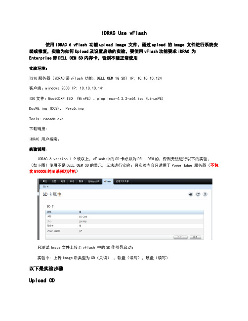
iDRAC Use vFlash使用iDRAC 6 vFlash 功能upload image 文件,通过upload 的image 文件进行系统安装或修复,实验为如何Upload及设置启动的实验,要使用vFlash功能要求iDRAC 为Enterprise带DELL OEM SD内存卡,否则不能正常使用实验环境:T310服务器(iDRAC带vFlash 功能、DELL OEM 1G SD)IP: 10.10.10.124客户端:windows 2003 IP: 10.10.10.141ISO文件:BootCDXP.ISO (WinPE)、ploplinux-4.2.2-x64.iso (LinuxPE)Dos98.img (DOS)、 Perc6.imgTools:racadm.exe下载链接:iDRAC 用户指南:实验说明:iDRAC 6 version 1.9或以上,vFlash中的SD卡必须为DELL OEM的,否则无法进行以下的实验,(如下图)使用不是DELL OEM SD的显示,无法进行实验;另实验内容只适用于Power Edge 服务器(不包含M1000E的M系列刀片机)只测试Image文件上传至vFlash 中的SD作引导启动;实验中:上传Image后类型为CD(只读),软盘(读写),硬盘(读写)以下是实验步骤Upload CD1.首先要登入 iDRAC Web 页面,默认用户名:root, 密码:calvin ;2.进入vFlash 界面,如第一次使用请在SD卡中初始化及启用vFlash功能;如下图3.完成以上步骤后,点击“从映像创建”进行Image文件上传;如下图4.点击上图的“应用”上传文件进程开始运行,并请等待至提示“已完成创建分区”的提示出现;如下图5.完成创建分区后点击“管理”,选中已附加并应用;如下图6.在完成应用后,可进行使用已上传的Image 文件进行启动,可以选择在iDRAC中的设置,设置为第一引导设备,选择一次性引导;如下图或开机时按F11,通过BIOS Boot Manager 的文件启动Image文件;如下图以下启动后的将以ISO文件启动;如下图7.附加后如正常进入操作系统,可在直接中以光驱形式显示,要取消则在iDRAC中取消附加;参考步骤5Upload Fopply1.Upload Fopply first boot;注:上传为软盘只能使用于First Boot ,不能用于安装操作系统过程中加载驱动,如加载阵列控制卡驱动;2.从“映像创建”文件为dos98.img,标签为DOS;如下图3.请确保上传完成100%;如下图4.将文件附加;如下图5.如显示如下断开提示,新附加的介质,iDRAC会中断所有已附加的介质并重新加载,故选择确定即可;如下图6.参考步骤6方式以附加的文件方式启动;7.启动后的显示;如下图8.在系统中的显示为可移设备而不是为A盘;如下图Upload HDD1.上传Image文件作为磁盘分区,标签为HDD,类型为硬盘;如下图2.上传完成;3.附加,新附加的介质,iDRAC会中断所有已附加的介质并重新加载,故选择确定即可;如下图4.在系统的显示为可移动磁盘,而不是本地磁盘;如下图命令模式上传ISO1.以命令模式上传ISO 到vFlash中;工具:racadm.exe命令参数:vflashpartition 子命令(create | delete | status | list)-i (索引1-16的数字)-o (卷标,六个字母或数字,不能带空格)-e (类型:Floppy、cddvd、HDD)-t(类型:empty 创建空白分区,image:使用上传的image创建分区)empty - 创建空白分区。