美国制动液标准 FMVSS-116-2002 DOT
FMVSS标准编号及内容

222
School Bus Passenger Seating and Crash Protection
动力操纵车窗系统
座椅安全带总成 座椅安全带总成固定点 儿童约束系统 儿童约束系统固定点 头枕 座椅系统 学童客车乘员座椅和 碰撞保护
203
Impact Protection for the Driver from the Steering 驾驶员免受转向控制系统
208 Occupant Crash Protection 214 Side Impact Protection 224 Rear Impact Protection 223 Rear Impact Guards
乘员在车内碰撞时的防护
乘员碰撞保护 侧碰撞保护 后碰撞保护 后碰撞保护
AntiFire Risks (Total 5)
103 Windshield Defrosting and Defogging Systems 104 Windshield Wiping and Washing Systems 111 Rearview Mirrors
105 Hydraulic and Electric Brake Systems
描述
控制器和显示器 摩托车的控制器和显示器 风窗玻璃除霜和除雾系统 风窗玻璃刮水和洗涤系统 后视镜 液压制动系统 制动软管 机动车制动液 气压制动系统 摩托车制动系统 轿车制动系统 新的充气轮胎 轮胎和轮辋选择 翻新充气轮胎 车辆(不包括轿车)用的 充气轮胎
机动车(不包括轿车)轮胎和轮辋 选择
新的轿车非充气轮胎
轮胎气压监控系统 警告装置
灯具,反射装置和辅助设备
Hood Latch and Theft Protection
美国DOT认证(FMVSS)
美国DOT认证2013-04-27 09:35 瑞诺标准DOT是美国交通部(US Department of Transportation)的英文缩写。
美国交通部成立于1967年,总部位于华盛顿,下设联邦公路管理局(FHWA)、联邦航空管理局(FAA)、联邦机动车安全管理局(FMCSA),海运管理局(MARAD)、全国公路交通安全管理局(NHTSA),总检察官办公室(OST)等部门。
在全美拥有 6 万名雇员。
它的职责是发展和完善与交通与运输相关的法规,对进入美国的各种交通工具和运输的危险物品做出一系列规定, 颁发证书等。
致力于维护交通安全,促进经济发展,以满足环境和国防的需求。
DOT认证制度即联邦机动车辆安全标准(FMVSS)使于1968年,由美国交通部的全国公路交通安全管理局(NHTSA)负责制定/修订标准并予实施。
DOT认证是强制性认证,即所有在美国销售的机动车及配件产品都必须通过DOT认证,拥有DOT标志。
经过三十多年的实际应用,DOT认证也由刚开始时仅在美国国内实行而逐渐延展到整个北美地区。
如今,在北美消费者眼里,模压在胎侧上的DOT代码是一种对质量作出承诺的标签,换言之是由轮胎制造商出具的质量保证书,因此对于市场上有DOT 代码的轮胎,其售价比没有DOT代码的轮胎要高的现象,他们认为理所当然,也乐于接受。
在机动车和零配件制造商眼里,DOT代码代表着一种责任——该产品无条件满足美国联邦机动车辆安全标准(FMVSS)有关最低性能要求和产品标识要求的所有适用条款。
其实DOT认证就是一种市场游戏规则,它体现着"自由贸易、承担责任、分享利益"的商业精神。
当然,对于机动车和零配件制造商而言,DOT认证与机动车和零配件产品进入北美市场的“敲门砖”和“准入证”具有同等重要的意义。
认证范围:美国法律规定,进入美国销售和使用的汽车、摩托车、电动车整车及零部件(制动软管、车灯、反射镜、制动液、轮胎和轮辋、玻璃、头盔,用于交通工具的油漆、化工涂料等)、轮船,飞机,卡车,油罐车,电动车,轮胎,气囊等产品必须通过美国交通部的DOT认证。
汽车制动液的正确选用

汽车制动液的正确选用满文水瓶摘要:制动液选用是否正确,直接影响汽车制动系统工作的可靠性和汽车行驶的安全性。
笔者结合新的国家标准G B12981-2012在对制动液的质量分级对比的基础上,提出制动液正确选用的方法和注意事项。
关键词:制动液正确选用汽车制动液(俗称制动液、刹车油),是汽车液压制动系统中所用的传递压力以制止车轮转动的工作介质。
制动液选用是否正确,直接影响汽车制动系统工作的可靠性和汽车行驶的安全性。
正确选用制动液,除了要熟悉汽车的使用条件、制动系统的结构特点、橡胶密封材料的特性外,还应熟悉各种牌号制动液的性能。
一、制动液的质量分级随着汽车技术的发展,为了适应和提高汽车制动的可靠性。
从1989年,国家开始执行GB10830-1989《机动车制动液使用技术条件》、GB12981-1991《HZY 2、HZY 3、HZY 4合成制动液》、GB12981-2003《机动车制动液》标准,2012年5月11日国家颁布了新的标准GB12981-2012《机动车制动液》。
按使用工况温度和黏度要求的不同将合成制动液分为HZY3、HZY4、HZY5、HZY6四个级别。
序号越大、其平衡回流沸点越高,高温抗气阻性越强,行车制动安全性越好。
HZY3级制动液具有优良的低温流动性能和良好的抗高温气阻性能,相当于ISO4925(国际标准)和DOT3(美国车辆安全标准)水平,能满足国产轿车、微型车、进口货车的使用要求。
HZY4级制动液具有良好的低温流动性能和优良的抗高温气阻性能,相当于DOT4水平,能满足新型高级轿车的使用要求。
HZY5级制动液具有良好的低温流动性能和优异的抗高温气阻性能,相当于DOT5.1水平,仅供有特殊要求的车辆。
二、对制动液的使用性能要求由于制动液在液压制动中肩负着重要作用,故要求其安全可靠、质量高、性能好,良好的制动液必须具备以下性能:1.高温抗气阻性,制动液的沸点应在205℃以上,吸湿温度要高,在高温下不产生气阻,在常温下吸湿水分要少。
FMVSS标准编号及内容

罩盖锁装置 防盗装置 学童客车行人安全装置 加速器控制系统 变速器换挡杆顺序,起动机互锁机 构和变速器制动效能 动力操纵车窗系统 座椅安全带总成 座椅安全带总成固定点 儿童约束系统 儿童约束系统固定点 头枕 座椅系统 学童客车乘员座椅和 碰撞保护
Seat Belt and Restraint System
210 213 225 202
Seating System and Head Restraints
207 222 203 204
Impact Protection for the Driver from the Steering 驾驶员免受转向控制系统 Control System 伤害的碰撞保护 Steering Control Rearward Displacement Occupant Protection in Interior Impact Occupant Crash Protection Side Impact Protection Rear Impact Protection Rear Impact Guards 转向控制装置的向后位移 乘员在车内碰撞时的防护 乘员碰撞保护 侧碰撞保护 后碰撞保护 后碰撞保护
Hood Latch and Theft Protection School Bus Pedestrian Safety Accelerator ControlSystems, Power-Operated Window,Transmissi on Braking
113 114 131 124 102 118 209
Hydraulic and Air Brake Systems
116 121 122 135
Active Safety (Total 26)
美国联邦机动车安全系统实用实用标准FMVSS

86-A
1977及其后型号年的轻型车辆,轻型货车,重型柴油车排污法规一般规定
63
86-E
1978及其后型号年新摩托车排气污染法规的一般规定
64
86-F
1987及其后型号年新摩托车排气污染规程试验规程
65
205
交通噪声污染的控制设备
66
205-B
中型和重型载货汽车
67
205-E
摩托车排气系统
68
325
33
FMVSS204
转向控制装置的向后位移
34
FMVSS205
玻璃材料
35
FMVSS206
车门锁及车门固定组件
36
FMVSS207
座椅系统
37
FMVSS208
乘员碰撞保护
38
FMVSS209
座椅安全带总成
39
FMVSS210
座椅安全带总成固定点
40
FMVSS211
车轮螺母、轮辐和轮彀盖
41
FMVSS212
风窗玻璃的安装
42
FMVSS213
儿童约束系统
43
FMVSS214
侧ቤተ መጻሕፍቲ ባይዱ强度
44
FMVSS215
(备用)
45
FMVSS216
轿车车顶抗压强度
46
FMVSS217
客车紧急岀口及车窗的固定与松放
47
FMVSS218
摩托车头盔
48
FMVSS219
风窗玻璃区的干扰
45
FMVSS220
学童客车侧倾的防护
FMVSS221
翻新充气轮胎
18
FMVSS118
《汽车运行材料》 汽车制动液

4.与橡胶的配伍性 制动液与橡胶的配伍性通过橡胶皮碗试验评定。
在规定的试验条件下(皮碗规格、材料、试验温.25mm,将皮碗浸人制动液中,试验条件有 两种:①120℃、70h;②70℃ 、70h。分别进行。 然后测定橡胶皮碗的体积变化、直径变化、硬度变 化和外观变化。 5.稳定性
沸点测定仪:
1.冷凝器 2.温度计 3.圆底烧瓶
(2)湿平衡回流沸点
制动液在使用过程会吸收周围的水气使沸点 (称为湿平衡回流沸点或湿沸点)显著下降。
GB12981-2003《附表C 制动液湿平衡回流沸点 测定法》规定了汽车制动液的湿平衡回流沸点的测 定方法。湿平衡回流沸点是在60mL的制动液试样中 加入2.1mL的蒸馏水,混合均匀,然后按照测定平衡 回流沸点的方法进行测定。
(10)更换制动液后,应放出制动管路中的空 气,放气的基本原则是“由远而近,由上而下”, 逐个进行。
制动液的液体稳定性包括高温稳定性和化学稳 定性两个方面。该指标主要用来反映制动液在一定 试验条件下的物理和化学稳定性能。
制动液的高温稳定性检验方法是将60mL的制动液 试样加热到185℃,恒温2h,在试样内气压与大气压平 衡的条件下,再升温测定其平衡回流沸点,用试样的 原平衡回流沸点与加热后平衡回流沸点的差值来评定 制动液的高温稳定性。
制动液的化学稳定性检验方法是将30mL的制动液 试样与30mL相溶性液体混合后,测定混合液的平衡回 流沸点,用开始沸腾回流后第一分钟内混合试样的最 高温度与随后测得的平均沸点的差值来评定制动液的 化学稳定性。
6.溶水性
要求制动液吸水后能与水互溶,不产生分离和沉 淀,不能因为有水而变质。
制动液的溶水性通过溶水性试验来评定。
几种常见的制动液产品
任务三 汽车制动液的选用
车辆刹车油的选择和使用
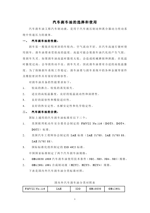
汽车刹车油的选择和使用汽车刹车油又称汽车制动液,是用于汽车液压制动和离合器动力传动系统中传递压力的液体。
一、汽车刹车油的性能:刹车泵一般装在较密封的车轮内,空气流动不好,在汽车高速行驶时使用刹车,刹车油要承受很高的温度。
高温可能会使刹车油汽化而产生气阻,使刹车失灵。
如果刹车油高温时黏度太低,会造成机械磨损和泄露,在低温时黏度过高,会导致传动不良、刹车失灵,因此刹车油要有合适的高低温黏度。
为了保障刹车系统工作稳定,刹车油要与刹车系统中的各种金属零部件及橡胶密封件具有很好的相容性。
对刹车油具备的性能要求如下:1.较高的沸点,较低的蒸发损失。
2.适宜的高低温黏度,良好的低温流动性和润滑性。
3.良好的混容性和橡胶适应性。
4.良好的热安定性、水解安定性和化学稳定性。
二、汽车刹车油的分类:国际上通用的汽车刹车油标准有以下三个:1.美国联邦机动车安全委员会制定的FMVSS No.116(DOT3、DOT4、DOT5)标准。
2.美国汽车工程师协会制定的SAE标准(SAE J1703、SAE J1703-88、SAE J1705-88)。
3.国际标准化组织制定的ISO 4925标准。
中国国家标准制定了两个汽车刹车油规格:1.GB10830-1989汽车刹车油使用技术条件(JG2、JG3、JG4、JG5)规格。
2.GB12981-1991合成制动液(HZY2、HZY3、HZY4)规格。
下表是国内外汽车刹车油分类标准对照:国内外汽车刹车油分类对照表三、汽车刹车油的选择:现在汽车的设计时速越来越高,结构设计越来越紧凑,这就使刹车油的工作温度很高而散热通风条件较差,因此对刹车油的性能要求越来越高。
目前使用的刹车油一般都是合成刹车油。
刹车油的选择首先根据汽车生产厂家使用说明书推荐的规格,尽量满足其要求。
在没有说明书的情况下,选择时可参考以下几点:1.JG2级刹车油:适用于设计时速不太高的国产小型车辆的液压制动系统。
2.JG3级刹车油:适用于国产轿车和中、重型卡车的液压制动系统。
dot制动液标准
制动液,也被称为刹车油,是汽车、摩托车和其他机械设备中用于传递制动压力的关键液体。
它的主要功能是将驾驶员施加在制动踏板上的力量转化为液压能,从而推动制动器夹紧刹车盘或刹车鼓,实现车辆的减速或停止。
关于制动液的标准,各国和地区可能有所不同,但大多数标准都是基于国际标准化组织(ISO)和美国汽车工程师协会(SAE)的规定。
以下是一些常见的制动液标准:1. ISO 4925:这是由ISO制定的全球通用的制动液标准。
根据这个标准,制动液被分为DOT 3、DOT 4和DOT 5.1三个等级。
DOT 3和DOT 4主要用于乘用车,而DOT 5.1则主要用于商用车和重型设备。
2. DOT 3:这是美国国家公路交通安全管理局(NHTSA)制定的一种制动液标准。
DOT 3制动液的性能在-40℃到180℃的温度范围内都能保持稳定。
3. DOT 4:这是美国汽车制造商协会(AAMA)推荐的一种制动液标准。
DOT 4制动液的性能在-40℃到260℃的温度范围内都能保持稳定。
4. DOT5.1:这是美国汽车制造商协会(AAMA)推荐的一种高性能制动液标准。
DOT 5.1制动液的性能在-40℃到340℃的温度范围内都能保持稳定。
在选择制动液时,应确保其符合车辆制造商的推荐标准。
如果不确定应该使用哪种制动液,可以查阅车辆的用户手册或联系车辆制造商。
此外,还应定期更换制动液,以确保其性能不会因长时间使用而下降。
一般来说,制动液的更换周期为两年或四万公里,具体取决于车辆的使用情况和制动液的类型。
总的来说,制动液是汽车安全系统中的重要组成部分,其性能直接影响到车辆的制动效果和安全性。
因此,选择和使用正确的制动液是非常重要的。
- 1、下载文档前请自行甄别文档内容的完整性,平台不提供额外的编辑、内容补充、找答案等附加服务。
- 2、"仅部分预览"的文档,不可在线预览部分如存在完整性等问题,可反馈申请退款(可完整预览的文档不适用该条件!)。
- 3、如文档侵犯您的权益,请联系客服反馈,我们会尽快为您处理(人工客服工作时间:9:00-18:30)。
49 CFR Ch. V (10–1–02 Edition)§571.115§571.115[Reserved]§571.116Standard No. 116; Motor ve-hicle brake fluids.S1. Scope. This standard specifies re-quirements for fluids for use in hydrau-lic brake systems of motor vehicles, containers for these fluids, and labeling of the containers.S2. Purpose. The purpose of this standard is to reduce failures in the hy-draulic braking systems of motor vehi-cles which may occur because of the manufacture or use of improper or con-taminated fluid.S3. Application. This standard applies to all fluid for use in hydraulic brake systems of motor vehicles. In addition, S5.3 applies to passenger cars, multi-purpose passenger vehicles, trucks, buses, trailers, and motorcycles.S4. Definitions.Blister means a cavity or sac on the surface of a brake cup.Brake fluid means a liquid designed for use in a motor vehicle hydraulic brake system in which it will contact elastomeric components made of sty-rene and butadiene rubber (SBR), ethylene and propylene rubber (EPR), polychloroprene (CR) brake hose inner tube stock or natural rubber (NR). Chipping means a condition in which small pieces are missing from the outer surface of a brake cup.Duplicate samples means two samples of brake fluid taken from a single packaged lot and tested simulta-neously.Hydraulic system mineral oil means a mineral-oil-based fluid designed for use in motor vehicle hydraulic brake sys-tems in which the fluid is not in con-tact with components made of SBR, EPR or NR.Packager means any person who fills containers with brake fluid that are subsequently distributed for retail sale. Packaged lot is that quantity of brake fluid shipped by the manufacturer to the packager in a single container, or that quantity of brake fluid manufac-tured by a single plant run of 24 hours or less, through the same processing equipment and with no change in in-gredients.Scuffing means a visible erosion of a portion of the outer surface of a brake cup.A silicone base brake fluid (SBBF) is a brake fluid which consists of not less than 70 percent by weight of a diorgano polysiloxane.Sloughing means degradation of a brake cup as evidenced by the presence of carbon black loosely held on the brake cup surface, such that a visible black streak is produced when the cup, with a 500±10 gram deadweight on it, is drawn base down over a sheet of white bond paper placed on a firm flat sur-face.Stickiness means a condition on the surface of a brake cup such that fibers will be pulled from a wad of U.S.P. ab-sorbent cotton when it is drawn across the surface.S5. Requirements. This section speci-fies performance requirements for DOT 3, DOT 4 and DOT 5 brake fluids; re-quirements for brake fluid certifi-cation; and requirements for container sealing, labeling and color coding for brake fluids and hydraulic system min-eral oils. Where a range of tolerances is specified, the brake fluid shall meet the requirements at all points within the range.S5.1Brake fluid. When tested in ac-cordance with S6, brake fluids shall meet the following requirements:S5.1.1Equilibrium reflux boiling point (ERBP). When brake fluid is tested ac-cording to S6.1, the ERBP shall not be less than the following value for the grade indicated:(a) DOT 3: 205 °C. (401 °F.).(b) DOT 4: 230 °C. (446 °F.).(c) DOT 5: 260 °C. (500 °F.).S5.1.2Wet ERBP. When brake fluid is tested according to S6.2, the wet ERBP shall not be less than the fol-lowing value for the grade indicated:(a) DOT 3: 140 °C. (284 °F.).(b) DOT 4: 155 °C. (311 °F.).(c) DOT 5: 1 180 °C. (356 °F.).S5.1.3. Kinematic viscosities. When brake fluid is tested according to S6.3, the kinematic viscosities in square millimeters per second at stated tem-peratures shall be neither less than 1.5 mm2/s at 100 °C. (212 °F.) nor more than the following maximum value for the grade indicated:(a) DOT 3: 1,500 mm2/s at minus 40 °C. (minus 40 °F.).(b) DOT 4: 1,800 mm2/s at minus 40 °C. (minus 40 °F.).Nat’l Highway Traffic Safety Admin., DOT§571.116 (c) DOT 5: 900 mm2/s at minus 40 °C.(minus 40 °F.).S5.1.4pH value. When brake fluid,except DOT 5 SBBF, is tested accordingto S6.4, the pH value shall not be lessthan 7.0 nor more than 11.5.S5.1.5Brake fluid stability.S5.1.5.1High-temperature stability.When brake fluid is tested according toS6.5.3 the ERBP shall not change bymore than 3 °C. (5.4 °F.) plus 0.05° foreach degree that the ERBP of the fluidexceeds 225 °C. (437 °F.).S5.1.5.2Chemical stability. Whenbrake fluid, except DOT 5 SBBF, istested according to S6.5.4, the changein temperature of the refluxing fluidmixture shall not exceed 3.0 °C (5.4 °F.)plus 0.05° for each degree that theERBP of the fluid exceeds 225 °C (437°F.).S5.1.6Corrosion. When brake fluid istested according to S6.6—(a) The metal test strips shall notshow weight changes exceeding thelimits stated in Table I.T ABLE ITest strip materialMaximum permissible weight change, mg./sq. cm. of sur-faceSteel, tinned iron, cast iron.................................0.2 Aluminum.. (1)Brass, copper (4)(b) Excluding the area of contact (13±1 mm. (1⁄2±1⁄32inch) measured from the bolt hole end of the test strip), the metal test strips shall not show pitting or etching to an extent discernible without magnification;(c) The water-wet brake fluid at the end of the test shall show no jelling at 23±5 °C (73.4±9 °F.);(d) No crystalline deposit shall form and adhere to either the glass jar walls or the surface of the metal strips;(e) At the end of the test, sedimenta-tion of the water-wet brake fluid shall not exceed 0.10 percent by volume;(f) The pH value of water-wet brake fluid, except DOT 5 SBBF, at the end of the test shall not be less than 7.0 nor more than 11.5;(g) The cups at the end of the test shall show no disintegration, as evi-denced by blisters or sloughing;(h) The hardness of the cup shall not decrease by more than 15 International Rubber Hardness Degrees (IRHD); and(i) The base diameter of the cups shall not increase by more than 1.4 mm. (0.055 inch).S5.1.7Fluidity and appearance at low temperature. When brake fluid is tested according to S6.7, at the storage tem-perature and for the storage times given in Table II—(a) The fluid shall show no sludging, sedimentation, crystallization, or stratification;(b) Upon inversion of the sample bot-tle, the time required for the air bubbleto travel to the top of the fluid shall not exceed the bubble flow times shownin Table II; and(c) On warming to room temperature, the fluid shall resume the appearance and fluidity that it had before chilling.T ABLE II—F LUIDITY AND A PPEARANCE AT L OWT EMPERATURESStorage temperatureStoragetime(hours)Maximumbubbleflow time(seconds) Minus 40±2 °C. (minus 40±3.6 °F.) 144±4.010 Minus 50±2 °C. (minus 58±3.6 °F.) 6±0.235S5.1.8Evaporation. When brake fluidis tested according to S6.8—(a) The loss by evaporation shall not exceed 80 percent by weight;(b) The residue from the brake fluid after evaporation shall contain no pre-cipitate that remains gritty or abra-sive when rubbed with the fingertip; and(c) The residue shall have a pour point below minus 5 °C. (+23 °F.).S5.1.9Water tolerance. (a) At low tem-perature. When brake fluid is tested ac-cording to S6.9.3(a)—(1) The fluid shall show no sludging, sedimentation, crystallization, or stratification;(2) Upon inversion of the centrifuge tube, the air bubble shall travel to the top of the fluid in not more than 10 sec-onds;(3) If cloudiness has developed, the wet fluid shall regain its original clar-ity and fluidity when warmed to room temperature; and(b) At 60 °C. (140 °F.). When brake fluidis tested according to S6.9.3(b)—49 CFR Ch. V (10–1–02 Edition)§571.116(1) The fluid shall show no stratifica-tion; and(2) Sedimentation shall not exceed 0.15 percent by volume after centrifuging.S5.1.10Compatibility.(a) At low temperature. When brake fluid is tested according to S6.10.3(a), the test specimen shall show no sludging, sedimentation, or crystalliza-tion. In addition, fluids, except DOT 5 SBBF, shall show no stratification.(b) At 60 °C. (140 °F.). When brake fluid is tested according to S6.10.3(b)—(1) Sedimentation shall not exceed 0.05 percent by volume after centrifuging; and(2) Fluids, except DOT 5 SBBF, shall show no stratification.S5.1.11Resistance to oxidation. When brake fluid is tested according to S6.11—(a) The metal test strips outside the areas in contact with the tinfoil shall not show pitting or etching to an ex-tent discernible without magnification; (b) No more than a trace of gum shallbe deposited on the test strips outside the areas in contact with the tinfoil;(c) The aluminum strips shall not change in weight by more than 0.05 mg./sq. cm.; and(d) The cast iron strips shall not change in weight by more than 0.3 mg./ sq. cm.S5.1.12Effects on cups. When brake cups are subjected to brake fluid in ac-cordance with S6.12—(a) The increase in the diameter of the base of the cups shall be not less than 0.15 mm. (0.006 inch) or more than1.40 mm. (0.055 inch);(b) The decrease in hardness of the cups shall be not more than 10 IRHD at70 °C. (158 °F.) or more than 15 IRHD at 120 °C. (248 °F.), and there shall be no increase in hardness of the cups; and(c) The cups shall show no disintegra-tion as evidenced by stickiness, blis-ters, or sloughing.S5.1.13Stroking properties. When brake fluid is tested according to S6.13—(a) Metal parts of the test system shall show no pitting or etching to an extent discernible without magnifica-tion; (b) The change in diameter of anycylinder or piston shall not exceed 0.13 mm. (0.005 inch);(c) The average decrease in hardness of seven of the eight cups tested (six wheel cylinder and one master cylinder primary) shall not exceed 15 IRHD. Not more than one of the seven cups shall have a decrease in hardness greater than 17 IRHD;(d) None of the eight cups shall be in an unsatisfactory operating condition as evidenced by stickiness, scuffing, blisters, cracking, chipping, or other change in shape from its original ap-pearance;(e) None of the eight cups shall show an increase in base diameter greater than 0.90 mm (0.035 inch);(f) The average lip diameter set of the eight cups shall not be greater than65 percent.(g) During any period of 24,000 strokes, the volume loss of fluid shall not exceed 36 milliliters;(h) The cylinder pistons shall not freeze or function improperly through-out the test;(i) The total loss of fluid during the 100 strokes at the end of the test shall not exceed 36 milliliters;(j) The fluid at the end of the test shall show no formation of gels;(k) At the end of the test the amount of sediment shall not exceed 1.5 percent by volume; and(l) Brake cylinders shall be free of de-posits that are abrasive or that cannot be removed when rubbed moderately with a nonabrasive cloth wetted with ethanol.S5.1.14 Fluid color. Brake fluid and hydraulic system mineral oil shall be of the color indicated:DOT 3, DOT 4, and DOT 5.1 non-SBBF—color-less to amber.DOT 5 SBBF—purple.Hydraulic system mineral oil—green.S5.2Packaging and labeling require-ments for motor vehicle brake fluids.S5.2.1Container sealing. Each brake fluid or hydraulic system mineral oil container with a capacity of 177 mL or more shall be provided with a reseal-able closure that has an inner seal im-pervious to the packaged brake fluid. The container closure shall include a tamper-proof feature that will either be destroyed or substantially alteredNat’l Highway Traffic Safety Admin., DOT§571.116when the container closure is initially opened.S5.2.2Certification, marking, and la-beling.S5.2.2.1Each manufacturer of a DOT grade brake fluid shall furnish to each packager, distributor, or dealer to whom he delivers brake fluid, the fol-lowing information:(a) A serial number identifying the production lot and the date of manu-facture of the brake fluid.(b) The grade (DOT 3, DOT 4, DOT 5)of the brake fluid. If DOT 5 grade brake fluid , it shall be further distinguishedas ‘‘DOT 5 SILICONE BA SE’’ or ‘‘DOT5.1 NON-SILICONE BASE.’’(c) The minimum wet boiling point in Fahrenheit of the brake fluid.(d) Certification that the brake fluid conforms to §571.116.S5.2.2.2Each packager of brake fluid shall furnish the information specifiedin paragraphs (a) through (g) of thisS5.2.2.2 by clearly marking it on each brake fluid container or on a label (labels) permanently affixed to the con-tainer, in any location except a remov-able part such as a lid. After being sub-jected to the operations and conditions specified in S6.14, the information re-quired by this section shall be legibleto an observer having corrected visual acuity of 20/40 (Snellen ratio) at a dis-tance of 305 mm, and any label affixedto the container in compliance with this section shall not be removable without its being destroyed or defaced. (a) Certification that the brake fluid conforms to §571.116.(b) The name of the packager of the brake fluid, which may be in code form. (c) The name and complete mailing address of the distributor.(d) A serial number identifying the packaged lot and date of packaging.(e) Designation of the contents as ‘‘DOT—MOTOR VEHICLE BR A KE FLUID’’ (Fill in DOT 3, DOT 4, DOT 5 SILICONE BASE, or DOT 5.1 NON-SIL-ICONE BASE as applicable).(f) The minimum wet boiling point in Fahrenheit of the DOT brake fluid in the container.(g) The following safety warnings in capital and lower case letters as indi-cated: (1) FOLLOW VEHICLE MA NUFA C-TURER’S RECOMMENDA TIONS WHEN ADDING BRAKE FLUID.(2) KEEP BRA KE FLUID CLEA NA ND DRY. Contamination with dirt, water, petroleum products or other ma-terials may result in brake failure orcostly repairs.(3) STORE BRA KE FLUID ONLY INITS ORIGINA L CONTA INER. KEEP CONTA INER CLEA N A ND TIGHTLY CLOSED TO PREVENT A BSORPTIONOF MOISTURE.(4) CAUTION: DO NOT REFILL CON-TA INER, A ND DO NOT USE FOR OTHER LIQUIDS. (Not required for containers with a capacity in excess of19 L.)S5.2.2.3Each packager of hydraulic system mineral oil shall furnish the in-formation specified in paragraphs (a) through (e) of this S5.2.2.3 by clearly marking it on each brake fluid con-tainer or on a label (labels) perma-nently affixed to the container, in any location except a removable part suchas a lid. A fter being subjected to the operations and conditions specified inS6.14, the information required by this section shall be legible to an observer having corrected visual acuity of 20/40 (Snellen ratio) at a distance of 305 mmand any label affixed to the containerin compliance with this section shallnot be removable without its being de-stroyed or defaced.(a) The name of the packager of the hydraulic system mineral oil, whichmay be in code form.(b) The name and complete mailing address of the distributor.(c) A serial number identifying the packaged lot and date of packaging.(d) Designation of the contents as‘‘HYDR A ULIC SYSTEM MINER A L OIL’’ in capital letters at least 3 mmhigh.(e) The following safety warnings incapital and lower case letters as indi-cated:(1) FOLLOW VEHICLE MA NUFA C-TURER’S RECOMMENDA TIONS WHEN ADDING HYDRAULIC SYSTEM MINERAL OIL.(2) Hydraulic System Mineral Oil isNOT COMPA TIBLE with the rubber components of brake systems designedfor use with DOT brake fluids.49 CFR Ch. V (10–1–02 Edition)§571.116(3) KEEP HYDR ULIC SYSTEM MINERAL OIL CLEAN. Contamination with dust or other materials may re-sult in brake failure or costly repair. (4) CAUTION: STORE HYDRA ULIC SYSTEM MINERAL OIL ONLY IN ITS ORIGINA L CONTA INER. KEEP CON-T A INER CLE A N A ND TIGHTLY CLOSED. DO NOT REFILL CON-TA INER OR USE OTHER LIQUIDS. (The last sentence is not required for containers with a capacity in excess of 19 L.)S5.2.2.4 If a container for brake fluid or hydraulic system mineral oil is notnormally visible but designed to beprotected by an outer container or car-ton during use, the outer container or carton rather than the inner container shall meet the labeling requirements of S5.2.2.2 or S5.2.2.3, as appropriate.S5.3Motor vehicle requirement. Each passenger car, multipurpose passenger vehicle, truck, bus, trailer, and motor-cycle that has a hydraulic brake sys-tem shall be equipped with fluid that has been manufactured and packaged in conformity with the requirements of this standard.S6. Test procedures.S6.1Equilibrium reflux boiling point. Determine the ERBP of a brake fluid by running duplicate samples accord-ing to the following procedure and averaging the results.S6.1.1Summary of procedure. Sixty milliliters (ml.) of brake fluid are boiled under specified equilibrium con-ditions (reflux) at atmospheric pressure in a 100-ml. flask. The average tem-perature of the boiling fluid at the end of the reflux period, corrected for vari-ations in barometric pressure if nec-essary, is the ERBP.S6.1.2Apparatus. (See Figure 1) The test apparatus shall consist of —(a) Flask. (See Figure 2) A 100-ml.round-bottom, short-neck heat-resist-ant glass flask having a neck with a19⁄38standard taper, female ground-glass joint and a side-entering tube, with an outside diameter of 10 millime-ters (mm.), which centers the ther-mometer bulb in the flask 6.5 mm. from the bottom;(b) Condenser. A water-cooled, reflux, glass-tube type, condenser having a jacket 200 mm. in length, the bottomend of which has a 19⁄38standard-taper, drip-tip, male ground-glass joint; (c) Boiling stones. Three clean, unusedsilicon carbide grains (approximately 2 mm. (0.08 inch) in diameter, grit No. 8); (d) Thermometer. Standardized cali-brated partial immersion (76 mm.), solid stem, thermometers conforming to the requirements for an ASTM 2C or 2F, and an A STM 3C or 3F thermom-eter; and (e) Heat source. Variable autotransformer-controlled heatingmantle designed to fit the flask, or an electric heater with rheostat heat con-trol.F IG . 1. B OILING P OINT T EST A PPARATUSNat’l Highway Traffic Safety Admin., DOT§571.116F IG. 2. D ETAIL OF100 ML S HORT-N ECK F LASKS6.1.3Preparation of apparatus. (a) Thoroughly clean and dry all glass-ware.(b) Insert thermometer through the side tube until the tip of the bulb is 6.5 mm. (1⁄4inch) from the bottom center of the flask. Seal with a short piece of natural rubber, EPDM, SBR, or butyl tubing.(c) Place 60±1 ml. of brake fluid and the silicon carbide grains into the flask.(d) Attach the flask to the condenser. When using a heating mantle, place the mantle under the flask and support it with a ring-clamp and laboratory-type stand, holding the entire assembly in place by a clamp. When using a rheo-stat-controlled heater, center a stand-ard porcelain or hard asbestos refrac-tory, having a diameter opening 32 to 38 mm., over the heating element and mount the flask so that direct heat is applied only through the opening in the refractory. Place the assembly in an area free from drafts or other types of sudden temperature changes. Con-nect the cooling water inlet and outlet tubes to the condenser. Turn on the cooling water. The water supply tem-perature shall not exceed 28 °C. (82.4 °F.) and the temperature rise through the condenser shall not exceed 2 °C. (3.6 °F.).S6.1.4Procedure. A pply heat to the flask so that within 10±2 minutes the fluid is refluxing in excess of 1 drop per second. The reflux rate shall not exceed 5 drops per second at any time. Imme-diately adjust the heating rate to ob-tain an equilibrium reflux rate of 1 to 2 drops per second over the next 5±2 minutes. Maintain this rate for an ad-ditional 2 minutes, taking four tem-perature readings at 30–second inter-vals. Record the average of these as the observed ERBP. If no reflux is evident when the fluid temperature reaches 260 °C (500 °F), discontinue heating and re-port ERBP as in excess of 260 °C (500 °F).S6.1.5Calculation. (a) Thermometer inaccuracy. Correct the observed ERBP by applying any correction factor ob-tained in standardizing the thermom-eter.(b) Variation from standard barometric pressure. A pply the factor shown in Table III to calculate the barometric pressure correction to the ERBP.T ABLE III—C ORRECTION FOR B AROMETRICP RESSUREObserved ERBP corrected forthermometer inaccuracyCorrection per 1 mmdifference in pressure a°C. (°F.)100 °C. (212 °F.) to 190 °C. (374°F.).............................................0.039(0.07) Over 190 °C. (374 °F.)..................0.04(0.08)a To be added in case barometric pressure is below 760 mm.; to be subtracted in case barometric pressure is above 670 mm.(c) If the two corrected observed ERBP’s agree within 2 °C. (4 °C. for brake fluids having an ERBP over 230 °C./446 °F.) average the duplicate runs as the ERBP; otherwise, repeat the en-tire test, averaging the four corrected observed values to determine the origi-nal ERBP.S6.2Wet ERBP. Determine the wet ERBP of a brake fluid by running du-plicate samples according to the fol-lowing procedure.S6.2.1.Summary of procedure. A 350 ml. sample of the brake fluid is hu-midified under controlled conditions; 350 ml. of SA E triethylene glycol monomethyl ether, brake fluid grade, referee material (TEGME) as described in appendix E of SA E Standard J1703 Nov. 83, ‘‘Motor Vehicle Brake Fluid,’’November 1983, is used to establish the end point for humidification. After hu-midification, the water content and49 CFR Ch. V (10–1–02 Edition)§571.116ERBP of the brake fluid are deter-mined.S6.2.2Apparatus for humidification. (See Figure 3).Test apparatus shall consist of—(a) Glass jars. Four SAE RM–49 corro-sion test jars or equivalent screwtop, straight-sided, round glass jars each having a capacity of about 475 ml. and approximate inner dimensions of 100 mm. in height by 75 mm. in diameter, with matching lids having new, clean inserts providing water-vapor-proof seals;(b) Desiccator and cover. Two bowl-form glass desiccators, 250-mm. inside diameter, having matching tubulated covers fitted with No. 8 rubber stop-pers; and(c) Desiccator plate. Two 230-mm. di-ameter, perforated porcelain desiccator plates, without feet, glazed on one side.S6.2.3Reagents and materials. (a) Dis-tilled water, see S7.1.(b) SAE TEGME referee material.S6.2.4Preparation of apparatus. Lu-bricate the ground-glass joint of the desiccator. Pour 450±10 ml. of distilled water into each desiccator and insert perforated porcelain desiccator plates. Place the desiccators in an oven with temperature controlled at 50±1 °C. (122±1.8 °F.) throughout the humidi-fication procedure.S6.2.5Procedure. Pour 350±5 ml. of brake fluid into an open corrosion test jar. Prepare in the same manner a du-plicate test fluid sample and two dupli-cate specimens of the SAE TEGME ref-eree material (350±5 ml. of TEGME ineach jar). The water content of theSA E TEGME fluid is adjusted to0.50±0.05 percent by weight at the startof the test in accordance with S7.2.Place one sample each of the test brakefluid and the prepared TEGME sampleinto the same desiccator. Repeat forthe second sample of test brake fluidand TEGME in a second desiccator.Place the desiccators in the 50 °C. (122°F.) controlled oven and replace desic-cator covers. At intervals, during ovenhumidification, remove the rubberstoppers in the tops of desiccators.Using a long needled hypodermic sy-ringe, take a sample of not more than2 ml. from each TEGME sample and de-termine its water content. Remove nomore than 10 ml. of fluid from eachSA E TEGME sample during the hu-midification procedure. When thewater content of the SAE fluid reaches3.70±0.05 percent by weight (average ofthe duplicates). remove the two testfluid specimens from their desiccatorsand promptly cap each jar tightly.Allow the sealed jars to cool for 60 to 90minutes at 23°±5 °C. (73.4°±9 °F.). Meas-ure the water contents of the test fluidspecimens in accordance with S7.2 anddetermine their ERBP’s in accordancewith S6.1. If the two ERBPs agree with-in 4 °C. (8 °F.), average them to deter-mine the wet ERBP; otherwise repeatand average the four individual ERBPsas the wet ERBP of the brake fluid.Nat ’l Highway Traffic Safety Admin., DOT §571.116S6.3 Kinematic viscosities. Determine the kinematic viscosity of a brake fluid in mm 2/s by the following proce-dure. Run duplicate samples at each of the specified temperatures, making two timed runs on each sample.S6.3.1Summary of the procedure. The time is measured for a fixed volume of the brake fluid to flow through a cali-brated glass capillary viscometer under an accurately reproducible head and at a closely controlled temperature. The kinematic viscosity is then calculated from the measured flow time and the calibration constant of the viscometer. S6.3.2Apparatus.(a) Viscometers. Calibrated glass cap-illary-type viscometers, A STM D2515–66, ‘‘Standard Specification for Kine-matic Glass Viscometers,’’ measuring viscosity within the precision limits of S6.4.7. Use suspended level viscometers for viscosity measurements at low tem-peratures. Use Cannon-Fenske Routine or other modified Ostwald viscometers at ambient temperatures and above. (b) Viscometer holders and frames. Mount a viscometer in the constant-temperature bath so that the mounting tube is held within 1° of the vertical. (c) Viscometer bath. A transparent liq-uid bath of sufficient depth such that49 CFR Ch. V (10–1–02 Edition)§571.116at no time during the measurement will any portion of the sample in the viscometer be less than 2 cm. below the surface or less than 2 cm. above the bottom. The bath shall be cylindrical in shape, with turbulent agitation suf-ficient to meet the temperature con-trol requirements. For measurements within 15° to 100 °C. (60° to 212 °F.) the temperature of the bath medium shall not vary by more than 0.01 °C. (0.02 °F.) over the length of the viscometers, or between the positions of the viscometers, or at the locations of the thermometers. Outside this range, the variation shall not exceed 0.03 °C. (0.05 °F.). (d) Thermometers. Liquid-in-Glass Kinematic Viscosity Test Thermom-eters, covering the range of test tem-peratures indicated in Table IV and conforming to A STM E1–68, ‘‘Specifications for A STM Thermom-eters,’’ and in the IP requirements for IP Standard Thermometers. Stand-ardize before use (see S6.3.3(b)). Use two standardized thermometers in the bath.T ABLE IV —K INEMATIC V ISCOSITY T HERMOMETERSTemperature rangeFor tests at Subdivisions Thermometer number°C.°F.°C. °F. °C. °F. ASTM IPMinus 55.3 to minus 52.5..Minus 67.5 to minus 62.5Minus 55..Minus 67..0.050.174 F 69 F. or C. Minus 41.4 to minus 38.6..Minus 42.5 to minus 37.5Minus 40..Minus 40..0.050.173 F 68 F. or C. 98.6 to 101.4.....................207.5 to 212.5...................100...........212...........0.050.130 F 32 F. or C.(e) Timing device. Stop watch or other timing device graduated in divisions representing not more than 0.2 second, with an accuracy of at least ±0.05 per-cent when tested over intervals of 15 minutes. Electrical timing devices may be used when the current frequency is controlled to an accuracy of 0.01 per-cent or better.S6.3.3Standardization.(a) Viscometers. Use viscometers cali-brated in accordance with appendix 1 of A STM D445–65, ‘‘Viscosity of Trans-parent and Opaque Liquids (Kinematic and Dynamic Viscosities).’’ The cali-bration constant, C, is dependent upon the gravitational acceleration at the place of calibration. This must, there-fore, be supplied by the standardization laboratory together with the instru-ment constant. Where the acceleration of gravity, g, in the two locations dif-fers by more than 0.1 percent, correct the calibration constant as follows:C 2=(g 2/g 1)×C 1where the subscripts 1 and 2 indicaterespectively the standardization lab-oratory and the testing laboratory.(b) Thermometers. Check liquid-in-glass thermometers to the nearest 0.01 °C. (0.02 °F.) by direct comparison with a standardized thermometer. Kine-matic Viscosity Test Thermometers shall be standardized at ‘‘total immer-sion.’’ The ice point of standardized thermometers shall be determined be-fore use and the official corrections shall be adjusted to conform to the changes in ice points. (See ASTM E77–66, ‘‘Verification and Calibration of Liquid-in-Glass Thermometers.’’)(c) Timers. Time signals are broadcast by the National Bureau of Standards, Station WWV, Washington, DC at 2.5, 5, 10, 15, 20, 25, 30, and 35 Mc/sec (MHz). Time signals are also broadcast by Sta-tion CHU from Ottawa, Canada, at 3.330, 7.335, and 14.670 Mc/sec, and Sta-tion MSF at Rugby, United Kingdom, at 2.5, 5, and 10 Mc/sec.S6.3.4Procedure. (a) Set and main-tain the bath at the appropriate test temperature (see S5.1.3) within the lim-its specified in S6.3.2(c). Apply the nec-essary corrections, if any, to all ther-mometer readings.(b) Select a clean, dry, calibrated vis-cometer giving a flow time not lessthan its specified minimum, or 200 sec-onds, whichever is the greater. (c) Charge the viscometer in themanner used when the instrument wascalibrated. Do not filter or dry thebrake fluid, but protect it from con-tamination by dirt and moisture dur-ing filling and measurements. (1) Charge the suspended levelviscometers by tilting about 30° from。