bindicator 重锤料位计Mark-4说明书
称重给料机使用说明书

测速传感器将物料的运作速度转换成脉冲信号,从而控制称重仪表的采样频 率。称重给料机选用光电脉冲式测速传感器.
跑偏开关
(图四)
(图五)
(图六)
I.挡料橡胶皮带的检查及调整(见图五)
如使用平皮带结构,则挡料装置橡胶板下沿与环行带上表面有 2mm 的间隙;
J.外清扫器刮料橡胶皮带的检查及调整(见图六)
保证外清扫器刮料橡胶板与皮带接触; K.称重组件的检查及调整(见图七)
标定支架
保证标定支架与称重托辊垂直,使标棒重
5. 技术参数
给料精度:±0.5% 给料流量:0.5-500t/h(具体给料流量见设备标牌) 使用环境温度:-10℃至+40℃ 使用主电源:380VAC±10% 50 HZ±2% 使用仪表电源:24VDC±10% Max1A
6. 工作原理
6.1. 计量原理
物料通过称量段平台将负荷加载至称重辊上,称重辊又将作用力传输给称重传感 器,称重传感器输出电压通过放大传输给称重仪表微处理器,微处理器通过一系 列计算得出有关的物料实际给料量、物料的累计量等数值。
量垂直作用于称重传感器;
锁紧螺母
松开锁紧螺母,将安全限位螺钉与称重传 限位螺钉
感器底部脱开,间隙 2mm,然后将锁紧螺
母拧紧。
称重传感
(图七)
10
8.2.3 设备上电调试
合上电源开关,系统上电,称重仪表、变频器上电自检后处于正常显示状 态。 A.变频器参数设置
按变频器随机操作手册及设计资料设置参数;常用的变频器品牌有 ABB、 丹佛斯、施耐德。 B.IND560-BC 参数设置 ①.仪表下拉菜单
MK4说明书

MkIV Elektronikon controller for Ingersoll Rand Centac compressors阿特拉斯·科普柯MkIV Elektronikon controller for Ingersoll Rand Centaccompressors使用说明书版权公告未经许可,禁止使用或复制本手册中所含的全部或任何一部分内容。
本公告特别适用于本手册所含的商标、型号名称、零件代号和图纸。
此使用说明书符合机械指令 98/37/EC 规定的说明要求,同时适用于 CE 机器和未标记 CE的机器。
2008 - 01No. 2991 1686 00使用说明书目录1安全措施 (5)1.1安全图标 (5)1.2安装过程中的安全措施 (5)1.3操作过程中的安全措施 (6)1.4保养或维修过程中的安全措施 (7)2概述 (9)2.1简介 (9)2.2电气系统 (9)2.3E LEKTRONIKON 电脑控制器 (13)2.4控制压缩机流量 (13)2.5保护压缩机 (14)2.6监控保养构件 (15)2.7检查起动条件 (16)2.8控制润滑油系统 (16)2.9最小停机时间内的起动命令 (16)2.10断电后自动重新起动 (16)2.11压缩机状态的外部指示 (16)2.12BUS 连接系统 (17)3Elektronikon 电脑控制器 (18)3.1控制面板 (18)3.2菜单驱动型控制程序 (20)3.3主屏幕 (23)3.4查阅其它菜单 (24)3.5快速查看压缩机的实际状态 (25)3.6返回至主屏幕和其它菜单 (26)3.7主屏幕菜单 (27)使用说明书3.8状态数据菜单 (27)3.9测量数据菜单 (31)3.10计数器菜单 (32)3.11测试菜单 (34)3.12修改参数菜单 (35)3.13修改参数 (35)3.14修改压力设定值 (36)3.15修改保护 (38)3.16修改齿轮箱油压的停机/报警设置 (39)3.17修改保养计划 (40)3.18设定时钟功能 (41)3.19修改配置设置 (45)3.20保养菜单 (47)3.21存储数据菜单 (49)4安装 (51)4.1电气连接 (51)4.2图标 (55)5操作说明 (57)5.1操作简介 (57)5.2初次开机的准备工作 (57)5.3压缩机控制模式 (61)5.4起动前 (61)5.5常规起动 (62)5.6紧急停机或停机后起动 (63)5.7电动机起动次数 (64)5.8操作过程中 (64)5.9检查显示屏 (65)5.10手动控制压缩机运行 (65)使用说明书5.11停机 (66)6维护 (68)6.1保养警告 (68)6.2预防性保养计划 (68)7故障排除 (70)7.1故障排除 (70)8可设定的设置值 (72)8.1设置 (72)8.2调节设置 (72)8.3保护设置 (73)8.4保养设定 (75)使用说明书1安全措施1.1安全图标解释1.2安装过程中的安全措施Array一般预防措施1.操作员必须遵循安全操作准则,并遵守当地所有相关的工作安全要求及规定。
mk4型全液压坑道钻机使用说明书
MK—4型液压坑道钻机使用说明书煤炭科学研究总院西安分院前言MK——4型钻机是一种第转速、大扭矩、能够钻进大口径孔的全液压坑道钻机。
该钻机为煤矿井下钻进大口径瓦斯抽放孔及工程孔提供了必要的钻探设备,该钻机的研制成功填补了我国坑道钻机一项空白。
该钻机具有结构合理,技术性能先进、工艺适应性强、操作省力、安全可靠、解题性能好、搬迁方便等优点。
采用全液压传动,对于使用和维修提出了更高的要求,为了使机器的优点得到充分发挥,本说明书对钻机的结构,传动原理、适应于维修方法均作了较详细的介绍,希望用户在使用钻机钱认真阅读并严格按有关规定执行。
并对使用过程出现的问题及建议及时反馈给我们,以便改进我们的工作,更好的为用户服务。
警告:本型号钻机若配普通电机。
严禁在有防爆要求的环境中使用,请严格遵守。
钻机出厂之前,系统工作压力已调定。
用户在使用过程中,系统压力不得超调。
否则,出现任何责任事故,我方概不负责。
目录1、使用范围、、、、、、、、、、、、、、、、、、、、、、、、、、、、、、、、、、、、、、、、、、、12、主要技术参数、、、、、、、、、、、、、、、、、、、、、、、、、、、、、、、、、、、、、、、13、钻机结构介绍、、、、、、、、、、、、、、、、、、、、、、、、、、、、、、、、、、、、、、、24、液压系统工作原理、、、、、、、、、、、、、、、、、、、、、、、、、、、、、、、、、、、55、钻机的稳装及管路连接、、、、、、、、、、、、、、、、、、、、、、、、、、、、、、、76、操作方法、、、、、、、、、、、、、、、、、、、、、、、、、、、、、、、、、、、、、、、、、、、97、维护保养、、、、、、、、、、、、、、、、、、、、、、、、、、、、、、、、、、、、、、、、、、138、故障的判断与排除、、、、、、、、、、、、、、、、、、、、、、、、、、、、、、、、、、149、产品的成套性、、、、、、、、、、、、、、、、、、、、、、、、、、、、、、、、、、、、、、1610、易损件明细表、、、、、、、、、、、、、、、、、、、、、、、、、、、、、、、、、、、、、171、使用范围MK ——4型全液压坑道钻机是一种动力头式全液压钻机,该钻机转数范围宽、扭矩大、起拔能力强,使用于硬质合金钢钻机和冲击回转钻进,能够满足钻机各种用途钻孔的需要。
重锤料位计部分说明

JH-200A型智能重锤料位计JH-200A型智能重锤式料位计电器部分的电路板共5快,在整个运行过程称中I/O板启动,驱动板控制电机,探头接线板反馈脉冲信号,料面开关信号以及上限位信号通过I/O板供给CPU板进行计算反馈给中控,同时显示面板显示方便现场人员查看同时和中控核对测量结果,针对各个电路板主要作用下面做一个简单的介绍,供在维修维方面提供参考一、控制箱部分(如上图)1、小机箱部分共四部分:(1)电源板,我们使用的电源是双电源模式,有380V经过变压器给电源板提供110V电源,电源板会给设备提供直流24V,5V,12V,供继电器器使用,显示面板,以及4—20mA反馈使用。
(2)I/O板是输入输出以及控制作用,这个部分总共有8个继电器(上下两组各四个),上面一组别是启动,脉冲,上升,下降,下面一组分别是料面,SPC,上限,自动与手动的切换。
一组4—20mA反馈模块,324N芯片。
(3)CPU板,是整个设备控制的核心部分,包括对参数的保存,模拟量的换算等等(4)显示面板,其显示内容包括参数操作过程,整个测量过程(重锤的上升和下降),脉冲数目的变化,以及对料位的百分数或者空位的显示。
2、驱动板(1)是控制电机380V电源以及与探头部分信号的连接。
电机电源主要经过24V继电器进行控制。
RY3启动、RY1上升、RY2下降、RY3SPC或者故障(转换要经过I/O板上的JZ1进行跳线,原厂默认SPC报警),(2)TB0端子台供电机三相电,TB-1是与中控信号连接点:分别是远程驱动、运行信号,模拟量输出,故障或者SPC报警;TB-2是连接探头接口电路板:GV提供24V电源,E代表上限位接近开关信号(上限位接近开关主要是在电机提升测锤到达最高限位提供停止对电机供电信号),W代表料面开关信号(料面开关主要是电机在放下测锤到达物料表面提供的失重信号,也是电机反转信号),P代表脉冲接近开关信号(脉冲接近开关主要是针对测量钢带下去多少分米进行计数,每个脉冲代表一分米。
重锤料位计说明书

UCZL重锤料位计一、概述UCZL重锤料位计可用来测量粉状、颗粒状及块状固体物料料仓的料位,使用户可靠地掌握料仓中的料位。
料位计由传感器及控制显示仪表构成,传感器的设计吸收了国内外同类产品的优点,其独特的结构与传动方式使以往许多其它形式的重锤料位计经常出现的毛病都得以克服,做到运行可靠、维护量小、应用面广。
控制显示器采用了16位单片机,由程序控制传感器的整个探测过程的动作并检测其信号,进行计算,在面板上的显示窗口显示料位数字,并有相应的4-20mA模拟电流信号输出,测量可定时自动进行,也可手动测量。
显示控制器(二次表见图2),安装方式:立式盘装。
图2二、主要技术指标1.传感器测量范围:0~40m(特殊规格可协商)测量精度:±2cm重复性:±1%分辨率:±3cm探测速度:0.15m/s测量带:φ2不锈钢钢丝绳防爆等级: Exd ⅡBT4~6重锤重量:5Kg2.控制显示仪表电源电压:220VAC±10%50Hz±1Hz功耗:静止时5W 运动时55W 一次表二次表环境温度:-30℃~+60℃测量温度:600℃数字显示:0.00~40..00(m)电流输出:4~20mA输出信号精度:±0.1%定时时间:1~6999分钟(或按用户要求定)与传感器最大距离:0.5km重量:5kg外形尺寸:高155×宽80×长135开孔尺寸:高(150+1)×宽(75+1)三、工作原理安装在料仓顶部的料位计传感器的探测过程由控制显示仪表发出的信号控制。
传感器由可逆电机,灵敏杠杆等组成。
当传感器接到探测命令时:电机正转,经减速后带动绕线筒转动,使钢丝绳下放,带动重锤由仓顶下降。
当重锤降至料面时被料面托起而失重,钢丝绳松驰,灵敏杠杆动作使微动开关接触,控制显示器得到该信号立即发出电机反转命令,重锤上升返回,直到绕线筒碰上到顶开关,电机停转,重锤回到仓顶原始位置,完成一次探测过程。
称重给料机操作和维护手册及安装

操作和维护手册(依据章节 8)&安装手册1、 Weighing feeder 称重给料机1.1定量给料机起动前的准备工作1.1.1请确认输送胶带位于驱动滚筒和从动滚筒的中心上。
1.1.2请确认托辊上无任何其它粘着物,以及各部件位置正确无误。
1.1.3请确认各个法兰连接螺栓已经被拧紧。
1.1.4接通主电源,确认断路器工作正常,开启电源开关。
1.2远程(中央)操作过程远程(中央)操作过程如下:1) 将开关旋转切换自‘远程’状态。
2) 设定定量给料机的输送量。
3) 在中央控制室启动定量给料机。
1.3 大和CFC-201F称重仪表调试步骤标定前的准备工作:秤体安装结束,皮带机稳定运转(无跑偏)一定时间后停下皮带机。
先测量皮带的周长长度(L)一至二次,测量值精确到mm。
然后启动皮带机,用秒表测量皮带机转过固定圈数所用的时间(T)三至五次。
将实测数据分别取平均值L1、T1。
仪表操作:运转皮带机并确认仪表无错误代码出现,屏幕显示Weigh Mode(计量模式),最下一行P行末有数字显示按[SET]→[4]→[4]的顺序输入,进入脉冲调整画面。
按下[adj]键的同时按下秒表开始计时([adj]键激活时,此按键左上角的红色LED灯被点亮,反之则灭),此时屏幕最下一行的Pulse行末的数值将自动向上累加。
当秒表计时等于T1时,停止秒表计时的同时按下[adj]键,停止脉冲累积。
按下[C]键“H”会闪烁5秒,在闪烁的同时按下[ENT]键,这样累积的脉冲被写入仪表记录下来。
如只按[ENT]键而不按[C]键,则不写入。
这一步骤应做三次,将最接近T1的那一次脉冲写入仪表。
然后按[SET] → [SET] → [SET]返回Weigh Mode。
按[SET]→[4]→[1]的顺序输入,进入零调整画面。
再按下[adj]键,此按键左上角的红色LED灯被点亮,同时字母t后面出现以秒为单位显示的时间值(此值为脉冲调整输入的时间T1)并以到计数的形式递减,此时屏幕最下一行的Tot行末的数值将自动向上或向下累加。
GP-4 & Mark-4型 YOYO重锤物位计简要说明书
GP-4 & Mark-4型YOYO重锤物位计简要说明书优势Bindicator公司的的YOYO型重锤物位计是到目前为止应用最为广泛配置最为灵活的固体物位连续测量技术。
它提供RS-485 MODBUS通讯协议和隔离4-20mA 信号输出。
它可以通过一个瞬时闭合触点(例如继电器、弹簧开关)进行测量;或者通过一个远程显示器连接1到99个YOYO传感器,实现定时自动测量;或者通过远程电脑发送命令,无论在线还是离线。
分辨率:传感器分辨率为1 cm隔离4-20mA输出:4-20mA带光电隔离输出。
4-20mA输出方式可以设定为“空仓距离”或“满仓距离”。
设置在设定菜单中“Set 4-20mA Mode”允许用户扭转4-20mA输出方式,用户可以设定20mA是对应空仓或者满仓。
YOYO传感器需要外部供电以驱动4-20mA 信号。
RS-485 (MODBUS)通讯:所有的Yo-Yo传感器和远程显示器都是通过RS-485 MODBUS协议进行通讯的。
自动循环测量时间:Yo-Yo传感器内置计时器可以设定每隔2分钟到9999分钟(大约1周)测量一次物位高度。
请谨慎使用这个功能,在往料仓内灌料时候是禁止测量的。
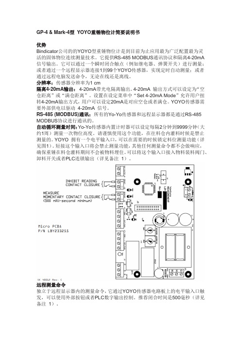
YOYO 拥有一个电平输入口,可以在需要的时候锁定料位测量功能(详见图1)。
短接这个输入口将会禁止测量功能,其他任何测量命令都不会做响应,确保重锤在料仓灌料期间不会被物料埋住。
可以将这个输入口接入物料装料阀门、卸料开关或者PLC连锁输出(详见备注1)。
远程测量命令独立于远程显示器内的测量命令,它通过YOYO传感器电路板上的电平输入口触发,可以使用外部按钮或者PLC数字输出控制。
推荐闭合时间是500毫秒(详见备注1)。
备注1:输入口为有源输入,内置5 VDC电压。
切勿为“inhibit”和“measure”输入口接入外部电源。
输入口使用干式触点。
远程显示:远程显示器最多可以控制99个YOYO传感器。
它拥有一个4行X20字符LCD背光显示屏。
新版料位计说明书
倡导节能环保还祖国以蓝天CLTL A型智能料位计使用说明书河南倡蓝工业炉科技有限公司目录一、产品概述 (2)二、设备结构 (2)三、技术规格 (4)四、工作原理 (4)五、功能与使用 (5)六、安装与接线 (7)七、调试步骤 (9)八、注意事项 (10)一、产品概述智能探测料位计采用了德国西门子可编程控制器、触摸屏界面及欧姆龙旋转编码器,具有运行可靠、响应速度快、测量精确、调试方便简捷、可远程控制、可用于恶劣的工业环境等优点。
工业现场的传感器与仪表往往相距几十米甚至数百米远,这就要求设备具有很强的抗干扰能力和很高的可靠性。
仪表型料位计的仪表部分采用分立电子元件和普通仪表,抗干扰能力很差。
因电磁的干扰很容易造成数据的漂移,导致测量不准确,甚至无法测量。
为此,我公司在原产品的基础上,采用了西门子可编程控制器和欧姆龙绝对型旋转编码器等先进的高科技产品,欧姆龙绝对型旋转编码器可以把重锤的位置转化成格雷码送到PLC,重锤的某一位置对应一个唯一的码值。
即使某一时刻受到干扰,但下一时刻就可以把丢失的码找回来,不会因为干扰而产生累计误差,保证了重锤回原点的准确性,从根本上解决了其抗干扰难题。
同时还增加了西门子触摸屏操作员界面。
触摸屏具有功能强、背光液晶显示、全中文界面、操作简捷、维护方便等特点。
友好的操作界面使得CLTL-A型料位计调试简捷、操作简便、数据直观。
特别适用于冶金、煤炭、化工、水泥、储运等行业的竖炉和料仓的粉末状、块状、颗粒状物料的料位检测与控制。
二、产品构成本产品由控制箱、驱动机箱及连接电缆组成。
控制箱可安装在现场的墙壁上或支架上(也可以安装在控制室内),通过连接电缆与驱动机箱相连接共同组成料位计探测系统 (见图1) 。
图1 系统结构图控制箱由西门子SMARAT-200可编程控制器、模拟量输入模块(EM AQ02)、操作员HMI触摸屏、断路器、接触器等组成。
驱动机箱由电器底板、减速电机、绕线盘、绝对型旋转编码器、摆动支架、万向开关、导向轮、重锤等零部件组成(见图2)。
- 1、下载文档前请自行甄别文档内容的完整性,平台不提供额外的编辑、内容补充、找答案等附加服务。
- 2、"仅部分预览"的文档,不可在线预览部分如存在完整性等问题,可反馈申请退款(可完整预览的文档不适用该条件!)。
- 3、如文档侵犯您的权益,请联系客服反馈,我们会尽快为您处理(人工客服工作时间:9:00-18:30)。
LHY280400 Rev. CI N S T A L L A T I O N , O P E R A T I O N &M A I N T E N A N C E M A N U A LMark-4 Yo-Yo®Inventory Management System1.0 PRODUCT DESCRIPTION1.1 FunctionThe Bindicator general purpose Mark-4 Yo-Yo®is a sensor that is mounted to the top of a vessel and measures the distance to the product in the tank. This is done by lowering a weight to the surface of the product, while measuring the amount of cable used. When the weight contacts the material, the unit senses the loss of weight. The motor reverses and automatically returns the weight to its home position, sealing the weight against a bellows assembly in the bottom of the sensor housing. The cable is measured while traveling in both directions and the readings are compared. If each of these measured distances do not agree, the sensor automatically takes another measurement.A microprocessor located on board has the ability to convert this measured distance to "level of product" or "volume/weight of product" in the vessel. This value is communicated via RS-485 MODBUS to the Remote Display, or transmitted via 4-20mA to other equipment.1.2 ApplicationsBindicator Mark-4 Yo-Yo®sensors provide level measurement in most dry bulk solid materials, liquid/solid interfaces, and liquids at atmospheric pressure. They can be used for measurement of materials with temperatures of up to 200o F (93o C). Consult Bindicator Applications Department if you are using the Mark-4 Yo-Yo®sensor in material temperatures above 200o F (93o C).Locating the proper mounting location on the top of your tank is important. When filling bulk materials into a vessel, a positive angle of repose (mound up) is created. When emptying, the angle of repose may go negative. In a round, center fill and discharge vessel, the point that best averages this angle of repose is located at 1/6 the diameter of the tank (or 1/3 radius) from the outside wall.The Mark-4 Yo-Yo®sensor, like any other plumb bob device, drops a weight into the vessel. If the material in the vessel buries this weight, the sensor will become inoperative. Therefore, it is not recommended that readings be taken when there is a chance the weight will be buried. This could occur when the vessel is being filled or discharged.If material is sticky and will eventually build up on the weight, this will cause the weight to become stuck at its home position inside the standpipe. In order to avoid this, a tare stop is available. The tare stop will still seal against the bellows when in the "home" position, but the weight is left suspended below the standpipe. If build-up does occur on the weight, it will not become stuck because it never enters the standpipe.Consideration should be given to airflow characteristics in the vessel when there is no product movement. The internal dynamics of bulk solids storage vessels can vary drastically. If your vessel includes air movement equipment that continuously filters or moves air, this could cause problems with the weight when it is dropped into the vessel. Air currents can cause the weight to swing or spin as it is being lowered or raised inside the vessel. If the weight spins, it can create knots in the cable. Knots in the cable could hinder the movement of the weight as it is being retracted, or on the next measurement, when it is lowered. A swinging weight can be the cause of inaccurate readings or can abrade and eventually cut the cable as a result of rubbing on the edge of the standpipe at the top of the vessel.1.3 FeaturesThe Mark-4 Yo-Yo®is Bindicator's most application and interconnection flexible sensor to date. This sensor provides both RS-485 MODBUS communications and an isolated, reversible 4-20mA output. It can be cycled using a momentary contact closure such as a spring-loaded push button; or from the remote display by selecting 1 of up to 99 sensors and requesting a measurement; or by requesting the measurement via computer, either on-site or off-site.Resolution:Resolution of the sensor is 1 cm (0.39 in).Isolated 4-20mA Output:The 4-20mA output is optically isolated, and reversible. Setting "Tank Empty Distance" and "Tank Full Distance" values sets the parameters for the 4-20mA output. Selecting the "Set 4-20mA Mode" in the Program Menu allows the user to reverse the 4-20mA signal. The user is asked to choose whether 20mA represents a full tank or an empty tank. An external power supply is required to drive the 4-20mA signal.RS-485 (MODBUS) Communications:All Mark-4 Yo-Yo®sensors and the Remote Display are connected to the network via RS-485 MODBUS protocol.Automatic Cycle Timer:The Mark-4 Yo-Yo®sensor also has an on-board timer that can be set to take automatic readings from once every 2 minutes to 9999 minutes (approximately 1 week). Please use caution when using this feature. Sending the sensing weight to the material surface should not be done while the vessel is filling. For this reason, the sensor is also equipped with connections for an external switch that can be used to inhibit the initiation of a measurement (see Figure 1). Shorting these terminals inhibits the sensor from taking a reading, regardless of how the reading is requested. Examples of ways to ensure the weight does not get buried by material filling the vessel include connecting these pins to a limit switch on a diverter valve that swings fill into a vessel, truck loading switch, or PLC digital output (see Note 1).Remote Measurement RequestSeparate from the sensor measurement request from the display, are terminals on the Mark-4 Yo-Yo®sensor board that allows connection of a spring loaded push button, or a PLC digital output to request a reading of each sensor (see Figure 1). This is a momentary contact closure. Recommended "start pulse" is 500 milliseconds (see Note 1). Note 1: Voltage across these terminals, supplied from the sensor board, is 5 VDC. Do not provide external power to the “inhibit” and “measure" terminals. Provide a dry contact only.Micro PCBAP/N LBY233255SK 40012 Rev. CFigure 1. Inhibit and Measure Contact ClosuresRemote Display:The Remote Display is capable of monitoring up to 99 sensors. It has a 4-line x 20-character LCD backlit display. The Remote Display is connected to the sensors via the RS-485 MODBUS network. All sensor programming and measurement requests are performed using the display. However, set-up and configuration settings are stored in each sensor.The display does not require separate power unless equipped with a heater. Only when the display will be subjected to temperatures lower than -4o F (-20o C) is a heater required. The heater requires 120 VAC or 240 VAC depending on the specified display model.Optional Telephone Modem:If remote site monitoring is required, a telephone modem is available. The modem connects directly to the RS-485 MODBUS network and can be installed in the Remote Display. A direct dial, analog telephone line is required.1.4 Model Code IdentificationMark-4 Yo-Yo®SensorRemote DisplayNote 1:Specify monofilament cableNote 2:Maximum length 50 ft (15.24 m)Note 3:For operation below 32o F (0o C)Note 4:For operation below -4o F (-20o C)Note 5:Maximum one modem allowed per system1.5 Technical Specifications1.6 DimensionsFigure 2. Mark-4 Yo-Yo®Sensor Dimensions in (mm)Figure 3. Remote Display Dimensions in (mm)9Installation, Operation & Maintenance Manual LHY280400BINDICATOR5.2 Set-up / ProgrammingThe Mark-4 Yo-Yo®sensors and remote display communicate vis RS-485 MODBUS protocol. Each sensor has a couple of rotary switches located near the center of the electronics board. Sensors are addressed using these switches. All sensors are shipped from the factory with address #01. If you have purchased more than one sensor, or are adding to an existing systems, the sensors will need to be individually addresses. Each sensor MUST have a unique address between 1 and 99 inclusive. Once address switches have been set, sensor must bere-initialized by pressing the reset button on board or by turning off and back on the power sensor. See Figure #6.When the Mark-4 Yo-Yo®sensor is installed on the tank top, properly addressed, and connected, it will begin communicating with the display. The display automatically looks for sensor address #01 or the first enabled sensor. From this address the user can enable all other sensor addresses using the "Programming Mode". The access code for this menu is "1936". Use the "up", "down" and "right" arrows to program each sensor. Pressing "ENTER" stores a change in the readout. When all changes are complete for a given sensor, go to "SAVE & QUIT" and press "ENTER". This sends all changes from the display to the sensor.Note:While in the Programming Mode, no information is transferred between the Remote Display and other Mark-4 Yo-Yo®sensors. For this reason, there is an automatic timeout period. If no keys are pressed for one (1)minute, the Remote Display will exit the Programming Mode without saving changes and return to theOperating Mode.BINDICATOR Installation, Operation & Maintenance Manual LHY2804001011Installation, Operation & Maintenance Manual LHY280400BINDICATOR 25.3 Programming ModeThe Programming Mode allows the user to configure a single sensor or multiple sensors. To enter the menu system a 4-digit numerical password is required. This password is "1936". The system does not allow changes to the password at this time.While in this mode the display will indicate which sensor address is currently being edited. To select a menu item use the arrow keys to place the * beside the desired selection and press "ENTER". To move back, press "ESC". A Settings and Parameters Log is located on page 24 of this manual for recording your Mark-4 Yo-Yo ®sensor settings.Note:While in the Programming Mode, no information is transferred between the Remote Display and other Mark-4Yo-Yo ®sensors. For this reason, there is an automatic timeout period. If no keys are pressed for one (1) minute, the Remote Display will exit the Programming Mode without saving changes, and return to the Operating Mode. If programming is interrupted before completion, “Save and Quit” to avoid losing your settings.Following, is a description of each menu item in the Programming Mode:UnitsDetermines if the sensor will display linear distance units in feet or meters, or engineering (volume/weight) units. If English engineering units are selected on this menu, all tank definition distances will be edited using "feet". If metric engineering units are selected, all distances will be edited using “meters”.When Engineering Units are selected in conjunction with a cone height greater than "0", the displayed value and the 4-20mA output are linearized. This linearization assumes a center discharge cone below a round, straight sidewall silo.Note:When selecting any engineering unit, the "full scale value" (amount of material that corresponds to the "tankfull distance” must also be specified. See "full scale value" in Tank Parameters on page 12.Distance Units Feet (Default - One decimal place)Meters (Two decimal places)Engineering Units (no decimal places)Cubic FeetCubic MetersLbsKgsGallonsLitersTank ParametersThis menu defines the tank dimensions (see Figure 7). All distances except "cone height" are taken from the sensor's "Home" position. The firmware allows the user to enter only the following possibilities:Tank Height >= Maximum Move Distance >= Tank Empty DistanceTank Empty Distance > Tank Full Distance >=0Tank Height > Cone Height >= 0Maximum Move Distance >= (Tank Height )Tank Height:This parameter is the distance from the Yo-Yo ®sensor’s home position to the bottom of the tank. The default value is 75 ft (22.86 m) and the range is from 3.3 ft to 199.9 ft (1 m to 60.93 m).Note: Standard cable length is 100 ft (30.48 m).Do not program a value greater than this length unless a specialstorage wheel with an extended length of cable has been provided with the sensor.The tank height value must be greater than or equal to “maximum move distance” and “tank empty distance.”Therefore, setting this value to less than 75 ft (22.86 m) will automatically reduce the value of the “tank empty distance” and “maximum move distance” to the same value.BINDICATOR Installation, Operation & Maintenance Manual LHY28040012Tank Full Distance:This parameter is the distance from the Yo-Yo ®sensor’s home position to the level of material where the tank is considered full. This parameter also determines the 20mA output point when 20mA represents a “full” vessel. If 20mA represents an empty vessel, the “tank full distance” is also setting the 4mA point. The default value for “tank full distance” is 0, and the range is from 0 ft to 1999.9 ft (0 m to 60.93 m). Also, see “4-20mA mode” on page 13.Tank Empty Distance:This parameter is the distance from the Yo-Yo ®sensor's home position to the point where the tank is considered empty. This parameter normally determines the 4mA output. The default value is: 75 ft (22.86 m) (same as "tank height") and the range is from ½ of the tank height parameter to 199.9 ft (60.93 m).Maximum Move Distance:This parameter is the maximum travel distance from the Yo-Yo ®sensor’s home position. This parameter is used to limit the sensor from traveling through the discharge of the tank, or into discharge equipment such as screwconveyors. When the Yo-Yo sensor reaches this travel distance, it will stop the measurement, retract the weight, and display ‘MAXMOVE DIST REACHED’. It will also display the distance traveled. The default value of this parameter is 75 ft (22.86 m) and the range is from “tank empty distance” to 199.9 ft (60.93 m). The “maximum move distance”value must be less than or equal to the "tank height" value.Cone Height:This parameter is only used when "engineering units" have been selected and is used to calculate the volume of material in the cone of a center fill, center discharge, round vessel. It is the distance from the bottom of the tank to the top of the cone. The default value is 0 ft (0 m) and the range is from 0 ft to 199.9 ft (0 m to 60.93 m).Full Scale Value:This entry is shown only if “engineering units” have been selected. It is the maximum (full) tank weight or volume capacity of the tank from the bottom of the tank to the level where the tank is considered full (see “tank full distance”in Figure 7). The default value is 1 and the range is from 1 to 9,999,999.Display ModeMaterial Mode:If feet or meters have been selected in the "Units" menu, the display shows the level of material in the tank. This is the distance from the bottom of the tank to the top of the material. When engineering units are selected, the display shows the weight or volume of material in the vessel. When using the 4-20mA output, the range is defined as the points between “tank empty distance” and “tank full distance”. Material mode is the default setting.Mathematically: Level Material Mode = Tank Height - Measured Level (see Figure 8)Tank Parameters (continued)13Installation, Operation & Maintenance Manual LHY280400BINDICATOR 4-20mA ModeThis parameter is selected independent of the air and material modes. Typically, when the display is programmed for material mode, 20mA will also represent a full tank. Inversely, when displaying in air mode, 20mA will be set to rep-resent an empty tank. However, both functions can be independently reversed if desired.Note: If engineering units have been selected and a cone height greater than "0" specified, the 4-20mA output will be linearized for the cone section (see “Units” on page 11).If power has been lost and restored, or on initial power-up, the 4-20mA output will indicate greater than or equal to a full tank. The actual output could be greater than or equal to 20mA or less than or equal to 4mA depending on the selected mode. When a new reading is requested and the cycle is completed within the set tank parameters, a new value, typically between 4 and 20mA, will be produced. Once updated, the Mark-4 Yo-Yo ®sensor will hold the 4-20mA value until cycled again.20mA = Full (Default)20mA = EmptyAutotimer ModeWhen the autotimer mode is set to ON, the Mark-4 Yo-Yo ®sensor is able to take a reading automatically at an inter-val defined in menu "Autotimer Time". When the autotimer mode is set OFF, the Mark-4 Yo-Yo ®sensor will onlybegin a measurement when manually requested. We strongly recommend the use of the "inhibit" feature when using the autotimer mode. See “Automatic Cycle Timer” on page 2 for a more detailed description of this inhibit feature.OnOff (Default)Autotimer TimeThis entry is shown only if autotimer mode is set to ON. This parameter selects the amount of time betweenautomatic cycle requests. The default setting is 1440 minutes (24 hours). Select a value 2 minutes to 9999 minutes (approximately 1 week).Note:The motor has a 50% duty cycle. Do not run the Mark-4 Yo-Yo ®sensor continuously.Air Mode:If feet or meters have been selected in the "Units" menu, the display will show the distance to the material minus the “tank full distance” value (see Figure 8). For example, if the material in the tank is 10 ft from the sensor's home posi-tion and the tank full distance is "0", the display will show 10 ft. In the same scenario, with the “tank fulldistance” set to 3 ft, the display will now show 8 ft.The same rules apply when using engineering or distance units; when volumetric or mass units have been selected,the display will indicate the volume or weight available (outage) in the vessel from the Tank Full Distance point. Only the unit of measurement changes.BINDICATOR Installation, Operation & Maintenance Manual LHY2804001415Installation, Operation & Maintenance Manual LHY280400BINDICATORBINDICATOR Installation, Operation & Maintenance Manual LHY28040016C17Installation, Operation & Maintenance Manual LHY280400BINDICATORInstallation, Operation & Maintenance Manual LBY280183BINDICATOR150 Venture BoulevardSpartanburg, SC 29306Phone: (864) 574-8060, Fax: (864) 574-8063Customer Care: (800) 778-9242Internet: email: sales@© 2006 All rights reserved.All data subject to change without notice.LHY280400 Rev. C 6/06。