
Gambit-2.2-lect-01a-intro
Introductory GAMBIT Training GAMBIT 2.2 February 2005
GAMBIT Agenda (Day 1)
8:00-9:30 9:30-10:00 10:00-11:00 11:00-12:00 12:00-1:00 1:00-2:00 2:00-2:45 2:45-3:45 3:45-4:30 4:30-5:00 Introduction to GAMBIT + Demo Tutorial: Creating and Meshing a Basic Geometry Creating Geometry in GAMBIT Exercise 1: Geometry Creation Lunch Edge and Face Meshing Exercise 2: 2D Geometry and Mesh Generation Volume Meshing Exercise 3: 3D Geometry and Mesh Generation Volume Decomposition Examples
Three files are created inside this directory
ident.dbs jou trn = the database. All information will be saved in this file. This file is NOT retrievable upon a crash = the journal file. This file is directly accessible from the Run journal form = the transcript file. Output from GAMBIT
Select working directory Type in Session ID or select from previous stored sessions. Startup Options
GAMBIT can be also started up from a DOS command prompt or LINUX/UNIX prompt by typing in “gambit Session Id”.
Create full geometry Decompose into mesh-able sections
Meshing
Local meshing: Edge, Boundary layers and Size Functions Global meshing: Face and/or Volume
The directory GAMBIT.# is removed The lock-file ident.lok is deleted
1-8
© Fluent Inc. 5/11/2011
Fluent User Services Center
Introductory GAMBIT Training GAMBIT 2.2 February 2005
Cleanup and modification of imported data
Mesh generation for all Fluent solvers (including FIDAP and POLYFLOW)
Structured and Unstructured hexahedral, tetrahedral, pyramid, and prisms.
1-2
© Fluent Inc. 5/11/2011
Fluent User Services Center
Introductory GAMBIT Training GAMBIT 2.2 February 2005
GAMBIT Agenda (Day 2)
8:00-9:00 9:00-10:00 10:00-11:00 11:00-12:00 12:00-1:00 1:00-2:00 2:00-3:00 3:00-3:30 3:30-5:00 Mesh Control Through SF’s and BL’s Exercise 4: Mesh Control through SF’s and BL’s CAD/CAE Data Exchange and Geometry Cleanup Tutorial: Virtual Cleanup (Tutorial 5 – Sedan
Batch mode (Run)
All commands processed without interruption. "read pause" command will force interrupt with resume option appearing.
# = the process number It also creates a "lock" file, ident.lok, in the working directory ident.lok prevents any user from starting up another session using the same identifier in the same directory. If the code crashes, this file needs to be manually removed.
Introductory GAMBIT Training GAMBIT 2.2 February 2005
GAMBIT Start-up
GAMBIT can be started up using the startup icon (Windows XP/2000 only).
Gambit 2.2.30
Exercise 5: Volume Decomposition Exercise 6: Flow Probe or GAMBIT to FLUENT Tutorials (2D Asymmetric Diffuser or 2D Turbine Cascade)
1-3 © Fluent Inc. 5/11/2011
1-6
© Fluent Inc. 5/11/2011
Fluent User Services Center
Introductory GAMBIT Training GAMBIT 2.2 February 2005
Files (1)
GAMBIT directory and files When GAMBIT starts up, it creates a directory called GAMBIT.#
Mesh examination Zone assignment
Continuum and Boundary attachment
Mesh export
1-5
© Fluent Inc. 5/11/2011
Fluent User Services Center
1-9
© Fluent Inc. 5/11/2011
ቤተ መጻሕፍቲ ባይዱ
Fluent User Services Center
Introductory GAMBIT Training GAMBIT 2.2 February 2005
Running Journal Files
Journal files can be processed in two ways:
Operation
General sequence of operations
Initial setup
Solver selection, Mesh size, Defaults, etc.
Geometry Creation (ACIS, STEP, CATIA, Parasolid, IGES or Mesh import)
Mesh quality examination Boundary zone assignment
1-4
© Fluent Inc. 5/11/2011
Fluent User Services Center
Introductory GAMBIT Training GAMBIT 2.2 February 2005
Fluent User Services Center
Introductory GAMBIT Training GAMBIT 2.2 February 2005
Introduction to GAMBIT
1-1
© Fluent Inc. 5/11/2011
Fluent User Services Center
Journal Files
Journal File:
Executable list of Gambit commands
Created automatically by Gambit from GUI and TUI. Can be edited or created externally with text editor.
Upon Save, earlier versions of ident.dbs and ident.trn will be overwritten, while new commands are appended to the file ident.jou
Upon successful exit of GAMBIT:
Geometry – Virtual Cleanup)
Lunch Geometry Cleanup Tools + Demo Tutorial: Geometry Cleanup (Tutorial 13 – Catalytic
Converter or Tutorial 14 – Airplane Geometry)
Gambit教程

旋转
轴和旋转的方向根据 右手规则来决定
起始边
面创建– 扫描边
扫描边(有或无网格)
Rigid方式 –边在整个扫描过程中保持一定 垂直方式 –边在绕轴旋转的过程中保持与轴垂直
草绘和扭曲选项
路径
边
垂直, 草绘 = 0
严格的
垂直, 草绘 = 0, ± 30
垂直, 扭曲 = 120
面创建 – 其它工具
理解连通性的概念非常重要. 为了使流体能够从一个面/体流到另一个面/体,这两个实体必须连接在一起 正投影网格 –两个实体的连接边界上的节点是共享的
正投影接触面 (面相连接)
非正投影接触面
(面不相连接)
通用操作 – 连接
连接
点,边和面都可连接. 这个操作删除所有重复实体并重新连接上面的实体. 只有不超过ACIS标准公差的实体才会被连接. 存在的网格将会被保存起来
窗体
浏览框 (选择) 控件 (黄) I未激活 (白)
选择按钮
(互不相容)
选择按钮
(激活菜单)
文本框
(单击 激活/编辑)
检查框
(非互不相容)
命令按钮
窗体
文本框
数据, 公式, 参数 窗体有几个文本框 输入的 顺序不重要 用Tab键来指向下一个文本框 鼠标左键单击激活任何对话框 激活的列表框显示黄色 鼠标左键单击激活 显示最近被选中块的名字 被选中的块同时增加亮度,在屏幕上显示为红色 所有先前被选中过的块显示粉色
鼠标操作
操作 左键 中键 右键
拖动 Shift + 单击 双击 Ctrl + 单击
x/y 轴旋转 选择
Gambit使用教程及入门实例33页
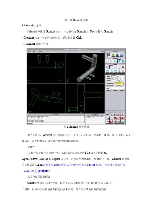
第一章Gambit使用1.1 Gambit 介绍网格的划分使用Gambit软件,首先要启动Gambit,在Dos下输入Gambit<filemane>,文件名如果已经存在,要加上参数-OkL一.Gambit的操作界面图1 Gambit操作界面如图1所示,Gambit用户界面可分为7个部分,分别为:菜单栏、视图、命令面板、命令显示窗、命令解释窗、命令输入窗和视图控制面板。
文件栏文件栏位于操作界面的上方,其最常用的功能就是File命令下的New、Open >Save>Save as和Export等命令。
这些命令的使用和一般的软件一样。
Gambit 可识别的文件后缀为.dbs,而要将Gambit中建立的网格模型调入Fluent使用,则需要将其输出为・msh文件(f∏e∕export)°视图和视图控制面板Gambit中可显示四个视图,以便于建立三维模型。
同时我们也可以只显示一个视图。
视图的坐标轴由视图控制面板来决定。
图2显示的是视图控制面板。
图2视图控制面板视图控制面板中的命令可分为两个部分,上面的一排四个图标表示的是四个视图,当激活视图图标时,视图控制面板中下方十个命令才会作用于该视图。
视图控制面板中常用的命令有:画全图显示、典!选择显示视图、星!选择视图坐标、鱼1选择显Hl示项目、上ΞJi宣染方式。
同时,我们还可以使用鼠标来控制视图中的模型显示。
其中按住左键拖曳鼠标可以旋转视图,按住中键拖动鼠标则可以在视图中移动物体,按住右键上下拖动鼠标可以缩放视图中的物体。
命令面板命令面板是Gambit的核心部分,通过命令面板上的命令图标,我们可以完成绝大部分网格划分的工作。
图3显示的就是Gambit的命令面板。
weism图3 Gambit的命令面板从命令面板中我们就可以看出,网格划分的工作可分为三个步骤:一是建立模型,二是划分网格,三是定义边界。
这三个部分分别对应着OPeration区域中的前三个命令按钮Geometry(几何体)、mesh (网格)和ZoneS (区域)。
便携式伽玛谱仪需求附件
便携式伽玛谱仪需求附件一、设备名称:便携式伽玛谱仪二、参考规格型号:美国堪培拉公司的INSPECTOR1000三、数量:1套四、实现功能:1、4种工作方式,可满足常规γ测量需要,剂量率测量,包括总的和每个核素产生的剂量率,放射源寻找,实时γ核素识别,包括所有的或感兴趣的γ核素,采用独有的无源效率刻度实现现场活度定量测量,可对每种核素的剂量率和活度设置报警阈值(2个),连续实时测量核素能谱,并分析每个核素的剂量率贡献,更新剂量率显示2、采用CANBERRA久经验证的谱分析算法和功能3、通过USB可与计算机及Genie2000软件配套使用4、通过CE认证,满足相关电磁兼容性和安全标准5、采用数字信号处理技术(DSP)多道分析器和稳谱技术,具有极高的信号通过率、稳定性、准确性、一致性和可重复性6、10cm2彩色LCD大触摸屏,多种显示方式,界面友好直观,操作简便,无需很多培训7、声音和显示报警提示8、特殊外壳、按键和显示屏设计,可以去污五、技术参数1、剂量(率)范围:10nSv/h-100mSv/h,10nSv-10Sv2、能量范围:LaBr3:30keV-3MeV, GM:30keV-1.4MeV3、电池:锂离子可充电电池,12h4、质量:1.8kg,包括NaI(3''×3'')探头和电池5、外形尺寸:22×18×7cm6、温度:-10 - +50℃。
湿度:80%7、防护:IP548、选用LaBr3探头:1.5''x1.5''9、谱分析:9.1、计数通过率:>50kcps9.2、输入计数率:>500kcps9.3、时间设置:1s-1000000s,实时和获取活时间9.4、道数:最大4096道10、核素库:核材料、工业、医用同位素;32个可自定义核素库(每个可含50多个核素)11、存储量:可存储不少于250个2048道的独立谱和设置参数12、每个谱可设置64个感兴趣区13、全自动谱采集和处理六、设备配置要求1、便携式伽玛谱仪,2、电缆、充电器,3、1个便携箱包。
gambit

生成一个虚面如果用户指定生成一个虚面,用户也可以指定一个寄主面或者体积。
∙如果用户不指定寄主面或者体积,GAMBIT将生成一个孤立的面——该面的形状仅仅由它的边界确定。
∙如果用户指定了一个寄主面或者体积,GAMBIT将生成一个寄生面并且用寄主实体现有的几何结构(形状)来确定该虚面的形状。
指定误差值如果用户为生成的虚面指定了一个寄主面,GAMBIT允许用户指定一个误差值。
该误差值作为线框边与寄主面表面之间距离的最大允许值。
使用Create Face From Wireframe窗口要打开Create Face From Wireframe窗口(如下图),点击Geometry/Face子工具框中的Create Face From Wireframe命令按钮即可。
分割体积page212Split V olume命令允许用户将一个现有的体积分割成一个或者两个实际的或者虚拟的体积。
要通过命令分割一个体积,用户必须设定以下参数:•要分割的体积•分各类型•分割工具•分割选项设定被分割的体积GAMBIT允许用户风格实际的或者虚拟的体积,但是对于通过分割生成的体积的类型有以下限制:•如果用户分割一个实际的体积,用户可以生成实际的体积或者虚拟的体积•如果用户分割一个非实际的体积,用户必须生成虚拟的体积设定分割类型共有三种分割类型选项:•Real connected•Real disconnected•Virtual connectedReal connected选项生成通过一个或者多个实面相连的实际的体积。
Real disconnected选项生成不相连的体积。
Virtual connected选项通过分割操作生成虚拟的体积,并且这些体积通过一个或者多个公共虚面相连。
设定分割工具要分割一个体积,用户必须设定分割工具——也就是说确定用于分割的现有几何结构。
分割类型如下确定了有效的分割工具:•对于Real connected或者Real disconnected分割操作,分割工具必须高喊一个实面或者一个实际的体积。
Gambit及Fluent操作步骤图解

Gambit及Fluent操作步骤图解现在PRO/E软件中建立燃烧室和气缸工作容积的三维图,并且以*.stp格式输出,在磁盘建立一个文件夹(比如在D盘建立一个名称为step的文件夹),将刚才的*.stp文件放在此文件夹下面。
桌面上打开Gambit图标,见图1。
图1在菜单File下,点击Import > STEP,见图2。
打开Import STEP File窗口,见图3。
图2图3 找到并打开刚才的*.stp文件,如图4所示。
图4 使用2条边建立一个面,见图5。
图5可以将本模型划分为两部分,打开Split Volume窗口,使用刚才建立的面将模型划分为2个部分,见图6。
图6, 进行网格划分,先对上面的体积进行网格划分,由于其形状比较规则,所以可以使用6面体网格单元,见图7。
然后对下面的体积进行网格划分,由于其形状不规则,所以选用4面体网格单元,见图8。
全部网格划分完后,见图9。
图7图8图9点击右下方的SPECIFY MODEL DISPLAY ATTRIBUTES,在其面板上的Mesh选项后点击off,即可关闭网格显示,但是此时模型网格已经划分了。
图10边界条件的设置,分别选中需要设置的面,如本例中选中face4,将其名称设为movwall,类型设为wall,见图11. 选中face12,将其名称设为middle,类型设为INTERIOR,见图12. 选择face2和face3,将其名称设为cylinder,类型设为wall。
图11图12图13指定体,分别设置模型的上部和下部为V2和V1,如图14和15.图14图15以上模型网格设置好之后,将模型以*.msh格式输出,本例子以cylinder.msh 输出,见图16。
图16打开FLUENT图标,在FLUENT Versions窗口中选择3d,见图17。
图17分别选择File>Read>Case,找到前面输出的cylinder.msh文件,选择并打开,见图18。
Multi-Port Valve User Manual

RMULTI-PORT VALVE USER MANUALFor CMP# 27505-200-000; 27507-200-000PRODUCT INFORMATIONThese multi-port valves are replacements of Pentair 261055 or 261152 Valves. The filter valve features an easy-to-use lever action handle that lets you dial up to six valve/filter functions- filter, backwash, waste, rinse, closed, and recirculate. The valve has 2in FPT and bulkhead fittings of 7-1/2” centerline distance.FILTERPUMP►SAND TOP/DE BOTTOM►THROUGH FILTER►SAND BOTTOM/DE TOP►POOL RETURNFor normal filter action and vacuuming pool through filter.BACKWASHPUMP►SAND BOTTOM/DE TOP►THROUGH FILTER►SAND TOP/DE BOTTOM►WASTE For cleaning filter by reversing flow.RINSEPUMP►SAND BOTTOM/DE TOP►THROUGH FILTER►SAND BOTTOM/DE TOP►WASTEFor start-up cleaning and resetting filter bed after backwashing.WASTE PUMP►WASTEFor vacuuming directly to waste, lowering pool level or draining pool.CLOSED NO FLOW. DO NOT USE WHEN PUMP IS IN OPERATION For shutting off all flow to filter and pool.RECIRCULATEPUMP►POOL RETURNFor circulating water without going through filter.Valve Setting Water Flow Path; Setting Function27505-200-000Replacement for Pentair 261055. It works with Pentair Triton sandfilters.27507-200-000Replacement for Pentair261152. It works with Pentair Quad, FNS plus and Nautilus plus NSP D.E. filters.*Pentair is a registered trademark of Pentair Aquatic SystemsINSTALLATION & SERVICE INSTRUCTIONS• Confirm correct valve is being used for your filter type and model.• To install valve to filter, secure bulkhead nuts on valve to fittings on filter. TIGHTEN THE NUTS BY HAND ONLY. Connect pump, return, and waste lines by following the markings of the ports.• VALVE TOP IS UNDER SPRING LOAD. To open top half and service valve, evenly and alternately loosen cover screws.• To re-assemble the top half, place diverter on a smooth and firm surface. Assemble parts on shaft byfollowing Figure A. Make sure the pointer on handle and the arrow on diverter point to same direction. Press down the cover by depressing heavy-duty spring and secure handle with dowel pin.• To re-assemble the top half to valve bottom, ensure bottom gasket and diverter sealing surface areclean and free from nicks to insure positive sealing. Tighten cover screws evenly and alternately. DO NOT OVERTIGHTEN THE SCREWS.• WINTERIZATION: To winterize, drain the pump and filter per manufacturer’s instructions. Press and turn valve handle to a position that is between any two settings.1Handle 12Dowel Pin13Plastic Washer 14Top Cover15Top Cover O-ring 16Spring Washer 17Heavy Duty Spring 18Diverter O-ring 29Diverter 1Item QTY Item Description Figure A: Top Half Assy Components0313 sbFor the full list of replacement parts of this unit, please check our catalog or our website at .CUSTOM MOLDED PRODUCTS, INC | 800-733-9060 | NEWNAN, GEORGIA 30265 | Complete Top Half Assy 27507-200-100(includes 1-9)。
gambit
一.边界层边界层是指定与边或者面相邻区域的网格接点的距离,目的是控制网格密度,从而控制感兴趣区域计算模型的有用的信息量。
例如:在一个液体流管中,我们知道靠近壁面处的速度剃度大,而中心处的速度剃度小,为了使得壁面处的网格密而中心处的网格稀疏,我们就在壁面处加一边界层。
这样我们就能控制网个密度。
要定义一个边界层,你要定义以下参数:1)边界曾依附的边或者面2)指定边界层方向的面或者体3)第一列网格的高度4)相邻列之间的比例因子5)总列数,指定了边界层的深度同时,你也可以指定一个过度边界层。
要指定一个过度边界层,你需要定义以下参数(过度模式,过度的列数)1)生成边界层需要定义以下参数:i)size:包括指定第一列的高度和相邻列的比例因子ii)internal continuity :当在体的某个面上施加边界层时,gambit会把边界层印在与这个面相邻的所有面上,如果在体的两个或者更多的面上施加边界层,那么边界层就有可能重叠,internal continuity 这个参数就决定了边界层如何重叠当选择internal continuity 时,gambit不会在相邻的面上互相施加边界层否则就会在相邻的面上互相施加边界层具体可以看guide的图示:同时这个参数还影响施加了边界层的体可以采用何种方式划分网格corner shape :gambit 允许你控制conner(即边界层依附的的两条边的连接点处)附近区域网格的形状iii)Transition Characteristics需要定义以下两个参数:Transition pattern指的是边界层远离依附边或者面那一侧的节点的排布情况Number of transition rows这个列数肯定要小于前面指定的那个列数。
iv)Attachment Entity and Direction指定方向非常重要,可以通过鼠标和list 对话框来完成。
二)边划分网格1)mesh edges(在边上生成节点)你可以在一个模型的任何一条边上或者所有边上生成网格节点或者对其进行划分而不生成网格节点。
Gambit 操作基础教程
GAMBIT 用户向导的第四章详细描述了菜单条款,包括在每个相关菜单上可用的命令。 0.5.3 操作工具板
操作工具板在 GUI 的右上角。它由一系列命令按钮组成,每个按钮在创建和网格模型过 程中起到特定的功能。
-2 中的表格,他允许你对模型和网格操做设定参数,边界属性的分配和 GAMBIT 坐标系和
格子的创建和处理。
图 0-2:GAMBIT 指定表格的例子 当你打开一个特定表格,它在表格域中显示出来。表格域在 GUI 的右边,在操作工具板 的下方。 文本框允许你输入字符数据值。它们在表格中显示为白色的,内镶的长方形(如图 0-2 中的 Width 文本框)。每个文本框的标题在它的左边,要在文本框中输入数据,左击方框激 活它,然后从键盘上输入数据。 0.5.5 总体控制工具板 总体控制工具板在 GUI 的右下角。它的目的是让你对显示在特殊象限中的模型控制其版 面设计和图形窗口的操作和模型的外观。 0.5.6 描述窗口 描述窗口在 GUI 的底部,在总体控制工具板的左边。它的目的是显示 GUI 的组成包括 窗框、域、窗口和控制按钮。 在描述窗口上显示的信息是与当前指针所在的位置对应的 GUI 的部分。当你移动鼠标越 过屏幕,GAMBIT 更新描述窗口来改变指针所在位置。 0.5.7 抄本窗口和命令文本框 抄本窗口在 GUI 的左下方,命令文本框在抄本窗口的正下方。 抄本窗口的目的是显示命令执行的日志和 GAMBIT 在当前模型设定的信息显示。命令 文本框允许你通过直接键盘输入而不是在 GUI 上通过鼠标操作实行 GAMBIT 模型化和网格 操作。要获得更详细帮助看 GAMBIT 命令参考向导。
GAMIT使用手册
GAMIT/GLOBK软件使用手册一软解介绍GAMIT软件最初由美国麻省理工学院研制, 后与美国SCRIPPS海洋研究所共同开发改进。
该软件是世界上最优秀的GSP定位和定轨软件之一, 采用精密星历和高精度起算点时, 其解算长基线的相对精度能达到10-9量级, 解算短基线的精度能优于1mm, 特点是运算速度快、版木更新周期短以及在精度许可范围内自动化处理程度高等, 因此应用相当广泛。
GAMIT软件由许多不同功能的模块组成, 这些模块可以独立地运行。
按其功能可分成两个部分: 数据准备和数据处理。
此外, 该软件还带有功能强大的shell程序。
目前,比较著名的GPS数据处理软件主要有美国麻省理工学院(MIT)和海洋研究所(SIO)联合研制的GAMIT/GLOBK软件、瑞士伯尔尼大学研制的BERNESE软件、美国喷气推进实验室(JPL)研制的GIPSY软件等。
GAMIT/GLOBK和BERNESE软件采用相位双差数据作为基本解算数据,GIPSY软件采用非差相位数据作为基本解算数据,在精度方面,三个软件没有明显的差异,都可得到厘米级的点位坐标精度。
相比较而言,GIPSY软件为美国军方研制的软件,国内只能得到它的执行程序,在国内,它的用户并不多,BERNESE软件需要购买,它的用户稍微多一点,GAMIT/GLOBK软件接近于自由软件,在国内拥有大量用户。
GLOBK软件核心思想是卡尔曼滤波(卡尔曼滤波理论是一种对动态系统进行数据处理的有效方法, 它利用观测向量来估计随时间不断变化的状态向量),其主要目的是综合处理多元测量数据。
GLOBK的主要输人是经GAMIT处理后的h-file和近似坐标, 当然,它亦己成功地应用于综合处理其它的GPS软件(如Bernese和GIPSY)产生的数据以及其它大地测量和SLR 观测数据。
GLOBK的主要输出有测站坐标的时间序列、测站平均坐标、测站速度和多时段轨道参数,GLOBK可以有效地检验不同约束条件下的影响, 因为单时段分析使用了非常宽松的约束条件,所以在GLOBK中就可以对任一参数强化约束。
gambit 操作指南
GAMBIT 2.3Tutorial GuideMarch 2006Licensee acknowledges that use of Fluent, Inc.’s products can only provide an imprecise estimation of possible future performance and that additional testing and analysis, independent of the Licensor’s products, must be conducted before any product can be finally developed or commercially introduced. As a result, Licensee agrees that it will not rely upon the results of any usage of Fluent, Inc.’s products in determining the final design, composition, or structure of any product.© 2006 by Fluent, IncorporatedAll Rights Reserved. No part of this document may be reproduced or otherwise used in any form without express written permission from Fluent, Incorporated.Airpak, FIDAP, FLUENT, GAMBIT, Icepak, MixSim, and POLYFLOW are registered trademarks of Fluent, Inc.ImageMagick is © 1996 E.I. du Pont de Nemours and Co.All other products or name brands are trademarks of their respective holders.For GAMBIT Technical Support contact information, visit the Fluent, Inc. Web site at .Fluent, IncorporatedCenterra Resource Park10 Cavendish CourtLebanon, NH 03766iiiTABLE OF CONTENTS0. USING THIS TUTORIAL GUIDE.................................................... 0-1 0.1 What’s in This Guide .....................................................................................0-10.2 How to Use This Guide...................................................................................0-20.3 Font Conventions............................................................................................0-30.4 Using the Mouse..............................................................................................0-40.4.1 Menus and Forms .................................................................................0-40.4.2 Graphics Window.................................................................................0-40.5 GUI Components ............................................................................................0-80.5.1 Graphics Window.................................................................................0-90.5.2 Main Menu Bar ....................................................................................0-90.5.3 Operation Toolpad ...............................................................................0-90.5.4 Form Field..........................................................................................0-110.5.5 Global Control Toolpad .....................................................................0-120.5.6 Description Window ..........................................................................0-120.5.7 Transcript Window and Command Text Box ....................................0-121. CREATING AND MESHING BASIC GEOMETRY....................... 1-1 1.1 Prerequisites ....................................................................................................1-11.2 Problem Description.......................................................................................1-21.3 Strategy............................................................................................................1-31.4 Procedure.........................................................................................................1-4Step 1: Create a Brick....................................................................................1-5Step 2: Create an Elliptical Cylinder .............................................................1-8Step 3: Unite the Two Volumes ..................................................................1-10Step 4: Manipulate the Display ...................................................................1-12Step 5: Mesh the Volume ............................................................................1-14Step 6: Examine the Mesh...........................................................................1-16Step 7: Save the Session and Exit GAMBIT...............................................1-201.5 Summary .......................................................................................................1-212. MODELING A MIXING ELBOW (2-D)........................................... 2-1 2.1 Prerequisites ....................................................................................................2-12.2 Problem Description.......................................................................................2-22.3 Strategy............................................................................................................2-32.4 Procedure.........................................................................................................2-4Step 1: Select a Solver...................................................................................2-4Step 2: Create the Initial Vertices..................................................................2-5Step 3: Create Arcs for the Bend of the Mixing Elbow..............................2-10Step 4: Create Straight Edges......................................................................2-13Step 5: Create the Small Pipe for the Mixing Elbow ..................................2-15Step 6: Create Faces From Edges................................................................2-23Table of ContentsivStep 7: Specify the Node Distribution.........................................................2-26Step 8: Create Structured Meshes on Faces ................................................2-34Step 9: Set Boundary Types ........................................................................2-37Step 10: Export the Mesh and Save the Session .........................................2-412.5 Summary .......................................................................................................2-423. MODELING A THREE-PIPE INTERSECTION (3-D) ................... 3-1 3.1 Prerequisites ....................................................................................................3-13.2 Problem Description.......................................................................................3-23.3 Strategy............................................................................................................3-33.4 Procedure.........................................................................................................3-5Step 1: Select a Solver...................................................................................3-5Step 2: Create the Geometry..........................................................................3-5Step 3: Decompose the Geometry .................................................................3-9Step 4: Journal Files ....................................................................................3-19Step 5: Turn Off Automatic Smoothing of the Mesh..................................3-22Step 6: Apply Boundary Layers at Walls ....................................................3-24Step 7: Mesh the Sphere Octant Volume ....................................................3-28Step 8: Mesh the Pipe Volumes ..................................................................3-30Step 9: Examine the Quality of the Mesh....................................................3-41Step 10: Set Boundary Types ......................................................................3-443.5 Summary .......................................................................................................3-494. MODELING A COMBUSTION CHAMBER (3-D) ......................... 4-1 4.1 Prerequisites ....................................................................................................4-14.2 Problem Description.......................................................................................4-24.3 Strategy............................................................................................................4-34.4 Procedure.........................................................................................................4-6Step 1: Select a Solver...................................................................................4-6Step 2: Set the Default Interval Size for Meshing.........................................4-6Step 3: Create Two Cylinders .......................................................................4-8Step 4: Subtract the Small Cylinder From the Large Cylinder ....................4-12Step 5: Shade and Rotate the Display .........................................................4-14Step 6: Remove Three Quarters of the Cylindrical Volume........................4-15Step 7: Create the Chamber of the Burner ..................................................4-18Step 8: Blend the Edges of the Chamber.....................................................4-20Step 9: Decompose the Geometry ...............................................................4-23Step 10: Generate an Unstructured Hexahedral Mesh ................................4-36Step 11: Examine the Quality of the Mesh..................................................4-49Step 12: Set Boundary Types ......................................................................4-53Step 13: Export the Mesh and Save the Session .........................................4-584.5 Summary .......................................................................................................4-59Table of Contentsv5. SEDAN GEOMETRY—VIRTUAL CLEANUP ............................... 5-1 5.1 Prerequisites ....................................................................................................5-15.2 Problem Description.......................................................................................5-25.3 Strategy............................................................................................................5-35.4 Procedure.........................................................................................................5-4Step 1: Select a Solver...................................................................................5-4Step 2: Import the IGES File As-Is ...............................................................5-5Step 3: Reset and Import the IGES File Using Virtual Cleanup ...................5-9Step 4: Eliminate Very Short Edges ............................................................5-12Step 5: Automatically Connec t All Remaining “Duplicate” Edges ............5-16Step 6: Merge Faces ....................................................................................5-18Step 7: Mesh Faces on Car Body ................................................................5-23Step 8: Create a Brick Around the Car Body ..............................................5-26Step 9: Remove Unwanted Geometry .........................................................5-29Step 10: Create Straight Edges on the Symmetry Plane..............................5-30Step 11: Create Faces on the Symmetry Plane ............................................5-35Step 12: Create a Volume............................................................................5-41Step 13: Mesh the Edges .............................................................................5-43Step 14: Mesh the Volume ..........................................................................5-46Step 15: Examine the Volume Mesh...........................................................5-48Step 16: Set Boundary Types ......................................................................5-515.5 Summary .......................................................................................................5-586. SEDAN GEOMETRY—TOLERANT IMPORT.............................. 6-1 6.1 Prerequisites ....................................................................................................6-16.2 Problem Description.......................................................................................6-26.3 Strategy............................................................................................................6-36.4 Procedure.........................................................................................................6-4Step 1: Select a Solver...................................................................................6-4Step 2: Import the IGES File.........................................................................6-5Step 3: Merge Faces ......................................................................................6-8Step 4: Create a Brick Around the Car Body ..............................................6-13Step 5: Remove Unwanted Geometry .........................................................6-16Step 6: Create Straight Edges on the Symmetry Plane................................6-17Step 7: Create Faces on the Symmetry Plane ..............................................6-22Step 8: Create a Volume..............................................................................6-27Step 9: Apply Size Functions to Control Mesh Quality..............................6-29Step 10: Mesh the Volume ..........................................................................6-31Step 11: Examine the Volume Mesh...........................................................6-33Step 12: Set Boundary Types ......................................................................6-36Step 13: Export the Mesh and Save the Session .........................................6-426.5 Summary .......................................................................................................6-43 Table of Contentsvi7. MODELING FLOW IN A TANK...................................................... 7-1 7.1 Prerequisites ....................................................................................................7-17.2 Problem Description.......................................................................................7-27.3 Strategy............................................................................................................7-37.4 Procedure.........................................................................................................7-6Step 1: Select a Solver...................................................................................7-6Step 2: Set the Default Interval Size for Meshing.........................................7-6Step 3: Create Cylinders................................................................................7-8Step 4: Complete the Geometry Creation....................................................7-12Step 5: Decompose the Geometry ...............................................................7-16Step 6: Unite Some Parts of the Geometry..................................................7-23Step 7: Subtract the Remaining Parts of the Symmetry Plane.....................7-26Step 8: Split off Annulus Pipe to Make the Volumes Meshable.................7-31Step 9: Unite the Side Pipe..........................................................................7-40Step 10: Mesh the Edges .............................................................................7-42Step 11: Apply Boundary Layers ................................................................7-45Step 12: Mesh One of the Volumes ............................................................7-49Step 13: Mesh Some Faces..........................................................................7-52Step 14: Modify Mesh Settings on Some Faces..........................................7-58Step 15: Mesh the Volumes ........................................................................7-61Step 16: Examine the Volume Mesh...........................................................7-66Step 17: Set Zone Types and Export the Mesh ...........................................7-687.5 Summary .......................................................................................................7-738. BASIC TURBO MODEL WITH UNSTRUCTURED MESH.......... 8-1 8.1 Prerequisites ....................................................................................................8-18.2 Problem Description.......................................................................................8-28.3 Strategy............................................................................................................8-48.4 Procedure.........................................................................................................8-5 Step 1: Select a Solver...................................................................................8-5Step 2: Import a Turbo Data File...................................................................8-6Step 3: Create the Turbo Profile....................................................................8-8Step 4: Modify the Inlet and Outlet Vertex Locations ................................8-12Step 5: Create the Turbo Volume................................................................8-14Step 6: Define the Turbo Zones ..................................................................8-16Step 7: Apply 3-D Boundary Layers ...........................................................8-18Step 8: Mesh the Blade Cross-Section Edges .............................................8-22Step 9: Mesh the Center Spanwise Face .....................................................8-26Step 10: Mesh the Volumes ........................................................................8-28Step 11: Examine the Mesh.........................................................................8-30Step 12: Specify Zone Types.......................................................................8-35Step 13: Export the Mesh and Exit GAMBIT.............................................8-368.5 Summary .......................................................................................................8-37 Table of Contentsvii9. LOW-SPEED CENTRIFUGAL COMPRESSOR............................. 9-1 9.1 Prerequisites ....................................................................................................9-19.2 Problem Description.......................................................................................9-29.3 Strategy............................................................................................................9-39.4 Procedure.........................................................................................................9-4 Step 1: Select a Solver...................................................................................9-4Step 2: Import ACIS Geometry.....................................................................9-5Step 3: Create the Turbo Profile....................................................................9-8Step 4: Modify the Inlet and Outlet Vertex Locations ................................9-11Step 5: Create the Turbo Volume................................................................9-13Step 6: Define the Turbo Zones ..................................................................9-15Step 7: Adjust Edge Split Points .................................................................9-17Step 8: Decompose the Turbo Volume .......................................................9-20Step 9: Mesh the Volumes ..........................................................................9-21Step 10: Examine the Mesh.........................................................................9-23Step 11: Specify Zone Types.......................................................................9-27Step 12: Export the Mesh and Exit GAMBIT.............................................9-289.5 Summary .......................................................................................................9-2910. MIXED-FLOW PUMP IMPELLER.............................................. 10-1 10.1 Prerequisites ................................................................................................10-1 10.2 Problem Description...................................................................................10-210.3 Strategy........................................................................................................10-3 10.4 Procedure.....................................................................................................10-4 Step 1: Select a Solver.................................................................................10-4Step 2: Import a Turbo Data File.................................................................10-5Step 3: Create the Turbo Profile..................................................................10-8Step 4: Modify the Inlet and Outlet Vertex Locations ..............................10-11Step 5: Create the Turbo Volume..............................................................10-13Step 6: Define the Turbo Zones ................................................................10-15Step 7: Apply 3-D Boundary Layers .........................................................10-16Step 8: Mesh the Pressure and Suction Faces ...........................................10-19Step 9: Mesh the Volume ..........................................................................10-21Step 10: Examine the Mesh.......................................................................10-23Step 11: Specify or Check Zone Types .....................................................10-28Step 12: Export the Mesh and Exit GAMBIT...........................................10-3010.5 Summary ...................................................................................................10-3111. INDUSTRIAL DRILL BIT—STEP GEOMETRY....................... 11-1 11.1 Prerequisites ................................................................................................11-1 11.2 Problem Description...................................................................................11-211.3 Strategy........................................................................................................11-4 11.4 Procedure.....................................................................................................11-5 Table of ContentsviiiStep 1: Select a Solver.................................................................................11-5Step 2: Import a STEP File .........................................................................11-6Step 3: Merge Faces and Edges to Suppress Model Features .....................11-9Step 4: Use Cleanup Tools to Check and Clean Up Geometry.................11-11Step 5: Apply Size Functions to Control Mesh Quality............................11-18Step 6: Mesh the Volume ..........................................................................11-20Step 7: Examine the Volume Mesh...........................................................11-22Step 8: Export the Mesh and Exit GAMBIT.............................................11-2511.5 Summary ...................................................................................................11-2612. INDUSTRIAL DRILL BIT—DIRECT CAD IMPORT ............... 12-1 12.1 Prerequisites ................................................................................................12-1 12.2 Problem Description...................................................................................12-212.3 Strategy........................................................................................................12-4 12.4 Procedure.....................................................................................................12-5 Step 1: Start Pro/ENGINEER .....................................................................12-5Step 2: Start GAMBIT from within Pro/ENGINEER.................................12-6Step 3: Open the Part File ...........................................................................12-7Step 4: Display the GAMBIT User Interface..............................................12-8Step 5: Select the Solver..............................................................................12-9Step 6: Import the CAD Geometry............................................................12-10Step 7: Merge Faces and Edges to Suppress Model Features ...................12-12Step 8: Use Cleanup Tools to Check and Clean Up Geometry.................12-14Step 9: Apply Size Functions to Control Mesh Quality............................12-26Step 10: Mesh the Volume ........................................................................12-28Step 11: Examine the Volume Mesh.........................................................12-30Step 12: Export the Mesh and Close GAMBIT ........................................12-33Step 13: Exit Pro/ENGINEER and GAMBIT...........................................12-3512.5 Summary ...................................................................................................12-3613. CATALYTIC CONVERTER ......................................................... 13-1 13.1 Prerequisites ................................................................................................13-113.2 Problem Description...................................................................................13-213.3 Strategy........................................................................................................13-313.4 Procedure.....................................................................................................13-4Step 1: Select a Solver.................................................................................13-4Step 2: Import the IGES File.......................................................................13-5Step 3: Attempt to Heal the Geometry ........................................................13-8Step 4: Eliminate the Bad and Overlapping Faces ....................................13-11Step 5: Replace the Overlapping Face ......................................................13-13Step 6: Attempt Again to Heal the Geometry............................................13-15Step 7: Clean Up Holes in the Model........................................................13-17Step 8: Clean Up Short Edges ...................................................................13-21Step 9: Clean Up Sharp Angles.................................................................13-23Table of ContentsixStep 10: Clean Up Large Angles...............................................................13-26Step 11: Stitch the Faces to Create a Volume ...........................................13-29Step 12: Mesh the Large Circular Faces ...................................................13-30Step 13: Apply Size Functions to Control Mesh Quality..........................13-33Step 14: Mesh the Volume ........................................................................13-35Step 15: Examine the Volume Mesh.........................................................13-37Step 16: Export the Mesh and Save the Session .......................................13-4113.5 Summary ...................................................................................................13-4214. AIRPLANE GEOMETRY.............................................................. 14-1 14.1 Prerequisites ................................................................................................14-114.2 Problem Description...................................................................................14-214.3 Strategy........................................................................................................14-314.4 Procedure.....................................................................................................14-4Step 1: Select a Solver.................................................................................14-4Step 2: Import the STEP File ......................................................................14-5Step 3: Clean Up Duplicate Faces...............................................................14-8Step 4: View List of Duplicate Edges .......................................................14-11Step 5: Heal the Geometry ........................................................................14-12Step 6: Clean Up Holes .............................................................................14-13Step 7: Create a Brick around the Airplane Body.....................................14-17Step 8: Delete the Brick High-level Geometry..........................................14-20Step 9: Connect Faces on the Symmetry Plane .........................................14-21。