VFDB_instruction_sc[1]
台达变频器制动单元VFDB中文使用手册
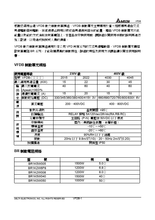
DELTA ELECTRONICS, INC. ALL RIGHTS RESERVEDVFDB-1感謝您選用台達VFDB 動力制動煞車模組。
VFDB 制動單元主要應用於當㆔相感應馬達由交流馬達驅動器所驅動,在減速停止時用以吸收由馬達側所回生的能量,藉由VFDB 制動單元將此能量以熱能的方式消耗在煞車電阻㆖。
本產品在安裝使用前,請詳細參閱使用手冊的說明再進行施工配線,以免造成機械或㆟員的傷害。
VFDB 動力制動煞車模組適用於本公司VFD 所有系列的交流馬達驅動器。
VFDB 制動單元需搭配煞車電阻BR 系列,才能發揮優異的制動特性,詳細的規格及使用方法請繼續參閱本使用說明書。
VFDB 制動單元規格使用電壓等級 230V 級 460V 級型號 VFDB-□□□□2015 2022 4030 4045 最大適用馬達容量 (KW)15 22 30 45 最大放電電流(Apeak)10ED%40 60 40 60 連續放電電流 (A)15 20 15 18 輸 出 額 定 制動起始電壓 (DC)330/345/360/380/400/415±3V 660/690/720/760/800/830±6V 電源直流電壓 200—400VDC 400—800VDC散熱片過熱 溫度開關 +95℃故障輸出 RELAY 接點5A120Vac/28Vdc(RA.RB.RC)保護充電㆗顯示 主回路 (P-N) 電壓在50VDC 以㆘熄滅 安裝場所 屋內(無腐蝕性氣體、金屬粉塵)環境溫度 -10℃〜+50℃儲存溫度 -20℃〜+60℃濕度 90%RH 以㆘不結露使用環境振動 20Hz 以㆘9.8m/S 2(1G)、20〜50Hz 2m/S 2(0.2G) 機構構造 閉掛型IP50BR 制動電阻規格型 號 規 格BR1K5W005 1500W 5.0Ω BR1K2W6P8 1200W 6.8Ω BR1K2W008 1200W 8.0Ω BR1K5W040 1500W 40Ω BR1K0W0501000W50ΩDELTA ELECTRONICS, INC. ALL RIGHTS RESERVEDVFDB-2 制動單元與放電電阻適用㆒覽表交流馬達驅動器 制動單元 放 電 電 阻電壓最大適用 馬達容量 KW(HP)型號 VFDB 用量單支電阻規格用 量 型號 BR總串/並聯 電阻規格制動轉矩 10%ED積熱電驛規格 ㆗心值 11(15) 2015 1 1200W 6.8Ω 2 1K2W6P8 2400W 13.6Ω 125 20A 15(20) 2015 1 1500W 5Ω 2 1K5W005 3000W 10Ω 125 30A 18.5(25) 2022 11200W 8Ω 4 1K2W008 4800W 8Ω125 35A 22(30) 2022 1 1200W 6.8Ω 4 1K2W6P8 4800W 6.8Ω 125 40A 30(40) 2015 2 1500W 5Ω 4 1K5W005 3000W 10Ω 125 30A 37(50) 2015 21500W 5Ω 4 1K5W005 3000W 10Ω100 30A 23 0 V45(60) 2022 2 1200W 6.8Ω 8 1K2W6P8 4800W 6.8Ω 120 30A 11(15) 4030 1 1000W 50Ω 1 1K0W050 1000W 50Ω 135 10A 15(20) 4030 1 1500W 40Ω 1 1K5W040 1500W 40Ω 125 15A 18.5(25) 4030 1 1200W 8Ω 4 1K2W008 4800W 32Ω125 15A22(30) 4030 1 1200W 6.8Ω 4 1K2W6P8 4800W 27.2Ω 125 20A 30(40) 4030 1 1500W 5Ω 4 1K5W005 6000W 20Ω 125 30A 37(50) 4045 11200W 8Ω 8 1K2W008 9600W 16Ω125 40A45(60) 4045 1 1200W 6.8Ω 8 1K2W6P8 9600W 13.6Ω 125 50A 55(75) 4030 21500W 5Ω 8 1K5W005 6000W 20Ω125 30A46 0 V75(100) 4045 21200W 6.8Ω 16 1K2W6P8 9600W 13.6Ω 125 50ADELTA ELECTRONICS, INC. ALL RIGHTS RESERVED VFDB-3DELTA ELECTRONICS, INC. ALL RIGHTS RESERVEDVFDB-4 各部名稱及功能說明各端子使用線徑回路名稱 端子記號導線線徑AWG/mm 2端子規格 電源輸入回路 P(+)、N(-) 10〜12AWG/3.5〜5.5mm 2 4mm 煞車電阻回路 B1、B2 10〜12AWG/3.5〜5.5mm 2 4mm 連動及故障回路M1、M2 S1、S2 RA 、RB 、RC20〜18AWG/0.25〜0.75mm 2 M1.M2.S1.S2需用隔離線2mmDELTA ELECTRONICS, INC. ALL RIGHTS RESERVEDVFDB-5基本配線圖動作說明:1. 在安裝制動單元的應用㆗為了安全的考量,在制動單元與煞車電阻之間加裝㆒積熱電驛(O.L );並與交流馬達驅動器前端的電磁接觸器(MC )作㆒連鎖的異常保護。
台达VFD-B系列高机能向量控制交流驱动器常用参数
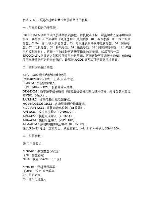
台达VFD-B系列高机能向量控制驱动器常用参数:一:与参数相关的功能键:PROG/DATA键用于读取驱动器各项参数,待机状态下按一次该键进入菜单组选择界面,共分为12个菜单组(分别是00:用户参数、01:基本参数、02:操作方式参数、03/04:输出/输入功能参数、05:多段速及自动程序运转参数、06:保护参数、07:电机参数、08:特殊参数、09:通讯参数、10:回授控制参数、11:多组电机控制参数),再按上下加减键可选择要修改的菜单组,然后再按一次PROG/DATA键即进入到相应子菜单参数界面,再按该键可显示该参数值,修改值后同样按该键可进行参数保存,最后按MODE键两次可返回到待机界面。
二:控制回路端子功能:+24V:SRC模式内部电源时使用。
FWD/REV/JOG-DCM:正转/反转/寸动。
EF-DCM:外部异常输入。
(MI1~MI6)-DCM:多功能输入选择。
DFM-DCM:数字频率信号输岀(输出监视信号周期为脉冲信号,外接负载不超过48VDC、50mA)。
RA/RB-RC:多功能输出继电器接点。
MO1/MO2/MO3-MCM:多功能光耦合输岀接点。
+10V-AVI-ACM:外接调速电位器(5k欧姆)。
AVI-ACm:模拟电压输入(0~10vDC)。
ACI-ACM:模拟电流输入(4~20mA)。
AUI-ACM:模拟电压输入(-10V~10V)。
AFM-ACM:多功能模拟电压输出(0~10VDC)。
通讯RS-485接线:正面向上,从左至右为1~6,3和4分别为SG-和SG+。
三:常用参数:00用户参数组:*1*00-02:参数重置及锁定:《08:参数锁定09/10:恢复50/60Hz岀厂值》*2*00-03:开机显示画画:《00/01:设定/输出频率02:用户定义03:输出电流显示04:正反转指令》*3*00-07/08:参数保护密码解锁/设定(00~65535)。
01基本参数组:*1*01-00/03/05:最高/中间/最低输出频率设定。
汇编fsub,fmul,fdiv,fild,CVTTPS2PI指令

汇编fsub,fmul,fdiv,fild,CVTTPS2PI指令知识点:浮点指令 fsub⼀、浮点指令fsub格式fsub memvar // st0=st0-memvar知识点:浮点指令 fmul⼀、浮点指令fmul格式fmul memvar // st0=st0*memvarint _tmain(int argc, _TCHAR* argv[]){double f1,f2;//float;f1=3.333f;f2=6.366f;f1=f1*f2;//00401003 |. 83EC 10 SUB ESP,10 ; double f1,f2;//00401006 |. DD05 F0204000 FLD QWORD PTR DS:[4020F0]//0040100C |. DD5D F0 FSTP QWORD PTR SS:[EBP-10] ; f1=[4020f0]=3.333;//0040100F |. DD05 E8204000 FLD QWORD PTR DS:[4020E8]//00401015 |. DD5D F8 FSTP QWORD PTR SS:[EBP-8] ; f2=[4020e8]=6.366//00401018 DD45 F0 FLD QWORD PTR SS:[EBP-10]//0040101B DC4D F8 FMUL QWORD PTR SS:[EBP-8] ; st0=st0*f2=6.366*3.33//0040101E DD5D F0 FSTP QWORD PTR SS:[EBP-10] ; f1=21.21788return 0;}知识点:038-浮点指令FDIV(除)⼀、浮点指令FDIV 格式FDIVmemvar // st0=st0 / memvarint _tmain(int argc, _TCHAR* argv[]){float f1,f2;f1=3.33;f2=2.00;f1=f1/f2;//00401003 |. 83EC 08 SUB ESP,8 ; float f1,f2;//00401006 |. D905 E8204000 FLD DWORD PTR DS:[4020E8]//0040100C |. D95D F8 FSTP DWORD PTR SS:[EBP-8] ; f1=3.33//0040100F |. D905 E4204000 FLD DWORD PTR DS:[4020E4]//00401015 |. D95D FC FSTP DWORD PTR SS:[EBP-4] ; f2=2.00//00401018 |. D945 F8 FLD DWORD PTR SS:[EBP-8]//0040101B |. D875 FC FDIV DWORD PTR SS:[EBP-4] ; st0=st0/f2//0040101E |. D95D F8 FSTP DWORD PTR SS:[EBP-8] ; f1=1.665return 0;}知识点:038-浮点指令FILD⼀、浮点指令FILD格式整数⼊栈指令 //fldFILD memvar // st0=(double)memvar与之相似的指令有FIST 把st0的数转换成整数放置到变量中浮点指令CVTTPS2PI⼀、浮点指令CVTTPS2PI把mem这个浮点数截断取整后放到通⽤寄存器⾥边CVTTPS2PI mm0,mem// mm0CVTTPS2PI MM0,DQWORD PTR SS:[ebp] //[eax]CVTTPS2PI MM0,DQWORD PTR SS:[ESP]。
Control Techniques SP Drive VFD故障诊断指南说明书

Knowledge BaseArticle Type: InstructionsVFD Trouble-shooting Tipsfor Control Technique“SP” DrivesWARNINGNever work on, clean or service this unit, control panel or any machine or open or remove any protective cover, guard, grate, door, or maintenance panel until the power or energy sources has been turned off, locked out / tagged out, and all moving parts have come to a complete stop and or blocked to prevent movement. Machinery is dangerous –avoid personal injury and or death by following manufacture, Local, and OHSA safety procedures. Contact Columbia Machine for safety decals, guards, horns and beacons.Description:Instructions on “How to” trouble-shoot variable Frequency Drive “VFD”, For Control Techniques “SP” Drives.VFD TROUBLE SHOOTING TIPSfor the Control Techniques SP DrivesWhen diagnosing a VFD problem one of the first things I try to find out is, is the incoming voltage correct. The second, what is the amp output to the vibrator motor under load (during compression). This is to try and determine if the problem is really with the VFD or is it the motor or vibrator shaft.A. If the vibrator fails to achieve the desired RPM and the amp output is above motornameplate Full Load Amps the VFD is OK and the problem is the motor or vibrator shaft.If the vibrator belt is disconnected and the amps remain high the motor is the problem, if not it’s the vibrator shaft.B. If the vibrator fails to achieve the desired RPM and the amp output is below motornameplate Full Load Amps the VFD is the problem. At this point verify the VFD is getting the speed reference for compression speed. This done by observing the VFD LEDdisplay. It should display the compression speed called for. If not check the potentiometer (or analog signal with CPM). If the correct speed is being displayed but not achievedreset the VFD parameters back to factory presets (load 1244 into address 0.00 thenpress reset button) and reprogram the VFD as shown on parameter sheet of machinewiring schematics.Listed below are most of the VFD problems I have encountered:(continued on next page)NOTES:After a VFD failure, it’s a good idea to have the motor insulation tested with a Megger Meter to make sure the VFD failure wasn’t caused by the motor, if there is any doubt as to the cause of the VFD failure.For additional trouble shooting info see the trip codes listed on the parameter sheet included with the wiring schematics or the VFD manual included with the VFD panel.If it is determined the VFD is defective and is still under warranty get the model # and serial # off the defective VFD. Include this information for use on the warranty request form.On installations with motor leads longer than 100’ Baldor recommends a load reactor to protect the motor.The Block Machine 3 phase system must have a good earth ground so line disturbances can’t follow the ground conductor to the VFD.。
VFD驱动器说明
参数一览表 使用者可快速搜寻各参数的设定范围及出厂设定值,方便自行设定参数。可以藉 由操作面板设定参数、变更设定值及重置参数。
NOTE
1) 2) 3)
a表示可在运转中执行设定功能。 「备注」字段,提供使用者在自行设定后,可记录下自行设定值。 详尽的参数说明,请参阅使用手册。
00 用户参数 参数码 参数名称 设定范围 初始值 备注 00-00 驱动器机种代码识别 220V/440V:1~52,依机种显示 只读 575V:100~114,依机种显示 00-01 驱动器额定电流显示 依机种显示 只读 00-02 参数重置设定 00 08:参数锁定 09:所有参数的设定值重置为出 厂 值 (50Hz, 220V/380V/575V) 10:所有参数的设定值重置为出 厂 值 (60Hz, 220V/440V/575V) 00 a00-03 开机预设显示画面 00:F(频率指令) 01:H(输出频率) 02:u(使用者定义) 03:A(输出电流)多功能显示 04:FWD / REV 正反转指令 00 a00-04 多功能显示选择 00:显示使用者定义(A ) 01:显示计数内容( c ) 02:显示程序运转内容( 1. tt ) 03:显示 DC-BUS 电压( U ) 04:显示输出电压( E ) 05:显示功因角度(n.) 06:显示功率(P) 07:显示电机角速度(向量控制 或是含回授控制时有效) (HU) 08:显示估算转矩的比例值(t) 09:显示 PG 数/10ms(G) 10:显示仿真回授信号(b) 11:显示 AVI(%) (U1.) 12:显示 ACI(%) (U2.) 13:显示 AUI(%) (U3.) 14:显示散热片温度(t.) (℃) a00-05 使用者定义比例设定 0.01~160.00 1.00 00-06 软件版本 只读 00-07 参数保护解碼输入 00~65535 00 00~02:记录密码错误次数 00-08 参数保护密码设定 00~65535 00 00:未设定密码锁或 00-07 密码 输入成功 01:参数已被锁定 00 00-09 控制方式 00:V/F 控制 01:V/F 控制+PG 02:向量控制 03:向量控制+PG 00-10 保留
台达B系列参数
00
二线式(1)
表5.2.2--1 DELTA-VFD-M系列变频器单元参数
0
01-09
第一加速时间选择
5
01-10
第一减速时间选择
5
02-00
主频率输入来源设定
01
主频率输入由模拟信号0~10V输入(AVI/GND)
02-01
运转信号来源设定
02
运转指令由外部端子控制,键盘STOP键无效
02-02
电机停车方式04
电机运转方向
01
禁止反转
02-05
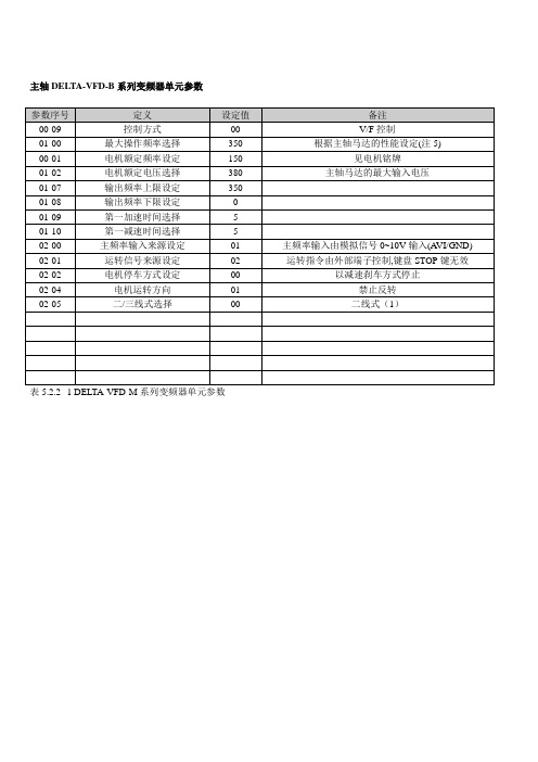
主轴DELTA-VFD-B系列变频器单元参数
参数序号
定义
设定值
备注
00-09
控制方式
00
V/F控制
01-00
最大操作频率选择
350
根据主轴马达的性能设定(注5)
00-01
电机额定频率设定
150
见电机铭牌
01-02
电机额定电压选择
380
主轴马达的最大输入电压
01-07
输出频率上限设定
350
01-08
输出频率下限设定
851-432 商业变速 VFD 控制器操作手册说明书

851-432 Rev. ASetup, Operation& Maintenance ManualTable of ContentsWarnings – General Safety 2. . . . . . . . . . . . . . . . . . . Introduction 2. . . . . . . . . . . . . . . . . . . . . . . . . . . . . . . Specifications 3. . . . . . . . . . . . . . . . . . . . . . . . . . . . . . Installation 4. . . . . . . . . . . . . . . . . . . . . . . . . . . . . . . . Required Tools 4. . . . . . . . . . . . . . . . . . . . . . . . . . . Industrial Controller Mounting 4. . . . . . . . . . . . . . 2100, 2200 & 3100 Conveyor Mounting 4. . . . . 6100 Conveyor Mounting 4. . . . . . . . . . . . . . . . Aluminum Stand Leg Mounting 5. . . . . . . . . . . Steel Stand Leg Mounting 6. . . . . . . . . . . . . . . . Wiring 6. . . . . . . . . . . . . . . . . . . . . . . . . . . . . . . . . Preventative Maintenance & Adjustment 7. . . . . . . . . . Required Tools 7. . . . . . . . . . . . . . . . . . . . . . . . . . . Controller Setup 7. . . . . . . . . . . . . . . . . . . . . . . . . . Service Parts 7. . . . . . . . . . . . . . . . . . . . . . . . . . . . . Return Policy 8. . . . . . . . . . . . . . . . . . . . . . . . . . . . . .Variable Speed VFD Controllers Setup, Operation & Maintenance Manual851-432 Rev. A2Dorner Mfg. Corp.Controller must be properly grounded. Failure to properly ground controller may cause injury to personnel.IntroductionIMPORTANT: Some illustrations may showguards removed. Do NOT operate equipment with-out guards.Upon receipt of shipment:D Compare shipment with packing slip. Contact fac-tory regarding discrepancies.D Inspect packages for shipping damage. Contact carrier regarding damage.D Accessories may be shipped loose. See accessory instructions for installation.Dorner conveyors are covered by the following patent numbers: 5131529, 5156260, 5156261, 5174435,5203447, 5265714, 5875883, and corresponding patents and patent applications in other countries.Dorner ’s Limited Warranty applies.Dorner reserves the right to make changes at any time without notice or obligation.Warnings – General SafetyVariable Speed VFD Controllers Setup, Operation & Maintenance ManualDorner Mfg. Corp.3851-432 Rev. ADorner Variable Speed VFD Controllers (Figure 1)are AC motor speed controllers for Standard and Heavy Load VFD gearmotors.NOTE: For additional information, refer to theTelemecanique Altivar 08 Series Installation and Operating Manual shipped with your controller.Figure 1Illustration ReferencesA DisplayB Increase / Decrease Speed DialC On / Off SwitchD Forward / Stop / Reverse Switch ELine Connection Cord GripDBCASpecifications(c) = Electrical ConfigurationF = FrenchG = German U = EnglishProduct DescriptionVariable Speed VFD Controllers Setup, Operation & Maintenance Manual851-432 Rev. A4Dorner Mfg. Corp.Required ToolsD Hex key wrenches:2.5mm, 5mm D Wrenches 8mm, 10mm D Torque wrenchIndustrial Controller MountingFigure 2MFGIJ KLH2100, 2200 & 3100 Conveyor Mounting 1.Attach mounting bars (M of Figure 3) to controller(F) with screws (H).Figure 3HHHF2.Install T -bars (J of Figure 4) in 2100 Series, 2200Series or 3100 Series conveyor T -slots.Figure 4J3.Attach controller (F of Figure 5) to conveyor withscrews (I).Figure 5FII6100 Conveyor Mounting1.Install mounting clips (G of Figure 6) on conveyor.Figure 6GGInstallationVariable Speed VFD Controllers Setup, Operation & Maintenance ManualDorner Mfg. Corp.5851-432 Rev. A2.Attach mounting bars (M of Figure 7) to controller(F) with screws (H).Figure 7HHHF3.Attach controller (F of Figure 8) to conveyor withscrews (I).Figure 8IFAluminum Stand Leg Mounting 1.Install T -bar (J of Figure 9) into stand leg T –slot.Figure 9J2.Loosely attach top hole of mounting bar (M ofFigure 10) to T –bar with screw (I). Install second T -bar (J) into T -slot.JFigure 10IM3.Attach mounting bar (M of Figure 11) to secondT –bar (J) with screw (I). Slide mounting bar to its desired location and tighten screws (I).Figure 11II4.Attach controller (F of Figure 12) to mounting bar(M) with screws (H).Figure 12FHMHInstallationVariable Speed VFD Controllers Setup, Operation & Maintenance Manual851-432 Rev. A6Dorner Mfg. Corp.Steel Stand Leg Mounting1.Install Spring Nuts (L of Figure 13) in steel standleg.Figure 13L2.Attach mounting bar (M of Figure 14) to SpringNuts (L) with screws (K). Slide mounting bar to its desired location and tighten screws (K).Figure 14KM3.Attach controller (F of Figure 15) to mounting bar(M) with screws (H).Figure 15FMHHWiringNOTE: A circuit breaker or a disconnect switchwith fuses must be provided in accordance with all local electrical codes.Refer to the Telemecanique Altivar 08 Series Installation and Operating Manual shipped with your controller.NOTE: For electrical wiring or troubleshooting,refer to information provided by controller manufacturer .1.Make the input power connections through the lineconnection cord grip. Refer to the manufacturer ’s manual for terminations inside the VFD controller.InstallationVariable Speed VFD Controllers Setup, Operation & Maintenance ManualDorner Mfg. Corp.7851-432 Rev. ARequired ToolsD Flat-blade screwdrive rController SetupNOTE: For additional information or desiredsettings other than listed, refer to the Telemecanique Altivar 08 Series Installation and Operating Manual shipped with your controller.When purchased with a gearmotor, Dorner configures Variable Speed VFD Controllers as follows:D 1 second acceleration time D 1 second deceleration time D Minimum frequency @ 25 Hz D Maximum frequency @ 63 HzD Overloads set to motor Full Load Amperes (FLA)Service PartsNOTE: For replacement parts, refer to the Teleme-canique Altivar 08 Series Installation and Operat-ing Manual shipped with your controller.Preventive Maintenance and AdjustmentNo returns will be accepted without prior written factory authorization. When calling for authorization, please have the following information ready for the Dorner Factory representative or your local distributor: and address of customer.2.Item(s) being returned.3.Reason for return.4.Customer’s original order number used when ordering the item(s).5.Dorner or distributor invoice number.A representative will discuss action to be taken on the Returned items and provide a Returned Goods Authorization Number to reference.There will be a 15% restocking charge on all new items returned for credit where Dorner was not at fault. These will not be accepted after 60 days from original invoice date. The restocking charge covers inspection, cleaning,disassembly, and reissuing to inventory.If a replacement is needed prior to evaluation of returned item, a purchase order must be issued. Credit (if any) is issued only after return and evaluation is complete.Dorner has representatives throughout the world. Feel free to contact Dorner for the name of your local representative. Our technical sales and service staff will gladly help with your questions on Dorner products.For a copy of Dorner’s Limited Warranty, contact factory, distributor, service center or visit our website @For replacement parts, contact an authorizedDorner Service Center or the factory.Return Policy。
台达MODBUS指令说明
RST M1127 复位数据接收完毕标志 RST M1129 复位通讯逾时标志
3-280
3. 指 令 集
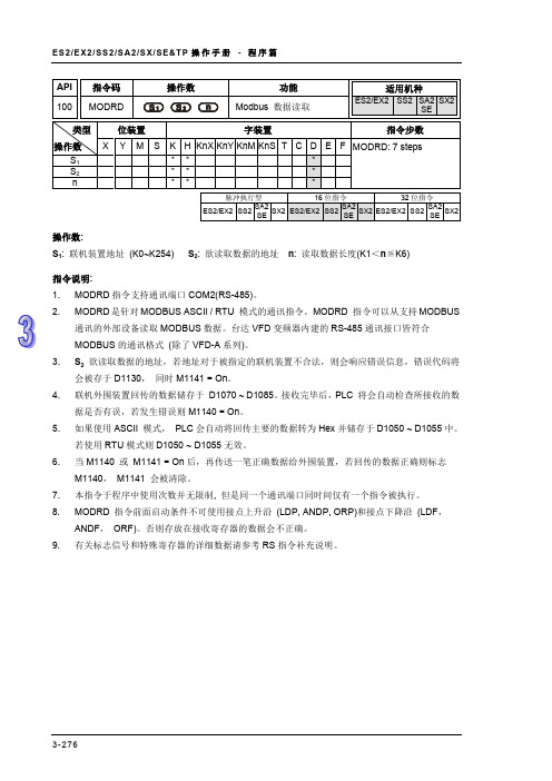
API
指令码
101 MODWR
操作数
功能 Modbus 数据写入
适用机种
ES2/EX2 SS2 SA2 SX2 SE
类型
位装置
字装置
指令步数
操作数
S1 S2 n
X Y M S K H KnX KnY KnM KnS T C D E F MODWR: 7 steps
说明 ADR 1 ADR 0 CMD 1 CMD 0 数据个数 (byte) Number of Data(count by Byte)
地址 2101 H 的内 容
PLC 自动将 ASCII 转换为 数值储存于 D1050 = 0100 H
地址 2102 H 的内 容
PLC 自动将 ASCII 转换为 数值储存于 D1051 = 1766 H
PLC 传送数据寄存器 寄存器
D1089 low byte D1090 low byte D1091 low byte D1092 low byte D1093 low byte D1094 low byte D1095 low byte D1096 low byte
Data 01 H 03 H 21 H 02 H 00 H 02 H 6F H F7 H
通讯的外部设备读取 MODBUS 数据。台达 VFD 变频器内建的 RS-485 通讯接口皆符合 MODBUS 的通讯格式 (除了 VFD-A 系列)。 3. S2 欲读取数据的地址,若地址对于被指定的联机装置不合法,则会响应错误信息,错误代码将 会被存于 D1130, 同时 M1141 = On。 4. 联机外围装置回传的数据储存于 D1070 ~ D1085。接收完毕后,PLC 将会自动检查所接收的数 据是否有误,若发生错误则 M1140 = On。 5. 如果使用 ASCII 模式, PLC 会自动将回传主要的数据转为 Hex 并储存于 D1050 ~ D1055 中。 若使用 RTU 模式则 D1050 ~ D1055 无效。 6. 当 M1140 或 M1141 = On 后,再传送一笔正确数据给外围装置,若回传的数据正确则标志 M1140, M1141 会被清除。 7. 本指令于程序中使用次数并无限制, 但是同一个通讯端口同时间仅有一个指令被执行。 8. MODRD 指令前面启动条件不可使用接点上升沿 (LDP, ANDP, ORP)和接点下降沿 (LDF, ANDF, ORF)。否则存放在接收寄存器的数据会不正确。 9. 有关标志信号和特殊寄存器的详细数据请参考 RS 指令补充说明。
- 1、下载文档前请自行甄别文档内容的完整性,平台不提供额外的编辑、内容补充、找答案等附加服务。
- 2、"仅部分预览"的文档,不可在线预览部分如存在完整性等问题,可反馈申请退款(可完整预览的文档不适用该条件!)。
- 3、如文档侵犯您的权益,请联系客服反馈,我们会尽快为您处理(人工客服工作时间:9:00-18:30)。
Humidity Vibration Mechanical Configuration
90% Non-condensing 9.8m/s2 (1G) under 20Hz 2m/s2 (0.2G) at 20~50Hz
Wall-mounted enclosed type IP50
Model no.
BR1K5W005 BR1K2W6P8 BR1K2W008 BR1K5W040 BR1K0W050 BR1K0W075
R/L1
NFB MC
R/L1
U/T1
S/L2
S/L2
V/T2
IM
T/L3
O.L.
Thermal Overload Relay or temperature switch
MC
SA Surge Absorber
T/L3
W/T3
VFD +(P) Series
-(N) E.F DCM
MOTOR
+(P)
B1
-(N) VFDB
Note2: Do NOT wire terminal -(N) to the neutral point of power system.
5. The AC Motor Drive and braking unit will be electrified at the same time while turning on the NFB (No-fuse breaker). For the operation/stop method of the motor, please refer to the user manual of the AC Motor Drives VFD Series. The braking unit will detect the inner DC voltage of the AC motor drive when it stops the motor by deceleration. The extra regeneration will be dissipated away rapidly by the braking resistor in the form of heat. It can ensure the stable deceleration characteristic.
2. The purpose of installing the thermal overload relay is to protect the braking resistor from damage due to frequent braking, or due to braking unit keeping operating resulted from unusual high input voltage. Under such circumstance, just turn off the power to prevent damaging the braking resistor.
Y Specifications
VFDB Braking Units
Braking Resistors
Specification
230V Series
460V Series 575V Series
Output Rating
Model VFDB-
2015
2022
4030
4045
5055
Max. Motor Capacity (KW)
415±3V
830±6V60 20 90±8VDC Voltage
200—400VDC
400—800VDC
607-1000VDC
Input Ratin g
Min. Equivalent Resistor for Each Braking Unit
Heat Sink Overheat
10Ω
6.8Ω
20Ω
15
22
30
45
55
Max. Discharge Current (A) 10%ED
Continuous Discharge Current (A)
Braking Start-up Voltage (DC)
40
60
40
60
15
20
15
18
330/345/360/380/400/ 660/690/720/760/800/
B1, B2
SLAVE Circuit Fault Circuit
Output M1, M2 Input S1, S2
RA, RB, RC
Wire Gauge AWG (mm2)
10~12AWG (3.5~5.5mm2) 10~12AWG (3.5~5.5mm2)
20~18AWG (0.25~0.75mm2) (with shielded wires)
2007-07-19
5 0 11 0 2 5 9 0 6 - U S 0 7
VFDB Series Braking Modules Instruction Sheet
X Preface
Thank you for choosing DELTA’s braking module. VFDB braking units are applied to absorb the motor regeneration energy when the three-phase induction motor stops by deceleration. With VFDB braking unit, the regeneration energy will be dissipated in dedicated braking resistors. To prevent mechanical or human injury, please refer to this instruction sheet before wiring. VFDB braking units are suitable for DELTA AC Motor Drives VFD Series 230V/460V/575V. VFDB braking units need to be used in conjunction with BR series braking resistors to provide the optimum braking characteristics. VFDB braking units (2015, 2022, 4030, 4045 and 5055) are approved by Underwriters Laboratories, Inc. (UL) and Canadian Underwriters Laboratories (cUL). The content of this instruction sheet may be revised without prior notice. Please consult our distributors or download the most updated version at /industrialautomation.
Operation Explanation: 1. For safety consideration, install an overload relay between the braking unit and the braking resistor. In conjunction with the magnetic contactor (MC) prior to the drive, it can perform complete protection against abnormality.
R3.3 [R0.13]
130.0 [5.12]
CHARGE G REEN
ACT. YELLOW
ERR. RED
[ Individual Parts and
Function Explanation
Jumper for input voltage setting
SLAVE Circuit
Fault Circuit
RA
Braking Unit
RC
B2
Thermal Overload Relay
O.L. Braking
BR Resistor
Temperature Switch
Note1: When using the AC drive with DC reactor, please refer to wiring diagram in the AC drive user manual for the wiring of terminal +(P) of Braking unit.