LM190E08-TLL2_CAS
FLUKE(福禄克)190系列示波器 中文说明书 上册
2011 年 5 月(Simplified Chinese)© 2011 Fluke Corporation. 版权所有。
荷兰印刷。
规格如有更改,恕不另行通知。
所有产品名称均为其所属公司的商标。
ScopeMeter 190 Series IIFluke 190-062, -102, -104, -202, -204, -502用户手册上 册有限保修及服务范围在正常使用与维修情况下,Fluke 保证每一产品均无材料和工艺问题。
自发货之日算起,测试工具保修期为三年,附件保修期为一年。
零配件及产品修理与维护的保修期为 90 天。
此保修仅限于原始购买者或 Fluke 指定经销商的产品使用客户;而不适用于保险丝和普通电池,或任何 Fluke 认为因错误使用、改装、疏忽或因事故或非正常条件下操作或处理而导致损坏的产品。
在 90 天内,Fluke 保证软件运行符合其功能规范,并且保证软件正确记录于完好无损的介质上。
Fluke 不保证软件毫无差错或无操作中断情况。
Fluke 指定经销商只能向产品使用客户对新的或未使用过的产品提供保修,而无权以 Fluke 的名义扩充或更改保修内容。
从 Fluke 指定的销售渠道或按相应国际价格购买的产品可以得到保修。
当产品在一个国家购买而要在另一个国家修理时,Fluke 保留向客户收取修理/更换零配件费用的权利。
对于在保修期内送回 Fluke 指定的维修中心,要求按原价退款或者免费维修或更换的有故障产品,Fluke 的保修义务是有限的。
要获得保修服务,请就近联系 Fluke 指定的维修中心,或在附上故障说明、邮费和预付保险(目的地交货价)后,将产品寄往最近的 Fluke 指定的维修中心。
Fluke 对运输中可能出现的损坏情况不承担责任。
产品在维修后,将寄回给客户,邮费预付(目的地交货价)。
如果 Fluke 确定产品故障是由于错误使用、改装、事故或非正常情况下使用或操作造成的,Fluke 将提供维修费用预算并在得到认可后方进行维修。
EMI产品手册08版
目录交流单相通用滤波器 (2)交流单相高性能滤波器 (5)交流单相超高性能滤波器 (7)交流三相三线滤波器 (10)交流三相四线滤波器 (12)变频器输入端专用型滤波器 (14)变频器输出端专用型滤波器 (16)直流滤波器 (18)PCB交流插针型滤波器 (21)IEC标准插座形滤波器 (22)军用交流单相高性能滤波器 (24)军用交流三相滤波器 (27)军用直流滤波器 (30)屏蔽室电源滤波器双线系列 (33)屏蔽室电源滤波器单线系列 (34)电快速瞬变脉冲群抑制器 (36)浪涌抑制器 (37)滤波器基础知识介绍 (39)产品特点▲ 对差模和共模干扰具有良好的抑制特性。
▲ 泄漏电流小。
▲ 体积小,重量轻,性能可靠、价格低廉。
Features▲ General purpose filters with a good suppression tocommon-mode and differential-mode interference.▲ Lower leakage current.▲ Compact, light weight, reliable and low cost技术指标额定电压Rated V oltage 115/250V AC 额定电流Rated Current 3A—300A 工作频率Operating Frequency 50/60Hz 耐压测试(一分钟) 1450VDC (line/line ) Test V oltage (1min ) 1500V AC (line/ground ) 泄漏电流Leakage Current : <0.5mA(250V AC/50Hz) 温度范围Temperature Range -25℃/+85℃ 端接方式Connections应用场合开关电源、UPS 电源、医疗设备、仪器仪表等电力电子设备。
ApplicationSwitching-mode power supply ,UPS ,medical equipments and electronic instruments etc. 电路原理图Electrical Schematics【 A 】 【 B 】插入损耗(dB ) 共模/差模 (CM/DM )额定 电流 外形尺寸原理 电路 测试频率(MHz)型 号 (A) 图号图号 06 07 080.010.050.100.150.5 1.0 5.0 10 20 30F-FAB1-03-?? 3 B1 A 0811/523/1029/1532/1937/2941/3649/53 52/55 55/5450/52F-FAB1-06-?? 6 B1 A 085/4 13/919/1522/1831/2835/3349/55 52/57 56/5658/52F-FAB2-03-?? 3 B2 A 0811/523/1029/1532/1937/2941/3649/53 52/55 55/5450/52F-FAB2-06-?? 6 B2 A 085/4 13/919/1522/1831/2835/3349/55 52/57 56/5658/52F-LAB1-02-?? 2 B1 A 0821/728/1530/2031/2136/5342/5357/63 69/69 62/6862/68F-LAB1-03-?? 3 B1 A 0818/625/1527/1929/2133/4839/5053/63 63/69 69/6568/68F-LAB2-02-?? 2 B2 A 0821/728/1530/2031/2136/5342/5357/63 69/69 62/6862/68F-LAB2-03-?? 3 B2 A 0818/625/1527/1929/2133/4839/5053/63 63/69 69/6568/68F-FAC1-03-?? 3 C1 A 07 0816/629/1135/1639/1945/3147/4352/51 53/55 52/5652/56交流单相通用型滤波器General Purpose Filters交流单相通用滤波器参数表General Purpose Filter Parameter ListFTF EMI电源滤波器插入损耗(dB)共模/差模(CM/DM)测试频率(MHz)型号额定电流(A)外形尺寸图号原理电路类型06 07 080.010.050.100.150.5 1.0 5.0 10 20 30 F-FAC1-06-?? 6 C1 A 07 085/4 13/919/1522/1831/2835/3349/55 52/57 56/5658/52 F-FAC2-03-?? 3 C2 A 07 0816/629/1135/1639/1945/3147/4352/51 53/55 52/5652/56 F-FAC2-06-?? 6 C2 A 07 085/4 13/919/1522/1831/2835/3349/55 52/57 56/5658/52 F-LAC1-03-?? 3 C1 A 07 0826/637/1038/1641/1945/3050/4057/63 60/60 58/6055/62 F-LAC1-06-?? 6 C1 A 07 0820/630/1132/1634/1938/2942/3646/55 50/53 52/5452/58 F-LAC2-03-?? 3 C2 A 07 0826/637/1038/1641/1945/3050/4057/63 60/60 58/6055/62 F-LAC2-06-?? 6 C2 A 07 0820/630/1132/1634/1938/2942/3646/55 50/53 52/5452/58 F-FBD1-06-?? 6 D1 B 06 07 11/723/1830/2132/2237/5042/5353/63 53/63 68/6562/68 F-FBD1-10-?? 10 D1 B 06 07 4/5 16/1722/2124/2530/4434/4746/53 53/63 68/6562/64 F-FBD2-06-?? 6 D2 B 06 07 11/723/1830/2132/2237/5042/5353/63 53/63 68/6562/68 F-FBD2-10-?? 10 D2 B 06 07 4/5 16/1722/2124/2530/4434/4746/53 53/63 68/6562/64 F-LBD1-06-?? 6 D1 B 06 07 21/833/1836/2438/2542/5647/5859/69 59/63 68/6062/65 F-LBD1-10-?? 10 D1 B 06 07 20/825/1928/2429/2533/4738/5053/59 57/63 62/6362/65 F-LBE2-15-?? 15 E2 B 06 07 20/825/1928/2429/2533/4738/5053/59 57/63 62/6362/65 F-LBE2-20-?? 20 E2 B 06 07 20/825/1928/2429/2533/4738/5053/59 57/63 62/6362/65 F-FBE2-30-?? 30 E2 B 06 07 3/8 13/2018/2520/2525/3528/3740/45 43/51 50/5362/66 F-LBE2-30-?? 30 E2 B 06 07 10/815/1918/2020/3123/4230/4350/57 57/63 68/6870/70 F-FBF2-40-?? 40 F2 B 06 3/8 13/2018/2520/2525/3528/3740/45 43/51 50/5362/66 F-LBF2-40-?? 40 F2 B 06 10/815/1918/2020/3123/4230/4350/57 57/63 68/6870/70 F-FBG2-60-?? 60 G2 B 06 3/8 13/2018/2520/2525/3528/3740/45 43/51 50/5362/66 F-LBG2-60-?? 60 G2 B 06 10/815/1918/2020/3123/4230/4350/57 57/63 68/6870/70 F-FBH2-100-?? 100 H2 B 06 3/8 13/2018/2520/2525/3528/3740/45 43/51 50/5362/66 F-LBH2-100-?? 100 H2 B 06 10/815/1918/2020/3123/4230/4350/57 57/63 68/6870/70 F-FBH2-150-?? 150 H2 B 06 3/8 13/2018/2520/2525/3528/3740/45 43/51 50/5362/66 F-LBH2-150-?? 150 H2 B 06 10/815/1918/2020/3123/4230/4350/57 57/63 68/6870/70 F-LBZ2-300-?? 300 Z2 B 06 10/815/1918/2020/3123/4230/4350/57 57/63 68/6870/70 F-LBP1-10-?? 10 P1 B 06 07 23/828/1930/2231/2436/5041/6060/64 63/69 68/7068/68 F-LBP1-20-?? 20 P1 B 06 07 18/825/1826/2328/2632/4738/5053/63 60/68 68/7062/62 F-FAM1-03-?? 3 M1 A 06 07 0811/523/1029/1532/1937/2941/3649/53 52/55 55/5450/52【图B1】【图B2】【图C1】【图C2】外形尺寸交流单相通用滤波器参数表General Purpose Filter Parameter List【图D1】 【图E2】 【图F2】【图G2】 【图H2】【图Z2】 【图P1】68【图M1】外形尺寸产品特点▲双级共模、一级共模一级差模滤波电路,具有良好的共模和差模干扰抑制特性。
道尔康(Dow Corning)TB TL CER玻璃粘合剂橙色版说明书

Page: 1 of 8Version: 1.4Revision Date: 2023/02/28 DOW CORNING(R) TB/TL/CER SEALANT ALMOND1.IDENTIFICATION OF THE SUBSTANCE AND OF THE COMPANYMSDS No.: 04045034SUPPLIER:Dow Corning Canada Inc.15-6400 Millcreek Drive, Suite 416 Mississauga, ON, Canada L5N 3E7Prepared by Product Safety:NEWALTA:Revision Date:(800)248-2481(800)567-74552023/02/28MANUFACTURER:Dow Corning CorporationSouth Saginaw RoadMidland, Michigan 4868624 Hour Emergency Telephone: (989) 496-5900WHMIS CLASSIFICATION: Class D, Division 2, Subdivision A.Class D, Division 2, Subdivision B.Material Usage: Sealant and adhesive2.HAZARDS IDENTIFICATIONEMERGENCY OVERVIEWGeneric Description: Silicone elastomerPhysical Form: PasteColour: AlmondOdour: Acetic acidAcetic acid is formed upon contact with water or humid air. Provide adequate ventilation to control exposures within guidelines of OSHA PEL: TWA 10 ppm and ACGIH TLV: TWA 10 ppm, STEL 15 ppm.++++++++++++++++++++++++++++++++++++++++++++POTENTIAL HEALTH EFFECTSAcute EffectsEye: Direct contact may cause moderate irritation.Skin: May cause moderate irritation.Inhalation: Irritates respiratory passages very slightly.Oral: Low ingestion hazard in normal use.Prolonged/Repeated Exposure EffectsPage: 2 of 8Version: 1.4 DOW CORNING(R) TB/TL/CER SEALANT ALMONDSkin: No known applicable information.Inhalation: No known applicable information.Oral: No known applicable information.Signs and Symptoms of OverexposureNo known applicable information.Medical Conditions Aggravated by ExposureNo known applicable information.The above listed potential effects of overexposure are based on actual data, results of studies performed upon similar compositions, component data and/or expert review of the product. Please refer to Section 11 for the detailed toxicology information.POSITION/INFORMATION ON INGREDIENTSCAS Number Wt % Component Name7631-86-9 10.0 - 30.0 Silica, amorphous4253-34-3 1.0 - 5.0 Methyltriacetoxysilane17689-77-9 1.0 - 5.0 Ethyltriacetoxysilane556-67-2 0.5 - 1.5 OctamethylcyclotetrasiloxaneThe ingredients listed above are controlled products as defined in CPR, am. SOR/88-555.4.FIRST AID MEASURESEye: Immediately flush with water for 15 minutes. Get medical attention.Skin: Remove from skin and wash thoroughly with soap and water or waterless cleanser. Getmedical attention if irritation or other ill effects develop or persist.Inhalation: No first aid should be needed.Oral: No first aid should be needed.Notes to Physician: Treat according to person's condition and specifics of exposure.5.FIRE FIGHTING MEASURESFlash Point: Not applicable.Page: 3 of 8Version: 1.4 DOW CORNING(R) TB/TL/CER SEALANT ALMONDAutoignition Temperature: Not available.Flammability Limits in Air: Not available.Extinguishing Media: On large fires use dry chemical, foam or water spray. On small fires use carbon dioxide(CO2), dry chemical or water spray. Water can be used to cool fire exposed containers. Fire Fighting Measures: Self-contained breathing apparatus and protective clothing should be worn in fighting largefires involving chemicals. Determine the need to evacuate or isolate the area according toyour local emergency plan. Use water spray to keep fire exposed containers cool. Unusual Fire Hazards: None.6.ACCIDENTAL RELEASE MEASURESContainment/Clean up: Observe all personal protection equipment recommendations described in Sections 5 and 8.Wipe up or scrape up and contain for salvage or disposal. Clean area as appropriate sincespilled materials, even in small quantities, may present a slip hazard. Final cleaning mayrequire use of steam, solvents or detergents. Dispose of saturated absorbant or cleaningmaterials appropriately, since spontaneous heating may occur. Local, provincial, federal lawsand regulations may apply to releases and disposal of this material, as well as those materialsand items employed in the cleanup of releases.Note: See section 8 for Personal Protective Equipment for Spills. Call (989) 496-5900, if additional information is required.7.HANDLING AND STORAGEUse with adequate ventilation. Product evolves acetic acid (HOAc) when exposed to water or humid air. Provide ventilation during use to control HOAc within exposure guidelines or use respiratory protection. Avoid eye contact. Keep container closed and store away from water or moisture.8.EXPOSURE CONTROLS / PERSONAL PROTECTIONComponent Exposure LimitsConsult local authorities for acceptable provincial values.Name Exposure LimitsCAS Number Component4253-34-3Methyltriacetoxysilane See acetic acid comments.LD50: 1,602 mg/kg - Oral Rat17689-77-9Ethyltriacetoxysilane See acetic acid comments.LD50: 1,462 mg/kg - Oral Rat556-67-2Octamethylcyclotetrasiloxane Dow Corning guide: TWA 10 ppm.Page: 4 of 8Version: 1.4 DOW CORNING(R) TB/TL/CER SEALANT ALMONDLC50: 36 mg/L - Inhalation Rat ; 4hr vaporLD50: > 5,000 mg/kg - Oral RatLD50: > 4,640 mg/kg - Dermal Rabbit7631-86-9Silica, amorphous OSHA PEL (final rule): TWA 80mg/m3/%SiO2. NIOSHREL: TWA 6mg/m3.LD50: > 5,000 mg/kg - DermalAcetic acid is formed upon contact with water or humid air. Provide adequate ventilation to control exposures within guidelines of OSHA PEL: TWA 10 ppm and ACGIH TLV: TWA 10 ppm, STEL 15 ppm.Engineering ControlsLocal Ventilation: None should be needed.General Ventilation: Recommended.Personal Protective Equipment for Routine HandlingEyes: Use proper protection - safety glasses as a minimum.Skin: Wash at mealtime and end of shift. Contaminated clothing and shoes should be removed as soon as practical and thoroughly cleaned before reuse. Chemical protective gloves arerecommended.Suitable Gloves: Avoid skin contact by implementing good industrial hygiene practices and procedures. Select and use gloves and/or protective clothing to further minimize the potential for skin contact.Consult with your glove and/or personnel protective equipment manufacturer for selection ofappropriate compatible materials.Inhalation: No respiratory protection should be needed.Suitable Respirator: None should be needed.Personal Protective Equipment for SpillsEyes: Use proper protection - safety glasses as a minimum.Skin: Wash at mealtime and end of shift. Contaminated clothing and shoes should be removed as soon as practical and thoroughly cleaned before reuse. Chemical protective gloves arerecommended.Inhalation/SuitableNo respiratory protection should be needed.Respirator:Precautionary Measures: Avoid eye contact. Use reasonable care.Page: 5 of 8Version: 1.4DOW CORNING(R) TB/TL/CER SEALANT ALMONDComments: Product evolves acetic acid (HOAc) when exposed to water or humid air. Provide ventilation during use to control HOAc within exposure guidelines or use respiratory protection. Note: These precautions are for room temperature handling. Use at elevated temperature or aerosol/spray applications may require added precautions.9.PHYSICAL AND CHEMICAL PROPERTIESPhysical Form: PasteColor: AlmondOdor: Acetic acidOdor Threshold: Not available.Specific Gravity @ 25°C: 1.04Viscosity: Not available.Freezing/Melting Point: Not available.Boiling Point: Not available.Vapor Pressure @ 25°C: Not available.Vapor Density: Not available.Evaporation Rate: Not available.Solubility in Water: Not available.Not available.Coefficient of Water/OilDistribution:pH: Not available.Volatile Content: Not available.Flash Point: Not applicable.Autoignition Temperature: Not available.Flammability Limits in Air: Not available.Note: The above information is not intended for use in preparing product specifications. Contact Dow Corning before writing specifications.10.STABILITY AND REACTIVITYChemical Stability: Stable.HazardousHazardous polymerization will not occur.Polymerization:Conditions to Avoid: None.Materials to Avoid: Oxidizing material can cause a reaction. Water, moisture, or humid air can cause hazardous vapors to form as described in Section 8.Hazardous Decomposition ProductsThermal breakdown of this product during fire or very high heat conditions may evolve the following decomposition products: Carbon oxides and traces of incompletely burned carbon compounds. Formaldehyde. Silicon dioxide. Metal oxides.Page: 6 of 8Version: 1.4 DOW CORNING(R) TB/TL/CER SEALANT ALMOND11.TOXICOLOGICAL INFORMATIONComponent Toxicology InformationRecent results from a 2 year repeated vapour inhalation exposure study to rats of octamethylcyclotetrasiloxane (D4) indicate effects (benign uterine adenomas) in the uterus of female animals. These effects, which have been shown to be rat-specific, occur at the highest exposure dose (700 ppm) only, a level that greatly exceeds typical workplace or consumer exposures. Industrial, commercial, or consumer uses of products containing D4 do not represent a risk to humans.Octamethylcyclotetrasiloxane administered to rats by inhalation at concentrations of 500 and 700 ppm resulted in statistically significant decreases in the number of pups born and the live litter size in both the first and second generations. Prolonged estrous cycles, and decreased mating and fertility indices were observed following 700 ppm exposure in the second generation only. There were also increases in the incidence of deliveries of offspring extending over an unusually long time period (dystocia). Subsequent mode of action work demonstrated the effect on reproduction in female rats is due to delayed ovulation caused by a treatment-related delay in or blockage of the luteinizing hormone (LH) surge on the day of proestrus. This mode of action is not considered relevant to humans.Special Hazard Information on ComponentsReproductive EffectsCAS Number Wt % Component Name556-67-2 0.5 - 1.5 Octamethylcyclotetrasiloxane Evidence of reproductive effects inlaboratory animals.12.ECOLOGICAL INFORMATIONEnvironmental Fate and DistributionComplete information is not yet available.Environmental EffectsComplete information is not yet available.Fate and Effects in Waste Water Treatment PlantsComplete information is not yet available.Ecotoxicity Classification CriteriaHazard Parameters (LC50 or EC50) High Medium LowAcute Aquatic Toxicity (mg/L) <=1 >1 and <=100>100Acute Terrestrial Toxicity <=100 >100 and <= 2000>2000Page: 7 of 8Version: 1.4 DOW CORNING(R) TB/TL/CER SEALANT ALMONDThis table is adapted from "Environmental Toxicology and Risk Assessment", ASTM STP 1179, p.34, 1993.This table can be used to classify the ecotoxicity of this product when ecotoxicity data is listed above. Please read the other information presented in the section concerning the overall ecological safety of this material.13.DISPOSAL CONSIDERATIONSCan be incinerated in accordance with local regulations.Call local hazardous waste disposal company or provincial waste authorities for more information.14.TRANSPORT INFORMATIONCanada Road (Based on IMDG Regulations)Not subject to local road regulations.Ocean Shipment (IMDG)Not subject to IMDG code.Air Shipment (IATA)Not subject to IATA regulations.Call Dow Corning Transportation, (989) 496-8577, if additional information is required.15.REGULATORY INFORMATIONThis product has been classified in accordance with the hazard criteria of the CPR, and the MSDS contains all the information required by the CPR.WHMIS CLASSIFICATION: Class D, Division 2, Subdivision A. Class D, Division 2, Subdivision B.DSL STATUS: All chemical substances in this material are included on or exempted from the DSL.Page: 8 of 8Version: 1.4 DOW CORNING(R) TB/TL/CER SEALANT ALMOND16.OTHER INFORMATIONPrepared by: Dow Corning CorporationThese data are offered in good faith as typical values and not as product specifications. No warranty, either expressed or implied, is hereby made. The recommended industrial hygiene and safe handling procedures are believed to be generally applicable. However, each user should review these recommendations in the specific context of the intended use and determine whether they are appropriate.(R)indicates Registered Trademark。
EGIL200电路保护器分析仪说明书

EGIL200 Circuit breaker analyser DESCRIPTIONEGIL200 is the first incarnation in a new range of circuit breaker analysers from Megger. It has been designed in close cooperationwith global industry reference groups drawing experience from the market leading and hugely successful Megger TM series of circuit breaker analysers.The emphasis in the development of the EGIL200 has been on ease of use, ensuring that the time spent on setting up measurements is kept to a minimum. As such, with the EGIL200, you can get your test results done in no time.Connection to the test object has also been streamlined and with only one hook-up, all following operations or measurements can be made:1.Timing of main and PIR contacts 2.Coil current analysis of close, open 1 and 2 coils 3.Station voltage measurements 4.Motion measurements 5.Motor current measurement 6.Minimum pickup voltage test for close, open 1 and open 2The patented DualGround™ timing using the DCM module makes the testing safe and time saving by keeping the circuit breaker grounded on both sides throughout the test. The DCM module uses a measuring technology called Dynamic Capacitive Measurement.With both main instrument and accessories designed for the most demanding field conditions, EGIL200 is your complete toolbox for daily, hassle-free circuit breaker condition assessments.M egger ..■Mid-range circuit breaker analyser providing a new level of accuracy to your standard measurements ■Intuitive operation offers final measurement results with a minimum of user interaction ■Measurement performance inherited from market leader Megger TM series circuit breaker analysers■Instrument and accessories designed for the most demanding field conditions■Easy-to-use and intuitive interfaceBENEFITS EGIL200 offers all standard measurements from IEEE C37 and IEC 62271 standards and brings high-end features from the TM series into the affordable mid-range segment: •Offers all standard measurements based on international standards ■Intuitive and user-friendly operation -a minimum of user interventions needed from power-up of instrument to d ocumented measurement result •Instrument fitted in rugged IP67 rated case and accessories in easy-to-carry backpack ■Designed for medium to high voltage circuit breakers ■One-click reporting to pdf or printed on optional,integrated printer ■Dedicated control output for open coil 2■Multi-functional control channels that, with only one connection, manage control pulses and can measure station voltages and coil currents■Galvanically insulated and polarity independent auxiliary contact timing channels, automatically adapted for dry and wet contacts•Accur ate pre-insertion resistor contact timing and resistance value measurement t hanks to patented Active Interference Suppression technology Product Image Disclaimer. Please note that the product image displayed for EGIL200 is a model intended to showcase our range of products. The channel configuration shown in the image may not be available for purchase. Please refer to the product specifications and descriptions for accurate information on available channel configurations.Advanced Test Equipment 800-404-ATEC (2832)。
丙烯酸乙酯

丙烯酸乙酯(酯类)
产品编号:LJ-015
产品规格:99.5%
产品产地:南韩LG(19500/t)
产品包装:180kg/桶
英文名: methyl acrylate
结构式: CH2CHCOOCH2CH3
分子式: C5H8O2
物化性质: 无色液体,易挥发,易燃。
相对密度0.9234。
熔点<-72℃。
沸点99.8℃;43℃(13.7kPa)闪点(闭杯)15℃。
折射率 1.4057。
蒸气压 3.93kPa.汽化容0.35kj/g,比热容1.97J(g·℃).与乙醇、乙醚混溶,溶于氯仿,稍溶于水。
用途: 高分子合成材料单体。
并用于制造涂料、粘合剂、皮革加工处理剂、纺织助剂、油漆添加剂等。
毒性及防护: 毒性较丙烯酸甲酯稍低。
对眼、皮肤、粘膜有较强的刺激作用。
大鼠经口LD50为830mg/kg。
最高许浓度为86mg/m3。
操作场所应加强通风。
操作人员应穿戴胶手套、面罩、防护服等防护装具。
包装及贮运: 镀锌铁桶包装,应单独贮存,防止日光直射,低温贮存并加阻聚剂、防火,按易燃品规定贮运。
蜂鸟工业自动化-蜂鸟Herculine 2000系列电动阀门驱动器规格表说明书
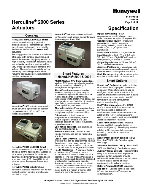
Honeywell Process Control, 512 Virginia Drive, Fort Washington, PA 19034Printed in U.S.A. ν © Copyright 2006-2008 — HoneywellHerculine ® 2000 Series Actuators61-86-03-14June 08Page 1 of 14SpecificationOverviewHoneywell’s HercuLine ® 2000 seriesactuators are low torque, precision electric actuators incorporating all of the easy-to-use, high quality, and reliable features of the traditional HercuLine ® actuators. Ensuring processes operate at maximum efficiency, with minimal downtime, and lowest lifetime cost requires precision and high reliability Herculine ®actuators. They are industrial rated and engineered for very precise positioning of dampers and valves. They perform especially well in extremely demanding environmentsrequiring continuous duty, high reliability, and low maintenance. HercuLine ® 2000 actuators are used inon/off power to open/close or positionproportional with 135 or 1000 ohmfeedback applications.HercuLine ® 2001 and 2002 Smart actuators are used in current proportional or digital control applications. Access to all actuator parameters for real-time business and maintenance decisions isstandard through Modbus RTU, localdisplay, or via HercuLink ® Palm PDAsoftware.HercuLine ® 2002 actuators have additional standard features such as non-contact position sensing and slidewire emulation output. HercuLink ® software enables calibration, configuration, and access to maintenance data using your Palm PDA.Smart Features – HercuLine ® 2001 & 2002 RS485/Modbus RTU Communication -Modbus RTU communication is standard allowing seamless networking of Honeywell control productsAlarm Functions – Alarms may be assigned to relay outputs or may be accessed through the Modbus network. Alarms can be triggered from stall,temperature limits, motor cycle count, out of automatic mode, digital input, position, input failure, position sensor failure,power up failure, and more. Characterization – Programmable linear, equal percentage, quick opening, or user configured 20-point characterizationFailsafe – the actuator can beprogrammed to drive open, closed, remain in-place, or drive to a userspecified position on loss of input signal or position sensor.Split range operation –programmable and infinitely adjustable.Factory Calibration – stored in non-volatile memory and can be restored at any time.Digital Input Override – A digital input is provided that can be programmed to drive the actuator open, closed, remain in-place, or to a user specified position oncontact closure for emergency situations. Health Monitoring – A standard feature on all HercuLine ® Smart actuators accumulates information about actuatoroperation. The information then can be used to evaluate and determine predicted or scheduled maintenance periods. Parameters monitored are accumulated stall time, exceeded thermal operatingrating of the actuator, and number of motor starts in a region of travel, total travel and current actuator travel.Input Filter Setting – Fourprogrammable combinations - none,spike, low pass, or spike + low pass filter.Configuration security – Passwordprotection is provided to prevent tampering, allowing users to lock out some, all, or no groups of setup parameters. Direction of rotation – programmable. Input Signals – 0/4 to 20 mA, 0/1 to 5 Vdc, 0 to 10 Vdc, Digital RS485 Modbus RTU protocol, or Series 90 control. Output Signals – 0/4 to 20 mA, 0/1 to 5 Vdc or slidewire emulation. Accurate Positioning – Motor/gear train provides accurate positioning with almost instantaneous start/stop characteristics. Stall Alarm – provides alarm output in theevent of actuator stall due to overload. Smart OptionsHercuLink ® Software – loaded onto theusers Palm PDA, laptop PC or desktop computer. This software allows you to configure or calibrate the actuator. Inaddition, maintenance information may be read, stored and later loaded in CSV format to the user’s computer for maintenance tracking.Hart ™ Communication – For HART user’s optional HART communications provides access to calibration,configuration, and maintenance data. In addition, the HART communicationsoption is structured to work with the HART Asset Management Features.Local HMI Configuration – Optional keypad and high intensity display isavailable (Figure 1). The display may be rotated in 90° increments for actuator mounting orientations other than horizontal.Non-contact position sensing (NCS) – Herculine ® 2002 only. See description next page.Slidewire Emulation (SEC) – Herculine ®2001 and 2002 only. See text next page.Auxiliary Relay Outputs –Programmable relay outputs can be used in place of auxiliary switch outputs to provideadditional functionality such as indication of alarm status, control of other equipment, or to indicate position. Battery Powered 232/485 converter and cable – used to connect the Palm PDA to the HercuLine ® actuator for communication.61-86-03-14 Page 2Non-Contact Position SensingAvailable in the HercuLine ®2002actuator. The technology is a variableinductance, non-contact position sensor mounted directly to the actuator outputshaft providing precision position sensing from 0 to 150 degrees (Figure 3). Thistechnology eliminates maintenance item such as wipers, bearings, as well asstatic friction, hysteresis and electricalnoise over a wide range of demandingenvironmental conditions. Typically use in very demanding applicati s dons wheredowntime is not an option.Slidewire EmulationAvailable in the HercuLine ® 2001/2002 actuator. The Slidewire EmulationCircuit (SEC) emulates the proportiona voltage output of a typical slidewire through a high impedance circuit. Th voltage output is proportional to the supply voltage and shaft position. If ordered on the 2002 model, a non-contact position sensor is used todetermine shaft position in place o slidewire. Typically used in very demanding applications wher l e f the e downtime is not an option.Potentiometer SensingAn advanced high cycle filmpotentiometer for position sensing for true position feedback is available as option on the Herculine an ndard on Herculine ®2001 EEU model.® 2000 BMUmodel and sta Self-locking/releasingGear TrainThe worm gear output combination is self-locking and self-releasing and maintains position upon loss of power. It is designed to hold greater than two times the rated output torque in a back-driving condition. This design provides superior reliability without themaintenance associated with other self-locking and brake mechanisms. General Features • e thout • ycle – Continuous duty•y out degrading •Hz, single phase <Motor - no burn out motor can b stalled up to 100 hours wi damage to the actuator.Duty C cycle Any position mounting – the actuator may be mounted in an orientation with performance.Power Requirements – Low power consumption 120/240 Vac, 50/60 0.6/0.3 Amp.•X industrial •-•culine ® 2000 series •ification – CSA (pending), UL, CE Enclosure – Rugged, Die cast aluminum NEMA 4grade enclosure.Low Maintenance – Simple proven design means high reliability/low maintenance. Limit Switches – Two end-of-travel electric limit switches are supplied as standard equipment with all Her actuators.• Warranty – Exceptional warranty CertGeneral Options•r PDT switches are •tuator when power is • vailable •s to r ndis & Staefa) •or valve or damper connection.Auxiliary Switches – up to fou additional S available.Manual Operation – a manual hand wheel is optional and used to operate the ac not available.Auto-Manual – electric hand switch with auxiliary contacts indicating an "Out-of-Auto" position is a for local electric control.Competitive Mounting Plates – to adapt the HercuLine ® actuator Invensys (Barber-Colman) o Siemens (La mountings.Linkage assemblies – Pushrod assemblies f61-86-03-14Page 3Optional Local Display and Keypad for HercuLine ® 2001 and 2002A local display and keypad is optional for configuration and set-up (Figure 2). A high intensity 10-character LED display and simple push buttons provide quick access for actuator set up and status information. If relay outputs are specified, all configuration can be done through either the local HMI interface or the HercuLink ® configurator. HercuLink ® Palm PDA software or HART ™ communications is available for those ordering units without the display and keypad.Lower Control Arm RotationPushbuttons (Fou (Six Cha to Access Set Up, Status Calibration Para meters.Figure 1 Local HMI (Display and Keypad)61-86-03-14 Page 4Non-Contact Sensor NCS Spoiler (shown at full150 degree travel CCW)NCS PWA NCS setscrewRelay PWA card guides (relay PWAs removed)Figure 2 Non-Contact Sensor Assembly (HercuLine® 2002)61-86-03-14Page 5HercuLink® Computer InterfaceHercuLink® Computer software enables access to programming and communication functions available as standard with the HercuLine® 2001 and 2002 actuators without the added expense of the keypad & display HMI. Using a Palm™ PDA, laptop PC or desktop computer, HercuLink® software, and a RS232/485 converter users may configure, calibrate, and access maintenance information locally or remotely to the actuator.Using HercuLink® software the computer may be used as a master device over a Modbus network to access information to/from the actuators and to control the device. Set-up configurations may also be stored on the computer for download to other HercuLine®devices. Information may be stored on the users PC in CSV format for use in preventative maintenance programs.•Certified on Palm™ m125, m130, and m505.•Compatible with Palm OS3.5 or higher.•Compatible with Windows 2000 or XP operating systems•Minimum system requirements:•Windows 2000 (w/service pack 2), Windows NT (w/service pack 5), Windows ME, Windows XP•200 MHz Pentium with 64 Megs RamPalm™ is a trademark of Palm, Inc.HotSync® is a registered trademark of Palm Computing, Inc.HercuLink® is a trademark of HoneywellFigure 3 PDA connection61-86-03-14Page 6Set Up/Configuration Parameters for Keypad & Display or HercuLink® SoftwareConfiguration parameters are logically grouped and accessed using the local HMI. Actuator calibration is also accomplished through a simple procedure using the keypad. By pressing the SETUP button on the HMI, you can step through the set up groups that contain all of the configuration parameters. The table below summarizes the configuration parameters available within the various set up groups. Full details of all configuration parameters are found in the HercuLine® 2000 Series Actuator Installation, Operation and Maintenance Manual, document number 62-86-25-10.Set Up Group Configuration Parameter Selections/SettingsSET INPUT⎯Selects various parameters that define actuator operation.IN TYP – Input Actuation TypeINP HI – Input High Range ValueINP LO – Input Low Range ValueFILTYP – Input Filter TypeLPFILT – Low Pass Filter Time ConstantDirect – Actuator RotationDband – Input DeadbandFSFTYPH – FailsafeHI TypeFsFVALH – FailsafeHI ValueFSFTYPL – FailsafeLO TypeFsFVALL – FailsafeLO ValueCHAR – Input Characterization TypeCUST – Custom Characterization TypeSET RELAY⎯When the actuator is equipped with optional relays, this set up group allows you to set relay action for various actuator operating conditions. Contact closure can be wired to external annunciators or alarm points to indicate conditions for any of the Relay Types. RTYPnn – Relay TypeInput RangePosition RangeDeviationUpper or Lower Limit TravelTemperature High or LowCycle CountMotor StalledManual ModePower Up Test FailureInput Signal FailurePosition Sensor Signal FailureDigital Input ClosureTotal Degrees TraveledRnnVAL – Relay ValueRnn HL – Relay High/LowRLYnHY – Relay HysteresisSET CUROUT⎯Selects the current (or voltage) output range of the actuator.CUROUT - Output Signal Range4 – 20 mA 0 – 20 mA1 – 5 V 0 – 5 VOr SWESET COMM⎯Actuator can be defined as a master or slave device on a Modbus RTU RS-485 loop. Operating setpoint can be transmitted to the actuator and operating status can be read when connected to supervisory control M – Communications Parameters ADDRES – Device AddressBAUD – Baud RateXmtDLY – Response DelayDBLBYT – Floating Point Data FormatSET DIGINP⎯Selects digital input action upon contact closure. DIGINP – Digital Input State Endpos – End Position ValueSET DISPLA⎯Selects desired decimal places and engineering units for local display DECMAL – Decimal Point Location EUNITS – Units DisplayUNITS – Display UnitsCAL INPUT, MTR, CURENT⎯If needed, field calibration of the actuator input, motor position and actuator output can be performed using the local keypad and display.61-86-03-14Page 7 Set Up Group Configuration Parameter Selections/SettingsSET LOCK⎯Enables lock out or access to selected set up group parameters and calibration values.LOCKID – Set Security Password LOCK – Lock OutMAENAB – Mode button lockoutREAD STATUS⎯Displays failsafe condition and the results of various diagnostics performed during power up.FAILSF – FailsafeRAMTST – RAM Test DiagnosticSEETST – Serial EEPROM TestDiagnosticCFGTST – Configuration Test DiagnosticCALTST – Calibration Test DiagnosticSET DRVINF⎯Allows access to actuator device information.VERSON – Firmware VersionSPEED – Stroke SpeedPOWER – Power Input Voltage and LineFrequencyTAG – Tag NameDMFG – Manufacturing DateLREP – Date of Last RepairLCAL – Date of Last Field CalibrationREPTYP – Repair TypeSET MAINT⎯Allows access to parameters that monitor operating conditions.TEMP – Actuator TemperatureTEMPHI – High Temperature LimitTEMPLO – Low Temperature LimitACSTA – Accumulated Stall TimeSTARTS – Accumulated Motor StartsRLnCNTS – Relay Cycle CountsREGNn – Accumulated Motor StartsTOTDEG – Total degrees traveledMANRST – Reset Maintenance StatisticsLD CAL – Restore CalibrationLD CFG – Restore ConfigurationSYSRST – System RestartSpecifications – GeneralPhysicalWeight 2000: 25 lb. (11.36 kg)2001,2002: 27 lbs. (12.27 kg)Enclosure Precision-machined die cast aluminum housing, finished in light gray powder coat epoxy. Gear Train Alloy steel, high efficiency steel spur gear primary train. Precision ground, self-locking/selfreleasing worm gear final mesh.Mechanical Stops Factory set at 90° or 150° (+/-5°).Storage Temperature –40 °C to +93 °C (–40 °C to +200 °F)Relative Humidity 0 % to 99 % R.H. non-condensing over the full operating temperature range.Scale 0 % to 100 % corresponding to full crank arm travel.Crank Arm Adjustable radii 1.0 in (25.4mm) to a maximum of 2.8 in (71.1mm). Position adjustablethrough 360° rotation.Output Shaft 0.625+/-.005 in (15.88 +/-.13mm) diameter (round)Rotation 90° or 150° degrees between 0 % and 100 % on scale, limited by mechanical stops. Manual Hand wheel(option)Provides a means of positioning the actuator in the event of a power failure or set-up. Lubrication Texaco Starplex 2 EP GreaseOutput Torque/Full Travel Stroking Time Torque lb-in (N M)50 / (6.0)100 / (11.5)200 / (22.5)400 / (45.0)400 / (45.0)50 Hz (90°/150°)4.5 / 7.59 / 1518 / 3036 / 6054 / 9060 Hz (90°/150°)4 / 67 / 1215/2530/5045/7561-86-03-14Page 8ElectricalMains Supply 100-130 Vac single phase, 50 Hz or 60 Hz200-240 Vac single phase, 50 Hz or 60 HzMotor Instant start/stop, non-coasting, non-burnout, continuous duty, permanent magnet,synchronous induction motor. Can be stalled up to 100 hours without damage.Motor Current = No load = full load = locked rotor = 0.4 amp for 120Vac, 0.2 amp for 240 VacLoss of Power Stays in place on loss of powerLocal Auto/Manual Switch Optional – Allows local and automatic operation of the actuator.End of travel Limit Switches Standard – adjustable to limit actuator travel to less than 90 or 150 degrees respectively Auxiliary Switches/Relays Optional – Up to 4 additional SPDT switches rated at (10 A at 125 Vac, 5 A at 250 Vac). CertificationsApprovals CSA/UL (Standard)CE Compliant (optional)Enclosure Rating Type 4 (NEMA 4), IP66 (standard)Torque Settings of Crank Arm BoltsClamp Bolt 88 lb-in (10 N-m)Electrical and Performance SpecificationsHercuLine® 2000 SeriesHercuLine® 2002 HercuLine® 2001 Herculine® 2000Input Signals Analog:•0/4 to 20 mA (With CPUPWA jumper in currentposition)•0/1 to 5 Vdc•0 to 10 VdcDigital:•Modbus RTU (RS485) Analog:•0/4 to 20 mA (With CPUPWA jumper in currentposition)•0/1 to 5 Vdc•0 to 10 Vdc•Series 90 controlDigital:•Modbus RTU (RS485)120 Vac drive open/120 Vacdrive close240 Vac drive open/240 Vacdrive closeIsolation Input signal, output signal and power are isolated from eachother.NA Load Requirement (4-20) Current Out — 0 to 1000 ohms NAInput Impedance 0/4 to 20 mA0/1 to 5 Vdc0-10 Vdc 250 ohms10 K ohmsNA0 to 20 mA, 4 to 20 mA0 to 5 Vdc & 1 to 5 Vdc with 250 ohm resistor, (0 to 16 Vdc with 800 ohm resistor) Dual output 1000 ohms over 90 degrees (135 ohms with 158 resistor)Dual output 1000 ohms over 150 degrees (135 ohms with 158 resistor)FeedbackSlidewire emulation - Provides output voltage ratiometric toshaft position and potentiometric to supply voltage(1 Vdc to 18 Vdc) without a slidewire. Emulates a 100 ohm to1000 ohm slidewire. 10 mA output maximum.61-86-03-14Page 9HercuLine® 2002 HercuLine® 2001 Herculine® 2000 Communications Modbus RTU or optional HART™NAOperating Temperature –40°C to +75 °C (–40°F to +170 °F) -40°C to +85 °C (-40°F to+185 °F)Position sensing Non-contact position sensor 1000 ohm film potentiometer Optional dual 1000 ohm filmpotentiometersSensitivity 0.2 % to 5 % of 90° span, proportional to deadband NAHysteresis Less than 0.4 % of full scale NADeadband 0.2 % to 5 % of 90° span, programmable. Shipped at 0.5 %NARepeatability 0.2 % of 90° span NARepositions(minimum @ 90 or 150degree stroke)Table 1 option –050- Table 1 option –100- Table 1 option –200- Table 1 option –400- Table 1 option –600- 160290450700900120250400400400500Voltage/ SupplyStability0.25 % of span with +10/–15 % voltage change NATemperature Coefficient Less than ± 0.030 % of span per degree C for 0 °C to 50 °CLess than ± 0.05 % of span per degree C for –40 °C to 75 °CNAZero Suppression 90 % of span.NA Input Filters Selectable spike and low pass filters.NASolid State Motor Control Two triac switches for clockwise or anti-clockwise motoroperation. Transient voltage protection provided.NAFailsafe operation If input signal exceeds configured input range. Selectable andadjustable.NA Direction of Rotation Field programmable Wire swap Duty Cycle ContinuousProgrammableFunctionsSelectable and configurable operating parameters:NA• Inputrange• Inputfiltering• Inputcharacterization• Security•Digital Input action• Deadband•Failsafe on loss of input signal•Failsafe on loss of position sensor•Direction of rotation•Relay closure action• Communicationparameters•Split range operation• Outputrange• Alarms61-86-03-14Page 10Actuator Crank ArmThe HercuLine® 2000 Series Actuators come standard with a 2.8 inch (71.12mm) crank arm (Figure 4). The crank arm uses linkage kits (above). Adjustable radius (1.0 in (25.4mm) to 2.80 in (71.12mm)). Position adjustable through 360° rotation.Figure 4 Standard 2.8” (71.12mm) Crank ArmFigure 5 Crank Arm with optional ball joint and push rodModel Selection GuidecontinuedOutline Dimension DrawingsmminchesActionator M640A, M740A, and M940A replacementSee Honeywell SalesNet at /salesnet/supporting_docs/sales_tools/actionator_to_hl_xover.xlsWarranty/RemedyHoneywell warrants goods of its manufacture as being free of defective materials and faulty workmanship. Contact your local sales office for warranty information. If warranted goods are returned to Honeywell during the period ofcoverage, Honeywell will repair or replace without charge those items it finds defective. The foregoing is Buyer's sole remedy and is in lieu of all other warranties, expressed or implied, including those of merchantability andfitness for a particular purpose. Specifications may change without notice. The information we supply is believed to be accurate and reliable as of this printing. However, we assume no responsibility for its use.While we provide application assistance personally, through our literature and the Honeywell web site, it is up to the customer to determine the suitability of the product in the application.For more information, contact Honeywell sales at (800) 343-0228.Honeywell Process ControlHoneywell512 Virginia DriveFort Washington, PA 1903461-86-03-14 June 08 Printed in USA /ps。
Series 190 Displacer Type液位控制设备规格与安装使用说明书

Series 190 Displacer Type Liquid Level ControlsSpecifications - Installation and Operating InstructionsBulletin O-532OPERATING CHARACTERISTICSThe displacers are suspended on a cable from the armature of a magnetic head control with a spring partially supporting their weight. As the displacers become submerged in a rising liquid, their weight decreases, allowing the spring to move the cable and armature upward, thereby actuating the mercury switches or snap action switches. The displacers are secured on the cable by clamps. Operating levels can be adjusted by loosening the clamps and moving the displacers up or down the cable as required. The buoyancy produced by the submerging of one displacer is not sufficient to allow the spring to raise the armature*; a second displacer must be partially submerged before any operation occurs on a rise. On a drop, however, the cable will not move to its full down position until the level falls to approximately the mid point of the lowest displacer. By spacing the displacers and calibrating the spring, adjustable level operation and various stage operations can be provided.*Exception - Typer 195-4: Lower stage operates on and off as liquid level move within length of lower displacer.Typer A-190 operates on and off as liquid level moves within length of a singledisplacer.Construction - all types. Standard displacers are porcelain (also available of other materials). Stops 316SS. Cable (10 ft) 316 stainless steel (longer lengths available). All enclosures equipped with 3/4˝ NPT conduit connection. Terminal block for electrical connections. Stand flange: 4˝ 125# C1 - other sizes and materials available. INSTALLATION INSTRUCTIONSMOUNTINGAll types must be mounted with switch mechanism in a level position. Flange must be positioned so that control is mounted level.Check for obstructions in tank or vessel - be sure that no rods, projections or other obstacles interfere with free operations of the displacers.No guides are necessary unless excessive turbulence occurs, in which case, a guide pipe could be used. The inner diameter of the pipe or tube should be at least one half to one inch larger than the diameter of the displacers and should have a vent above the high level of he liquid - bottom end to be open. PROCEDURE FOR INSTALLING CONTROL HEAD AND DISPLACERSNote: Do not tamper with setting of spring assembly. It has been factory set for the specific gravity specified on your order.Disassemble equipment as follows:a. Remove spring clip located near bottom end of the threaded connectionprotruding from control case. Pull out on spring clip which releases armature rod, and spring assembly.b. Insert control head thru flange and tighten securely by means of the treadedconnection. Use a wrench only on the hex surface under control base.c. Reassemble armature rod with spring assembly into bottom opening of thethreaded pipe connection and secure with spring clip. Note: On two stage models be sure washer is inside tube before inserting spring clip. To facilitate insertion of washer and spring clip turn control upside down on a firm surface.d. Attach cable and displacers to armature by means of the threaded clampattached to the cable.e. Insert complete assembly and flange into the tank or vessel and fasten flange. WIRINGWire in accordance with local electrical codes or follow equipment manufacturers instructions.CAUTION: Do not loosen or move switch mechanisms or control adjustment will be altered. Do not tamper with switch wires. Position of these wires is essential to proper operation. Tampering with these wires will void warranty.3/4˝ NPTSPRING ASSEMBLY(FACTORY SET) By DwyerSINGLE STAGE OPERATIONSingle stage controls will operate at any specific gravity and temperature listed intables with standard factory setting.Series A190 - Single Stage - Fixed DifferentialsSeries B190 - Single Stage - Adjustable DifferentialsMinimum differential (c) can be reduced, approximately 1˝ by removing the cable clamp from between the displacers and turning the lowerdisplacer so the flat side is up. If a narrower differential is needed, use a Type A190 control.SINGLE STAGE CIRCUIT SPECIFICATIONS AND ELEC. RATINGMERCURY SWITCH TYPESAC or DC10 amp. 120 volts, 5 amp. 240 voltsAvailable 440 volts 3 amp. A.C.ENCLOSED METAL CONTACT SNAP-ACTION SWITCHES12 Amp. 120 volts; 5 Amp. 240 volts AC.1/2 hp. 120/240 volts ACD.C. 0.5 Amp. 125 volts; 0.25 Amp. 250 voltsCIRCUITSSINGLE STAGESpec. No. 7810 (1) SP-DT SwitchSpec. No 7806 (2) SP-DT SwitchesTWO STAGE OPERATIONAll two stage types are factory set for a given specific gravity and temperature for each application.Series 195-4 - Two Stage - Fixed Differentials Adjustable Spread Between StagesMinimum Specific Gravity 0-9 - Maximum Temperature 200°On specific gravities below .95 control is not recommended where temperatures vary appreciably.Series 195-6 - Two Stage - Adjustable Differential Each StageHigh trip point for lower stage common with low trip point for upper stageMinimum Specific Gravity 0.5 - Maximum Temperature 200°Series 195-7 - Two Stage - Adjustable Differential Each Stage Common trip point at LOW levelSeries 195-8 - Two Stage - Adjustable Differential Each Stage Common trip point at HIGH levelPrinted in U.S.A. 4/18FR# 441865-00 Rev. 1©Copyright 2018 Dwyer Instruments, Inc.Specific gravity should not vary more than ±.1 from factory setting. Temperature should not vary more than ±50°F from factory setting.Note: Single stage displacer controls will tolerate much wider fluctuations of specific gravity and temperature as indicated in tables.TWO STAGE CIRCUIT SPECIFICATIONS AND ELEC. RATING Mercury Switch types AC or DC10 Amp. 120 volts 5 Amp. 240 volts 4 Amp. - No. 48102 Amp. - No 4810ENCLOSED METAL CONTACT SNAP-ACTION SWITCHES 12 Amp. 120 volts; 5 Amp. 240 volts AC.1/2 hp. 120/240 volts ACD.C. 0.5 Amp. 125 volts; 0.25 Amp. 250 volts CIRCUITSSpec. No. 7806 (2 SP-DT each stage)Spec. No. 7810 (SP-DT each stage)。
英飞凌汽车电子器件选型

Lowbeam Indicator Park Optional Fog
55W
27W 10W 2x 55W
Park Indicator Lowbeam Highbeam
10W 27W 55W
65W
Highbeam 65W
Lowbeam 55W
Indicator 27W
Left Front-Light
Control
Right Front-Light
Control
LEDs
Relays
m n
Low-Side Driver
HITFET ™ BTS3110/18
BTS3134 BTS3160D
Interior Light
LED Driver
Basic LED Driver without Status
BCR40x
Basic LED Driver TLE424x
Power System ICs
C Smart Power C System Integration
– ABS/Airbag – Powertrain – Body
Infineon® Embedded Power ICs
C Single Package C Smart Power and
Controller Integration
System Basis Chip TLE826xE TLE826x-2E
Optional: DC/DC Regulator
TLF50281
Single or Dual High-Side Driver
Supply
Communication
32-bit Multicore/Lockstep
- 1、下载文档前请自行甄别文档内容的完整性,平台不提供额外的编辑、内容补充、找答案等附加服务。
- 2、"仅部分预览"的文档,不可在线预览部分如存在完整性等问题,可反馈申请退款(可完整预览的文档不适用该条件!)。
- 3、如文档侵犯您的权益,请联系客服反馈,我们会尽快为您处理(人工客服工作时间:9:00-18:30)。
19.0 inches (481.9mm) diagonal 396.0(H) x 324.0(V) x 15.5(D) mm(Typ.) 0.098*RGB(H)mm x 0.294(V)mm 1280 horizontal By 1024 vertical Pixels. RGB stripe arrangement LVDS 2Port 16.7M colors 300 cd/m2 ( Center 1Point, typ) R/L 160(Typ.), U/D 160(Typ.) Total 24.03 Watt(Typ.), (3.43 W@VLCD , 20.6 W@[Lamp=7.5mA]) 1950g (Typ.) Transmissive mode, normally White Hard coating (3H), Anti-glare treatment of the front polarizer
G1024
+5V
VLCD
Power Circuit Block
CN2, 3 (2pin) CN4, 5 (2pin)
Back light Assembly (4CCFL)
General Features
Active screen size Outline Dimension Pixel Pitch Pixel Format Interface Color depth Luminance, white Viewing Angle (CR>10) Power Consumption Weight Display operating mode Surface treatments
SIGNATURE
DATE
APPROVED BY K.G. Park / G.Manager
DATE
/
REVIEWED BY S.J. So / Manager [C]
/
S.Y. An / Manager [M] H.S. Lee / Manager [P]
/
PREPARED BY H.S. Kim / Engineer Product Engineering Dept. LG. Philips LCD Co., Ltd
LM190E08 Liquid Crystal Display
Product Specification
SPECIFICATION FOR APPROVAL
(◆) Preliminary Specification ( ) Final Specification
Title
BUYER MODEL General
19.0” SXGA TFT LCD
SUPPLIER *MODEL SUFFIX LG.Philips LCD CO., Ltd. LM190E08 TLL2
*When you obtain standard approval, please use the above model name without suffix
Contents
No
COVER CONTENTS RECORD OF REVISIONS 1 2 3 1) 2) 3) 4) 5) 6) 7) 4 5 6 7 1) 2) 8 1) 2) 9 1) 2) 3) 4) 5) 6) GENERAL DESCRIPTION ABSOLUTE MAXIMUM RATINGS ELECTRICAL SPECIFICATIONS ELECTRICAL CHARACTERISTICS INTERFACE CONNECTIONS SIGNAL TIMING SPECIFICATIONS SIGNAL TIMING WAVEFORMS COLOR INPUT DATA REFERNECE POWER SEQUENCE POWER DIP CONDITION OPTICAL SFECIFICATIONS MECHANICAL CHARACTERISTICS RELIABILITY INTERNATIONAL STANDARDS SAFETY EMC PACKING DESIGNATION OF LOT MARK PACKING FORM PRECAUTIONS MOUNTING PRECAUTIONS OPERATING PRECAUTIONS ELECTROSTATIC DISCHARGE CONTROL PRECAUTIONS FOR STRONG LIGHT EXPOSURE STROAGE HANDLING PRECAUTIONS FOR PROTECTION FILM
Record of Revisions
Revision No
Ver 0.1
Date
Mar. 08, 2007
Page
Description
First Draft, Preliminary Specifications
Ver. 0.1
90E08 Liquid Crystal Display
Product Specification
1. General Description
LM190E08-TLL2 is a Color Active Matrix Liquid Crystal Display with an integral Cold Cathode Fluorescent Lamp(CCFL) backlight system. The matrix employs a-Si Thin Film Transistor as the active element. It is a transmissive type display operating in the normally white mode. It has a 19.0 inch diagonally measured active display area with SXGA resolution (1024 vertical by 1280 horizontal pixel array) Each pixel is divided into Red, Green and Blue sub-pixels or dots which are arranged in vertical stripes. Gray scale or the brightness of the sub-pixel color is determined with a 8-bit gray scale signal for each dot, thus, presenting a palette of more than 16,7M colors with Advanced-FRC(Frame Rate Control). It has been designed to apply the interface method that enables low power, high speed, low EMI. FPD Link or compatible must be used as a LVDS(Low Voltage Differential Signaling) chip. It is intended to support applications where thin thickness, wide viewing angle, low power are critical factors and graphic displays are important. In combination with the vertical arrangement of the sub-pixels, the LM190E08-TLL2 characteristics provide an excellent flat panel display for office automation products such as monitors. FIG. 1 Block Diagram
RGB
Source Driver Circuit
S1 S1280 G1
LVDS
pair #1
(30pin)
Gate Driver Circuit
CN1
LVDS
pair #2
Timing Controller &LVDS 1 Chip
TFT - LCD Panel
(1280 × RGB × 1024 pixels)
Mar. 08, 2007 4 / 29
LM190E08 Liquid Crystal Display
Product Specification
2. Absolute Maximum Ratings
The following are maximum values which, if exceeded, may cause faulty operation or damage to the unit. Table 1. Absolute Maximum Ratings Parameter Power Supply Input Voltage Operating Temperature Storage Temperature Operating Ambient Humidity Storage Humidity Symbol VLCD TOP TST HOP HST Values Min -0.3 0 -20 10 10 Max +5.5 50 60 90 90 Units Vdc °C °C %RH %RH 1 Notes At 25℃
Note : 1. Temperature and relative humidity range are shown in the figure below. Wet bulb temperature should be 39 °C Max, and no condensation of water. FIG. 2 Temperature and Relative Humidity