Modeling and Simulating Extreme Collaboration An Agent-Based Approach
把课堂搬上舞台的作文英语

When it comes to bringing the classroom to the stage,the idea is to create an educational experience that is both engaging and entertaining.Here are some key elements to consider when crafting an essay on this topic:1.Setting the Scene:Begin by describing the transformation of a traditional classroom setting into a stage.Discuss the physical changes,such as the arrangement of desks,the use of props,and the lighting to set the mood for learning.2.Role of the Teacher:The teachers role shifts from being the sole disseminator of knowledge to a director and facilitator.Discuss how the teacher guides the students through the learning process,encouraging them to take on roles and responsibilities that are typically reserved for the teacher.3.Student Participation:Highlight the importance of active student involvement. Students become actors in their own learning,taking on roles that require them to explore, question,and present information in a way that is both educational and theatrical.4.Curriculum Integration:Explain how the curriculum is adapted to fit the stage format. This could include turning historical events into plays,scientific concepts into demonstrations,or mathematical problems into interactive games.5.Learning Outcomes:Discuss the potential benefits of this approach,such as increased student engagement,deeper understanding of concepts,and the development of communication and presentation skills.6.Challenges and Solutions:Address the potential challenges of implementing such a system,such as logistical issues,the need for additional resources,and the potential for uneven student participation.Offer solutions or strategies to overcome these obstacles.7.Case Studies or Examples:If possible,provide reallife examples or case studies of educational institutions that have successfully implemented this approach.Discuss the outcomes and lessons learned from these experiences.8.Conclusion:Conclude by summarizing the main points and emphasizing the potential of this innovative approach to education.Encourage further exploration and experimentation in educational practices to enhance learning experiences.9.Reflection:Reflect on the personal impact of such an educational method.How might it change the way students perceive learning,and how could it influence their future educational and career paths?10.Call to Action:End with a call to action,urging educators,policymakers,and students to consider the benefits of integrating performance and education,and to explore ways to make this a more common practice in schools.Remember to use a variety of sources to support your arguments,including educational research,personal anecdotes,and expert opinions.This will lend credibility to your essay and provide a wellrounded perspective on the topic.。
AWG5000系列混合信号伪随机波形生成器说明书
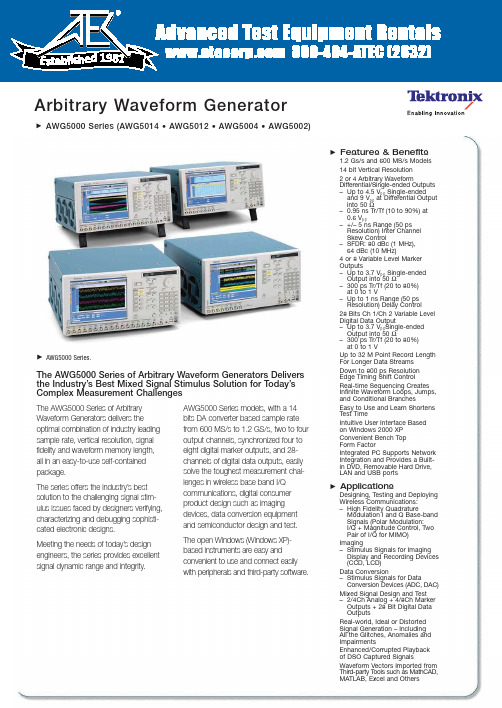
Arbitrary Waveform GeneratorAWG5000 Series (AWG5014 • AWG5012 • AWG5004 • AWG5002)The AWG5000 Series of Arbitrary Waveform Generators Delivers the Industry’s Best Mixed Signal Stimulus Solution for Today’s Complex Measurement ChallengesThe AWG5000 Series of Arbitrary Waveform Generators delivers theoptimal combination of industry leading sample rate, vertical resolution, signal fidelity and waveform memory length,all in an easy-to-use self-contained package.The series offers the industry’s best solution to the challenging signal stim-ulus issues faced by designers verifying,characterizing and debugging sophisti-cated electronic designs.Meeting the needs of today’s design engineers, the series provides excellent signal dynamic range and integrity.AWG5000 Series models, with a 14bits DA converter based sample rate from 600MS/s to 1.2GS/s, two to four output channels, synchronized four to eight digital marker outputs, and 28-channels of digital data outputs, easily solve the toughest measurement chal-lenges in wireless base band I/Q communications, digital consumer product design such as imaging devices, data conversion equipment and semiconductor design and test. The open Windows (Windows XP)-based instruments are easy and convenient to use and connect easily with peripherals and third-party software.AWG5000 Series.Features & Benefits1.2Gs/s and 600MS/s Models 14 bit Vertical Resolution 2 or 4Arbitrary WaveformDifferential/Single-ended Outputs –Up to 4.5V p-p Single-ended and 9V p-p at Differential Output into 50Ω–0.95ns Tr/Tf (10 to 90%) at 0.6V p-p–+/– 5ns Range (50ps Resolution) Inter Channel Skew Control–SFDR: 80dBc (1MHz),64dBc (10MHz)4 or 8Variable Level Marker Outputs–Up to 3.7V p-p Single-ended Output into 50Ω–300ps Tr/Tf (20 to 80%)at 0 to 1V–Up to 1ns Range (50ps Resolution) Delay Control28 Bits Ch 1/Ch 2Variable Level Digital Data Output–Up to 3.7V p-p Single-ended Output into 50Ω–300ps Tr/Tf (20 to 80%)at 0 to 1VUp to 32M Point Record Length For Longer Data Streams Down to 800ps Resolution Edge Timing Shift Control Real-time Sequencing Creates Infinite Waveform Loops, Jumps,and Conditional BranchesEasy to Use and Learn Shortens Test TimeIntuitive User Interface Based on Windows 2000 XP Convenient Bench Top Form FactorIntegrated PC Supports Network Integration and Provides a Built-in DVD, Removable Hard Drive,LAN and USB portsApplicationsDesigning, Testing and Deploying Wireless Communications: –High Fidelity QuadratureModulation I and Q Base-band Signals (Polar Modulation:I/Q + Magnitude Control, Two Pair of I/Q for MIMO)Imaging–Stimulus Signals for Imaging Display and Recording Devices (CCD, LCD)Data Conversion–Stimulus Signals for DataConversion Devices (ADC, DAC)Mixed Signal Design and Test –2/4Ch Analog + 4/8Ch Marker Outputs + 28 Bit Digital Data OutputsReal-world, Ideal or Distorted Signal Generation – Including All the Glitches, Anomalies and ImpairmentsEnhanced/Corrupted Playback of DSO Captured SignalsWaveform Vectors Imported from Third-party T ools such as MathCAD,MATLAB, Excel and OthersArbitrary Waveform GeneratorAWG5000 Series (AWG5014 • AWG5012 • AWG5004 • AWG5002)AWG5000 Series • /signal_sources2EVM/Constellation measurement.Typical Signal Injection.Arbitrary Waveform GeneratorAWG5000 Series (AWG5014 • AWG5012 • AWG5004 • AWG5002) RTSA Spectrum view.9-PAM with 250 Mbps.Mixed signal test by TDS/TLA iView.™AWG5000 Series • /signal_sources3Arbitrary Waveform GeneratorAWG5000 Series (AWG5014 • AWG5012 • AWG5004 • AWG5002)4AWG5000 Series • /signal_sourcesArbitrary Waveform GeneratorAWG5000 Series (AWG5014 • AWG5012 • AWG5004 • AWG5002)AWG5014AWG5012AWG5004AWG5002Arbitrary WaveformsWaveform Length 1 to 16,200,000 points (or 1 to 32,400,000 points,option 01)Number of Waveforms 1 to 16,000Sequence Length 1 to 4,000stepsSequence Repeat Counter 1 to 65,536 or infiniteSequence Control Repeat count,Trigger,Go-to-N and JumpJump Mode Synchronous and AsynchronousRun ModesContinuous Waveform is iteratively output.If a sequence is defined,the sequence order and repeat functions are appliedTriggered Waveform is output only once when an external,internal,GPIB,LAN or manual trigger is receivedGated Waveform begins output when gate is true and resets to beginning when falseSequence Waveform is output as defined by the sequenceClock GeneratorSampling Frequency10 MS/s to 1.2GS/s10 MS/s to 600 MS/sResolution8digitsInternal ClockAccuracy Within ±(1 ppm + Aging),Aging:within ±1 ppm/yearClock Phase Noise Less than –90dBc/Hz at 100kHz offsetInternal Trigger GeneratorInternal Trigger RateRange 1.0μs to 10.0sResolution3digits,0.1μs minimumSkew Control Between OutputsRange– 5 ns to + 5nsResolution5psAWG5000 Series • /signal_sources5Arbitrary Waveform GeneratorAWG5000 Series (AWG5014 • AWG5012 • AWG5004 • AWG5002)AWG5000 Series • /signal_sources6AWG5014AWG5012AWG5004AWG5002Main Arbitrary Waveform Output Resolution14 bitsAnalog OutputOutput StyleDifferential Output Impedance 50ΩConnectorBNC FrontAmplitude Output Voltage Normal:–4.5 V to + 4.5V,Direct –0.3V to +0.3V Amplitude Normal:20mV p-p to 4.5V p-p ,Direct; 20mV p-p to 0.6V p-pResolution 1mVDC Accuracy±(2.0% of Amplitude + 2mV) at offset = 0V Offset (into 50Ω) Range Normal:–2.25V to +2.25V,Direct:N/A Resolution 1mVAccuracy±(2% of offset +10mV at minimum amplitudePulse Response Rise/Fall time:(10% to 90%).Normal:1.4ns (2.0V p-p ),Direct:0.95ns (0.6V p-p )Bandwidth (–3dB)Normal:250MHz (2.0V p-p ),Direct:370MHz (0.6V p-p )Ringing Normal:750mV p-p (4.5V p-p filter through),80mV p-p (2.0V p-p filter through),Direct:60mV p-p (0.6V p-p )Low Pass Filter High range:100MHz,20MHz,Low range:through,100MHz,20MHz,Direct:N/ADelay from Marker Normal:17.5ns to 19.4ns (20MHz filter),3.8ns to 5.7ns (100MHz filter),0 to 1.9ns (Through),Direct:–1.5ns to 0.4nsSine Wave Characteristics (1.2GS/s clock,32 waveform points,37.5MHz signal frequency)(600MS/s clock,32 waveform points,18.75MHz signal frequency)Harmonics Normal:≤–40dBc (2.0V p-p ),Direct ≤=–49dBc (0.6V p-p )Normal:≤–46dBc (2.0V p-p ),Direct ≤=–55dBc (0.6V p-p )Non Harmonics Normal:≤–60dBc (2.0V p-p ,DC to 600MHz)Normal:≤–60dBc (2.0V p-p ,DC to 300MHz)Phase noise ≤–85dBc/Hz (2.0V p-p ,10kHz offset) –85dBc/Hz (2.0V p-p ,10kHz offset) SFDR 50dBc (Normal,37.5MHz,1.2GS/s,2.0V p-p )56dBc (Normal,18.75MHz,600MS/s,2.0V p-p )60dBc (Normal,10MHz,600MS/s,1.0V p-p )60dBc (Normal,10MHz,600MS/s,1.0V p-p )80dBc (Normal,1MHz,600MS/s,1.0V p-p )80dBc (Normal,1MHz,600MS/s,1.0V p-p )64dBc (Direct,10MHz,600 MS/s,0.6V p-p )64dBc (Direct,10MHz,600MS/s,0.6V p-p )80dBc (Direct,1MHz,600 MS/s,0.6V p-p )80dBc (Direct,1MHz,600MS/s,0.6V p-p )Arbitrary Waveform GeneratorAWG5000 Series (AWG5014 • AWG5012 • AWG5004 • AWG5002) Auxiliary OutputsOutput Style Single-endedOutput Impedance50ΩConnector BNC FrontLevel (into 50Ω)(Twice for Hi_Z input)Output Windows–1.00 V to + 2.7VAmplitude0.10 Vp-p to 3.7 Vp-pResolution10mVDC Accuracy±(10% of setting +120mV) Maximum Output Current±54mA /chRise/Fall Time (20% to 80%)300 ps(1.0 Vp-p,Hi +1.0V,Lo 0V) Skew Adjust Between MarkersRange0 to 1000ps Resolution50psRandom Jitter (Typical)1010 clock patternRMS5psrmsTotal Jitter (Typical)2^15–1PN data patternPeak to Peak (p-p)80psp-pClock (VCO) OutRange600MHz to 1.2GHzAmplitude0.4 Vp-pinto 50Ωto GND Impedance:50Ω,AC coupling Connector BNC Rear10MHz Reference OutAmplitude 1.2 Vp-p into 50Ω.Max 2.5 Vp-popenImpedance50Ω,AC couplingConnector BNC RearDC OutputsNumber of Outputs4:independently controlled outputsRange–3.0 to +5.0VResolution10mVMax.Current±100mAConnector2x4 pin header on front panelAWG5000 Series • /signal_sources7Arbitrary Waveform GeneratorAWG5000 Series (AWG5014 • AWG5012 • AWG5004 • AWG5002)AWG5000 Series • /signal_sources8Trigger In Impedance 1 k Ωor 50ΩPolarity POS or NEG ConnectorBNC FrontInput Voltage Range1 k Ω:±10V.50 Ω:±5V Threshold Level –5.0 V to 5.0VResolution 0.1VTrigger Jitter2.0ns to 4.5ns (Typical) Trigger Mode Minimum Pulse Width 20nsTrigger Hold-off 832* sampling_period – 100ns Delay to Analog Out128* sampling_period + 250ns Gate Mode Minimum Pulse Width 1024* sampling_period + 10ns Delay to Analog Out640* sampling_period + 260ns Event Input Impedance 1 k Ωor 50ΩPolarity POS or NEG ConnectorBNC FrontInput Voltage Range 1 k Ω:±10V.50 Ω:±5V Threshold –5.0 V to 5.0VResolution0.1VSequence Mode Mode Minimum Pulse Width 20nsEvent Hold Off 1024* Sampling Period + 10nsDelay to Analog Out640* Sampling Period + 280 ns (Jump timing:Asynchronous jump)External Clock IN Input Voltage Range 0.2 V p-p to 0.8 V p-p Impedance50Ω,AC coupledConnectorBNC RearReference Clock IN Input Voltage Range 0.2 V p-p to 3.0 V p-p Impedance50Ω,AC coupledFrequency Range 10MHz,20MHz,100MHz (with ±0.1%)ConnectorBNC RearPhase Lock IN Input Ranges5MHz to 600MHz (acceptable frequency drift is ±0.5%)Input Voltage Range 0.2 V p-p to 3 V p-pConnectorBNC RearAdd IN For each analog channel Impedance 50Ω,DC coupledDC Gain 1BandwidthDC to 100MHz at –3 dBInput Voltage Range ±1.0V ConnectorBNC RearArbitrary Waveform GeneratorAWG5000 Series (AWG5014 • AWG5012 • AWG5004 • AWG5002)(Third party software creation waveform data:MATLAB,MathCad,Excel)S/W driver for 3rd party S/W IVI-com driver and MATLAB libraryInstrument Control/Data Transfer PortsGPIB Remote control and data transfer.(Conforms to IEEE-Std 488.1,compatible with IEEE 488.2 and SCPI-1999.0)Ethernet (10/100/1000Base-T)Remote control and data transfer.(Conforms to IEEE 802.3).RJ-45Computer System & Peripherals Windows XP Professional,512 MB SDRAM,80 GB removable Hard Drive at rear (available front mount kit),CD-RW/DVD drive at front,included USB compact keyboard and mousePC I/O Ports USB 2.0 compliant ports (6 total,2 front,4 rear),PS/2mouse and keyboard connectors (rear panel),RJ-45 Ethernet connector (rear panel) supports 10/100/1000BASE-T,XGA outDisplay Characteristics10.4inch,LCD color display with touch screen,1024 (H)x768 (V) (XGA)Power Supply100 to 240VAC,47 to 63HzPower Consumption450WSafety UL61010-1,CAN/CSA-22.2,No.61010-1-04,EN61010-1,IEC61010-1Emissions EN 55011 (Class A),IEC61000-3-2,IEC61000-3-3Immunity IEC61326,IEC61000-4-2/3/4/5/6/8/11Regional CertificationsEurope EN61326Australia/New Zealand AS/NZS 2064AWG5000 Series • /signal_sources9Arbitrary Waveform GeneratorAWG5000 Series (AWG5014 • AWG5012 • AWG5004 • AWG5002)Ordering Information Arbitrary WaveformGenerator MainframeAWG50141.2GS/s,4-channel,14bits,16M point/channel Arbitrary Waveform Generator.AWG50121.2GS/s,2-channel,14bits,16M point/channel Arbitrary Waveform Generator.AWG5004600MS/s,4-channel,14bits,16M point/channel Arbitrary Waveform Generator.AWG5002600MS/s,2-channel,14bits,16M point/channel Arbitrary Waveform Generator.All Models Include:Accessory pouch,front cover, USB mouse,compact USB key board,lead set for DC output,stylus for touch screen 2 each, Windows®XP operating system restore DVD and instructions,AWG5000 Series product software CD and instructions,Document CD with Browser,Quick Start User Manual,registration card,Certificate of Calibration,power cable.Note:Please specify power cord and language option when ordering.Instrument OptionsAWG5014/AWG5012,AWG5004/AWG5002Opt.01 – Waveform Length Expansion (from 16 M to 32 M).AWG5012/AWG5002Opt. 03 –28 bits digital data outputs (digital data of ch 1 and ch 2).Common OptionsInternational Power PlugsOpt. A0 – North America power.Opt. A1 –Universal EURO power.Opt. A2 – United Kingdom power.Opt. A3 – Australia power.Opt. A5 – Switzerland power.Opt.A6 –Japan power.Opt.A10 – China power.Opt.A99 – No power cord or AC adapter.Language OptionsOpt. L0 – English.Opt. L5 – Japanese.Opt. L7 –Simplified Chinese.Opt. L8 – Traditional Chinese.ServiceOpt. CA1 – A single calibration event.Opt. C3 – Calibration service 3 years.Opt. C5 – Calibration service 5 years.Opt. D1 –Calibration data report.Opt. D3 – Calibration data report 3 years (withoption C3).Opt. D5 – Calibration data report 5 years (withoption C5).Opt. R3 –Repair service 3 years.Opt. R5 –Repair service 5 years.Post-sales Service Options:(e.g.,AWG5012-CA1).CA1 – A single calibration event.R3DW – Repair service coverage 3 years.R5DW – Repair service coverage 5 years.R2PW –Repair service coverage 2 yearspost warranty.R1PW –Repair service coverage 1 yearpost warranty.Product UpgradeAWG5014, AWG50UPOpt.M14 – Waveform Length Expansionfrom 16 M point to 32 M point.Product UpgradeAWG5012, AWG50UPOpt. M12 – Waveform Length Expansionfrom 16 M point to 32 M point.Opt.D13 –Digital Data Outputs.Product UpgradeAWG5004, AWG50UPOpt. M04 – Waveform Length Expansionfrom 16 M point to 32 M point.Product UpgradeAWG5002, AWG50UPOpt.M02 – Waveform Length Expansionfrom 16 M point to 32 M point.Opt.D03 –Digital Data Outputs.AWG5000 Series • /signal_sources 10Arbitrary Waveform GeneratorAWG5000 Series (AWG5014 • AWG5012 • AWG5004 • AWG5002)WarrantyOne-year parts and labor.AWG5000 Series • /signal_sources11Arbitrary Waveform GeneratorAWG5000 Series (AWG5014 • AWG5012 • AWG5004 • AWG5002)For Further InformationTektronix maintains a comprehensive, constantly expanding collection of application notes, technical briefs and other resources to help engineers working on the cutting edge of technology. Please visit Copyright © 2008, Tektronix. All rights reserved. Tektronix products are covered by U.S. and foreign patents, issued and pending. Information in this publication supersedes that in all previously published material.Specification and price change privileges reserved. TEKTRONIX and TEK are registered trademarks of Tektronix, Inc. All other trade names referenced are the service marks, trademarks or registered trademarks of their respective companies. 07/08 JS/WOW 76W-20381-3Contact Tektronix:ASEAN/Australasia (65) 6356 3900Austria +41 52 675 3777Balkans, Israel, South Africa and other ISE Countries +41 52 675 3777Belgium 07 81 60166Brazil & South America (11) 40669400Canada 1 (800) 661-5625Central East Europe, Ukraine and the Baltics +41 52 675 3777Central Europe & Greece +41 52 675 3777Denmark +45 80 88 1401Finland +41 52 675 3777France +33 (0) 1 69 86 81 81Germany +49 (221) 94 77 400Hong Kong (852) 2585-6688India (91) 80-22275577Italy +39 (02) 25086 1Japan 81 (3) 6714-3010Luxembourg +44 (0) 1344 392400Mexico, Central America & Caribbean 52 (55) 5424700Middle East, Asia and North Africa +41 52 675 3777The Netherlands ***********Norway 800 16098People’s Republic of China 86 (10) 6235 1230Poland +41 52 675 3777Portugal 80 08 12370Republic of Korea 82 (2) 6917-5000Russia & CIS +7 (495) 7484900South Africa +27 11 206 8360Spain (+34) 901 988 054Sweden 020 08 80371Switzerland +41 52 675 3777Taiwan 886 (2) 2722-9622United Kingdom & Eire +44 (0) 1344 392400USA 1 (800) 426-2200For other areas contact Tektronix, Inc. at: 1 (503) 627-7111Updated 12 November 2007roduct(s) are manufactured in ISO registered facilitie Product(s) complies with IEEE Standard 488.1-1987,RS-232-C,and with Tektronix Standard Codes and Formats.。
集成电路与先进制造本科生科考与科研训练项目 英文

集成电路与先进制造本科生科考与科研训练项目英文Integrated Circuits and Advanced Manufacturing Undergraduate Research and Training ProgramThe field of integrated circuits (ICs) has been a driving force behind the rapid technological advancements that have transformed our world in the past few decades. From the ubiquitous smartphones we carry in our pockets to the powerful computers that power modern industries, ICs have played a crucial role in shaping the landscape of modern electronics. As an undergraduate student interested in this dynamic field, I am excited to participate in the Integrated Circuits and Advanced Manufacturing Undergraduate Research and Training Program, which promises to provide me with a comprehensive understanding of the latest developments in IC design and manufacturing.This program offers a unique opportunity to delve into the cutting-edge research and practical applications of integrated circuits. Through a combination of rigorous coursework, hands-on laboratory sessions, and collaborative research projects, I will gain a deepunderstanding of the principles underlying IC design and fabrication. The curriculum will cover a wide range of topics, including semiconductor physics, digital and analog circuit design, computer-aided design (CAD) tools, and advanced manufacturing techniques.One of the key aspects of this program is the emphasis on hands-on learning and practical application. I will have the chance to work with state-of-the-art equipment and tools used in the industry, such as semiconductor process simulators, layout editors, and testing equipment. This hands-on experience will allow me to translate the theoretical knowledge gained in the classroom into real-world problem-solving skills, preparing me for a career in the dynamic field of integrated circuits.Moreover, the program's research component will provide me with the opportunity to collaborate with faculty members and fellow students on projects that push the boundaries of IC technology. I will be exposed to the latest research trends and challenges in areas such as high-performance computing, energy-efficient electronics, and emerging device technologies. Through this collaborative research, I will develop critical thinking, problem-solving, and communication skills that are essential for success in the field of integrated circuits.In addition to the technical aspects of the program, I am also excited about the opportunity to engage with industry professionals andparticipate in networking events. These interactions will give me a deeper understanding of the real-world challenges and opportunities in the IC industry, and will help me establish valuable connections that can aid in my future career development.As I embark on this journey, I am confident that the Integrated Circuits and Advanced Manufacturing Undergraduate Research and Training Program will provide me with a solid foundation in the field of integrated circuits. By immersing myself in cutting-edge research, hands-on learning, and industry engagement, I will be well-equipped to contribute to the ongoing evolution of this dynamic field. The knowledge and skills I acquire through this program will not only prepare me for a successful career in integrated circuits but also inspire me to push the boundaries of what is possible in the world of modern electronics.。
基于FlightLab的无人直升机建模与仿真技术研究

南京航空航天大学硕士学位论文图4.8 横向通道操纵响应对比(Ⅳ) (36)图4.9 总距通道频域特性对比(Ⅰ) (36)图4.9 尾桨通道频域特性对比(Ⅱ) (37)图4.9 纵向通道频域特性对比(Ⅲ) (37)图4.9 横向通道频域特性对比(Ⅳ) (37)图4.10 开环状态悬停仿真与试飞对比 (38)图4.11 开环状态前飞仿真与试飞对比 (38)图4.12 带宽定义 (41)图4.13 垂向速度对总距阶跃操纵的响应 (41)图4.14 纵向通道Bode图 (42)图4.15 横向通道Bode图 (43)图4.16 尾桨通道Bode图 (44)图4.17 纵横向交叉耦合(Ⅰ) (44)图4.17 总距与横向交叉耦合(Ⅱ) (45)图4.17 总距与纵向交叉耦合(Ⅲ) (45)图4.18 地面上总功率与总距的关系 (46)图4.19 地面上旋翼功率与总距的关系 (46)图4.20 垂直飞行时总功率与总距的关系曲线 (47)图4.21 垂直飞行时旋翼功率与总距的关系曲线 (47)图4.22 悬停和不同重量平飞时总距与总功率关系比较 (48)图4.23 平飞、爬升、下降和悬停时总距与总功率关系比较 (48)图4.24 建议的总距负载关系(105%RPM,H=0m) (49)图4.25 建议的总距负载关系(100%RPM,H=0m) (49)图4.26 建议的总距负载关系(95%RPM,H=0m) (50)图5.1 模型外置式半物理实时仿真系统结构 (52)图5.2 实时仿真模型的生成过程 (52)图5.3 共享内存原理 (54)图5.4 同步共享内存的实现 (55)图5.5 模型嵌入式半物理实时仿真系统结构 (56)图5.6 两种实时仿真软件结构对比 (57)图6.1 系统验证路线 (59)图6.2 半物理仿真环境 (60)vii基于FlightLab的无人直升机建模与仿真技术研究图6.3 五点航路与航路间飞行模态 (60)图6.4 航路二维仿真曲线 (61)图6.5 航路三维仿真曲线 (61)图6.6 航路仿真数据曲线 (62)图6.7 遥控指令界面 (63)图6.8 模型解算 (63)图6.9 悬停仿真数据 (64)图6.10 样例无人直升机悬停试飞数据 (64)图6.11 悬停回转姿态对比 (65)图6.12 低速10m/s前飞的仿真曲线 (65)图6.13 中速20m/s前飞的仿真曲线 (66)表1.1 国内外常见的直升机建模方法 (2)表1.2 常见的仿真技术 (3)表2.1 样例无人直升机的总体参数 (9)表2.2 样例无人直升机建模原理 (11)表4.1 样例无人直升机悬停时的特征根 (39)viii南京航空航天大学硕士学位论文ix注释表符号表参数属性参数名称 符号 单位 欧拉角滚转角γ° 俯仰角 ϑ ° 偏航角 ψ °角速度滚转角速度x ω °/s俯仰角速度 y ω °/s 偏航角速度 z ω°/s 线速度纵向速度x V m/s 侧向速度 y Vm/s 升降速度 z Vm/s 挥舞挥舞角 β° 锥度角0a ° 后倒角 1a ° 侧倒角 1b° 操纵输入纵向周期变距 b δ ° 横向周期变距a δ ° 总距 c δ ° 尾桨距 p δ°气流速度周向来流速度 x Wm/s 轴向来流速度y W m/s 垂直飞行速度 z Wm/s 前飞速度 Vm/s 相对来流速度e Um/s基于FlightLab的无人直升机建模与仿真技术研究x挥舞引起的相对气流βV m/s 入流诱导速度iv m/s基频值λm/s纵向入流分量1cλm/s横向入流分量1sλm/s 叶素升力dL N阻力dD N垂向力dFpN切向力dFtN径向力dFrN半径e r m 桨叶弦长 c m入流角eφ°迎角α°安装角eθ°桨叶扭度twθ°桨叶片数K/拉力 T N侧向力 S N后向力 H N 合力X轴合力xF NY轴合力yF NZ轴合力zF N 合力矩X轴合力矩xM N m⋅Y轴合力矩yM N m⋅Z轴合力矩zM N m⋅转动惯量X轴转动惯量xI2kg m⋅南京航空航天大学硕士学位论文xiY 轴转动惯量 y I 2kg m ⋅ Z 轴转动惯量z I 2kg m ⋅ 惯性积 XZ 平面惯性积xz I2kg m ⋅气动系数流入比 λ/ 前进比μ/ 叶素升力系数 L c / 叶素阻力系数 D c/ 翼型阻力系数δ/缩略词表序号缩写英文全称中文描述 1 UMH Unmanned Helicopter 无人直升机 2 FLME FlightLab Model Editor 模型编辑器 3 ADS Aeronautical Design Standard 航空设计标准 4 RTOS Real-Time Operation System 实时操作系统 5 CFD Computational Fluid Dynamics计算流体动力学 6NASANational Aeronautics and Space Administration美国国家航空航天局下标注释表序号 缩写 英文全称 中文描述 1 M Main Rotor 旋翼 2 T Tain Rotor 尾桨 3 F Fuslage 机身 4 V Vertical Tail 垂尾 5 HHorizonn Tail平尾承诺书本人声明所呈交的硕士学位论文是本人在导师指导下进行的研究工作及取得的研究成果。
The “Simulation Thing”“模拟物”

Particle Simulations
Particle Simulations
These particles can represent different entities depending on the simulation. This could be:
atoms molecules dust particles snooker balls asteroids planets galaxies
Particle Simulations
Once a collision has been detected the system must respond to the collision. For our hockey pucks, simply reverse the velocity in the direction of the collision.
Particle Simulations
• main loop – for all particles • ‘move’ particle • if ‘collision’ with boundary – respond to collision – for all particles • for all other particles – if ‘collision’ between particles » respond to collision
Particle Simulations
Second Law: The acceleration a of a body is parallel and directly proportional to the net force F acting on the body, is in the direction of the net force, and is inversely propotional to the mass m of the body.
超大型双曲线混凝土冷却塔振动台试验研究

第 39 卷第 1 期2024 年 2 月Vol.39 No.1Feb. 2024电力学报JOURNAL OF ELECTRIC POWER文章编号:1005-6548(2024)01-0082-10 中图分类号:TU352.11;TM621 献标识码:A 科分类号:47040 DOI:10.13357/j.dlxb.2024.010开放科学(资源服务)标识码(OSID):超大型双曲线混凝土冷却塔振动台试验研究陈良1,张明玉2,陈家丰3,郝玮3,李淼2(1.中国电力工程顾问集团华北电力设计院有限公司,北京 100120;2.中国神华胜利发电厂,内蒙古锡林浩特 026000;3.中建研科技股份有限公司,北京 100013)摘要:神华胜利发电厂混凝土冷却塔位于7度抗震设防区,塔高225 m,塔筒为双曲线型。
这种超大型冷却塔在地震等极端荷载下一旦发生破坏,后果将是灾难性的。
目前对冷却塔的研究多以数值模拟为主,试验研究较少。
通过设计开展缩尺比为1∶33的地震振动台模型试验,研究冷却塔的结构动力响应特性,分析不同地震烈度下结构的刚度退化和损伤情况,寻找结构的薄弱部位,并综合动力试验和数值模拟结果,评价结构的可靠性,提出合理的抗震措施和结构建议。
关键词:超大型冷却塔;钢筋混凝土;地震选波;振动台试验;数值模拟Shaking Table Model Test of a Super Large Hyperbolic ConcreteCooling TowerCHEN Liang1,ZHANG Mingyu2,CHEN Jiafeng3,HAO Wei3,LI Miao2(1.North China Power Engineering Co., Ltd., China Power Engineering Consulting Group, Beijing 100120, China;2.Shengli Power Plant of China Shenhua Energy Co., Ltd., Xilinhot 026000, China;3.CABR Technology Co.,Ltd., Beijing 100013, China)Abstract:The concrete cooling tower of Shenhua Shengli Power Plant is located in the 7 degree seismic fortifica⁃tion zone, with a height of 225 m and a hyperbolic cylinder. Once the super large cooling tower is destroyed un⁃der extreme load such as earthquakes, the consequences will be catastrophic. At present, the research on cool⁃ing tower is mainly based on numerical simulation, and the experimental research is few. By designing and car⁃rying out a seismic shaking table model test with a scale ratio of 1∶33, the structural dynamic response character⁃istics of the cooling tower are studied, the stiffness degradation and damage of the structure under different seis⁃mic intensities are analyzed, the weak parts of the structure are found. Considering the results of dynamic test and numerical simulation, the reliability of the structure is evaluated, and reasonable anti-seismic measures and structural suggestions are put forward.Key words:super large cooling tower;reinforced concrete;seismic wave selection;shaking table test;numerical simulation*收稿日期:2023-10-25作者简介:陈良(1983—),男,高级工程师,硕士,主要从事火电水工结构设计等方面的工作,chenliang@;张明玉(1982—),男,工程师,主要从事电厂生产运行技术管理方面的工作,zhangmy12@;陈家丰(1995—),男,工程师,主要从事大跨空间结构等设计咨询工作,chenjiafeng@@;郝玮(1982—),男,副研究员,长期从事与复杂结构抗震性能相关的研究,haowei@;李淼(1987—),男,工程师,硕士,主要从事电厂生产技术管理方面的工作,151****6679@。
simulation modelling practice and theory sci
simulation modelling practice and theory sci全文共四篇示例,供读者参考第一篇示例:仿真建模实践与理论科学是一门旨在研究仿真技术在不同领域中的应用和发展的学科。
它涵盖了模型建立、仿真实验、数据分析等方面的内容,是一门跨学科的综合性学科。
仿真建模实践与理论科学的发展源远流长,它的发展史可以追溯到数学、物理学等领域的建模实践。
在当今信息化、数字化的时代,仿真建模已经成为了许多领域的重要工具,为我们认识和解决现实世界中的问题提供了新的途径。
在仿真建模实践与理论科学领域中,科学家们通过数学和计算机技术建立模型,通过对模型的仿真实验来观察和分析系统行为,并从中获取有关系统的信息。
这些信息可以帮助我们更好地理解系统的运行机理,指导我们做出相应的决策,提高系统的效率和性能。
在不同领域中,仿真建模都发挥着重要的作用,比如在工程领域中,仿真建模可以帮助工程师们设计和优化产品,提高产品的质量和性能;在医学领域中,仿真建模可以帮助医生们理解疾病的发生和发展机理,指导他们制定治疗方案等。
除了在实践中发挥着重要作用外,仿真建模实践与理论科学也在理论上不断地得到拓展和深化。
科学家们运用数学模型和计算机技术,探索系统的动力学行为、性质、规律等方面的规律,推动了系统科学和计算科学的发展。
仿真建模的理论也逐渐由简单的数学模型扩展到了包括多尺度、多模态、多组分等多种因素的复杂系统建模,使仿真建模更加贴近实际问题,更具有针对性和预见性。
在仿真建模实践与理论科学的研究中,还存在着一些困难和挑战。
复杂系统的建模和仿真需要大量的计算资源和数据支持,这对仿真建模的算法和技术提出了更高的要求;仿真建模需要在实际系统的基础上建立模型,并进行验证和验证,这对科学家们的理论功底和经验积累提出了更高的要求;不同领域之间的交叉和融合也需要科学家们具备跨学科的知识和思维能力,这为仿真建模的发展带来了更多的机遇和挑战。
输电线路杆塔空气间隙三维可视化管理系统

输电线路杆塔空气间隙三维可视化管理系统许焱1,郭宁1,张辉1,苗堃1,李超1,刘亚文2*(1.国网河南省电力公司济源供电公司,河南济源459000;2.武汉大学遥感信息工程学院,湖北武汉430079)摘要:在Web GIS 框架下构建了真三维场景的防风偏参数杆塔空气间隙管理系统,提出了兼顾数据量和表现力的无人机摄影测量输电线路建模方案,保证了三维场景的精细度与可量测性,并设计了合理的系统多源数据组织方式及数据浏览、查询、分析等功能。
实践表明,该系统能够实现在真实三维场景下,对杆塔空气间隙的查看、浏览与分析,为输电线路防风偏提供有效的分析平台。
关键词:杆塔空气间隙;可视化管理系统;输电线路点云模型中图分类号:P208文献标志码:B文章编号:1672-4623(2022)04-0163-05doi:10.3969/j.issn.1672-4623.2022.04.035Transmission Line Tower-line Air Gap Management SystemBased on 3D Visualization SceneXU Yan 1,GUO Ning 1,ZHANG Hui 1,MIAO Kun 1,LI Chao 1,LIU Yawen 2(1.State Grid Henan Jiyuan Electric Power Supply Company,Jiyuan 459000,China;2.School of Remote Sensingand Information Engineering,Wuhan University,Wuhan 430079,China)Abstract:The tower-line air gap management system with real 3D scene based on Web GIS was constructed.This paper presented a transmis-sion line modeling scheme on UA V photogrammetry that ensures 3D scene precision and measurability.A reasonable multi-source data organiza-tion and data browsing,query and analysis functions were designed for this management system.The practice shows that this management sys-tem can achieve tower-line air gap query,browse and analysis in real 3D scene,and provide a reliable analysis platform for transmission line windage yaw prevention.Key words:tower-line air gap,management system on 3D visualization scene,transmission line point model随着通信技术、网络技术的广泛应用,结合Web GIS 和虚拟建模技术的输电线路管理系统成为主流,如文献[1]将三维仿真场景同日常输电线路管理结合起来,实现电网企业智能化的运行和管理。
- 1、下载文档前请自行甄别文档内容的完整性,平台不提供额外的编辑、内容补充、找答案等附加服务。
- 2、"仅部分预览"的文档,不可在线预览部分如存在完整性等问题,可反馈申请退款(可完整预览的文档不适用该条件!)。
- 3、如文档侵犯您的权益,请联系客服反馈,我们会尽快为您处理(人工客服工作时间:9:00-18:30)。
Modeling and Simulating Extreme Collaboration: AnAgent-Based ApproachNarjès Bellamine - Ben Saoud*University of Tunis, TunisiaNarjes.Bellamine@ensi.rnu.tn1. IntroductionUnderstanding how technology can aid cooperation has always been a great challenge in the Computer Supported Cooperative Work (CSCW) field. In fact, a large number of studies of collaborative work in a naturalistic setting have been used to understand characteristics, interactions, and activities of actors within their shared environment. Understanding this type of “real-world” cooperation is fundamental for designing innovative solutions to support cooperative work. Such solutions are not limited to groupware tools, but also include new cooperation configurations (such as designing groups and their environments) and communication devices. The deeper our understanding of the collaborative process, the better that technology can be designed to support and improve it. Our ultimate goal in understanding cooperation is to improve the usability, and adoption of groupware systems.It is recognized that computer simulation, especially agent-based simulation, is valuable for studying complex systems. Computer simulation in general, and agent-based simulation in particular, is a primary research tool of complexity theory [Axelrod, 1997]. Several agent-based simulation applications has been developed in many domains (e.g. [Kreft, 1998], [Strader, 1998],[Terano, 2000] ). Despite this growing interest in applying computer simulation to study complex systems, there are few simulation studies that have been done in order to understand and model various configurations of computer supported work (c.f. [Dugdale, 2000], [Pavard, 2000]).In this paper, we report first on fieldwork conducted of a collaborative space mission design team. From these results, aspects of the collaborative process were identified and incorporated into a simulation model. Our main objectives in this paper are to design and develop an agent based simulator in order to: Have a virtual collaboration environment where we can evaluate (run and compare) different cooperation scenarios (real and hypothetical) that apply to the type of engineering practices we have observed from a case study in order to study group activities (mainly sidebar conversations and error recovering).Our computer simulation approach would assist CSCW designers in their design choices involving technologies, actors, and environments. The approach could identify the best scenarios and eliminate, for example, “catastrophic” combinations of parameters and values. It would also be useful for defining strategies for integrating solutions into organizations by providing ideas on what to change first and the probable consequences of such a change. Our findings would contribute to the design of CSCW solutions by providing a “manageable” evaluation of great number of different configurations.This paper is organized as follows. In section 2, we describe results from a case study of collaboration in the domain of space mission design. In section 3, we describe how complexity theory relates to this type of collaboration. In section 4, we describe the simulation model and validation. In section 5, we present results of the model. In section 6, are our conclusions and description of future work.* This work has been done in collaboration with Pr. Gloria Mark, University of California, Irvine2. Overview of the case studyIn this paper we simulate collaboration where group members meet face-to-face, co-located in the same room, and work synchronously. We have chosen a unique face-to-face collaborative setting that we refer to as extreme collaboration, where a physically collocated team uses computer technologies, an innovative design process, and the same room environment to streamline communication and information flow. Extreme collaboration is a unique form of concurrent engineering. The team in this study can design a highly complex space mission, involving thousands of parameters, in about nine hours, a remarkable feat. Why have we chosen to study this group? Recently, there has become an interest in studying the effects of placing project teams to work together on an entire project in the same meeting room. Rather than gather teams together exclusively for status meetings, the goal of extreme collaboration is to have teams working together synchronously in all phases of the project. Some results suggest that such environments can lead to increased productivity [Teasley et al. (2000)]. In this paper we present a summary of the fieldwork observations of a space mission design team, engaged in extreme collaboration. We describe here those aspects of the team that could be modeled to inform collaboration design: interdependencies, and errors. For a more detailed description of the collaboration process, see [Mark, in press], which also described the benefits and limitations for extreme collaboration and warrooms.The setting of the space mission design team is NASA’s Jet Propulsion Laboratory (JPL). The team was formed about five years prior to our study to serve as internal consultants to the JPL and NASA to design space missions proposals, e.g. the Mars shuttle. The design proposal defines all aspects of a mission: how the science requirements will be fulfilled, which telecommunications devices to use, how much power and propulsion is needed, what information will be transmitted back to earth, and so on. Team M1 is composed of sixteen members who are engineers with expertise in a particular subsystem for space mission design, such as power, thermal, or telecommunications systems. There is also a team leader and a customer. The whole team works together in a large technology-mediated room, which we call a warroom. Each team member has a workstation at one of four tables in the room, but they move quite often around the room to converse with others. Collaboration is supported by various technologies in the warroom: three public displays which can be networked to anyone’s workstation, databases from past missions that each engineer can access, an orbit visualization program, and a simple publish-subscribe system of networked spreadsheets to exchange information.The fieldwork observations revealed that during design sessions, the group members solve design problems by changing continually between separate individual subsystem work, small group work, and orchestrated entire team work. The team members use all the information available to them in the room in order to guide them in deciding whether to do individual work, small group work, or collective group work. The room configuration, known interdependencies between subsystems, and the ability to selectively monitor information, aids the entire group in recovering errors and in joining relevant sidebars.2.1. Interdependencies among the team membersOne way that the engineers filter information is by focusing in on sidebars (small group conversations) that might be most relevant for their problem-solving. By understanding the complex interdependent relationships in the team, the engineers can determine whether a sidebar might be likely to be relevant for them. For example, the Telecom Systems engineer needs information from the Control Data Systems engineer, Attitude Control Systems, and Ground Systems engineers to calculate his results. Any change of these subsystems’ results after he has incorporated them into his calculations, will mean that he has to recalculate his findings. Figure 1 is intended to show the complexity of the interdependencies of the team members during a design proposal session. This figure was created based 1 A pseudonymon the interviews, and consistency was checked by comparing the different subsystems’ descriptions of their interdependencies.2.2. Monitoring the environmentThe engineers selectively monitor, access, and filter various sources of information in the room: sidebar conversations, public conversations, public displays, the team spreadsheet, the team leader, the customer, their neighbor’s screen, and one’s own spreadsheet. Monitoring the environment has helped the team recover from calculation errors, and even from software errors in the publish-subscribe system.Figure 1: An overview map of interdependencies that exist in the team.3. Extreme collaboration is a complex systemExtreme collaboration is a very complex process where heterogeneous (different skills and roles) agents (actors (engineers, leader, customer)), who are dynamically organized into subgroups, adapt their behavior (individual work, within sidebars, moving, overhearing), monitor information selectively, give feedback continuously and in an unpredictable way. They perform these actions to solve problems, improve the mission design, and ultimately refine costs associated with the mission.Pavard et al. ([Pavard, 2000], [Pavard, 2001]) identified four specific properties of complex systems, which fit with our case study of extreme collaboration: non-determinism, limited functional decomposability, distributed nature of information and representation, and emergence and self-organization. We will explain each of these properties according to our case.Non-determinism refers to the fact that is impossible to anticipate precisely the behavior of the system even if we completely know the functions of its constituents [Pavard, 2000]. Two important examples of non-deterministic and non-traceable mechanisms in our case are: 1) sidebar formation, and 2) broadcasting information within the working room. By broadcasting, we refer to the information that can be heard by anyone in the room as a result of engineers talking together in a sidebar. Even though we know that usually a sidebar conversation is initiated by one subsystem needing information or help from other subsystems, at each moment of the meeting we cannot predict which subsystems will call for a sidebar and with which partner he will discuss or ask for explanations. We also cannot predict how a sidebar will evolve (i.e. for which engineers it will be relevant and which engineers are ready or even able to join). It is extremely difficult to trace the flow of information associated with the broadcasting of sidebar discussions: neither the actors, nor the observer have the means or the cognitive resources to know who heard the message and even less to know how it was interpreted [Pavard, 2000].Limited functional decomposability. Since our system is dynamic and is in permanent interaction with its environment, it is therefore difficult to study its properties by decomposing it into functional stable parts. In the current study, it has been observed that physical collocation provides multi-sensory awareness of teammate activities. An engineer learns about the state of the space mission design by overhearing conversations, by hearing the team leader’s comments, by watching the public displays, by seeing who is speaking with whom, and by seeing the results that have been published by others and are available for him to use. Also, the fieldwork showed that people manage their monitoring activity by using strategies to selectively focus on information that is relevant for them, especially in a busy setting. They do this by focusing on those with whom they are interdependent.Distributed nature of information and representation. In team M, the common object of cooperation, i.e. the mission proposal, is naturally distributed between subsystems and managed by their representatives. The same information (e.g. values or calculations related to the spacecraft) are often integrated and represented in a specific form by each subsystem. (The same data can be converted in different calculation systems having different physical units; a temperature may be expressed in Celsius or Kelvin scale). Also, this team shares resources (e.g. public displays), which enable knowledge distribution and information sharing among the actors. Also, the broadcast mechanism (in verbal sidebar communication, or public displays) provides information diffusion, which becomes “distributed” in the group. Due to the environmental factors, and to the actors’ availability (in terms of their workload which then affects the attention resources they can allocate to monitor activities in the room), we cannot be sure who is capturing the “diffused” information, and how it is interpreted and represented by the actors. In fact, the information distribution is opportunistic and cannot in any way be predicted. Not only do the team members monitor for information specific to their team role, but also for information that informs them of the team progress, especially important since the team is working under time pressure. For example, the configuration graphics diagram on the public display informs them how far along the spacecraft design is. The customer or team leader’s announcement that they approve of an input parameter makes them aware that this part of the proposal has been accepted. The engineers reported that they never look at the clock. The overall progress of the team signals how much longer they must work; the session ends when the design proposal is finished.Emergence and self-organization: Emergence is one of the most important properties of complex systems. Intuitively, a property is emergent when it cannot be anticipated from knowing how the components of the system function. By its multiple local interactions, the system can behave along some global features (emergent), which allow it to evolve towards more effective modes of organization (self organization) without calling upon exterior or interior structuring operations [Pavard, 2000]. For our case, teamwork shifts between individual, subgroup, and entire group work. It is often unpredictable in real-time collaboration as to how a team should divide itself to solve an emerging problem. Thus Team M is capable of self-organization. Sidebar conversations emerge and actors’ behavior evolve over time so that they group and regroup to solve the problem-at-hand.4. The agent-based simulatorThe main objectives of this computational modeling approach are to understand, answer, and solve different questions and problems concerning extreme collaboration. The first and immediate questions aim at understanding sidebars and modeling error detections: what are sidebar mechanisms and what are their real processes? How do sidebars enable engineers to catch errors? How does the level of noise and the spatial location of the engineers affect catching errors? Given that someone has made an error in a calculation, how long is it before errors are caught? What is the optimal group configuration (spatial arrangement, number of simultaneous sidebars) for a better group performance (in terms of error recovery)?4.1. What is being simulated?To summarize, in the empirical field study, we found that monitoring the environment:• provides awareness of sidebar discussions (a sidebar is a dynamic subgroup. It is a set of two or more participants (a subgroup) joining together to solve an emerging problem.) so that team members know where they need to contribute their expertise, and what information they can use for solving problems, and• helps team members to recover from errors in the space mission design ; From the field observations, during the design process of a space mission proposal, different sources of errors were identified by different members of the team. Table 1 summarizes the sources of errors, the ways they may be caught and the potential detectors.Who detects an error How errors are detected Why errors occurEngineer Leader(over)hearing verbalconversationsbeing in a sidebarreading public displayusing software systems(computing)making wrong assumptionsbreaking a link in a database/ notupdating valuesnot talking to the right personstress and tirednessTable 1: Errors in the team: their sources and catching process.Consequently, we are building the simulator with the purpose of simulating two “cooperation patterns” important in extreme collaboration, and in cooperation in general: sidebar monitoring and error recovery.4.2. Overview of the modelWe are designing a computer simulator, which is a virtual environment: - taking into account the actors, their activities and interdependencies as well as the environment in which they are collaborating; - able to mimic the observed team collaborating; - able to support experimentation of new, “hypothetical” scenarios; - as a generic tool, offering reusable modules, which may re-used by other organizations and collaborative situations.We are using an Object-Oriented approach to design and develop our model and simulator in an iterative way. The main components of our model are the environment, team, sidebar and error; where the team is composed of its members. The main classes of our object class model are member, environment, sidebar, and error.4.2.1. Modeling the environmentFrom the field observations and data analysis, an average of 100 sidebars occur for each 3 hour design session, ranging from 20 seconds to 20 minutes of participation for each member. In this warroom, given these room dimensions, it has been observed that when an engineer is speaking (in a normal conversation tone, and not unusually loud), his conversation can be monitored by all the team members. Also, from interviews and observations, we noticed that sometimes the room becomes noisy; engineers reported this, describing that this hinders them from hearing all what is being said in the room. Consequently, in our environment class design, we consider two constant attributes: (room dimensions: width, height) and a variable attribute (level of noise).Level of noiseFrom the observations, during a design session, the entire team is often split into subgroups. The number of simultaneous sidebar conversations varies from 0 to 5. According to the collected data, we found that from session to session we have a correlated data set in terms of percentage of time where simultaneous sidebars are taking place.We modeled the level of noise in the environment as a function of the number of simultaneous sidebars in this room. We define a three level scale as follows:Level of noise = 1. (low) if 0 or 1 sidebar2. (medium) if 2 or 3 sidebars3. (high) if more or equal to 4 sidebarsThe level of noise is updated at each simulation step (an updateLevelOfNoise method is provided in the environment class, and a repeating schedule is calling this method at each step).4.2.2. Modeling sidebar conversationSidebar conversations are highly present in extreme collaboration design sessions (the average number is about 100 during a session), during 68% of a session there is at least one sidebar occurring. We focused our work on this collaboration pattern and model it as a source of information and also as a source of noise. Each sidebar is characterized by:• its initiator: this is the team member who experiences a problem and needs to solve it, or simply needs some explanation or data conversion from his partners to provide input for his subsystem.So, based on the need to discuss something, the initiator would move to the appropriate person in the warroom and initiate this sidebar.• beginning and end time: each sidebar is considered as an event occurring from beginTime to endTime attributes.• Each sidebar is also characterized by its location in the room. In fact, for our model we assumed that all sidebar members would be in the same area; i.e. each agent joining a sidebar would physically move to the sidebar location to be close to other members. Once a sidebar is created, at beginTime, the sidebar location is the partner’s location. Those two first members begin talking together. Their conversation messages are broadcast to people outside this sidebar.As all engineers are continuously monitoring the environment, and in this model capturing sidebar outputs, according to the content of what they are overhearing, they may decide to join the sidebar or not.4.2.3. Modeling the Team and MembersThe team class refers to the entire teamM group. It includes therefore its size and the list of its members. Thus, in our model, the member class refers to any human actor in the group. It is characterized by the name, the role (e.g. leader, customer, power engineer, thermal engineer), the seating position (where his/her terminal is set and is supposed to be unless (s)he has moved to a sidebar). An actor may be a sidebar initiator or joiner (where he becomes a sidebar member).An engineer may have one of the following types of status: computing (default activity coded as status 0), inSidebar (status = 1), leaving a sidebar (status = 2), resuming (status = 3): By default, all engineers are computing and on the same time monitoring their environment and overhearing what is happening in the room. For each sidebar, on its begin time, if the initiator is not already involved in another sidebar, he initiates it and its status changes from computing to inSidebar. On engaging a discussion with a potential partner, this sidebar becomes a source of information which is broadcast to the whole room. For each actor, according to his ability to hear and according to the relevance of this sidebar, he would decide to join the sidebar or not. Also, on detecting an error, an engineer may join a sidebar. All sidebar joiners remain in it until end time, when they leave it to fall into a resuming state. We allow 20 seconds for the engineers to resume their workstation calculations after leaving a sidebar. Thus, the engineers wait 20 seconds before going back to computing, unless they are interrupted again by joining a new sidebar.Behavior of agents while involved in sidebars: when involved in a sidebar, an engineer overhears all what is being said within his/her own sidebar and can also overhear what is coming from other sidebars. Since in our model, and for purposes of simplification, our agents are kept in each sidebar until it ends. We assume that an “inSidebar” agent would catch and process only the messages of the sidebar to which he belongs. This implies that all his attention resources are fully involved for resolving the sidebar problems and then he has greater probability in finding errors when involved in sidebar.Modeling Communication /messagesAs a first model, we consider the verbal communication first. The representation of the verbal communication message is an abstraction of the content. Messages are rather abstractions of packets of information that are generated and sent by one actor and received and processed by another. When broadcast in the warroom, they may contain errors, and may be considered as relevant or not for those hearing/receiving such messages.Modeling the ability to hearAccording to the distance between actors and the environment factors (mainly the level of noise) some messages can be lost. We model the hearing ability and assume that on sending a message from an actorA to an actor B, the sent message will be added to B’s heardList only ifB can hear; where this ability to hear function is related to distance and the level of noise as fellows: if the level of noise is low or medium, messages can be heard by all team members; if the level of noise is high, only neighbors can hear.Modeling sidebar relevanceOn overhearing one or many sidebars (stored in his heardList), an engineer processes this data and decides whether to join a sidebar or not. A same sidebar output may be relevant for some members and not relevant for others. Many strategies may be applied for deciding about the relevance of what is heard. In our model we experimented with the next two “relevance and then joining strategies”.• Strategy 1: One receiver considers a heard message relevant for him if it comes from a sidebar where at least the initiator or his partner are included in his interdependency map. In other terms, this assumes that the sidebar topic is about one of the two initiating subsystems, which is useful for the engineer to join and get information about those subsystems.• Strategy 2: One receiver considers a heard message relevant for him if it comes from a sidebar where at least one of the sidebar members is interdependent with him in terms of exchanging information. In other words, the listener needs one of the subsystems involved in this sidebar to be an engineer that he has an interdependency with at this stage in the design.These two strategies have been chosen among many others since we think that they would be the closest to the real design work, since the field study emphasizes the great importance of interdependencies and the engineer’s selective behavior guided by their needs.4.2.4 Modeling errorsIn our simulator, we will generate errors randomly while only sending messages. We model an error class as a separate object class. This allows us to keep track of each error separately and to easily associate group members with errors. Each error is characterized by: its beginning time (when it occurs), sidebarIdErr (within which sidebar the error occurs), a boolean variable caught (set to true when the error is detected), end time (when the error is caught), and errorDetectorsList (storing the name and status of agents detecting this error ).Modeling error-catchingSince errors are modeled as being a sidebar attribute which is set to false by default and set to true if the sidebar outgoing message is erroneous, error catching may be performed by all those members who are in the sidebar (source of this message) and those who are not involved in any other sidebar. For each of these category of potential detectors, an appropriate catching error probability is assigned: • Members involved in sidebars have high probabilities of catching, since they are doing nothing else but focusing on the topic of their sidebar. This probability is referred to as catchErrorProbability.• Members outside sidebars catch errors with lower probability as only a part of their attention resources are allocated to monitoring the whole environment and eventually to catching errors.Consequently, in our model we consider a catchErrorProbability and anattentionResourcefactor (e.g. 0.2 or 0.4), and compute the inSidebarCatchErrorProb as the product of the two previous ones. InSidebarCatchErrorProb is therefore diminished according to reduced attention resources.4.3. Developed simulatorOur simulator is developed using the SWARM 2 platform (developed by the Santa Fe Institute) and is written in java language.According to our main objectives, we have developed a first model and implemented an agent based simulator focusing on the sidebar conversations and error recovery.Table 2 summarizes the set of simulator parameters, input as well as collected output on running simulation:Simulator parametersInput Output – Probabilities for errors:generating, catching bysidebar members, catchingby overhearing– resuming delay ,- broadcasting frequency – for each member: name, role, seat location, interdependency map – sidebar events: initiator, begin and end time – continuous overview of the sidebar formation and error recovering – sidebars over time, performed or not, size, members) – errors over time, caught or not, duration– level of noise over timeTable 2. Simulator parameters, input output.Figure 6: Overview of the simulator interfaceFigure 6 shows our simulator interface; where various output representations are provided:• Control panel: enabling the user to run a simulation step by step or continuously, to stop it,• Display of the working room, showing the spatial arrangements of subsystems as well as the location and the status of cooperating agents: magenta rectangles with the subsystem names show the assigned positions of agents where they have their terminals; the ovals represent the2 。