BUK964R4-40B,118;BUK9E4R4-40B,127;BUK954R4-40B,127;中文规格书,Datasheet资料
三元乙丙橡胶牌号

33 38 43④ ④ 54 55④ ④ 53 57④ ④ 63 60④ 60 ④ 54 94④ 60 62 60 30 40 50 60 30 40 50 70 65 30① 115④ 41① 42 60 65 65 34 55 65 43 77 80 40 17 60 30 60 44 41 60 76
7.5 8 9 标准 标准 标准 标准 超高 标准 5 标准 高 标准 标准
100 23 50
石蜡 系 石蜡 系 石蜡 系 石蜡 系
40
22 30 30
石蜡 系 石蜡 系 石蜡 系
55 30 48 58.5 58.5 57.5 59.5 56.5 58.5 70.5 58.5 62.5 53 52 58.5 52 56.5 48-52 56-61 71 67 68-74 70 57-62 69 75 70 63
门尼
ML1±4 125℃
乙烯% 65 55 50 50 65 50 65 55 50 50 50 50 50 50 60 70 50 70 70 50 50 50 50 52 69 48 69 66 48 66 52 55 66 52 64 72 72 71 51 52 53 66 53 68 72 59 62
BUNA
T3950
BUNA T4952 BUNA T4969 BUNA T5459 BUNA T6250 BUNA T6465 BUNA T6470 BUNA T6650 BUNA T6850 BUNA T8901 BUNA T8902 BUNA T9650 BUNA 8804 BUNA 8816 BUNA 8901 CKEII 30 CKEII 40 CKEII 50 CKEII 60 CKEIIT 30 CKEIIT 40 CKEIIT 50 CKEIIT 6305 DUTRAI CO 029 DUTRAI CO 033 DUTRAI CO 051 DUTRAI CO 053 DUTRAL DUTRAL DUTRAL DUTRAL DUTRAL DUTRAL DUTRAL DUTRAL DUTRAL DUTRAL DUTRAL DUTRAL DUTRAL DUTRAL DUTRAL DUTRAL DUTRAL DUTRAL DUTRAL DUTRAL DUTRAL DUTRAL CO034 CO036/D CO038 CO038/EP CO043 CO045E CO048/E CO054 CO058 CO059 CO554 CO554P TER 4028 TER 4033 TER 4038 TER 4044 TER 4046 TER 4048 TER 4049 TER 4054 TER 4334 TER 4436
Micron 16Gb x8, x16 汽车级 DDR4 SDRAM 数据手册说明书
Automotive DDR4 SDRAM MT40A2G8MT40A1G16FeaturesNotes:1.Not all options listed can be combined to define an offered product. Use the part catalog search on for available offerings.2.The ×4 device is not offered and the mode is not supported by the x8 or x16 device even tho ugh some ×4 mode descriptions exist in the data sheet.3.The UT option use based on automotive usage model. Contact Micron sales representative if you have questions.Notes:1.Refer to the Speed Bin Tables for additional details.•V DD = V DDQ = 1.2V ±60mV •V PP = 2.5V, –125mV, +250mV •On-die, internal, adjustable V REFDQ generation •1.2V pseudo open-drain I/O •Refresh time of 8192-cycle at T C temperature range:–64ms, at –40°C to 85°C–32ms, at >85°C to 95°C–16ms, at >95°C to 105°C–8ms, at >105°C to 125°C•16 internal banks (x8): 4 groups of 4 banks each•8 internal banks (x16): 2 groups of 4 banks each•8n -bit prefetch architecture•Programmable data strobe preambles•Data strobe preamble training•Command/Address latency (CAL)•Multipurpose register READ and WRITE capability•Write leveling•Self refresh mode•Low-power auto self refresh (LPASR)•Temperature controlled refresh (TCR)•Fine granularity refresh•Self refresh abort•Maximum power saving•Output driver calibration•Nominal, park, and dynamic on-die termination(ODT)•Data bus inversion (DBI) for data bus•Command/Address (CA) parity•Databus write cyclic redundancy check (CRC)•Per-DRAM addressability•Connectivity test•JEDEC JESD-79-4 compliant•sPPR and hPPR capability•AEC-Q100•PPAP submission Options 1Marking •Configuration –2 Gig x 82G8–1 Gig x 161G16•78-ball FBGA package (Pb-free) – x8–7.5mm x 11mm – Rev. F AG •96-ball FBGA package (Pb-free) – x16–7.5mm x 13mm – Rev. F TD •Timing – cycle time –0.625ns @ CL = 22 (DDR4-3200)-062E •Product certification –Automotive A •Operating temperature –Industrial (–40° ≤ T C ≤ 95°C)IT –Automotive (–40° ≤ T C ≤ 105°C)AT –Ultra-high (–40° ≤ T C ≤ 125°C)UT •Revision :F Table 1: Key Timing Parameters Speed Grade 1Data Rate (MT/s)Target CL-n RCD-n RP t AA (ns)t RCD (ns)t RP (ns)-062E 320022-22-2213.7513.7513.75Table 2: AddressingParameter2048 Meg x 81024 Meg x 16 Number of bank groups42Bank group address BG[1:0]BG0Bank count per group44Bank address in bank group BA[1:0]BA[1:0]Row addressing 128K (A[16:0])128K (A[16:0])Column addressing 1K (A[9:0]) 1K (A[9:0])Page size11KB2KBNotes:1.Page size is per bank, calculated as follows:Page size = 2COLBITS× ORG/8, where COLBIT = the number of column address bits and ORG = the number of DQ bits. Figure 1: Order Part Number ExampleExample Part Number: MT40A1G16KH-062E AAT:EContentsImportant Notes and Warnings . . . . . . . . . . . . . . . . . . . . . . . . . . . . . . . . . . . . . . . . . . . . . . . . . . . . . . . . . . . . . . . . . . . . . . . . . 18 General Notes and Description . . . . . . . . . . . . . . . . . . . . . . . . . . . . . . . . . . . . . . . . . . . . . . . . . . . . . . . . . . . . . . . . . . . . . . . . . . 19 Description . . . . . . . . . . . . . . . . . . . . . . . . . . . . . . . . . . . . . . . . . . . . . . . . . . . . . . . . . . . . . . . . . . . . . . . . . . . . . . . . . . . . . . . . . 19 Industrial Temperature . . . . . . . . . . . . . . . . . . . . . . . . . . . . . . . . . . . . . . . . . . . . . . . . . . . . . . . . . . . . . . . . . . . . . . . . . . . . . . 19 Automotive Temperature . . . . . . . . . . . . . . . . . . . . . . . . . . . . . . . . . . . . . . . . . . . . . . . . . . . . . . . . . . . . . . . . . . . . . . . . . . . . 19 Ultra-high Temperature . . . . . . . . . . . . . . . . . . . . . . . . . . . . . . . . . . . . . . . . . . . . . . . . . . . . . . . . . . . . . . . . . . . . . . . . . . . . . . 19 General Notes . . . . . . . . . . . . . . . . . . . . . . . . . . . . . . . . . . . . . . . . . . . . . . . . . . . . . . . . . . . . . . . . . . . . . . . . . . . . . . . . . . . . . . . 19 Definitions of the Device-Pin Signal Level . . . . . . . . . . . . . . . . . . . . . . . . . . . . . . . . . . . . . . . . . . . . . . . . . . . . . . . . . . . . . . 20 Definitions of the Bus Signal Level . . . . . . . . . . . . . . . . . . . . . . . . . . . . . . . . . . . . . . . . . . . . . . . . . . . . . . . . . . . . . . . . . . . . 20 Functional Block Diagrams . . . . . . . . . . . . . . . . . . . . . . . . . . . . . . . . . . . . . . . . . . . . . . . . . . . . . . . . . . . . . . . . . . . . . . . . . . . . . 21 Ball Assignments . . . . . . . . . . . . . . . . . . . . . . . . . . . . . . . . . . . . . . . . . . . . . . . . . . . . . . . . . . . . . . . . . . . . . . . . . . . . . . . . . . . . . . 22 Ball Descriptions . . . . . . . . . . . . . . . . . . . . . . . . . . . . . . . . . . . . . . . . . . . . . . . . . . . . . . . . . . . . . . . . . . . . . . . . . . . . . . . . . . . . . . 24 Package Dimensions . . . . . . . . . . . . . . . . . . . . . . . . . . . . . . . . . . . . . . . . . . . . . . . . . . . . . . . . . . . . . . . . . . . . . . . . . . . . . . . . . . . 27 State Diagram . . . . . . . . . . . . . . . . . . . . . . . . . . . . . . . . . . . . . . . . . . . . . . . . . . . . . . . . . . . . . . . . . . . . . . . . . . . . . . . . . . . . . . . . . 29 Functional Description . . . . . . . . . . . . . . . . . . . . . . . . . . . . . . . . . . . . . . . . . . . . . . . . . . . . . . . . . . . . . . . . . . . . . . . . . . . . . . . . . 31 RESET and Initialization Procedure . . . . . . . . . . . . . . . . . . . . . . . . . . . . . . . . . . . . . . . . . . . . . . . . . . . . . . . . . . . . . . . . . . . . . . 32 Power-Up and Initialization Sequence . . . . . . . . . . . . . . . . . . . . . . . . . . . . . . . . . . . . . . . . . . . . . . . . . . . . . . . . . . . . . . . . . 32 RESET Initialization with Stable Power Sequence . . . . . . . . . . . . . . . . . . . . . . . . . . . . . . . . . . . . . . . . . . . . . . . . . . . . . . . 35 Uncontrolled Power-Down Sequence . . . . . . . . . . . . . . . . . . . . . . . . . . . . . . . . . . . . . . . . . . . . . . . . . . . . . . . . . . . . . . . . . 36 Programming Mode Registers . . . . . . . . . . . . . . . . . . . . . . . . . . . . . . . . . . . . . . . . . . . . . . . . . . . . . . . . . . . . . . . . . . . . . . . . . . . 36 Mode Register 0 . . . . . . . . . . . . . . . . . . . . . . . . . . . . . . . . . . . . . . . . . . . . . . . . . . . . . . . . . . . . . . . . . . . . . . . . . . . . . . . . . . . . . . . 39 Burst Length, Type, and Order . . . . . . . . . . . . . . . . . . . . . . . . . . . . . . . . . . . . . . . . . . . . . . . . . . . . . . . . . . . . . . . . . . . . . . . . 40 CAS Latency . . . . . . . . . . . . . . . . . . . . . . . . . . . . . . . . . . . . . . . . . . . . . . . . . . . . . . . . . . . . . . . . . . . . . . . . . . . . . . . . . . . . . . . . 41 Test Mode . . . . . . . . . . . . . . . . . . . . . . . . . . . . . . . . . . . . . . . . . . . . . . . . . . . . . . . . . . . . . . . . . . . . . . . . . . . . . . . . . . . . . . . . . . 42 Write Recovery (WR)/READ-to-PRECHARGE . . . . . . . . . . . . . . . . . . . . . . . . . . . . . . . . . . . . . . . . . . . . . . . . . . . . . . . . . . . 42 DLL RESET . . . . . . . . . . . . . . . . . . . . . . . . . . . . . . . . . . . . . . . . . . . . . . . . . . . . . . . . . . . . . . . . . . . . . . . . . . . . . . . . . . . . . . . . . 42 Mode Register 1 . . . . . . . . . . . . . . . . . . . . . . . . . . . . . . . . . . . . . . . . . . . . . . . . . . . . . . . . . . . . . . . . . . . . . . . . . . . . . . . . . . . . . . . 43 DLL Enable/DLL Disable . . . . . . . . . . . . . . . . . . . . . . . . . . . . . . . . . . . . . . . . . . . . . . . . . . . . . . . . . . . . . . . . . . . . . . . . . . . . . 44 Output Driver Impedance Control . . . . . . . . . . . . . . . . . . . . . . . . . . . . . . . . . . . . . . . . . . . . . . . . . . . . . . . . . . . . . . . . . . . . 45 ODT R TT(NOM) Values . . . . . . . . . . . . . . . . . . . . . . . . . . . . . . . . . . . . . . . . . . . . . . . . . . . . . . . . . . . . . . . . . . . . . . . . . . . . . . . . 45 Additive Latency . . . . . . . . . . . . . . . . . . . . . . . . . . . . . . . . . . . . . . . . . . . . . . . . . . . . . . . . . . . . . . . . . . . . . . . . . . . . . . . . . . . . 45 Rx CTLE Control . . . . . . . . . . . . . . . . . . . . . . . . . . . . . . . . . . . . . . . . . . . . . . . . . . . . . . . . . . . . . . . . . . . . . . . . . . . . . . . . . . . . . 45 Write Leveling . . . . . . . . . . . . . . . . . . . . . . . . . . . . . . . . . . . . . . . . . . . . . . . . . . . . . . . . . . . . . . . . . . . . . . . . . . . . . . . . . . . . . . . 45 Output Disable . . . . . . . . . . . . . . . . . . . . . . . . . . . . . . . . . . . . . . . . . . . . . . . . . . . . . . . . . . . . . . . . . . . . . . . . . . . . . . . . . . . . . . 45 Termination Data Strobe . . . . . . . . . . . . . . . . . . . . . . . . . . . . . . . . . . . . . . . . . . . . . . . . . . . . . . . . . . . . . . . . . . . . . . . . . . . . . 46 Mode Register 2 . . . . . . . . . . . . . . . . . . . . . . . . . . . . . . . . . . . . . . . . . . . . . . . . . . . . . . . . . . . . . . . . . . . . . . . . . . . . . . . . . . . . . . . 47 CAS WRITE Latency . . . . . . . . . . . . . . . . . . . . . . . . . . . . . . . . . . . . . . . . . . . . . . . . . . . . . . . . . . . . . . . . . . . . . . . . . . . . . . . . . 48 Low-Power Auto Self Refresh . . . . . . . . . . . . . . . . . . . . . . . . . . . . . . . . . . . . . . . . . . . . . . . . . . . . . . . . . . . . . . . . . . . . . . . . . 48 Dynamic ODT . . . . . . . . . . . . . . . . . . . . . . . . . . . . . . . . . . . . . . . . . . . . . . . . . . . . . . . . . . . . . . . . . . . . . . . . . . . . . . . . . . . . . . . 49 Write Cyclic Redundancy Check Data Bus . . . . . . . . . . . . . . . . . . . . . . . . . . . . . . . . . . . . . . . . . . . . . . . . . . . . . . . . . . . . . . 49 Mode Register 3 . . . . . . . . . . . . . . . . . . . . . . . . . . . . . . . . . . . . . . . . . . . . . . . . . . . . . . . . . . . . . . . . . . . . . . . . . . . . . . . . . . . . . . . 50 Multipurpose Register . . . . . . . . . . . . . . . . . . . . . . . . . . . . . . . . . . . . . . . . . . . . . . . . . . . . . . . . . . . . . . . . . . . . . . . . . . . . . . . 51 WRITE Command Latency When CRC/DM is Enabled . . . . . . . . . . . . . . . . . . . . . . . . . . . . . . . . . . . . . . . . . . . . . . . . . . 51 Fine Granularity Refresh Mode . . . . . . . . . . . . . . . . . . . . . . . . . . . . . . . . . . . . . . . . . . . . . . . . . . . . . . . . . . . . . . . . . . . . . . . 52 Temperature Sensor Status . . . . . . . . . . . . . . . . . . . . . . . . . . . . . . . . . . . . . . . . . . . . . . . . . . . . . . . . . . . . . . . . . . . . . . . . . . . 52 Per-DRAM Addressability . . . . . . . . . . . . . . . . . . . . . . . . . . . . . . . . . . . . . . . . . . . . . . . . . . . . . . . . . . . . . . . . . . . . . . . . . . . . 52 Gear-Down Mode . . . . . . . . . . . . . . . . . . . . . . . . . . . . . . . . . . . . . . . . . . . . . . . . . . . . . . . . . . . . . . . . . . . . . . . . . . . . . . . . . . . 52 Mode Register 4 . . . . . . . . . . . . . . . . . . . . . . . . . . . . . . . . . . . . . . . . . . . . . . . . . . . . . . . . . . . . . . . . . . . . . . . . . . . . . . . . . . . . . . . 53 Hard Post Package Repair Mode . . . . . . . . . . . . . . . . . . . . . . . . . . . . . . . . . . . . . . . . . . . . . . . . . . . . . . . . . . . . . . . . . . . . . . 54 Soft Post Package Repair Mode . . . . . . . . . . . . . . . . . . . . . . . . . . . . . . . . . . . . . . . . . . . . . . . . . . . . . . . . . . . . . . . . . . . . . . . 54 WRITE Preamble . . . . . . . . . . . . . . . . . . . . . . . . . . . . . . . . . . . . . . . . . . . . . . . . . . . . . . . . . . . . . . . . . . . . . . . . . . . . . . . . . . . . 55READ Preamble . . . . . . . . . . . . . . . . . . . . . . . . . . . . . . . . . . . . . . . . . . . . . . . . . . . . . . . . . . . . . . . . . . . . . . . . . . . . . . . . . . . . . 55 READ Preamble Training . . . . . . . . . . . . . . . . . . . . . . . . . . . . . . . . . . . . . . . . . . . . . . . . . . . . . . . . . . . . . . . . . . . . . . . . . . . . . 55 Temperature-Controlled Refresh . . . . . . . . . . . . . . . . . . . . . . . . . . . . . . . . . . . . . . . . . . . . . . . . . . . . . . . . . . . . . . . . . . . . . . 55 Command Address Latency . . . . . . . . . . . . . . . . . . . . . . . . . . . . . . . . . . . . . . . . . . . . . . . . . . . . . . . . . . . . . . . . . . . . . . . . . . 55 Internal V REF Monitor . . . . . . . . . . . . . . . . . . . . . . . . . . . . . . . . . . . . . . . . . . . . . . . . . . . . . . . . . . . . . . . . . . . . . . . . . . . . . . . . 55 Maximum Power Savings Mode . . . . . . . . . . . . . . . . . . . . . . . . . . . . . . . . . . . . . . . . . . . . . . . . . . . . . . . . . . . . . . . . . . . . . . . 55 Mode Register 5 . . . . . . . . . . . . . . . . . . . . . . . . . . . . . . . . . . . . . . . . . . . . . . . . . . . . . . . . . . . . . . . . . . . . . . . . . . . . . . . . . . . . . . . 56 Data Bus Inversion . . . . . . . . . . . . . . . . . . . . . . . . . . . . . . . . . . . . . . . . . . . . . . . . . . . . . . . . . . . . . . . . . . . . . . . . . . . . . . . . . . 57 Data Mask . . . . . . . . . . . . . . . . . . . . . . . . . . . . . . . . . . . . . . . . . . . . . . . . . . . . . . . . . . . . . . . . . . . . . . . . . . . . . . . . . . . . . . . . . . 57 CA Parity Persistent Error Mode . . . . . . . . . . . . . . . . . . . . . . . . . . . . . . . . . . . . . . . . . . . . . . . . . . . . . . . . . . . . . . . . . . . . . . . 58 ODT Input Buffer for Power-Down . . . . . . . . . . . . . . . . . . . . . . . . . . . . . . . . . . . . . . . . . . . . . . . . . . . . . . . . . . . . . . . . . . . . 58 CA Parity Error Status . . . . . . . . . . . . . . . . . . . . . . . . . . . . . . . . . . . . . . . . . . . . . . . . . . . . . . . . . . . . . . . . . . . . . . . . . . . . . . . . 58 CRC Error Status . . . . . . . . . . . . . . . . . . . . . . . . . . . . . . . . . . . . . . . . . . . . . . . . . . . . . . . . . . . . . . . . . . . . . . . . . . . . . . . . . . . . 58 CA Parity Latency Mode . . . . . . . . . . . . . . . . . . . . . . . . . . . . . . . . . . . . . . . . . . . . . . . . . . . . . . . . . . . . . . . . . . . . . . . . . . . . . . 58 Mode Register 6 . . . . . . . . . . . . . . . . . . . . . . . . . . . . . . . . . . . . . . . . . . . . . . . . . . . . . . . . . . . . . . . . . . . . . . . . . . . . . . . . . . . . . . . 59 Data Rate Programming . . . . . . . . . . . . . . . . . . . . . . . . . . . . . . . . . . . . . . . . . . . . . . . . . . . . . . . . . . . . . . . . . . . . . . . . . . . . . . 60 V REFDQ Calibration Enable . . . . . . . . . . . . . . . . . . . . . . . . . . . . . . . . . . . . . . . . . . . . . . . . . . . . . . . . . . . . . . . . . . . . . . . . . . . 60 V REFDQ Calibration Range . . . . . . . . . . . . . . . . . . . . . . . . . . . . . . . . . . . . . . . . . . . . . . . . . . . . . . . . . . . . . . . . . . . . . . . . . . . . 60 V REFDQ Calibration Value . . . . . . . . . . . . . . . . . . . . . . . . . . . . . . . . . . . . . . . . . . . . . . . . . . . . . . . . . . . . . . . . . . . . . . . . . . . . . 60 Truth Tables . . . . . . . . . . . . . . . . . . . . . . . . . . . . . . . . . . . . . . . . . . . . . . . . . . . . . . . . . . . . . . . . . . . . . . . . . . . . . . . . . . . . . . . . 61 NOP Command . . . . . . . . . . . . . . . . . . . . . . . . . . . . . . . . . . . . . . . . . . . . . . . . . . . . . . . . . . . . . . . . . . . . . . . . . . . . . . . . . . . . . . . 66 DESELECT Command . . . . . . . . . . . . . . . . . . . . . . . . . . . . . . . . . . . . . . . . . . . . . . . . . . . . . . . . . . . . . . . . . . . . . . . . . . . . . . . . . . 66 DLL-Off Mode . . . . . . . . . . . . . . . . . . . . . . . . . . . . . . . . . . . . . . . . . . . . . . . . . . . . . . . . . . . . . . . . . . . . . . . . . . . . . . . . . . . . . . . . . 66 DLL-On/Off Switching Procedures . . . . . . . . . . . . . . . . . . . . . . . . . . . . . . . . . . . . . . . . . . . . . . . . . . . . . . . . . . . . . . . . . . . . . . 68 DLL Switch Sequence from DLL-On to DLL-Off . . . . . . . . . . . . . . . . . . . . . . . . . . . . . . . . . . . . . . . . . . . . . . . . . . . . . . . . . 68 DLL-Off to DLL-On Procedure . . . . . . . . . . . . . . . . . . . . . . . . . . . . . . . . . . . . . . . . . . . . . . . . . . . . . . . . . . . . . . . . . . . . . . . . 70 Input Clock Frequency Change . . . . . . . . . . . . . . . . . . . . . . . . . . . . . . . . . . . . . . . . . . . . . . . . . . . . . . . . . . . . . . . . . . . . . . . . . . 71 Write Leveling . . . . . . . . . . . . . . . . . . . . . . . . . . . . . . . . . . . . . . . . . . . . . . . . . . . . . . . . . . . . . . . . . . . . . . . . . . . . . . . . . . . . . . . . . 71 DRAM Setting for Write Leveling and DRAM TERMINATION Function in that Mode . . . . . . . . . . . . . . . . . . . . . . . 73 Procedure Description . . . . . . . . . . . . . . . . . . . . . . . . . . . . . . . . . . . . . . . . . . . . . . . . . . . . . . . . . . . . . . . . . . . . . . . . . . . . . . . 73 Write Leveling Mode Exit . . . . . . . . . . . . . . . . . . . . . . . . . . . . . . . . . . . . . . . . . . . . . . . . . . . . . . . . . . . . . . . . . . . . . . . . . . . . . 75 Command Address Latency . . . . . . . . . . . . . . . . . . . . . . . . . . . . . . . . . . . . . . . . . . . . . . . . . . . . . . . . . . . . . . . . . . . . . . . . . . . . . 76 Low-Power Auto Self Refresh Mode . . . . . . . . . . . . . . . . . . . . . . . . . . . . . . . . . . . . . . . . . . . . . . . . . . . . . . . . . . . . . . . . . . . . . . 80 Manual Self Refresh Mode . . . . . . . . . . . . . . . . . . . . . . . . . . . . . . . . . . . . . . . . . . . . . . . . . . . . . . . . . . . . . . . . . . . . . . . . . . . . 80 Multipurpose Register . . . . . . . . . . . . . . . . . . . . . . . . . . . . . . . . . . . . . . . . . . . . . . . . . . . . . . . . . . . . . . . . . . . . . . . . . . . . . . . . . . 82 MPR Reads . . . . . . . . . . . . . . . . . . . . . . . . . . . . . . . . . . . . . . . . . . . . . . . . . . . . . . . . . . . . . . . . . . . . . . . . . . . . . . . . . . . . . . . . . 83 MPR Readout Format . . . . . . . . . . . . . . . . . . . . . . . . . . . . . . . . . . . . . . . . . . . . . . . . . . . . . . . . . . . . . . . . . . . . . . . . . . . . . . . . 85 MPR Readout Serial Format . . . . . . . . . . . . . . . . . . . . . . . . . . . . . . . . . . . . . . . . . . . . . . . . . . . . . . . . . . . . . . . . . . . . . . . . . . 85 MPR Readout Parallel Format . . . . . . . . . . . . . . . . . . . . . . . . . . . . . . . . . . . . . . . . . . . . . . . . . . . . . . . . . . . . . . . . . . . . . . . . . 86 MPR Readout Staggered Format . . . . . . . . . . . . . . . . . . . . . . . . . . . . . . . . . . . . . . . . . . . . . . . . . . . . . . . . . . . . . . . . . . . . . . 87 MPR READ Waveforms . . . . . . . . . . . . . . . . . . . . . . . . . . . . . . . . . . . . . . . . . . . . . . . . . . . . . . . . . . . . . . . . . . . . . . . . . . . . . . . 88 MPR Writes . . . . . . . . . . . . . . . . . . . . . . . . . . . . . . . . . . . . . . . . . . . . . . . . . . . . . . . . . . . . . . . . . . . . . . . . . . . . . . . . . . . . . . . . . 90 MPR WRITE Waveforms . . . . . . . . . . . . . . . . . . . . . . . . . . . . . . . . . . . . . . . . . . . . . . . . . . . . . . . . . . . . . . . . . . . . . . . . . . . . . . 90 MPR REFRESH Waveforms . . . . . . . . . . . . . . . . . . . . . . . . . . . . . . . . . . . . . . . . . . . . . . . . . . . . . . . . . . . . . . . . . . . . . . . . . . . 92 Gear-Down Mode . . . . . . . . . . . . . . . . . . . . . . . . . . . . . . . . . . . . . . . . . . . . . . . . . . . . . . . . . . . . . . . . . . . . . . . . . . . . . . . . . . . . . . 94 Maximum Power-Saving Mode . . . . . . . . . . . . . . . . . . . . . . . . . . . . . . . . . . . . . . . . . . . . . . . . . . . . . . . . . . . . . . . . . . . . . . . . . . 97 Maximum Power-Saving Mode Entry . . . . . . . . . . . . . . . . . . . . . . . . . . . . . . . . . . . . . . . . . . . . . . . . . . . . . . . . . . . . . . . . . . 97 Maximum Power-Saving Mode Entry in PDA . . . . . . . . . . . . . . . . . . . . . . . . . . . . . . . . . . . . . . . . . . . . . . . . . . . . . . . . . . . 98 CKE Transition During Maximum Power-Saving Mode . . . . . . . . . . . . . . . . . . . . . . . . . . . . . . . . . . . . . . . . . . . . . . . . . . 98 Maximum Power-Saving Mode Exit . . . . . . . . . . . . . . . . . . . . . . . . . . . . . . . . . . . . . . . . . . . . . . . . . . . . . . . . . . . . . . . . . . . 98 Command/Address Parity . . . . . . . . . . . . . . . . . . . . . . . . . . . . . . . . . . . . . . . . . . . . . . . . . . . . . . . . . . . . . . . . . . . . . . . . . . . . .100 Per-DRAM Addressability . . . . . . . . . . . . . . . . . . . . . . . . . . . . . . . . . . . . . . . . . . . . . . . . . . . . . . . . . . . . . . . . . . . . . . . . . . . . . .107V REFDQ Range and Levels . . . . . . . . . . . . . . . . . . . . . . . . . . . . . . . . . . . . . . . . . . . . . . . . . . . . . . . . . . . . . . . . . . . . . . . . . . . .111V REFDQ Step Size . . . . . . . . . . . . . . . . . . . . . . . . . . . . . . . . . . . . . . . . . . . . . . . . . . . . . . . . . . . . . . . . . . . . . . . . . . . . . . . . . . .111V REFDQ Increment and Decrement Timing . . . . . . . . . . . . . . . . . . . . . . . . . . . . . . . . . . . . . . . . . . . . . . . . . . . . . . . . . . . .112V REFDQ Target Settings . . . . . . . . . . . . . . . . . . . . . . . . . . . . . . . . . . . . . . . . . . . . . . . . . . . . . . . . . . . . . . . . . . . . . . . . . . . . . .116Connectivity Test Mode . . . . . . . . . . . . . . . . . . . . . . . . . . . . . . . . . . . . . . . . . . . . . . . . . . . . . . . . . . . . . . . . . . . . . . . . . . . . . . .118Pin Mapping . . . . . . . . . . . . . . . . . . . . . . . . . . . . . . . . . . . . . . . . . . . . . . . . . . . . . . . . . . . . . . . . . . . . . . . . . . . . . . . . . . . . . . .118Minimum Terms Definition for Logic Equations . . . . . . . . . . . . . . . . . . . . . . . . . . . . . . . . . . . . . . . . . . . . . . . . . . . . . . .119Logic Equations for a x4 Device . . . . . . . . . . . . . . . . . . . . . . . . . . . . . . . . . . . . . . . . . . . . . . . . . . . . . . . . . . . . . . . . . . . . . .119Logic Equations for a x8 Device . . . . . . . . . . . . . . . . . . . . . . . . . . . . . . . . . . . . . . . . . . . . . . . . . . . . . . . . . . . . . . . . . . . . . .120Logic Equations for a x16 Device . . . . . . . . . . . . . . . . . . . . . . . . . . . . . . . . . . . . . . . . . . . . . . . . . . . . . . . . . . . . . . . . . . . . .120CT Input Timing Requirements . . . . . . . . . . . . . . . . . . . . . . . . . . . . . . . . . . . . . . . . . . . . . . . . . . . . . . . . . . . . . . . . . . . . . .120Excessive Row Activation . . . . . . . . . . . . . . . . . . . . . . . . . . . . . . . . . . . . . . . . . . . . . . . . . . . . . . . . . . . . . . . . . . . . . . . . . . . . . .122Post Package Repair . . . . . . . . . . . . . . . . . . . . . . . . . . . . . . . . . . . . . . . . . . . . . . . . . . . . . . . . . . . . . . . . . . . . . . . . . . . . . . . . . . .123Post Package Repair . . . . . . . . . . . . . . . . . . . . . . . . . . . . . . . . . . . . . . . . . . . . . . . . . . . . . . . . . . . . . . . . . . . . . . . . . . . . . . . .123Hard Post Package Repair . . . . . . . . . . . . . . . . . . . . . . . . . . . . . . . . . . . . . . . . . . . . . . . . . . . . . . . . . . . . . . . . . . . . . . . . . . . . . .123hPPR Row Repair - Entry . . . . . . . . . . . . . . . . . . . . . . . . . . . . . . . . . . . . . . . . . . . . . . . . . . . . . . . . . . . . . . . . . . . . . . . . . . . .124hPPR Row Repair – WRA Initiated (REF Commands Allowed) . . . . . . . . . . . . . . . . . . . . . . . . . . . . . . . . . . . . . . . . . . .124hPPR Row Repair – WR Initiated (REF Commands NOT Allowed) . . . . . . . . . . . . . . . . . . . . . . . . . . . . . . . . . . . . . . . .126sPPR Row Repair . . . . . . . . . . . . . . . . . . . . . . . . . . . . . . . . . . . . . . . . . . . . . . . . . . . . . . . . . . . . . . . . . . . . . . . . . . . . . . . . . . . . . .127hPPR/sPPR/MBIST-PPR Support Identifier . . . . . . . . . . . . . . . . . . . . . . . . . . . . . . . . . . . . . . . . . . . . . . . . . . . . . . . . . . . . . .130ACTIVATE Command . . . . . . . . . . . . . . . . . . . . . . . . . . . . . . . . . . . . . . . . . . . . . . . . . . . . . . . . . . . . . . . . . . . . . . . . . . . . . . . . .130PRECHARGE Command . . . . . . . . . . . . . . . . . . . . . . . . . . . . . . . . . . . . . . . . . . . . . . . . . . . . . . . . . . . . . . . . . . . . . . . . . . . . . . .131REFRESH Command . . . . . . . . . . . . . . . . . . . . . . . . . . . . . . . . . . . . . . . . . . . . . . . . . . . . . . . . . . . . . . . . . . . . . . . . . . . . . . . . . .132Temperature-Controlled Refresh Mode . . . . . . . . . . . . . . . . . . . . . . . . . . . . . . . . . . . . . . . . . . . . . . . . . . . . . . . . . . . . . . . . .134Normal Temperature Mode . . . . . . . . . . . . . . . . . . . . . . . . . . . . . . . . . . . . . . . . . . . . . . . . . . . . . . . . . . . . . . . . . . . . . . . . .134Extended Temperature Mode . . . . . . . . . . . . . . . . . . . . . . . . . . . . . . . . . . . . . . . . . . . . . . . . . . . . . . . . . . . . . . . . . . . . . . . .134Fine Granularity Refresh Mode . . . . . . . . . . . . . . . . . . . . . . . . . . . . . . . . . . . . . . . . . . . . . . . . . . . . . . . . . . . . . . . . . . . . . . . . .136Mode Register and Command Truth Table . . . . . . . . . . . . . . . . . . . . . . . . . . . . . . . . . . . . . . . . . . . . . . . . . . . . . . . . . . . .136 t REFI and t RFC Parameters . . . . . . . . . . . . . . . . . . . . . . . . . . . . . . . . . . . . . . . . . . . . . . . . . . . . . . . . . . . . . . . . . . . . . . . . . .136 Changing Refresh Rate . . . . . . . . . . . . . . . . . . . . . . . . . . . . . . . . . . . . . . . . . . . . . . . . . . . . . . . . . . . . . . . . . . . . . . . . . . . . . .139Usage with TCR Mode . . . . . . . . . . . . . . . . . . . . . . . . . . . . . . . . . . . . . . . . . . . . . . . . . . . . . . . . . . . . . . . . . . . . . . . . . . . . . .139Self Refresh Entry and Exit . . . . . . . . . . . . . . . . . . . . . . . . . . . . . . . . . . . . . . . . . . . . . . . . . . . . . . . . . . . . . . . . . . . . . . . . . . .139SELF REFRESH Operation . . . . . . . . . . . . . . . . . . . . . . . . . . . . . . . . . . . . . . . . . . . . . . . . . . . . . . . . . . . . . . . . . . . . . . . . . . . . .141Self Refresh Abort . . . . . . . . . . . . . . . . . . . . . . . . . . . . . . . . . . . . . . . . . . . . . . . . . . . . . . . . . . . . . . . . . . . . . . . . . . . . . . . . . .143Self Refresh Exit with NOP Command . . . . . . . . . . . . . . . . . . . . . . . . . . . . . . . . . . . . . . . . . . . . . . . . . . . . . . . . . . . . . . . .144Power-Down Mode . . . . . . . . . . . . . . . . . . . . . . . . . . . . . . . . . . . . . . . . . . . . . . . . . . . . . . . . . . . . . . . . . . . . . . . . . . . . . . . . . . .146Power-Down Clarifications – Case 1 . . . . . . . . . . . . . . . . . . . . . . . . . . . . . . . . . . . . . . . . . . . . . . . . . . . . . . . . . . . . . . . . . .151Power-Down Entry, Exit Timing with CAL . . . . . . . . . . . . . . . . . . . . . . . . . . . . . . . . . . . . . . . . . . . . . . . . . . . . . . . . . . . . .152ODT Input Buffer Disable Mode for Power-Down . . . . . . . . . . . . . . . . . . . . . . . . . . . . . . . . . . . . . . . . . . . . . . . . . . . . . . . .154CRC Write Data Feature . . . . . . . . . . . . . . . . . . . . . . . . . . . . . . . . . . . . . . . . . . . . . . . . . . . . . . . . . . . . . . . . . . . . . . . . . . . . . . .156CRC Write Data . . . . . . . . . . . . . . . . . . . . . . . . . . . . . . . . . . . . . . . . . . . . . . . . . . . . . . . . . . . . . . . . . . . . . . . . . . . . . . . . . . . .156WRITE CRC DATA Operation . . . . . . . . . . . . . . . . . . . . . . . . . . . . . . . . . . . . . . . . . . . . . . . . . . . . . . . . . . . . . . . . . . . . . . . .156DBI_n and CRC Both Enabled . . . . . . . . . . . . . . . . . . . . . . . . . . . . . . . . . . . . . . . . . . . . . . . . . . . . . . . . . . . . . . . . . . . . . . .157DM_n and CRC Both Enabled . . . . . . . . . . . . . . . . . . . . . . . . . . . . . . . . . . . . . . . . . . . . . . . . . . . . . . . . . . . . . . . . . . . . . . . .157DM_n and DBI_n Conflict During Writes with CRC Enabled . . . . . . . . . . . . . . . . . . . . . . . . . . . . . . . . . . . . . . . . . . . .157CRC and Write Preamble Restrictions . . . . . . . . . . . . . . . . . . . . . . . . . . . . . . . . . . . . . . . . . . . . . . . . . . . . . . . . . . . . . . . .157CRC Simultaneous Operation Restrictions . . . . . . . . . . . . . . . . . . . . . . . . . . . . . . . . . . . . . . . . . . . . . . . . . . . . . . . . . . . .157CRC Polynomial . . . . . . . . . . . . . . . . . . . . . . . . . . . . . . . . . . . . . . . . . . . . . . . . . . . . . . . . . . . . . . . . . . . . . . . . . . . . . . . . . . . .157CRC Combinatorial Logic Equations . . . . . . . . . . . . . . . . . . . . . . . . . . . . . . . . . . . . . . . . . . . . . . . . . . . . . . . . . . . . . . . . . .158Burst Ordering for BL8 . . . . . . . . . . . . . . . . . . . . . . . . . . . . . . . . . . . . . . . . . . . . . . . . . . . . . . . . . . . . . . . . . . . . . . . . . . . . . .159CRC Data Bit Mapping . . . . . . . . . . . . . . . . . . . . . . . . . . . . . . . . . . . . . . . . . . . . . . . . . . . . . . . . . . . . . . . . . . . . . . . . . . . . . .159CRC Enabled With BC4 . . . . . . . . . . . . . . . . . . . . . . . . . . . . . . . . . . . . . . . . . . . . . . . . . . . . . . . . . . . . . . . . . . . . . . . . . . . . . .160。
Schlumberger - Well Integrity Program 斯伦贝谢井眼完整性程序

Well Integrity Framework
Component of our “Excellence in Execution” Program
Schlumberger Confidential
Schlumberger Well Integrity Program
Hussam Al Quassar MEA WSV Technique Manager
Well Integrity
Recent industry incidents led to an increase focus on Well Integrity.
O
RK
Permanent packer and seal assembly
O
RK
A25 Tubing/Completion String
K
OK
K
A29 Completion String Component
K* K* O
KK
RK
R
Gas lift valves
K
RK
O
Side pocket mandrels
K
OK
A22 Casing Cement
O
K
RKKKK
A24 Cement Plug
O K*
K K*
KKRKKKK
Shoe track
O K*
K K*
KKRKKKK
A33 Surface Production Tree
K*
K
NI PXIe-7975R NI FlexRIO
DEVICE SPECIFICATIONSNI PXIe-7975RNI FlexRIO™ FPGA Module for PXI ExpressThis document lists the specifications for the NI PXIe-7975R (NI 7975R) FPGA module. Specifications are subject to change without notice. For the most recent device specifications, refer to /manuals. Refer to your adapter module documentation for the adapter module specifications.Note Typical values are representative of an average unit operating at roomtemperature. These specifications are typical at 25 °C unless otherwise noted. ContentsHow to Use Your NI FlexRIO Documentation Set (2)Reconfigurable FPGA (3)FPGA Digital Input/Output (4)Onboard DRAM (4)Bus Interface (4)Maximum Power Requirements (5)Physical (5)NI FlexRIO FPGA Module Signals (5)Maximum Working V oltage (6)Environment (7)Operating Environment (7)Storage Environment (7)Shock and Vibration (7)Compliance and Certifications (8)Safety (8)Electromagnetic Compatibility (8)CE Compliance (8)Online Product Certification (9)Environmental Management (9)Worldwide Support and Services (9)How to Use Y our NI FlexRIO Documentation Set Figure 1. How to Use Y our NI FlexRIO Documentation SetTable 1. NI FlexRIO Documentation Locations and Descriptions2| | NI PXIe-7975R SpecificationsTable 1. NI FlexRIO Documentation Locations and Descriptions (Continued)Reconfigurable FPGAFPGA Kintex-7 XC7K410T ............................................................................LUTs254,200 ............................................................................DSP48 Slices (25 × 18 Multiplier)1,540 ............................................................................Embedded Block RAM (kbits)28,620 ............................................................................Default timebase40 MHz ............................................................................Timebase reference sources PXI Express 100 MHz (PXIe_CLK100) ............................................................................Timebase accuracy±100 ppm, 250 ps peak-to-peak jitter ............................................................................ ............................................................................Data transfers DMA, interrupts, programmed I/ONumber of DMA channels32 ............................................................................NI PXIe-7975R Specifications| © National Instruments| 3FPGA Digital Input/OutputNumber of general-purpose channels136, configurable as 136 single-ended, ............................................................................68 differential, or a combination of both1 Channels per bank....................................................................Bank 0/Bank 148Bank 240....................................................................Compatibility Configured through the FPGA and based on ............................................................................the attached adapter module; 1.2 V, 1.5 V,1.8 V,2.5 V, and3.3 V I/O standards (refer to).Protection Refer to . ............................................................................Current Refer to . ............................................................................Maximum I/O data rates....................................................................Single-ended400 Mb/sDifferential 1 Gb/s for LVDS.................................................................... ............................................................................Multi-region clock inputs6Single-region clock inputs5 ............................................................................Connection resources PXI triggers, PXI_CLK10, PXI star trigger, ............................................................................PXIe_DStarA, PXIe_DStarB, PXIe_DStarC,and PXIe_Sync100Onboard DRAMMemory size 2 GB single bank ............................................................................Maximum theoretical data rate10.5 GB/s ............................................................................Bus InterfaceForm factor x4 PXI Express, specification v2.1 compliant ............................................................................Slot compatibility x4, x8, and x16 PXI Express or PXI Express ............................................................................hybrid slots1The 136 channels span across three FPGA banks.4| | NI PXIe-7975R SpecificationsMaximum Power RequirementsNote Power requirements are dependent on the adapter module and contents of theLabVIEW FPGA VI used in your application.+3.3 VDC (±5%) 3 A ............................................................................ ............................................................................+12 V 3 APhysical18.8 cm × 12.9 cm (7.4 in. × 5.1 in.) ............................................................................Dimensions (not includingconnectors)Weight190 g (6.7 oz) ............................................................................NI FlexRIO FPGA Module SignalsThe following figure shows the available signals on the NI FlexRIO FPGA module. Refer to your adapter module specifications for your adapter module pinout.NI PXIe-7975R Specifications| © National Instruments| 5Figure 2. NI FlexRIO FPGA Module Front Panel Connector Pin Assignment andLocationsPCBPCBPCBPCBNote Pins S72 and S146 are shorted together on the NI 7975R.Maximum Working VoltageNote Maximum working voltage refers to the signal voltage plus the common-mode voltage.............................................................................Channel-to-earth 0 V to 3.3 V , Measurement Category I ............................................................................Channel-to-channel 0 V to 3.3 V , Measurement Category I6 | | NI PXIe-7975R SpecificationsCaution Do not use this device for connecting to signals in MeasurementCategories II, III, or IV.EnvironmentMaximum altitude2,000 m (800 mbar) (at 25 °C ambient ............................................................................temperature)Pollution Degree2 ............................................................................Indoor use only.Operating EnvironmentAmbient temperature range0 °C to 55 °C (Tested in accordance with ............................................................................IEC-60068-2-1 and IEC-60068-2-2. MeetsMIL-PRF-28800F Class 3 low temperaturelimit and MIL-PRF-28800F Class 2 hightemperature limit.)Relative humidity range10% to 90%, noncondensing (Tested in ............................................................................accordance with IEC-60068-2-56.) Storage Environment ............................................................................Ambient temperature range-20 °C to 70 °C (Tested in accordancewith IEC-60068-2-1 and IEC-60068-2-2.) Relative humidity range5% to 95%, noncondensing (Tested in ............................................................................accordance with IEC-60068-2-56.) Shock and VibrationOperating shock30 g peak, half-sine, 11 ms pulse (Tested in ............................................................................accordance with IEC-60068-2-27. MeetsMIL-PRF-28800F Class 2 limits.)Random vibrationOperating 5 Hz to 500 Hz, 0.3 g rms....................................................................Nonoperating 5 Hz to 500 Hz, 2.4 g rms (Tested in accordance ....................................................................with IEC-60068-2-64. Nonoperating testprofile exceeds the requirements ofMIL-PRF-28800F, Class 3.)NI PXIe-7975R Specifications| © National Instruments| 7Compliance and CertificationsSafetyThis product is designed to meet the requirements of the following electrical equipment safety standards for measurement, control, and laboratory use:•IEC 61010-1, EN 61010-1•UL 61010-1, CSA 61010-1Note For UL and other safety certifications, refer to the product label or the OnlineProduct Certification section.Electromagnetic CompatibilityThis product meets the requirements of the following EMC standards for electrical equipment for measurement, control, and laboratory use:•EN 61326-1 (IEC 61326-1): Class A emissions; Basic immunity•EN 55011 (CISPR 11): Group 1, Class A emissions•EN 55022 (CISPR 22): Class A emissions•EN 55024 (CISPR 24): Immunity•AS/NZS CISPR 11: Group 1, Class A emissions•AS/NZS CISPR 22: Class A emissions•FCC 47 CFR Part 15B: Class A emissions•ICES-001: Class A emissionsNote In the United States (per FCC 47 CFR), Class A equipment is intended foruse in commercial, light-industrial, and heavy-industrial locations. In Europe,Canada, Australia, and New Zealand (per CISPR 11), Class A equipment is intendedfor use only in heavy-industrial locations.Note Group 1 equipment (per CISPR 11) is any industrial, scientific, or medicalequipment that does not intentionally generate radio frequency energy for thetreatment of material or inspection/analysis purposes.Note For EMC declarations, certifications, and additional information, refer to theOnline Product Certification section.CE ComplianceThis product meets the essential requirements of applicable European Directives, as follows:•2006/95/EC; Low-V oltage Directive (safety)•2004/108/EC; Electromagnetic Compatibility Directive (EMC)8| | NI PXIe-7975R SpecificationsOnline Product CertificationTo obtain product certifications and the DoC for this product, visit /certification, search by model number or product line, and click the appropriate link in the Certification column. Environmental ManagementNI is committed to designing and manufacturing products in an environmentally responsible manner. NI recognizes that eliminating certain hazardous substances from our products is beneficial to the environment and to NI customers.For additional environmental information, refer to the Minimize Our Environmental Impact web page at /environment. This page contains the environmental regulations and directives with which NI complies, as well as other environmental information not included in this document.Waste Electrical and Electronic Equipment (WEEE)EU Customers At the end of the product life cycle, all products must be sent to aWEEE recycling center. For more information about WEEE recycling centers,National Instruments WEEE initiatives, and compliance withWEEE Directive 2002/96/EC on Waste Electrical and Electronic Equipment, visit/environment/weee.电子信息产品污染控制管理办法(中国RoHS)中国客户National Instruments符合中国电子信息产品中限制使用某些有害物质指令(RoHS)。
Inovance H2U Series PLC用户手册说明书
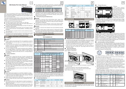
1423H2U Series PLC User ManualCode: 19010034 V2.0Thank you for purchasing the H2U series programmable logic controller (PLC) independently developed by Inovance Control Technology Co., Ltd. Read the manual carefully to be familiar with the product features and be able to use the product safely.This manual describes the specification, features and usage of the H2U series PLC. For the developing environment and design method of user programs, see the Autoshop On-line Help of Inovance.The H2U series PLC has the following features:◆The built-in program memory space reaches up to 16K steps.◆The internal large-capacity power supply can directly apply power tosensors, HMI, and external auxiliary relays.◆It provides multiple high-speed I/O terminals, and has rich motion andpositioning control functions.◆It has four independent communication ports and supports variouscommunication protocols including Modbus, facilitating system integration.◆The comprehensive encryption function protects intellectual propertyrights of the user.◆It comes with fast execution speed and supports up to 128subprograms and 21 interrupt subprograms. Each subprogram has the parameter call and independent password security functions.Safety Information and PrecautionsIn Design◆Provide a safety circuit outside the PLC in the application so that thecontrol system can still work safely even if external power failure or PLC fault occurs.◆In the external circuit of the PLC, an emergency stop circuit, aprotection circuit, an interlock circuit of forward/reverse rotation operation, and position upper/lower limit interlock circuit are necessary to prevent equipment damage ◆The PLC is designed for indoor electric environment and is installed in an overvoltage category 2 environment. A lightning protection device must be installed for the power supply system, so that lighteningovervoltage is not applied on terminals of the PLC, avoiding damage to the equipment.During Installation◆Install the PLC in places free from dust, oil smoke, conducting dust,corrosive gas, combustible gas, high temperature, condensation, wind & rain, vibration and shock. In addition, electric shock, fi re, malfunction may also cause damage and deterioration to the equipment.◆During screw hole processing and wiring, ensure that no metal filingand cable end fall into the ventilation hole of the controller, because such stuff may cause a fi re, fault, or malfunction.◆After installation of the newly purchased PLC is complete, ensure thatthere is no foreign stuff on the surface of ventilation. Failure to comply may result in poor cooling effect during running, which may lead to a fi re, fault or malfunction.◆The installation and wiring must be secure and reliable. Poor contactmay cause malfunction.◆Ensure that all power supplies are cut off before installation or wiring.◆During screw hole processing and wiring, ensure that no metal filings or cable end drops into ventilation holes of the controller. Failure to comply may result in a fi re, fault or malfunction.◆Perform wiring or plug/remove the cable connector only after power-off.◆The specification and installation requirement of external cables mustcomply with the local safety regulations and related IEC standards. The size in the table below is for recommendation.Copper Wire Cross-section Area Recommended CodeAC power wire 1.0–2.0 mm²AWG 12, 18Earthing wire 2.0 mm²AWG12Input signal wire0.8–1.0 mm²AWG18, 20◆The terminal of wire must be insulated according to the local safetyregulations. Ensure that the insulation distance shall not be reduced when the wire is connected to the terminals. Otherwise, electric shock or damage to circuit may result .During Running and Maintenance◆Connection or removal of the communication cable, cables of theextension card and cables of the control unit, or other servicing can be performed only after power-off. Failure to comply may result in damage to the equipment or malfunction.◆Operations such as online modification, forcible output, RUN and STOPProduct Information■Designation RulesH2u-3232MRAX-XP123456789No. NameDescription1Product information H: Inovance controller2Series No.2U: Second generation of controller 3Input points 32: 32 inputs 4Output points 32: 32 outputs5Module classifi cation M: Main module of general-purpose controller, P: Positioning controller, N: Network controller, E: Extension module 6Output type R: Relay, T: Transistor7Power supply type A: 220 VAC (220 VAC by default if null), B: 110 VAC, C: 24 VAC output, D: 24 VDC8Special functionHigh-speed input/output, analog function9XP auxiliary version -◆Basic ParametersPLC Model Total I/Os I/O Features (Input Voltage: 24 VDC)Order Code Total Inputs Hi-Speed Inputs Total Outputs High-Speed Outputs Output TypeH2U-1010MR-XP 2010 2 x 60 kHz6 x 10 kHz 10-Relay 01022078H2U-1010MT-XP 3 x 100 kHz Transistor01022079H2U-1616MR-XP 3216 6 x 60 kHz 16-Relay01022040H2U-1616MT-XP 3 x 100 kHz Transistor01022041H2U-2416MR-XP 4024 2 x 60 kHz4 x 10 kHz 16-Relay 01022048H2U-2416MT-XP 2 x 100 kHzTransistor01022049H2U-2416MTQ-F01 6 x 100 kHz 5 x 100 kHz01028063H2U-3624MR-XP 6036 2 x 60 kHz4 x 10 kHz 24-Relay 01022046H2U-3624MT-XP 2 x 100 kHz Transistor01022047H2U-3232MR-XP 6432 6 x 60 kHz32-Relay01022050H2U-3232MT-XP 3 x 100 kHzTransistor01022045H2U-3232MTQ 6 x 100 kHz 5 x 100 kHz 01022015H2U-3232MTP -8 x 100 kHz01022061H2U-4040MR-XP 8040 6 x 60 kHz 40-Relay01022042H2U-4040MT-XP 3 x 100 kHz Transistor01022062H2U-6464MR-XP 12864 6 x 60 kHz 64-Relay01022043H2U-6464MT-XP3 x 100 kHz Transistor01022044Note: Total inputs include hi-speed inputs. High-speed input terminals can be used for common inputs. Total frequency of H2U-XP high-speed inputs cannot exceed 70 kHz. Total frequency of H2U-3232MTQ and H2U-2416MTQ high-speed inputs cannot exceed 600 kHz. Total frequency of high-speed inputs of other H2U models cannot exceed 100 kHz.At Wiring◆Use shielded cables for high-frequency signal input/output inapplications with severe interference to enhance anti-interference capacity of the system.◆Suitable earthing connection shall be provided by the end system. Theearth wire must be connected only to the earthing point on terminal which is marked with the earth symbol. The earth must be over 2 mm².◆Installation or removal of the extension card can be performed only afterpower-off.◆Make sure to replace button cell after power-off. If replacement at power-on is required, only authorized electrical technician is allowed to complete replacement within 30 seconds. Failure to comply may result in data loss. ◆Treat scrapped PLC as ordinary industrial waste.Environment ParametersUse TransportationStorageTypeParameterUnit M e c h a n i c a l s t r e sSine vibration Shift mm 3.5 (5–9 Hz)--Acceleration m/s 210 (9–150 Hz)--Random vibrationAcceleration spectral density m 2/s 3 (dB/Oct)-5–20 Hz: 1.92 dB 20–200 Hz: -3 dB-Frequency range Hz -5–200-Vibration direction --X/Y/Z -Shock Type--Half-sine -Acceleration m/s 2-180-DipDip heightm-1-Mechanical DesignModel Total I/Os Mounting Dimension Dimension W × H × D (mm)A (mm) B (mm)H2U-1010M_2012080130 x 90 x 88H2U-1616M_32 16080170 x 90 x 88H2U-2416M_4016080170 x 90 x 88H2U-3624M_6021080220 x 90 x 88H2U-3232M_6421080220 x 90 x 88H2U-4040M_8027580285 x 90 x 88H2U-6464M_12834080350 x 90 x 88■Requirements on Installation Position1) Do not remove the paper tape that prevents foreign objects from droppinginto the unit during installation. Once installation is completed, remove the paper tape before power-on so as to prevent overheating.2) To prevent overheating inside the PLC, wall-mount PLC with 300 mmclearance at top and bottom for heat dissipation, as shown in Figure 2.3) Leave 50 mm or more space between PLC and other devices orstructures. Keep PLC far away from high-voltage cables and devices, and power devices.■Mounting Methods1) Mounting or removing PLC Figure 1 Mount or remove PLCDAW BHMounting Hole Ф5 × 4■ Product Structure11. Special function adapter board knock-down hole (It need be cut off before installation of the board.); 12. Wiring terminal for RS485 communication port (COM1/COM2); 13. Special function extension card and special function adapter board interface; 14. System program downloading port (Unauthorized operation is prevented here.); 15. Battery socket (BAT) (Neber reverse the polarity.); 16. Coin battery (provided by Inovance); 17. Special function extension card and special function adapter board fi xed bolts; 18. RUN/STOP switch; 19. User program downloading port (COM0)Note: Fix PLC at both ends with DIN rail slot dampers to prevent it from sliding left and right.2) Mounting and fi xing PLC with screws (wall-mounting mode)In applications with big impct, mount and fi x PLC with four M4 screws.Figure 2 Mount and fi x PLC with four M4 screws2. Buckle the catching groove of PLC base into the DIN rail .3. Press PLC vertically down to the DIN rail .1. Fix the DIN rail onto the mounting plate4. Ensure that the PLC tongue shaped card is locked into the DIN rail .Mounting plate1. Pull down the tongue shape card to make PLC away from the DIN rail .2. Lift the PLC toward you.■Communication Interface Defi nitionThe H2U series PLC has two communication ports and H2U-XP has four communication ports. The COM0 hardware is standard RS485 and RS422, determined by jumper JP0. If JP0 is connected, RS422 is selected. If JP0 is disconnected, the RS422 and RS485 are compatible. COM0 hardware of H2U-XP is standard RS422, which does not require jumper connection. Otherwise, the PLC cannot work normally. The terminal interface is mini-DIN8 socket.⑧①②③④⑤⑥⑦Figure 3 User program downloading port 421485+ 485-COM13485+ 485-COM2Figure 4 RS 485 communication port 421485+ 485-COM13485+ 485-COM25GNDFigure 5 RS 485 communication portNote: Figure 4 is the communication port of H2U-XP . Figure 5 is the communication port of H2U-1010M_XP . COM2 is the COM0 of H2U.PLC can be connected to PC or HMI through COM0 in the following ways:1) (JP0 connected): PLC side is RS422 and PC side is USB. PC isconnected to the PLC COM0 port via the dedicated USB downloading cable (see Figure 3). (The H2U-XP does not require JP0 connection.)2) (JP0 connected): PLC side is RS422 and the PC side is RS232. PC isconnected to the PLC COM0 port via the dedicated serial port download cable (see Figure 3). (The H2U-XP does not require JP0 connection.)3) (JP0 disconnected): PLC side is RS485 and PC side is RS485. They areconnected through the terminal as shown in Figure 4. The connecting cable is determined by the user.■General Specifi cationsEnvironment ParametersUse Transportation Storage Type Parameter Unit C l i m a t e c o n d i t i o nAmbient temperature Low temperature °C -5-40-40High temperature °C 557070Humidity Relative humidity %95 (30 ± 2 °C)95( 40 ± 2 °C)-Air pressureLow pressure kPa 707070High pressurekPa106106106Electrical DesignThe following fi gures show the I/O terminals of the main H2U series PLC unit. The H2U series PLC has different output types, relay and transistor, but has the same terminal confi guration.M4 screwsMounting plate1. Foldaway2. Power supply, auxiliary power supply and detachable terminals for signal input3. Input status indicators4. Running status indicators PWR: Power indicator; RUN: Running indicator: Flashing indicates PLC normal running); B AT: B a t t e r y l o w -v o l t a g e indicator; ERR: Fault indicator5. Mounting holes x 4;6. Cover of extension module interface (R: Relay; T: Transistor)7. DIN rail slot dampers x 2;8. Output status indicator LEDs;9. Detachable terminals for signal output; 10. Cover of user program downloading port (COM0)COM1/COM2 hardware is standard RS485 and is interface terminal. For defi nition of COM1/COM2 , see Figure 4. They are connected to other devices via on-site wiring by the user. Both support the half-duplex communication mode only. COM3 of H2U-XP can be available through extension card.Pin No.Signal DescriptionPin No.Signal Description1RXD-Receive negative data.5+5VProvide power supply +5 V to external devices.It is the same with the internal logic +5 V.2RXD+Receive positive data.6CCSCommunication directioncontrol cable3GNDMust be grounded.No electrical connections for 9 and 107TXD+/RXD+Send positive data toexternal devices.If it is RS485, it can receivepositive data.4TXD-/RXD-Send negative data to external devices.If it is RS485, it can receive negative data (H2U).8NC Non-pinThe following figure shows the internal equivalent circuit of PLC in the relay output mode. The output terminals are divided into several groups, and the groups are electrically isolated. The output contacts of different groups are connected with different power circuits.Figure 8 Internal equivalent circuit of PLC in the relay output mode The following figure shows the internal equivalent circuit of PLC in the transistor output mode.The output terminals are divided into several groups, and the groups are electrically isolated. The transistor output can be used for 24 VDC load circuit only.Figure 9 Internal equivalent circuit of PLC in the transistor output modeProduct Warranty CardCustomerinformationAddress:Company name:Postcode:Contact person:Tel or Email:ProductinformationProduct model:Serial No (Attach here):Name of supplier who supplied you the unit:Failure Description (eg. Fault code)Maintenance personnel:The soft components within [ ] are the battery backup area.• Note 1: Non-battery backup area can be changed into battery backup areavia parameter setting.• Note 2: Battery backup area can be changed into non-battery backup areavia parameter setting.• Note 3: Such permanent battery backup area cannot be changed.■ Programming requirements1) One PC with Microsoft Windows XP or Windows 7 system2) Inovance AutoShop (version 2.0 or above) for the purpose of writing anddownloading user programs3) Inovance USB-mini DIN8 download cable or mouse head download cablefor PC with DB9-type RS232 port■Input SpecificationsThe internal signal circuit composition and external wiring mode of the H2U Series PLC are desribed here. The terminal names in the wiring example vary with the PLC models.The connecting mode is effective to all input points of the PLC.■Output SpecificationsThe H2U series PLC has relay output and transistor output. Their parametersare quite differently. Please select the correct output type so as to avoid misuse. Failure to comply may result in damage to the PLC.The current of transistor output terminals must be less than the allowable maximum current. If the output current of multiple transistor terminals is greater than 100 mA, they should be evenly arranged but not be arranged adjacently, convenient for heat dissipation.It is suggested that the output points, which are set to ON simultaneously, doPLC has a built-in power supply (24 VDC) to detect user switch status, so you only need to connect input signals of dry contact. OC output type is needed if you connect an active transistor or sensor.Output group 0Output group 1Output group 3Output group 0Output group 1Output group 3and for the inductive load in DC circuit, you need add a freewheeling diode, as shown in the following figure.Figure 10 Inductive load absorption circuit,2 WPLC signal input and internal equivalent circuit are shown as Figure 6 below. Circuit of the user and the PLC internal circuit are connected by the terminal. Figure 6 shows the SINK input mode, determined by short connection of the terminal S/S and the terminal 24V.Figure 6 SINK input modeFigure 7 SOURCE input mode24VCOMS /SX0X1X2X2Xn24VDC For self-powered deviceV a r i o u s s i g n a l i n p u t d e v i c e sUser signal wiringI n t e r n a l e q u i v a l e n t c i r c u i t o f P L COutput 3 applies power to sensor. It can also provide external power supply to special function modules. Output 2 provides power supply to the main module and the relay of I/Os of expansion module. Output1 provides power to all modules. During system configuration, make sure that the demand of each power supply does not exceed its maximum capacity.■Terminal Block Definition◆Terminal block definition of H2U-1010MR-XP and H2U-1010MT-XPWhen using H2U-1010MT-XP, Y0, Y1 and Y2 require external powersupply. The user can connect 24VDC(24 V ± 20%) power supply toterminals V+ and V-. Terminal V- hasbeen shorted to COM0 internally. ◆Terminal block definition of H2U-1616MR and H2U-1616MT◆Terminal block definition of H2U-2416MR and H2U-2416MT◆Terminal block definition of H2U-2416MTQ-F01◆Terminal block definition of H2U-3232MTQ (same as that of H2U-3232MTP)■Power S upply Capacitance and Expansion CapacityThe main module and active expansion module of PLC provide power supply toexpansion modules, extension cards and adapters. The I/O points of expansion modules and the number of special function expansion modules must be within the power supply capacitance of the main module or active expansion module.For calculation on power supply capacitance, take the following aspects into considerations:• Each power supply capacitance should be calculated independently.• The expansion capacity is decided by the smaller power supplycapacitance.For example: 24VDD allows connection of six expansion modules, while +5V only allows connection of eight expansion modules. So the system can only be extended up to six expansion modules.■Selection of Extension DeviceWhen designing an H2U series PLC system, we must consider the followingaspects:◆Total I/Os should be within 256 for a main PLC system.◆Power supply capacitance (see Power Supply Specification)◆main modules and active expansion modules can provide 24 VDC and 5VDC power supply to expansion modules and special modules. But total power consumption of all expansion units should be restricted within the power supply capacitance of main module or the active expansion module. ◆The H2U series PLC can be connected to maximum 8 special modules.◆Terminal block definition of H2U-3232MTQ (same as that of H2U-3232MTP)◆Terminal block definition of H2U-6464MR and H2U-6464MT◆。
sennheiser skm 6000 digital handheld transmitter 说

BEnEfiTS–Digital high-performance handheld transmitter with wide selection of capsules for every voice and every stage situation–intermodulation-free even at close proximity to multiple transmitters–Large 88 MHz switching bandwidth ensures flexibility and reliable operation even in demanding Rf environmentsSCoPE of SuPPLy–1 handheld transmitter SKM 6000–1 microphone clamp MZQ 9000–Quick guide–Safety guide The SKM 6000 digital handheld transmitter is equipped for every voice, every song and every demand on the world’s live stages. Maximum transmission reliability is delivered by the renowned Long Range mode superior audio quality by the proprietary Sennheiser Audio Codec (SeDAC) from the wireless masterpiece, Digital 9000. Sophisticated electronics prevent disturbing intermodulation, even with numerous transmitters in the most confined spaces. This allows operation in an equidistant frequency grid and efficiently utilizes the available frequency spectrum.Via Sennheiser’s standard capsule interface, the SKM 6000 transmitter is compatible with microphone heads from evolution wireless G3, 2000, Digital 9000, and the neumann KK 204 / 205 series.A special magnesium housing offers the perfect balance between low weight and roadworthy construction.The BA 60 lithium-ion battery pack ensures up to 5.5 hours of operation. Alternatively, operation is also possible with batteries from the B 60 battery set.The transmitter is fully compatible with the EK 6042 and EM 9046 in Long Range mode.DIGITAL 6000SKM 6000Modulation schemeDigital modulation Long Range ModeAudio codecSeDAC(Sennheiser Digital Audio Codec)frequency range470 to 718 MHz,subdivided into 3 ranges: SKM 6000 A1 – A4: 470 – 558 MHz SKM 6000 A5 – A8: 550 – 638 MHz SKM 6000 B1 – B4: 630 – 718 MHzSwitching bandwidth 88 MHz frequency stability < 5 ppm Tuneability 25 kHz stepsEncryptionAES 256 and Digital 9000 encryptionLower cut-off-frequency (−3 dB)Adjustable: 60 Hz, 80 Hz, 100 Hz, 120 HzRf output power25 mW rms, 50 mW peak Audio frequency response 30 Hz to 20 kHz (3 dB)Audio GainCan be set in 3 dB steps from 0 dB to + 62 dB (for each capsule)operating time 5.5 h (with BA 60 battery pack)Power consumption Max. 960 mW Dimensions (L × D)270 × 40 mm WeightApprox. 350 g(with BA 60 battery pack and ME 9005 microphone module)Technical DataPRoDuCT VARiAnTS–SKM 6000 A1 – A4 Art. no. 506302 –SKM 6000 A5 – A8 Art. no. 506303 –SKM 6000 B1 – B4Art. no. 506304–SKM 6000 A5 – A8 uS Art. no. 506367 –SKM 6000 B1 – B4 uS Art. no. 506368 –SKM 6000 A1 – A2 Cn Art. no. 506322 –SKM 6000 B1 – B4 Cn Art. no. 506323 –SKM 6000 A1 – A4 JP Art. no. 506337 –SKM 6000 A5 – A8 JP Art. no. 506338 –SKM 6000 B1 – B4 JPArt. no. 506339–SKM 6000 A1 – A4 KR Art. no. 506352 –SKM 6000 A5 – A8 KR Art. no. 506353 –SKM 6000 B1 – B4 KR Art. no. 506354SySTEM CoMPonEnTS–EM 6000 –SK 6000 –L 6000CoMPATiBLE WiTH–EM 9046 in LR mode –EK 6042RECoMMEnDED ACCESSoRiES–BA 60 Art. no. 504702 –B 60Art. no. 504700DIGITAL 6000SKM 6000RECoMMEnDED ACouSTiCS /M iCRoPHonE MoDuLESAll capsules with Sennheiser standard capsule interface–MMD 835-1 BK (Dynamic, cardioid, black) Art. no. 502575–MMD 845-1 BK (Dynamic, super-cardioid, black) Art. no. 502576–MME 865-1 BK (Condenser, super-cardioid, black) Art. no. 502581 –MMD 935-1 BK (Dynamic, cardioid, black) Art. no. 502577–MMD 945-1 BK (Dynamic, super-cardioid, black) Art. no. 502579–MMK 965-1 BK (True condenser, switchable, black) Art. no. 502582–MMK 965-1 ni (True condenser, switchable, nickel) Art. no. 502584 –MD 9235 BK (Dynamic, cardioid, black) Art. no. 502585–MD 9235 ni (Dynamic, cardioid, nickel) Art. no. 502586–MD 9235 ni/BK (Dynamic, cardioid, nickel-black) Art. no. 502591–ME 9002 (Electret, omnidirectional, black) Art. no. 502587–ME 9004 (Electret, cardioid, black) Art. no. 502588–ME 9005 (Electret, super-cardioid, black) Art. no. 502589–KK 204 (neumann, cardioid, nickel) Art. no. 008651–KK 204 BK (neumann, cardioid, black) Art. no. 008652–KK 205 (neumann, super-cardioid, nickel) Art. no. 008653–KK 205 BK (neumann, super-cardioid, black) Art. no. 008654。
TURCK图尔克接近开关
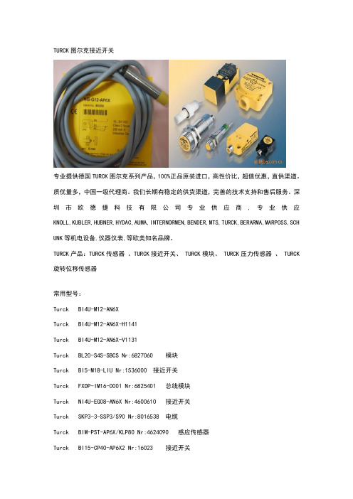
TURCK图尔克接近开关专业提供德国TURCK图尔克系列产品,100%正品原装进口,高性价比,超值优惠,直供渠道。
质优量多,中国一级代理商。
我们长期有稳定的供货渠道,完善的技术支持和售后服务。
深圳市欧德捷科技有限公司专业供应商,专业供应KNOLL,KUBLER,HUBNER,HYDAC,AUMA,INTERNORMEN,BENDER,MTS,TURCK,BERARMA,MARPOSS,SCH UNK等机电设备,仪器仪表,等欧美知名品牌。
TURCK产品:TURCK传感器、TURCK接近开关、 TURCK模块、 TURCK压力传感器、 TURCK 旋转位移传感器常用型号:Turck BI4U-M12-AN6XTurck BI4U-M12-AN6X-H1141Turck BI4U-M12-AN6X-V1131Turck BL20-S4S-SBCS Nr:6827060 模块Turck BI5-M18-LIU Nr:1536000 接近开关Turck FXDP-IM16-0001 Nr:6825401 总线模块Turck NI4U-EG08-AN6X Nr:4600610 接近开关Turck SKP3-3-SSP3/S90 Nr:8016538 电缆Turck BIM-PST-AP6X/KLP80 Nr:4624090 感应传感器Turck BI15-CP40-AP6X2 Nr:16023 接近开关Turck NI8-P18-AZ3/S139-S90 Nr:1350002 感应传感器Turck NI40-CQ80-L1131/S1102 Nr:1602406 传感器Turck BMSWS8151-8,5 Nr:6904722 接头Turck BMWS8151-8,5 Nr:6904721 接头Turck BLCDP-4M12MT-4AI-VI Nr:6811167 总线模块Turck NI4-DS20-2AP6X2-H1141 Nr:1650020 接近开关Turck BC10-QF5,5-RN6X2 Nr:2620128 接近开关Turck WK4T-4 Nr:6915090 接头Turck BI5U-EM18-AP6X 10M 接近开关Turck BL20-S3T-SBB Nr:6827044 总线模块Turck BL20-2AO-U(-10/0...+10VDC) Nr:6827033 总线模块Turck BL20-P4T-SBBC Nr:6827038 总线模块Turck BL20-S6T-SBCSBC Nr:6827064 总线模块Turck FDN20-4S-4XSG Nr:6611359 模块Turck MK1-2RP/24VDC Nr:7505501 安全栅Turck NI10-G18SK-Y1X Nr:40161 接近开关Turck NI15-P30SK-AP6X2 Nr:4660100 接近开关Turck NI30-Q130-VP4X2-B2141 Nr:1518001 传感器Turck B2N45H-Q20L60-2LI2-H1151 Nr:1534013 接近开关Turck P00 Nr:8008578 接头Turck RU30-M18-AP8X-H1141 Nr:1810000 接近开关Turck DNI20U-M30-AP4X2 Nr:1582233 传感器Turck B8141-0(Old:H 8141-0) Nr:69049 接头Turck BL67-B-2M12-P,6827194 Nr:6827194 总线模块Turck BL67-B-2M12 Nr:6827186 总线模块Turck B4151-0/11 Nr:6914526 接头Turck NI20U-M30-AP6X Nr:1646100 接近开关Turck Nr:6827024 模块Turck BS4151-0/11 Nr:6914507 接头Turck BI10S-Q26-AD4X/S34 Nr:44702 传感器Turck Nr:6601590 模块Turck BI1-EG05-Y1 Nr:1003240 接近开关Turck 6905406 HAS8141-0 Nr:6905406 接头Turck BI25-G47-VP4X-B2141 Nr:45902 传感器Turck BMSWS8151-8,5 Nr:6904722 接头Turck IM33-22EX-HI/24VDC Nr:7506441 安全栅Turck BTS-DSC26-EB2 Nr:6900223 模块Turck WAK3-10/P00(Old:RK4T-10) Nr:8007041 接头Turck BMWS8151-8,5 Nr:6904721 接头Turck MS96-12R/230VAC Nr:5231000 安全栅Turck BTS-DSC26-EB3 Nr:6900224 模块Turck LI200P0-Q25LM0-LIU5X3-H1151 Nr:1590002 位移传感器Turck BL67-B-1RSM Nr:6827190 总线模块Turck BI20U-CK40-VP4X2-H1141 Nr:1627216 接近开关Turck FXDP-IM16-0001 Nr:6825401 总线模块Turck BI1,5-EG08WD-AP6X-H1341 Nr:4602210 感应器Turck MK13-P-EXO/24VDC Nr:7542116 隔离器Turck BI5U-MT18E-AP6X-H1141 Nr:1635248 接近开关Turck NI10-K20-Y1 Nr:10072 接近开关Turck NI10-G18-Y1 Nr:10061 接近开关Turck BI10-G30-Y1, Nr:10062 接近开关Turck IM1-12EX-R Nr:7541226 隔离放大器Turck IM31-12EX-I Nr:7506321 隔离放大器Turck SDPL-0404D-0004 Nr:6824175 模块Turck SNNE-04A-0009 Nr:6824201 模块Turck BI5-Q08-VP6X2 Nr:16001 接近开关Turck BI5U-Q12-VP6X2 Nr:1635533 接近开关Turck WAK4-2/P00 Nr:8007046 插头Turck Nr:1533004 接近开关Turck NI35-CP40-AP6X2 Nr:16025 接近开关Turck Bi10-M30-AP6X/S120 Nr:4617010 接近开关Turck IM1-121EX-R Nr:7541229 接近开关Turck NI10-K20-Y1 Nr:10072 接近开关Turck NI12U-M18-AP6X-H1141 Nr:1645140 接近开关Turck BI5-G18K-AP6X-H1141 Nr:4670460 接近开关Turck BI5-G18K-RP6X-H1141 Nr:4670461 接近开关Turck BIM-NST-AP6X-V1131 Nr:4685800 接近开关Turck WAK3-10/S01/S90 8013816 Nr:8013816 电缆Turck BIM-NST-Y1X-H1141 Nr:1058600 接近开关Turck BI5-M18-Y1X-H1141 Nr:40152 接近开关Turck BIM-IKT-Y1X-H1141 Nr:10562 接近开关Turck BIM-UNT-AY1X/S1139 7M 接近开关Turck BIM-INT-Y1X-H1141 Nr:1056801 接近开关Turck NI15-G30-Y1X, Nr:40201 接近开关Turck NI10-P18SK-AZ3X Nr:43511 接近开关Turck MK13-22N-EX0/24VDC Nr:7542110 隔离放大器Turck NI12U-EG18SK-VN4X Nr:1581901 传感器Turck NI12U-M18-AP6X Nr:1645100 接近开关Turck FXDP-IOM88-0001 Nr:6825404 总线模块Turck BI5-P18SK-Y1X, Nr:40360 接近开关Turck NI30-K40SR-VN4X2 Nr:15758 感应传感器Turck NI25-CK40-LIU2-H1141 Nr:1537821 接近开关Turck FXDP-IM8-0001 Nr:6825400 总线模块Turck WAK3-2/P00/S105 Nr:8017085 接头Turck BL67-4AI-V/I Nr:6827222 模块Turck BI10-S30-AP6X 接近开关Turck MS1-12EX0-R Nr:5311103 隔离放大器Turck NI15-S30-AZ3X/S100 Nr:13758 传感器Turck BI1,5-EG08-AP6X-H1341 Nr:4602260 接近开关Turck BIM-UNT-AP6X Nr:4685720 接近开关Turck NI10-M18-Y1X-H1141 Nr:40153 接近开关Turck SKP3-2/S90 Nr:8007332 接头Turck NI35U-CK40-VP6X2-H1141 Nr:1625815 接近开关Turck BIM-UNR-AP6X-0,3-PSG3S Nr:4685831 接近开关Turck MS96-12R/230VAC Nr:5231000 安全栅Turck BL67-GW-DP Nr:6827184 总线模块Turck NI8U-M12-AP6X-H1141 Nr:1644140 接近开关Turck NI50U-CP40-AP6X2-H1141 接近开关Turck BI8-M18-LIU Nr:1535538 接近开关Turck NI15-P30SK-Y1X 接近开关Turck NI20U-M30-AP6X Nr:1646100 接近开关Turck BI1,5-EG08-AP6X-V1131 Nr:4602220 接近开关Turck BS8151-0 Nr:6904611 接头Turck 8FKS5P3 Nr:8008720 接线盒Turck FDNP-L0808H-TT Nr:6603328 总线模块Turck BI15U-CP40-AP6X2-H1141 Nr:1623503 接近开关Turck SDPB-40A-0007 Nr:6824052 总线模块Turck ,XOR Nr:8008527 线缆Turck IM33-22EX-HI/24VDC Nr:7506441 安全栅Turck IM33-11EX-HI/24VDC Nr:7506440 安全栅Turck NI40U-CP40-AP6X2 Nr:1623600 接近开关Turck NI10-K20-Y1 Nr:10072 接近开关Turck NI65R-S32SR-VP44X Nr:1440008 接近开关Turck NI100R-S32XL-VP44X-H1141 Nr:1510301 接近开关Turck NI15-EM30-AP6/S907 Nr:4617412 接近开关Turck BL67-GW-DP Nr:6827184 模块Turck BI5U-M18M-VP4X-H1141 Nr:1581255 传感器Turck JUSTIERSCHIENE JS 025/037 模块Turck NI8-M18-AP6X/S120 Nr:4611230 接近开关Turck MK1-2AP/24VDC Nr:7505500 安全栅Turck Bi5-G18-Y1X Nr:40150 接近开关Turck BI5-G18-Y1X 5M Nr:4015009 接近开关Turck FLDP-IOM248-0001 Nr:6825333 模块Turck Ni2-Q6,5-AP6-0,S304 Nr:1650048 接近开关Turck BI5-M18-Y1X-H1141 Nr:40152 接近开关Turck PS250R-301-LI2UPN8X-H1141 Nr:6833309 压力传感器Turck NI35-CK40-AP6X2-H1141 Nr:1626400 接近开关Turck PS010V-301-LI2UPN8X-H1141 Nr:6833304 压力传感器Turck PKG3M-6 带接头电缆Turck PS001R-304-LI2UPN8X-H1141 压力传感器Turck NI20-CK40-Y1X-H1141 Nr:4065200 接近开关Turck BMSWS8151-8,5 Nr:6904722 接头Turck NI6U-EG08-AP6X-H1341 接近开关Turck FCS-N1/2A4P-AP8X-H1141 Nr:6871032 流量计Turck NI10-P18SK-Y1X Nr:40361 接近开关Turck BMWS8151-8,5 Nr:6904721 接头Turck NI20U-TS12-AP6X2-V1131 接近开关Turck NI10-M18-Y1X-H1141 Nr:40153 接近开关Turck BI4U-M12E-VN44X 传感器Turck IM21-14EX-CDTRI Nr:7505651 隔离放大器Turck FCS-G1/2A4P-VRX/24VDC Nr:6870096 流量传感器Turck IM33-22EX-HI/24VDC Nr:7506441 安全栅Turck BI10U-M30-ADZ30X2 Nr:4282610 传感器Turck FLDP-IOM88-0002 Nr:6825323 模块Turck FLDP-IOM88-0001 Nr:6825322 模块Turck IM21-14-CDTRI Nr:7505650 隔离放大器Turck SE-84X-E524 总线模块Turck NI10-K20-Y1 Nr:10072 接近开关Turck NI15-G30-Y1X Nr:40201 接近开关Turck BIM-PST-AP6X/KLP80 Nr:4624090 接近开关Turck FXDP-XSG16-0001 Nr:6825406 总线模块Turck BI5U-Q08-AP6X2-1XOR-RS4 1608921 Nr:1608921 接近开关Turck 1600801 BI5-Q08-AP6X2/S34-1XOR-RS4 Nr:1600801 接近开关Turck BI5U-Q08-AP6X2-0,6XOR-RS4 1608936 Nr:1608936 接近开关Turck BI2-G12-Y1, ID: 10054 Nr:10054 感应传感器Turck NI20U-M30-ADZ30X2 Nr:4282810 感应传感器Turck BI8U-EM18WD-AP6X-H1141 接近开关Turck NI8-M18E-LIU-H1141 Nr:1536302 接近开关Turck NI8-M18E-VP4X-H1141 接近开关Turck BI1-EG05-AP6X-V1331 Nr:4608640 接近开关Turck VB 接头线缆Turck FXDP-OM16-0001 Nr:6825403 模块Turck Nr:6601590 模块Turck BL20-GW-DPV1 Nr:6827234 模块Turck BL20-PF-24VDC-D Nr:6827007 模块Turck FLDP-IM32-0001 Nr:6825332 模块Turck BL20-E-16DI-24VDC-P Nr:6827231 模块Turck Nr:6827230 模块Turck BI5U-MT18-AP6X-H1141 Nr:1635240 接近开关Turck NI40U-CP40-VP4X2-H1141 1540602 Nr:1540602 接近开关Turck NI20U-MT30-AP6X-H1141 Nr:1646240 接近开关Turck NI3-EG08K-AP6X-V1131,10-30V Nr:4669650 接近开关Turck 6827031 BL20-1CNT-24VDC Nr:6827031 总线模块Turck Bi3u-M12EE-AP6X-H1141 Nr:1634149 总线模块Turck BL20-PF-24VDC-D Nr:6827007 总线模块Turck BIM-UNR-AP6X-0,3-PSG3S Nr:4685831 接近开关Turck NI25U-CK40-AN6X2-H1141 接近开关Turck NI20NF-CP40-VP4X2 Nr:15684 传感器Turck NI40U-CP40-AP6X2 Nr:1623600 接近开关Turck NI25-CK40-LIU2-H1141 Nr:1537821 接近开关Turck PT400R-14-LI3-H1131 Nr:6831414 传感器Turck NI40U-CP40-FDZ30X2 Nr:4280800 传感器Turck DNI20U-M30-AP4X2 Nr:1582233 传感器Turck Bi5-G18-Y1X Nr:40150 接近开关Turck NI5-G12-Y1X Nr:40101 接近开关Turck BI1,5-EG08K-AP6X-V1131 接近开关Turck RSM57-TR2 Nr:6602011 模块Turck NI15U-M18E-AP6X-H1141 接近开关Turck BI2-G12K-AP6X-H1141 Nr:4670260 接近开关Turck NI4-Q12-AZ31X Nr:13102 传感器Turck AL-WWAK3-2/S370 模块Turck NI15U-M30-AD4X 传感器Turck NI60-K90-AZ3X-B2131 传感器Turck Nr:6904721 模块Turck Nr:6904722 模块Turck BS8141-0 Nr:69010 模块Turck BL20-E-8DI-24VDC-P Nr:6827227 模块Turck NI60-K90SR-VP4X2-B1141 接近开关Turck MK1-2AP/24VDC Nr:7505500 总线模块Turck FXDP-IM16-0001 Nr:6825401 总线模块Turck BL20-GW-DPV1 Nr:6827234 总线模块Turck BL20-2DI-120/230VAC-P Nr:6827011 总线模块Turck FXDP-IM8-0001 Nr:6825400 总线模块Turck BL20-2AO-U(-10/0...+10VDC) Nr:6827033 总线模块Turck Nr:6827023 总线模块Turck Ni2-Q6,5-AP6-0,S304 Nr:1650048 接近开关Turck BSN 18 总线模块Turck BIM-NST-AP6X-H1141/S34 总线模块Turck BL20-2DO-24VDC-2A-P Nr:6827026 总线模块Turck PS010V-504-LI2UPN8X-H1141 Nr:6832841 压力传感器Turck BI5-G18-AP6X-B1341 Nr:46963 接近开关Turck PS010V-301-LI2UPN8X-H1141 Nr:6833304 压力传感器Turck BI5-Q08-AN6X2-V1131 Nr:16006 接近开关Turck NI15-M30T-AZ3X Nr:43171 传感器Turck BI5U-Q08-AN6X2 接近开关Turck FCS-GL1/2A4-AP8X-H1141 Nr:6870204 流量计Turck BI2-Q5,5-AP6X-0,3-PSG3M Nr:1613007 接近开关Turck IM33-11EX-HI/24VDC Nr:7506440 安全栅Turck MS1-33EX0-T Nr:5413103 安全栅Turck IM12-22Ex-R Nr:7541233 安全栅Turck PS01VR-504-LI2UPN8X-H1141 Nr:6832300 压力传感器Turck MS1-33EX0-R 安全栅Turck NI35-CP40-AN6X2,10-30V Nr:16225 接近开关Turck NI15-EM30-AP6/S907 Nr:4617412 接近开关Turck NI40-CP80-VN4X2 Nr:15795 传感器Turck BIM-UNT-AP6X Nr:4685720 接近开关Turck NI20U-EM30-AP6X/3D Nr:1646302 接近开关Turck (5)-2RSSWS Nr:6999021 电缆Turck Nr:6601590 接头Turck BI25-G47SR-FZ3X2 Nr:13427 接近开关Turck BI1-EG05-AP6X Nr:4609740 接近开关Turck BI20-G47-AZ3X 接近开关Turck NI15-G30-Y1X Nr:40201 接近开关Turck BI10U-M30-VP4X-H1141 接近开关Turck BIM-INR-AP6X-0,3-PSG3S 接近开关Turck BIM-INR-AP6X 接近开关Turck BI8-M18-AP6X-H1141 Nr:46150 接近开关Turck RU600-M3065-AP8X-H1141 传感器Turck KABEL451-500M 电缆Turck BL67-GW-DPV1 Nr:6827232 总线模块Turck BL67-2RFID-A Nr:6827225 总线模块Turck BI10-M30-VP4X 接近开关Turck BI10-S30-VP4X/S100 12M s-nr:1517201 接近开关Turck PS400R-401-2UP8X-H1141 流量计Turck PS016R-401-2UP8X-H1141 流量计Turck NI8-M12-AD4X Nr:4411235 接近开关Turck PS250R-501-LUUPN8X-H1141 压力传感器Turck BI15-CP40-AP6X2 Nr:16023 接近开关Turck NI35-CP40-Y1X/S100 接近开关Turck BI10NF-M30-AP6X , 16061 接近开关Turck FCS-G1/2A4-AP8X-H1141 Nr:6870004 流量开关Turck NI75U-CP80-VP4X2,Ident-Nr: 1540800 Nr:1540800 编码器Turck NI12U-EG18SK-VN4X Nr:1581901 接近开关Turck BI25-G47SR-FZ3X2 Nr:13427 感应传感器Turck BL20-SWIRE-DIL(5 pcs.) Nr:6827291 总线模块Turck FXDP-XSG16-0001 Nr:6825406 总线模块Turck BL67-GW-DPV1 Nr:6827232 总线模块Turck BL67-4AI-V/I Nr:6827222 总线模块Turck BI50U-Q80-VP4X2-H1141 Nr:1562000 感应传感器Turck FLDP-IOM124-0002 Nr:6825348 总线模块Turck NI25-CK40-LIU2-H1141 Nr:1537821 接近开关Turck IM12-22Ex-R Nr:7541233 安全栅Turck RU100-CP40-AP6X2 Nr:16100 接近开关Turck NI10-G18-Y1X Nr:40151 接近开关Turck FCS-GL1/2A4P-VRX/24VDC Nr:6870097 流量计Turck BIM-UNT-AP6X-0,3-PSG3S 接近开关Turck AL-WWAK3-5/S370 模块Turck BI5-P18SK-Y1X, Nr:40360 接近开关Turck AL-WWAK4-2/S370 模块Turck Bi10-M30-AP6X/S120 Nr:4617010 接近开关Turck DNI12U-M18E-AP4X3 传感器Turck DNI20U-M30-AP4X2 Nr:1582233 传感器Turck RUC30-M30-LIAP8X-H1151 Nr:1840031 接近开关Turck RU30-M30-AP8X-H1141 Nr:18300 接近开关Turck VB2-FSW-FKW-FSW-45 Nr:6996009 模块Turck SKP3-3,6-SSP3/S90 Nr:8039794 带接头电缆Turck NI15-M30-AP6X/S120 Nr:4617210 电缆Turck NI10U-M12-AP6X-H1141 电缆Turck NI15-M30-AP6X/H1141 电缆Turck NI65R-S32SR-VP44X 1440008 接近开关Turck BI10-EM30D-VP6X/S120 4617035 接近开关Turck 2FKM4/S719 Nr:6996024 感应传感器Turck WAK5-1-WAS5/S398 8016479 Nr:8016479 电缆Turck WAKS3-5/P00 电缆Turck Nr:1533004 接近开关Turck SPTT1 总线模块Turck NI3-EG08K-AP6X-V1131,10-30V Nr:4669650 接近开关Turck BI1-EH03-AN7X Nr:1619323 接近开关Turck FCS-G1/2A4-AN8X-H1141 6870034 接近开关Turck BI10-G30-Y1X 接近开关Turck MS25-UI Nr:0508220 安全栅Turck NI8U-S12-AP6X 接近开关Turck BI5-G18-AP6X-B1441 接近开关Turck BL67-B-4M12 Nr:6827187 模块Turck BI1,5-EG08K-Y1 Nr:1003600 接近开关Turck RSM52-2M Nr:6604712 带接头电缆Turck MS24-112-R Nr:0518003 安全栅Turck NI20U-M30-AN6X Nr:1646120 接近开关Turck BMSWS8151-8,5 Nr:6904722 带接头电缆Turck BI15-CP40-AN6X2 接近开关Turck [5]-2RSSWS Nr:6999021 带接头电缆Turck BI10-G30-Y1 Nr:10062 接近开关Turck FCS-G1/2A4-AP8X-H1141 Nr:6870004 流量计Turck RSSW-RKSW451-0,5M Nr:6914117 带接头电缆Turck NI25-Q20-AP6X2-H1141 接近开关Turck Nr:6601590 带接头电缆Turck NI15-G30-Y1X Nr:40201 接近开关Turck NI35-CP40-FDZ30X2 Nr:42235 传感器Turck ,S320/S398 Nr:8010144 带接头电缆Turck RSS-RSS-841-2M 带接头电缆Turck BL67-2AI-TC Nr:6827178 总线模块Turck BL67-2AI-I,6827175 Nr:6827175 总线模块Turck BL20-2AI-I(0/4…20MA) Nr:6827021 总线模块Turck FCS-G1/2A4P-LIX-H1141/D037 Nr:6870058 流量开关Turck NI3-EH6 5K-AP6X-V1131 感应传感器Turck WWAK3P2-2/S90 电缆Turck SWKP3P2-2/S90 电缆Turck WAK4-5/P00/S105 (8021987) 接头电缆Turck [5]-2RSSWS 插头Turck LT200M-R10-LI0-H1151 Nr:1539379 位移传感器Turck BI15-M30-AP6X Nr:4618530 接近开关Turck Bi1,5-EG08K-AP6X-H1341 接近开关Turck DNI12U-M18E-AP4X3 Nr:1582235 感应传感器Turck NI75U-CP80-AP6X2-H1141 Nr:1623805 接近开关Turck LI200P0-Q25LM0-LIU5X3-H1151 Nr:1590002 位移传感器Turck SCHUTZGEHAOUSE SG40/2 (ULTEM) Nr:69497 总线模块Turck JUSTIERSCHIENE JS 025/037 总线模块附件Turck WWAK4P2-10/S90 Nr:8009251 接近开关插头Turck BID2-H12F-AP6/S312 Nr:1688813 接近开关Turck NI15-G30-Y1X Nr:40201 接近开关Turck 4685722, 接近开关Turck NI3-EG08K-AN6X-V1131,4669750 接近开关Turck 8009572 FSM4-2WAK3-2/2XOR Nr:8009572 总线模块电缆Turck NI35U-CK40-ADZ30X2-T,4280443 接近开关Turck BI10U-Q14-AP6X2 Nr:1608700 接近开关Turck Ni20U-M30-AP6X-H1141 Nr:1646140 接近开关Turck MS24-R Nr:0519009 总线模块Turck BI8U-Q10-AP6X2,1662001 感应传感器Turck BI15U-EM30WD-AN6X,1634843 接近开关Turck BIM-UNR-AP6X-0,3-PSG3S Nr:4685831 接近开关Turck BI5U-Q08-AP6X2-V1131,1608900 接近开关Turck NI15-EM30-AP6/S907 Nr:4617412 接近开关Turck NI8-M18-AP6X/S120 Nr:4611230 接近开关Turck ,1590728 位移传感器Turck IM1-12EX-R Nr:7541226 隔离放大器Turck IM31-12EX-I Nr:7506321 隔离放大器Turck 8019171 S366 电缆Turck PS010V-301-LI2UPN8X-H1141 Nr:6833304 压力传感器Turck Ni8-EM18-AP6/S907 Nr:4611231 接近开关Turck VB2-FSW-FKW-FSW-45 Nr:6996009 接头Turck RSSW-RKSW451-6M Nr:6914121 电缆Turck BI10R-Q14-AP6X2-H1141;1407100 接近开关Turck FLDP-IM8-0001 Nr:6825320 总线模块Turck FLDP-IOM1616-0001 Nr:6825338 总线模块Turck FLDP-IOM84-0001 Nr:6825330 总线模块Turck FLDP-IOM88-0001 Nr:6825322 总线模块Turck FLDP-IM16-0001 Nr:6825326 总线模块Turck FLDP-OM16-0001 Nr:6825327 总线模块Turck BI5-Q08-AP6X2-V2131 Nr:1600502 接近开关Turck BI15U-M30E-AP6X-H1141, 接近开关Turck BI1-EG05-AP6X-V1331 Nr:4608640 接近开关Turck BIM-PST-AP6X Nr:46240 接近开关Turck NI75U-Q80-AP6X2-H1141 Nr:1625855 接近开关Turck S304 (8EA-004-1) 接近开关Turck BIM-IKE-AP6X-H1141 Nr:46216 接近开关Turck B8241-0 Nr:69048 接头Turck NI20U-EM30-AP6X Nr:1646300 接近开关Turck NI12U-M18-AP6X 5M 接近开关Turck NI20-M30-AD4X Nr:4466135 传感器Turck NI15-S30-AZ3X/S97 Nr:1375803 传感器Turck NI12U-M18-AP6X-H1141 Nr:1645140 接近开关Turck S34 1613001 接近开关Turck NI8-S18-AZ3X/S97 Nr:1371803 传感器Turck BI5-P18SK-Y1X, Nr:40360 接近开关Turck BI10-S30-AZ3X/S100 Nr:13719 接近开关Turck FDNP-XSG16-TT Nr:6603323 总线模块Turck BS8141-0 Nr:69010 插头Turck BS4151-0/ Nr:6904716 插头Turck MS23-R 安全栅Turck MK13-451EX0-T/230VAC 安全栅Turck TW-R50-B128 Nr:6900504 开关Turck LI400P0-Q25LM0-LIU5X3-H1151 模块Turck IM12-22Ex-R Nr:7541233 隔离放大器Turck NI2-Q9,5-AP6-0,S304 Nr:1650060 传感器Turck IM33-22EX-HI/24VDC Nr:7506441 安全栅Turck NI10-G18SK-VN4X 1572004 接近开关Turck BI30R-W30-DAP6X-H1141 14045 模块Turck BI5-Q08-VP6X2 Nr:16001 接近开关Turck 7030234;TNLR-Q80L400-H1147L 总线模块Turck FCS-G1/2A4-AP8X-H1141 Nr:6870004 流量传感器Turck IM33-22EX-HI/24VDC Nr:7506441 隔离式安全栅Turck BI15-CP40-AN6X2 接近开关Turck 1645620;Ni12U-S18-AN6X-H1141 模块Turck 7030204;TNLR-Q80L400-H1147 模块Turck BI3U-EM12-AP6X2-H1141 接近开关Turck BS8141-0 Nr:69010Turck B8141-0 Nr:69049Turck BL67-2RFID-A Nr:6827225Turck NI15-EM30-AP6/S907 Nr:4617412 接近开关Turck FCS-G1/4A4-AP8X-H1141 Nr:6870101 流量开关Turck 8017415,模块Turck BI4-M12-AP6X-H1141 接近开关Turck BI5-Q08-AP6X2-V1131 Nr:16005 接近开关Turck BI15-CP40-AP6X2 Nr:16023 接近开关Turck NI4U-EG08-AN6X Nr:4600610 接近开关Turck DTNI20U-M30-AP4X2 Nr:1582232 电感式传感器Turck ASS-IES8-PNP s-nr1600702 模块Turck MK33-11EX0-LI/24VDC Nr:7506402 安全栅Turck IM35-22EX-HI/24VDC 7506515 安全栅Turck IM33-22EX-HI/24VDC Nr:7506441 安全栅Turck MK96-VP01 Nr:7525002 安全栅Turck TW-R50-B128 Nr:6900504 安全栅Turck BI2-G12-AZ33X-B3131 Nr:1304032 传感器Turck BL20-BR-24VDC-D Nr:6827006 模块Turck BI15-CP40-LIU Nr:15356 接近开关Turck BL20-P4T-SBBC Nr:6827038 模块Turck BI15-CP40-AP6X2 Nr:16023 接近开关Turck BL20-PF-24VDC-D Nr:6827007 模块Turck NI60-K90-VP4X-B2141 15103 传感器Turck BL20-S3T-SBB Nr:6827044 模块Turck BL20-2AI-PT/NI-2/3 Nr:6827017 模块Turck BL20-GW-DPV1 Nr:6827234 模块Turck NI35-CP40-AP6X2 Nr:16025 接近开关Turck BL20-P4T-SBBC-B 6827042 模块Turck BI5-Q08-AP6X2-V1131 Nr:16005 接近开关Turck BI8U-M18E-VP44X 1634915 传感器Turck BI2-G12SK-Y1X 40110 接近开关Turck NI35-CK40-AP6X2-H1141 Nr:1626400 接近开关Turck BI3-M18-AZ3X/S903 Nr:1302100 传感器Turck NI15-G30SK-RZ3X 43463 传感器Turck WWAK3P2-5/S90 8009239 接头Turck WWAK3P2-10/S90 8009243 接头Turck NI3-EG08K-AP6X/S350 Nr:4669602 接近开关Turck 4430121 接近开关Turck BIM-EG08-AP6X 4621310 接近开关Turck NI20U-M30-AP6X Nr:1646100 接近开关Turck NI15-S30-AZ3X/S100 Nr:13758 传感器Turck NI10-P18SK-AZ3X Nr:43511 传感器Turck FCS-G1/2A4P-LIX-H1141/D037 Nr:6870058 流量计Turck IM21-14-CDTRI Nr:7505650 隔离器Turck Ni40-CP80-VP4X2 15695 接近开关Turck BI4-M12-VP6X-H1141 1633200 接近开关Turck MK13-33EX0-T/230VAC 隔离器Turck MS1-33EX0-R 隔离器Turck BI5-P18-Y1 Nr:10095 接近开关Turck BIM-IKT-Y1X Nr:10560 接近开关Turck PDP-IOM84-0001 总线模块Turck B4151-0/ Nr:6904715 接头Turck Bi25-G47SR-VP4X2 Nr:15648 感应传感器Turck FCS-G1/4A4P-AP8X-H1141 Nr:6870082 流量传感器Turck PS040V-504-2UPN8X-H1141 6832682 压力传感器Turck IM33-11EX-HI/24VDC Nr:7506440 隔离放大器Turck PS010V-301-LI2UPN8X-H1141 Nr:6833304 压力传感器Turck MS22-RI Nr:0508010 总线模块Turck BS8141-0 Nr:69010 附件Turck PKG3Z-6/S90 Nr:6909616 附件Turck NI8-M18E-VP4X-H1141 接近开关Turck BI1,5-EG08-AP6X-V1131 Nr:4602220 接近开关Turck PKG 3M-6/S90 附件Turck PKW 3M-6/S90 附件Turck VB 模块Turck BI25-G47SR-FZ3X2 Nr:13427 接近开关Turck NI10-K20-Y1 ID 10072 接近开关Turck BI2-G12-Y1, ID: 10054 Nr:10054 传感器Turck NI4-DSC26-2Y1X2-H1140 接近开关Turck BL67-8DI-P Nr:6827170 模块Turck FCS-N1/2A4-AP8X-H1141 流量计Turck BL20-2AI-PT/NI-2/3 Nr:6827017 模块Turck BL67-B-2M12 Nr:6827186 模块Turck FXDP-XSG16-0001 Nr:6825406 模块Turck BI10-G30-Y1X 接近开关Turck BI8U-M18M-VP44X-H1141 Nr:6909616 传感器Turck BL67-2AO-I Nr:6827179 模块Turck NI30-Q130-VN4X2-B2141 传感器Turck NI15-M30-AP6X/S120 Nr:4617210 接近开关Turck Bi10-M30-AP6X/S120 Nr:4617010 接近开关Turck SWKP3-5/S90 Nr:8007372 接头Turck NI15-S30-AN6X 接近开关Turck NI40U-CP40-AP6X2 Nr:1623600 接近开关Turck SCHUTZGEHUSE SG40/2 (ULTEM) Nr:69497 模块Turck IM1-451EX-T Nr:7541189 安全栅Turck BI10R-W30-DAN6X-H1141 接近开关Turck MK13-R-EX0/24VDC 安全栅Turck NI20-CP40-Y1X, Nr:10111 接近开关Turck TN-Q80-H1147 Nr:7030007 模块Turck NI12U-M18-AP6X-H1141 Nr:1645140 接近开关Turck BL67-B-4M12 Nr:6827187 模块Turck BI2-EG08K-AP6X Nr:4669400 接近开关Turck B4151-0/ Nr:6904715 接头Turck IM34-11EX-I Nr:7506630 隔离器Turck NI15-M30-AZ3X/S120 Nr:4316506 接近开关Turck NI8-M18-AZ3X/S120 Nr:4310530 接近开关Turck Bi15U-CP40-AP6X2 Nr:1623500 接近开关Turck BI10U-Q14-AN6X2 Nr:1608710 接近开关Turck NI75U-CP80-VP4X2 Nr:1540800 接近开关Turck NI75U-CP80-VP4X2 Nr:1540800 接近开关Turck NI75U-CP80-VP4X2 Nr:1540800 接近开关Turck NI10-G18SK-VN4X 1572004 接近开关Turck FXDP-IM16-0001 Nr:6825401 接近开关Turck FXDP-IM8-0001 Nr:6825400 接近开关Turck FCS-G1/2A4P-VRX/230VAC Nr:6870094 流量传感器Turck FCS-G1/2A4P-LIX-H1141/D037 Nr:6870058 流量传感器Turck IM34-12EX-RI 7506631 隔离放大器Turck 8007046,WAK4-2/P00 接近开关Turck 4571800, BI2-CRS343-AP4X2-H1141/S34 接近开关Turck 4570890, BI2-CRS260-AP4X2-H1141/S34 接近开关Turck P00 8008575 电缆Turck P00 8008573 电缆Turck SKP3-2/S90 电缆Turck WKP3P2-2/S90 电缆Turck Ni15-M30T-AP6X NO 46192 接近开关Turck IM33-22EX-HI/24VDC Nr:7506441 隔离式安全栅Turck B4141-0/ Nr:6914509 电缆Turck BS4141-0/ Nr:6914510 电缆Turck PS400R-504-2UPN8X-H1141 Nr:6832685 压力传感器Turck IM1-451EX-R Nr:7541188 隔离器Turck IM33-11EX-HI 隔离器Turck C3-A30X AC230V 感应传感器Turck C3-A30FX DC24V 感应传感器Turck PS100R-401-LIUP8X-H1141 压力传感器Turck IM21-14EX-CDTRI Nr:7505651 隔离器Turck FKM4-2FSM3/S89 接头电缆Turck WAK40-2/P00 . 接头Turck NI12U-M18-AP6X-H1141 接近开关Turck . 接近开关Turck NI35-CP40-AP6X2 . 接近开关Turck BI5-Q08-AP6X2-V2131 . 接近开关Turck IM34-12EX-RI . 安全栅Turck NI20U-M30-AP6X . 接近开关Turck BI10-EM30D-VP6X/S120 . 接近开关Turck BIM-IKT-Y1X . 接近开关Turck H 8141-0 . 模块Turck . 接近开关Turck BI5-P18-Y1 . 接近开关Turck BI15U-M30-VP44X . 传感器Turck NI4-Q12-AP6X-H1141 . 接近开关Turck MS1-33EX0-R . 安全栅Turck BI30U-CP40-AP6X2 . 接近开关Turck BI3-Q06-AP6X2 . 接近开关Turck BTS-DSC26-EB2 . 模块Turck RM-35H12T-3C25B-C 1M . 编码器Turck NI8U-M12-AP6X-H1141 . 接近开关Turck NI4-DSU35TC-2AP4X2 . 传感器Turck FLDP-IM16-0001 . 模块Turck NI10-M18-Y1X-H1141 . 接近开关Turck BTS-DSU35-EB1 . 模块Turck RU100-CP40-LIUX . 接近开关Turck NI20U-EG30SK-AP6X 1646400 接近开关Turck NI40-CP80-VP4X 15695 接近开关Turck BI10-P30SK-AP6X 46595 接近开关Turck BI10-P30SK-Y1X 40410 接近开关Turck FDNL-S1600-W 总线模块Turck WAKS3-2/S366 Nr:8019161 电缆Turck WAKS4-5/S366 Nr:8019165 电缆Turck S366 Nr:8019171 电缆Turck WWAK3P2-5-SSP3/S90 Nr:8015252 电缆Turck WKSW451-6M Nr:6914131 电缆Turck WAK3-6/P00/S105 Nr:8016341 电缆Turck BI8-M18E-LIU-H1141 1535561 接近开关Turck 4010201 BI2-EM12-Y1X-H1141 感应传感器Turck 6827021 BL20-2AI-I(0/4...20MA) 模块Turck 4688002 BIM-QST-AP6X 5M 模块Turck 6827002 BL20-GW-PBDP-12MB 模块Turck 4685401 BIM-NST-AP6X-H1141/S34 模块Turck NI10-K20-Y1 ID 10072 压力传感器Turck PC025-GI1/4A1M-2APN8X-H1141 压力传感器Turck NI15-S30-VP4X/S100 7M Nr:1514107 接近开关Turck C5-M10 DC24V 感应传感器Turck BI15-CP40-AP6X2 Nr:16023 接近开关Turck NI5-G12SK-AP6X 接近开关Turck Ni25-G47-AZ3X Nr:13089 接近开关Turck NI75U-CP80-AP6X2 Nr:1623800 接近开关Turck NI50U-CP40-VP4X2 接近开关Turck NI15-S30-VP4X/S100 7M Nr:1514107 接近开关Turck NI15-S30-VP4X/S100 7M Nr:1514107 接近开关Turck NI20-CP40-FZ3X2/S100 Nr:13441 接近开关Turck NI20-CP40-VP4X2/S100 Nr:15046 接近开关Turck SG40/2 接近开关防护壳Turck 8017415,模块Turck MK1-2RP/24VDC Nr:7505501 光电开关Turck NI20U-M30-AP6X Nr:1646100 光电开关Turck FXDP-OM16-0001 Nr:6825403 总线模块Turck NI3-EG08-AN6X-H1341 No. 4602860 接近开关Turck RU30-Q30-LUX-H1141 No. 1820005 接近开关Turck NI8-M18-AP6X/S120 Nr:4611230 接近开关Turck BIM-NST-AP6X No. 4685600 接近开关Turck P3-Li-Q25L No. 6901044 模块Turck BIM-NST-AP6X-V1131 Nr:4685800 接近开关Turck M1-Q25L Nr:6901045 模块Turck FCS-G1/2A4P-LIX-H1141/D037 Nr:6870058 流量计Turck LI100P0-Q25LM0-LIU5X3-H1151 Nr:1590001 接近开关Turck NI35U-CK40-VP6X2-H1141 Nr:1625815 接近开关Turck 1650048 Nr:1650048 接近开关Turck BI2-EH6,5K-AP6X Nr:4610000 接近开关Turck 6827175 BL67-2AI-I 模块Turck BMWS8151-8,5 Nr:6904721 接头Turck BL20-S4T-SBBS Nr:6827046 总线模块Turck BS4151-0/11 Nr:6914507 接头Turck Nr:6827023 总线模块Turck B4151-0/11 Nr:6914526 接头Turck BL20-S4T-SBCS Nr:6827063 总线模块Turck BL20-P4T-SBBC Nr:6827038 总线模块Turck Nr:6601590 接头Turck FLDP-IOM84-0001 Nr:6825330 总线模块Turck FLDP-IM8-0001 Nr:6825320 总线模块Turck BL20-GW-DPV1 Nr:6827234 总线模块Turck FLDP-IM16-0001 Nr:6825326 总线模块Turck BMSWS8151-8,5 Nr:6904722 接头Turck BL20-4DI-24VDC-P Nr:6827012 总线模块Turck FCS-G1/2A4P-LIX-H1141 Nr:6870056 流量计Turck Bi5-G18-Y1X Nr:40150 接近开关Turck BI10-G30-Y1X 接近开关Turck PS010V-504-LI2UPN8X-H1141 Nr:6832841 压力开关Turck BMWS8251-8,5 Nr:6904723 接头Turck FLDP-IOM88-0002 Nr:6825323 总线模块Turck MB-2SKP3P3-5-SSP4/S90 接头电缆Turck DNI12U-M18E-AP4X3 Nr:1582235 感应传感器Turck NI15-S30-VP4X/S100 15141 接近开关Turck NI75U-CP80-VP4X2 Nr:1540800 接近开关Turck FCS-GL1/2A4P-VRX/24VDC Nr:6870097 流量计Turck Bi5-M18-AP6X/S100 Nr:4611004 传感器Turck BI8U-M18M-VP44X-H1141 Nr:6909616 传感器Turck 1636140 BI10U-M30-AP6X-H1141 接近开关Turck BL67-4AI-V/I 总线模块Turck BL67-GW-DPV1 总线模块Turck BL67-PF-24VDC 总线模块Turck BL67-8DI-PD 总线模块Turck Bi4-M12-AP6X-H1141 Nr:46070 接近开关Turck MS22-RI Nr:0508010 安全栅Turck NI20-CP40-AN6X2 Nr:16224 接近开关Turck NI20-CP40-AP6X2 Nr:16024 接近开关Turck NI50-K90SR-Y1 Nr:10074 传感器Turck PS01VR-504-LI2UPN8X-H1141 Nr:6832300 压力传感器Turck BI10-P30SK-Y1X 40410 接近开关Turck BI10-P30SK-AP6X 46595 接近开关Turck PS003V-504-LI2UPN8X-H1141 Nr:6832840 压力开关Turck FCS-G1/2A4P-AN8X-H1141 Nr:6870025 流量开关Turck BID2-G180-AP6-H1141/S212 Nr:16885 接近开关Turck 8010144 接头线缆Turck BIM-EG08-AP6X 4621310 接近开关Turck BL67-2AI-TC 模块Turck RUN20-M18KS-AP8X-H1141 接近开关Turck MK31-112-LU/24VDC 安全栅Turck BL67-B-2M12 模块Turck MS1-33EX0-R 安全栅Turck BL67-4AI-V/I 模块Turck TS-400-LI2UPN8X-H1141 接近开关Turck BL67-4AO-V 模块Turck BL20-GW-DPV1 模块Turck BI5-M18-AP6X/S120 Nr:4611030 开关Turck NI15-M30-AP6X/S120 Nr:4617210 开关Turck MK96-VP01 安全栅Turck BL67-B-4M12 模块Turck FLDP-IM16-0001 模块Turck BIM-IKE-AP6X-H1141 接近开关Turck NI20-CP40-AP6X2 接近开关Turck S304 接近开关Turck NI25-CK40-LIU-H1141 接近开关Turck SWKP3-5/S90 模块Turck BI15-CP40-AP6X2 Nr:16023 接近开关Turck RKM52-2-RSM52 Nr:6914150 电缆Turck BI10-G30-Y1 Nr:10062 接近开关Turck RSSW-RKSW451-2M Nr:6914119 电缆Turck NI60-K90-RZ3X-B2131 No 13538 接近开关Turck MB-Q130 No 6946002 模块Turck RK 30-6 No 69165 电缆Turck REP-DN 6825349 模块Turck TNLR-Q80-H1147 7030230 模块Turck Ni15-EM30-AP6/S907-24VDC 接近开关Turck WKB3T-2/S68 连接电缆Turck BI5-G18-AZ3X2-B3331 Nr:13516 接近开关Turck BL20-GW-PBDP-12MB Nr:6827002 总线模块Turck BL20-BR-24VDC-D Nr:6827006 总线模块Turck BL20-PF-24VDC-D Nr:6827007 总线模块Turck BL20-2AI-I(0/4...20MA) Nr:6827021 总线模块Turck FCI-D20A4P-LIX-H1141 ID:6870673 流量开关Turck Nr:6601590 接头Turck BI15-CP40-AP6X2 Nr:16023 接近开关Turck BI5-M18-AP6X/S120 Nr:4611030 开关Turck NI15-M30-AP6X/S120 Nr:4617210 开关Turck 1660350 BI5-P18-AP6/S139-S90 接近开关Turck NI30-K40-AZ3X-B2131 No 43758 接近开关Turck NI30-Q130-ADZ30X2-B1131 No 42100 接近开关Turck BL67-2AI-PT 模块Turck BI5-S18-AP6X-H1141 接近开关Turck BI2U-EG08-AN6XTurck BI2U-EG08-AN6X-H1341Turck BI2U-EG08-AN6X-V1131Turck BI2U-EG08-AP6XTurck BI2U-EG08-AP6X-H1341Turck BI2U-EG08-AP6X-V1131Turck BI2U-EG08-RN6X-V1131。
KSZ9021RN to KSZ9031RNX Migration Guide

KSZ9021RN to KSZ9031RNXMigration GuideRev. 1.1IntroductionThis document summarizes the hardware pin and software register differences for migrating from an existing board design using the KSZ9021RN PHY to a new board design using the KSZ9031RNX PHY. For hardware and software details, consult reference schematic and data sheet of each respective device.Data sheets and support documentations can be found on Micrel’s web site at: .Differences SummaryTable 1 summarizes the supported device attribute differences between KSZ9021RN and KSZ9031RNX PHY devices.Device Attribute KSZ9021RN KSZ9031RNXReduced Gigabit Media Independent Interface (RGMII) RGMII Version 1.3 (power-up default) using off-chip data-to-clock delays with register options to:•Set on-chip (RGMII Version 2.0) delays•Make adjustments and corrections to TXand RX timing pathsRGMII Version 2.0 (power-up default) using on-chip data-to-clock delays with register options to:•Set off-chip (RGMII Version 1.3) delays•Make adjustments and corrections to TXand RX timing pathsTransceiver (AVDDH)Voltage3.3V only 3.3V or 2.5V (commercial temperature only)Digital I/O (DVDDH)Voltage3.3V or 2.5V 3.3V, 2.5V or 1.8VIndirect Register Access Proprietary (Micrel defined) –Extended Registers IEEE defined –MDIO Manageable Device (MMD) RegistersEnergy-Detect Power-Down (EDPD) Mode Not Supported Supported for further power consumptionreduction when cable is disconnected; Disabledas the power-up default and enable using MMDregisterIEEE 802.3azEnergy Efficient Ethernet (EEE) Mode Not Supported Supported with:•Low Power Idle (LPI) mode for1000Base-T and 100Base-TX•Transmit Amplitude reduction for10Base-T (10Base-Te)•Associated MMD registers for EEEWake-on-LAN (WOL) Not Supported Supported with:•Wake-up using detection of Link Status,Magic Packet, or Custom-Packet•PME_N interrupt output signal•Associated MMD registers for WOL Table 1. Summary of Device Attribute Differences between KSZ9021RN and KSZ9031RNXPin DifferencesTable 2 summarizes the pin differences between KSZ9021RN and KSZ9031RNX PHY devices. Pin #KSZ9021RNKSZ9031RNXPin NameType Pin FunctionPin NameTypePin Function1 AVDDH P 3.3V analog V DD AVDDH P 3.3V/2.5V (commercial temp only) analog V DD 12 AVDDH P 3.3V analog V DD AVDDH P 3.3V/2.5V (commercial temp only) analog V DD 13VSS_PSGndDigital groundNC–No connectThis pin is not bonded and can be connected to digital ground for footprint compatibility with the Micrel KSZ9021RN Gigabit PHY.16 DVDDH P3.3V / 2.5V digital V DD DVDDH P 3.3V, 2.5V, or 1.8V digital V DD_I/O 17 LED1 /PHYAD0I/OLED Output:Programmable LED1 OutputConfig Mode:The pull-up/pull-down value is latched as PHYAD[0] during power-up / reset.LED1 /PHYAD0 /PME_N1I/O LED1 output:Programmable LED1 outputConfig mode:The voltage on this pin issampled and latched during the power-up/reset process to determine the value of PHYAD[0].PME_N output:Programmable PME_N output (pin option 1). This pin function requires an external pull-up resistor to DVDDH (digital V DD_I/O ) in a range from 1.0k Ω to 4.7k Ω. When asserted low, this pin signals that a WOL event has occurred.When WOL is not enabled, this pin function behaves as per the KSZ9021RN pin definition.This pin is not an open-drain for all operating modes.34 DVDDH P3.3V / 2.5V digital V DD DVDDH P 3.3V, 2.5V, or 1.8V digital V DD_I/O38 INT_N O Interrupt OutputThis pin provides aprogrammable interrupt output and requires an external pull-up resistor to DVDDH in the range of 1K to 4.7K ohms for active low assertion.INT_N/O Interrupt OutputThis pin provides aprogrammable interrupt output and requires an external pull-up resistor to DVDDH in the range of 1K to 4.7K ohms for active low assertion.This pin is an open-drain.PME_N2 PME_N output: Programmable PME_N output (pin option 2). When asserted low, this pin signals that a WOL event has occurred.When WOL is not enabled, this pin function behaves as per the KSZ9021RN pin definition. This pin is not an open-drain for all operating modes.40 DVDDH P 3.3V / 2.5V digital V DD DVDDHP3.3V, 2.5V, or 1.8V digitalV DD_I/O47 AVDDH P 3.3V analog V DD NC–NoconnectThis pin is not bonded and canbe connected to AVDDH powerfor footprint compatibility withthe Micrel KSZ9021RN GigabitPHY.48 ISET I/O Set transmit output levelConnect a 4.99KΩ 1%resistor to ground on thispin. ISET I/O Set the transmit output levelConnect a 12.1kΩ 1% resistorto ground on this pin.Table 2. Pin Differences between KSZ9021RN and KSZ9031RNXStrapping Option DifferencesThere is no strapping pin difference between KSZ9021RN and KSZ9031RNX.Register Map DifferencesThe register space within the KSZ9021RN and KSZ9031RNX consists of direct-access registers and indirect-access registers.Direct-access RegistersThe direct-access registers comprise of IEEE-Defined Registers (0h – Fh) and Vendor-Specific Registers (10h – 1Fh). Between the KSZ9021RN and KSZ9031RNX, the direct-access registers and their bits have the same definitions, except for the following registers in Table 3.Direct-access RegisterKSZ9021RN KSZ9031RNXName Description Name Description3h PHYIdentifier2 Bits [15:10] (part of OUI) – same asKSZ9031RNXBits [9:4] (model number) – unique forKSZ9021RNBits [3:0] (revision number) – uniquedepending on chip revision PHY Identifier 2 Bits [15:10] (part of OUI) – same asKSZ9021RNBits [9:4] (model number) – unique forKSZ9031RNXBits [3:0] (revision number) – uniquedepending on chip revisionBh ExtendedRegister –Control Indirect Register AccessSelect read/write control andpage/address of Extended RegisterReserved ReservedDo not change the default value ofthis registerCh ExtendedRegister –Data Write Indirect Register AccessValue to write to Extended RegisterAddressReserved ReservedDo not change the default value ofthis registerDh ExtendedRegister –Data Read Indirect Register AccessValue read from Extended RegisterAddressMMD Access –ControlIndirect Register AccessSelect read/write control and MMDdevice addressEh Reserved ReservedDo not change the default value ofthis register MMD Access –Register/DataIndirect Register AccessValue of register address/data for theselected MMD device address1Fh, bit [1] Software Reset 1 = Reset chip, except all registers0 = Disable resetReserved ReservedTable 3. Direct-access Register Differences between KSZ9021RN and KSZ9031RNXIndirect-access RegistersThe indirect register mapping and read/write access are completely different for the KSZ9021RN (uses Extended Registers) and KSZ9031RNX (uses MMD Registers). Refer to respective devices’ data sheets for details.Indirect registers provide access to the following commonly used functions:•1000Base-T link-up time control (KSZ9031RNX only)• Pin strapping status• Pin strapping override•Skew adjustments for RGMII clocks, control signals, and datao Resolution of skew steps are different between KSZ9021RN and KSZ9031RNX•Energy-Detect Power-Down Mode enable/disable (KSZ9031RNX only)•Energy Efficient Ethernet function (KSZ9031RNX only)•Wake-on-LAN function (KSZ9031RNX only)Revision HistoryRevision Date Summary of ChangesMigration Guide created1.0 12/7/121.1 6/7/13 Indicate PME_N1 (pin 17) for KSZ9031RNX is not an open-drain.Indicate INT_N (pin 38) is an open-drain for KSZ9021RN, but is not an open-drain for KSZ9031RNX.Indicate direct-access register 1Fh, bit [1] difference.。
- 1、下载文档前请自行甄别文档内容的完整性,平台不提供额外的编辑、内容补充、找答案等附加服务。
- 2、"仅部分预览"的文档,不可在线预览部分如存在完整性等问题,可反馈申请退款(可完整预览的文档不适用该条件!)。
- 3、如文档侵犯您的权益,请联系客服反馈,我们会尽快为您处理(人工客服工作时间:9:00-18:30)。
BUK95/96/9E4R4-40BTrenchMOS™ logic level FETRev. 02 — 13 October 2003Product data1.Product profile1.1DescriptionN-channel enhancement mode field-effect power transistor in a plastic package using Philips High-Performance Automotive (HPA) TrenchMOS™ technology.1.2Features1.3Applications1.4Quick reference data2.Pinning information[1]It is not possible to make connection to pin 2 of the SOT404 package.s Very low on-state resistance s Q101 compliants 175°C rateds Logic level compatible.s Automotive systemss 12 V loadss Motors, lamps and solenoidss General purpose power switching.s E DS(AL)S ≤961mJ s R DSon =3.9m Ω(typ)s I D ≤75As P tot ≤254W.Table 1:Pinning - SOT78, SOT404, and SOT226 simplified outlines and symbol Pin Description Simplified outlineSymbol1gate (g)SOT78 (TO-220AB)SOT404 (D 2-PAK)SOT226 (I 2-PAK)2drain (d)[1]3source (s)mbmounting base,connected to drain (d)MBK10612mb3132MBK116mbMBK112123mbsdgMBB0763.Ordering information4.Limiting values[1]Current is limited by power dissipation chip rating [2]Continuous current is limited by package.Table 2:Ordering informationType numberPackage NameDescriptionVersion BUK954R4-40B TO-220AB Plastic single-ended heat-sink mounted package SOT78BUK964R4-40B D 2-P AK Plastic single-ended surface mounted package SOT404BUK9E4R4-40BI 2-P AKPlastic single-ended low-profile packageSOT226Table 3:Limiting valuesIn accordance with the Absolute Maximum Rating System (IEC 60134).Symbol Parameter Conditions Min Max Unit V DS drain-source voltage (DC)-40V V DGR drain-gate voltage (DC) R GS =20k Ω-40V V GS gate-source voltage (DC)-±15V I Ddrain current (DC)T mb =25°C; V GS =5V;Figure 2and 3[1]-174A [2]-75A T mb =100°C; V GS =5V;Figure 2[2]-75A I DM peak drain current T mb =25°C; pulsed; t p ≤10µs;Figure 3-697A P tot total power dissipation T mb =25°C;Figure 1-254W T stg storage temperature −55+175°C T j junction temperature −55+175°C Source-drain diodeI DR reverse drain current (DC)T mb =25°C[1]-174A [2]-75A I DRMpeak reverse drain currentT mb =25°C; pulsed; t p ≤10µs -697A Avalanche ruggednessE DS(AL)S non-repetitive drain-source avalancheenergyunclamped inductive load; I D =75A;V DS ≤40V; V GS =5V; R GS =50Ω;starting T mb =25°C-961mJV GS ≥5VFig 1.Normalized total power dissipation as a function of mounting base temperature.Fig 2.Continuous drain current as a function ofmounting base temperature.T mb =25°C; I DM single pulse.Fig 3.Safe operating area; continuous and peak drain currents as a function of drain-source voltage.03na1904080120050100150200T mb (°C)P der (%)03nl57050100150200050100150200T mb (°C)I D (A)Capped at 75 A due to packageP der P totP tot 25C °()-----------------------100%×=03nl5811010210310-11 10102V DS (V)I D (A)DC100 ms10 ms Limit R DSon = V DS /I D1 mst p = 10 µs100 µsCapped at 75 A due to package5.Thermal characteristics5.1Transient thermal impedanceTable 4:Thermal characteristicsSymbol ParameterConditionsMin Typ Max Unit R th(j-mb)thermal resistance from junction to mounting baseFigure 4--0.59K/WR th(j-a)thermal resistance from junction to ambient SOT78 (TO-220AB)vertical in still air -60-K/W SOT226 (I 2-P AK)vertical in still air-60-K/W SOT404 (D 2-P AK)minimum footprint; mounted on a PCB-50-K/WFig 4.Transient thermal impedance from junction to mounting base as a function of pulse duration.03nl59single shot0.20.10.050.0210-310-210-1110-610-510-410-310-210-11t p (s)Z th(j-mb) (K/W)δ = 0.5t pt p T PtTδ =6.CharacteristicsTable 5:CharacteristicsT j=25°C unless otherwise specifiedSymbol Parameter Conditions Min Typ Max Unit Static characteristicsV(BR)DSS drain-source breakdownvoltage I D=0.25mA; V GS=0VT j=25°C40--V T j=−55°C36--VV GS(th)gate-source threshold voltage I D=1mA; V DS=V GS;Figure9T j=25°C 1.1 1.52VT j=175°C0.5--VT j=−55°C-- 2.3V I DSS drain-source leakage current V DS=40V; V GS=0VT j=25°C-0.021µAT j=175°C--500µA I GSS gate-source leakage current V GS=±15V; V DS=0V-2100nAR DSon drain-source on-stateresistance V GS=5V; I D=25A;Figure7and8T j=25°C- 3.9 4.4mΩT j=175°C--8.3mΩV GS=4.5V; I D=25A-- 4.8mΩV GS=10V; I D=25A- 3.64mΩDynamic characteristicsQ g(tot)total gate charge V GS=5V; V DD=32V;I D=25A;Figure14-64-nCQ gs gate-to-source charge-11-nC Q gd gate-to-drain (Miller) charge-24-nCC iss input capacitance V GS=0V; V DS=25V;f=1MHz;Figure12-53437124pFC oss output capacitance-9431131pF C rss reverse transfer capacitance-408558pFt d(on)turn-on delay time V DD=30V; R L=1.2Ω;V GS=5V; R G=10Ω-44-nst r rise time-118-ns t d(off)turn-off delay time-197-ns t f fall time-132-ns L d internal drain inductance from drain lead 6mm frompackage to center of die- 4.5-nHfrom contact screw onmounting base to center ofdie SOT78- 3.5-nHfrom upper edge of drainmounting base to center ofdie SOT404/SOT226- 2.5-nHL s internal source inductance from source lead to sourcebond pad-7.5-nHSource-drain diodeV SD source-drain (diode forward)voltageI S =25A; V GS =0V;Figure 15-0.85 1.2V t rr reverse recovery time I S =20A;dI S /dt =−100A/µs V GS =−10V; V DS =30V-70-ns Q rrecovered charge-67-nCTable 5:Characteristics …continued T j =25°C unless otherwise specified Symbol ParameterConditions Min Typ Max UnitT j =25°C; t p =300µs T j =25°C; I D =25AFig 5.Output characteristics: drain current as afunction of drain-source voltage;typical values.Fig 6.Drain-source on-state resistance as a functionof gate-source voltage; typical values.T j =25°CFig 7.Drain-source on-state resistance as a functionof drain current; typical values.Fig 8.Normalized drain-source on-state resistance factor as a function of junction temperature.03nl860701402102803500246810V DS (V)I D (A) 3.63.43.232.82.62.42.21054 3.8Label is V GS (V)03nl85345371115V GS (V)R DSon (m Ω)03nl87345678070140210280350I D (A)R DSon (m Ω)Label V GS (V)10543 3.23.403aa2700.511.52-6060120180T j (°C)aa RDSon R DSon 25C °()----------------------------=I D =1mA; V DS =V GS T j =25°C; V DS =V GSFig 9.Gate-source threshold voltage as a function ofjunction temperature.Fig 10.Sub-threshold drain current as a function ofgate-source voltage.T j =25°C; V DS =25V V GS =0V; f =1MHzFig 11.Forward transconductance as a function ofdrain current; typical values.Fig 12.Input,output and reverse transfer capacitancesas a function of drain-source voltage; typical values.03ng520.00.51.01.52.02.5-6060120180T j (°C)V GS(th) (V)maxtypmin03ng5310-610-510-410-3 10-210-100.511.522.53V GS (V)I D (A)maxtypmin03nl8306012018001428425670I D (A)g fs (S)03nl6002500500075001000010-210-11 10102V DS (V)C (pF)C issC ossC rssV DS =25V T j =25°C; I D =25AFig 13.Transfer characteristics: drain current as afunction of gate-source voltage; typical values.Fig 14.Gate-source voltage as a function of gatecharge; typical values.V GS =0VFig 15.Source (diode forward) current as a function of source-drain (diode forward) voltage; typical values.03nl8402550751000123V GS (V)I D (A)T j = 175 °CT j = 25 °C03nl82012345020406080Q G (nC)V GS (V)V DD = 32 VV DD = 14 V03nl8102550751000.00.30.60.91.2V SD (V)I S (A)T j = 175 °C T j = 25 °C7.Package outlineFig 16.SOT78 (TO-220AB).REFERENCESOUTLINE VERSION EUROPEAN PROJECTIONISSUE DATE IECJEDEC EIAJ SOT78SC-463-lead TO-220ABDD 1qpL123L 1(1)b 1e eb0510 mmscalePlastic single-ended package; heatsink mounted; 1 mounting hole; 3-lead TO-220ABSOT78DIMENSIONS (mm are the original dimensions)A E A 1cNote1. Terminals in this zone are not tinned.QL 2UNIT A 1b 1D 1e p mm2.54q Q A b D c L 2max.3.03.83.615.013.53.302.793.02.72.62.20.70.415.815.20.90.71.31.04.54.11.391.276.45.910.39.7L 1(1)E L 00-09-0701-02-16mounting base分销商库存信息:NXPBUK964R4-40B,118BUK9E4R4-40B,127BUK954R4-40B,127。