Circuit Isolation Techniques 071310 Seshan
共轭聚合物 有机半导体 英文
共轭聚合物有机半导体英文英文回答:Conjugated polymers are a class of organic semiconductors that have alternating single and double bonds along their backbone. This unique structure gives conjugated polymers interesting electrical and optical properties, making them promising candidates for use in various electronic applications.Conjugated polymers are typically synthesized via chemical polymerization techniques, such as oxidative coupling or Heck reaction. The resulting polymers are typically soluble in organic solvents and can be processed into thin films using techniques such as spin coating or drop casting.The electrical properties of conjugated polymers are highly dependent on the degree of conjugation, which is the length of the alternating single and double bond sequence.Longer conjugation lengths lead to higher charge carrier mobility and lower bandgap, making the polymer more conductive and semiconducting, respectively.The optical properties of conjugated polymers are also affected by the degree of conjugation. Longer conjugation lengths lead to absorption and emission of light at longer wavelengths, resulting in a red shift in the polymer's absorption and emission spectra.Conjugated polymers have been used in a variety of electronic applications, including organic solar cells, organic light-emitting diodes (OLEDs), and transistors. In organic solar cells, conjugated polymers act as the active layer, absorbing light and generating charge carriers that are then collected by the electrodes. In OLEDs, conjugated polymers are used as the emitting layer, emitting light when an electric current is applied. In transistors, conjugated polymers are used as the semiconductor channel, controlling the flow of current between the source and drain electrodes.Conjugated polymers are a promising class of materials for use in electronic applications due to their unique electrical and optical properties. Further research is needed to improve the performance and stability of conjugated polymers, but they have the potential to revolutionize the field of electronics.中文回答:共轭聚合物是有机半导体的一种,其主链上交替排列着单键和双键。
常用半导体中英对照表(建议收藏)

常用半导体中英对照表(建议收藏)01.常用半导体中英对照表离子注入机 ion implanterLSS理论 Lindhand Scharff and Schiott theory,又称“林汉德-斯卡夫-斯高特理论”。
沟道效应 channeling effect射程分布 range distribution深度分布 depth distribution投影射程 projected range阻止距离 stopping distance阻止本领 stopping power标准阻止截面 standard stopping cross section退火 annealing激活能 activation energy等温退火 isothermal annealing激光退火 laser annealing应力感生缺陷 stress-induced defect择优取向 preferred orientation制版工艺 mask-making technology图形畸变 pattern distortion初缩 first minification精缩 final minification母版 master mask铬版 chromium plate干版 dry plate乳胶版 emulsion plate透明版 see-through plate高分辨率版 high resolution plate, HRP超微粒干版 plate for ultra-microminiaturization掩模 mask掩模对准 mask alignment对准精度 alignment precision光刻胶 photoresist,又称“光致抗蚀剂”。
负性光刻胶 negative photoresist正性光刻胶 positive photoresist无机光刻胶 inorganic resist多层光刻胶 multilevel resist电子束光刻胶 electron beam resistX射线光刻胶 X-ray resist刷洗 scrubbing甩胶 spinning涂胶 photoresist coating后烘 postbaking光刻 photolithographyX射线光刻 X-ray lithography电子束光刻 electron beam lithography离子束光刻 ion beam lithography深紫外光刻 deep-UV lithography光刻机 mask aligner投影光刻机 projection mask aligner曝光 exposure接触式曝光法 contact exposure method接近式曝光法 proximity exposure method光学投影曝光法 optical projection exposure method 电子束曝光系统 electron beam exposure system分步重复系统 step-and-repeat system显影 development线宽 linewidth去胶 stripping of photoresist氧化去胶 removing of photoresist by oxidation等离子[体]去胶 removing of photoresist by plasma刻蚀 etching干法刻蚀 dry etching反应离子刻蚀 reactive ion etching, RIE各向同性刻蚀 isotropic etching各向异性刻蚀 anisotropic etching反应溅射刻蚀 reactive sputter etching离子铣 ion beam milling,又称“离子磨削”。
杨波LLC第五章第一节翻译
第五章LLC谐振变换器的改进在前一章,我们已经讨论过LLC谐振变换器的特性和设计。
这一章,我们将研究两种改进LLC谐振变换器的方法:磁集成和过载保护。
5.1LLC谐振变换器的磁集成从前面的讨论可知,我们可以根据给定规格设计功率级。
设计参数决定了各个组件的值。
对于这些组件,电力器件和电容从生产商处获得,这反映了当前的额技术水平。
在所有这些组件中,需要电力电子研究员设计和制作的是磁性元器件。
在这一部分,我们将讨论LLC变换的磁设计。
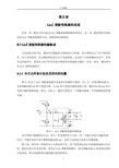
5.1.1分立元件设计法及其存在的问题图5.1给出了LLC谐振变换器中需要设计的磁性元器件,共三个:串联谐振电感Lr,并联谐振电感Lm和T型变压器。
从Lm和T型变压器的结构上看,我们可以将Lm设计为变压器的励磁电感。
所以,实际上,我们只需设计一个谐振电感和一个带励磁电感的变压器。
图5.1LLC谐振变换器的磁构成有几种设计磁器件的方式。
其中一种是利用分立元件,用一个磁芯来设计谐振电感,用另一个磁芯来设计变压器和励磁电感Lm。
这种方法的优点是设计步骤成熟。
接下来,将呈现一种利用分立元件的设计法。
为了将其和后面介绍的磁集成设计法比较,我们会展示其仿真结果。
因为在LLC谐振变换器中,流过谐振电感Lr的是纯对称的交流电流,所以电感和变压器的磁芯采用软铁芯。
图5.2是LLC谐振变换器的分立磁件设计。
两个U型磁芯分别用来设计谐振电感和气隙变压器。
图5.3是磁芯磁感应强度的仿真结果。
每个U型磁芯的有效窗口面积是116.5mm2。
设计结果:n1=12,np:ns:ns=16:4:4,gap1=1.45mm、gap2=0.6mm。
(a)(b)图5.2分立磁件设计的(a)原理图(b)物理结构(a)电感(b)变压器图5.3磁感应强度仿真结果(a)电感(b)变压器图5.3是当输入电压为400V、工作开关频率200kH时各个磁芯的磁感应强度。
如图所示,两个磁芯中的磁感应强度值都十分高。
高磁感应强度的磁芯会导致磁芯损耗。
电子科学与技术专业英语微电子技术分册部分单词

缩略词:BJT 双极结型晶体管Bipolar Junction TransistorLED 发光二极管Light Emitting DiodeMOS 金属氧化物半导体场效应晶体管Metal Oxide SemiconductorFET 场效应晶体管Filed Effect Transistorbcc 体心立方Body-centered cubicfcc 面心立方Face-centered cubicSOI Silicon-On-Insulator绝缘层上硅结构CVD Chemical Vapor Deposition化学气相淀积+ plus/positive - negative * minus / negativeX2X square the square root of X3 x cube the cubic root ofX y X to the yth单词:Semiconductor半导体transition 跃迁Conductivit电导率diffusivity piecewise 分段扩散率resistivity 电阻率diffusivity 扩散系数Bipolar transistor 双极型晶体管step junction 突变结Rectifie 整流器metallurgical junction 合金结Photodiode 光电二极管fermi level 费米能级Leakage current 漏电流exponential 指数的Silicon dioxide 二氧化硅dopant 掺杂Lattice 晶格dielectric 电解质dislodge 移出Unit cell 晶胞Facet 晶面bonding 键合phonon 声子Lattice constant 晶格常数tetrahedral 四面体的Diamond lattice 金刚石晶格Level energy 能级Miller indices 弥勒指数acoustic 声学的Hole 空穴lifetime 寿命Permittivity 介电常数continuity equation连续方程Covalent bonding 共价键impurity 杂质Conduct/valence band 导带,价带device 装置,器件Effective density of states 有效态密度magnetic 有磁性的Intrinsic 本征的illumination 照明silicon ,gallium,germanium,gallium arsenideExtrinsic 非本征的reciprocal 倒数,相反的Carrier 载流子agitation 激动,搅拌Bandgap 能带间隙incremental 增加的Mass action law 质量作用定律excitation 激发Donor acceptor 施主受主Injection 注入collision 冲突,抵触impact ionization 碰撞电离superimposed 叠加sufficient 充分的Scatter 散射Drift 漂移succession 连续的drift velocity 漂移速度Mean free time /path 平均自由时间/程Mobility 迁移率saturation 饱和Recombination 复合spatial 空间overwhelm vt.压倒;淹没;受打击Decay 衰减Abrupt 突变derivative 衍生物bias 偏见gradient 梯度;magnitude 量级Direct Recombination 直接复合Photoconductivity 光电导potential barrier [物] 势垒;[电子] 位垒;voltmeter 电压计quantitative 定量的amplification 放大(率steady state 恒稳态;transient state 瞬态;过渡状态; qualitative .定性的rectification n. [电] 整流equilibrium condition 平衡态endeavor 努力conceive 设想;考虑; postulate.假定unfolding 演变; Prime n. 初期;Primitive 原始的,简单的,粗糙的; artistic adj. 艺术的;supervisor n. 监督人,管理人;检查员;Instinct n. 本能,直觉analog n.模拟;类似物analytical adj. 分析的genuine adj. 真实的,真正的inferior n. 下级;次品acronym n. 首字母缩略词; insofar as 在…的范围内;到…程度; embodiment n. 体现;化身;具体化;proliferate vi. 增殖;扩散;激增vt.使激增;constantly adv. 不断地;时常地; complementary adj. 补足的,补充的; dissipation n. 浪费;消散;[物] 损耗; vehicle n. [车辆] 车辆;工具;交通工具;传播媒介Parallelepiped n. 平行六面体; metallurgical adj. 冶金的;冶金学的; Pedestal n. 基架,基座;analogous adj. 类似的;可比拟的; Ambiguity n. 含糊;不明确;retain vt.保持;雇;记住; Resemblance n. 相似;相似之处prototypical adj. 原型的;典型的; Parasitic adj. 寄生的(等于parasitical);Vestigial adj. 退化的;残余的;发育不全的;parallel n. 平行线平行的Grooves n. 细槽,凹槽simultaneously同时发生地remnant n. 剩余adj. 剩余的;Mount n. 山峰;底座;Acknowledge 承认; disturbance 干扰; inevitable 不可避免的;inherent 固有的; subsume 把。
半导体器件物理与工艺英文版(施敏著)苏州大学出版社课后答案

课后答案网:若侵犯了您的版权利益,敬请来信告知!课后答案网您最真诚的朋友网团队竭诚为学生服务,免费提供各门课后答案,不用积分,甚至不用注册,旨在为广大学生提供自主学习的平台!课后答案网:视频教程网:PPT课件网:课后答案网 w w w .h a c k s h p .c n课后答案网 www.hackshp.cn课后答案网 w w w .h a c k s h p .c n课后答案网 w w w .h a c k s h p .c n课后答案网 w w w .h a c k s h p .c n课后答案网 w w w .h a c k s h p .c n课后答案网 www.hackshp.cn课后答案网 www.hackshp.cn课后答案网 w ww.hackshp.cn课后答案网 w w w .h a c k s h p .c n课后答案网 w w w .h a c k s h p .c n课后答案网 w w w .h a c k s h p .c n课后答案网 w w w .h a c k s h p .c n课后答案网 w w w .h a c k s h p .c n课后答案网 w w w .h a c k s h p .c n课后答案网 w ww .h a c k s h p .c n课后答案网 w ww .h a c k s h p .c n课后答案网 w ww .h a c k s h p .c n课后答案网 w ww .h a c k s h p .c n课后答案网 w ww .h a c k s h p .c n课后答案网 w ww .h a c k s h p .c n课后答案网 w ww .h a c k s h p .c n课后答案网 w ww .h a c k s h p .c n课后答案网 w ww .h a c k s h p .c n课后答案网 w w w .h a c k s h p .c n课后答案网 w ww .h a c k s h p .c n课后答案网 w ww .h a c k s h p .c n课后答案网 w ww .h a c k s h p .c n课后答案网 w ww .h a c k s h p .c n课后答案网 w ww .h a c k s h p .c n课后答案网 w ww .h a c k s h p .c n课后答案网 w ww .h a c k s h p .c n课后答案网 w ww .h a c k s h p .c n课后答案网 w ww .h a c k s h p .c n课后答案网 w ww .h a c k s h p .c n课后答案网 w w w .h a c k s h p .c n课后答案网 w w w .h a c k s h p .c n课后答案网 w w w .h a c k s h p .c n课后答案网 w w w .h a c k s h p .c n课后答案网 w w w .h a c k s h p .c n课后答案网 w w w .h a c k s h p .c n课后答案网 w w w .h a c k s h p .c n课后答案网 w w w .h a c k s h p .c n课后答案网 w w w .h a c k s h p .c n课后答案网 w ww .h a c k s h p .c n。
001 (ISSCC tutorial)Noise Analysis in Switched-Capacitor Circuits

© 2011 IEEE
IEEE International Solid-State Circuits Conference
© 2011 IEEE
Thermal Noise Power
• Nyquist showed that
PSD ( f ) = 4kT
• The total average noise power of a resistor in a certain frequency band is therefore
– Examples: Audio systems, wireless transceivers, sensor interfaces
• Electronic noise directly trades with power dissipation and speed • Electronic noise is a major concern in modern technologies with reduced VDD
• The noise of a MOSFET operating in the triode region is approximately equal to that of a resistor • In the saturation region, the thermal noise can be modeled using a drain current source with power spectral density
• We can model the noise using an equivalent voltage or current generator
2 vn
= Pn ⋅ R = 4kT ⋅ R ⋅ Δf
ISOLATION CIRCUIT

专利名称:ISOLATION CIRCUIT 发明人:TAKAO NOBUTAKA 申请号:JP7624489申请日:19890328公开号:JPH02253707A公开日:19901012专利内容由知识产权出版社提供摘要:PURPOSE:To turn on and off a high frequency signal without fail by providing a cascode amplifier to the signal line of the high frequency signal to be turned on and off and controlling the bias voltage of the cascode amplifier. CONSTITUTION:When a switch SW is turned on, a transistor Q1 is normally biased and transistors Q1 and Q2 are operated as a operated as a cascode amplifier 20. Accordingly, an FM signal from a VCO 1 is amplified by the amplifier 20 and taken out of the collector of the transistor Q2. Further, power amplification is executed to the signal and afterwards, the signal is supplied through a filter 4 to an antenna 5 and transmitted to a base station. On the other hand, when the switch SW is turned off, since an interval between the base and collector of the transistor Q1 is reversely biased through the transistor Q2 and turned off, the signal Sf from the VCO 1 is blocked by the transistor Q1.申请人:SONY CORP更多信息请下载全文后查看。
EL4034 4通道模拟输出终端说明书

Run LED3 Run LED1 Output 10 V Output 30 V EL4034 | 4-channel analog output terminal -10…+10 V, 12b it T he EL4034 analog output terminal generates signals in the range between -10 and +10 V. The voltage is supplied to the process level with a resolution of 12 bits and is electrically isolated. The output channels of the EtherCAT Terminal have a common ground potential. The EL4034 has four channels. Theo utput stages are powered by the 24 V supply. The signal state of the EtherCAT Terminal is indicated by light emitting diodes.EL4034 | ES4034Connection technology2-wire, single-ended Number of outputs4Power supply24 V DC via power contacts Signal voltage-10…+10 V Distributed clocksyes Distributed clock precision<< 1 µs Load> 5 k Ω (short-circuit-proof)Output error< 0.1 % (relative to end value)Resolution12 bit Electrical isolation500 V (E-bus/signal voltage)Conversion time~ 250 µs Current consumption power contactstyp. 25 mA Current consumption E-bustyp. 140 mA Bit width in the process image4 x 16 bit AO output Special featuresOptional watchdog: user-specific output value with ramp; user synchronisation can be activated.Weightapprox. 85 g Operating/storage temperature-25…+60 °C/-40…+85 °C Relative humidity95 %, no condensation Vibration/shock resistanceconforms to EN 60068-2-6/EN 60068-2-27EMC immunity/emissionconforms to EN 61000-6-2/EN 61000-6-4Protect. class/installation pos.IP 20/variable Pluggable wiringfor all ESxxxx terminals Approvals CE, UL, ExRun LED4Run LED2Power contact +24 VPower contact 0 V Output 20 V Output 40 VTop view Contact assemblyEL4034BECKHOFF New Automation Technology We reserve the right to make technical changes.。
- 1、下载文档前请自行甄别文档内容的完整性,平台不提供额外的编辑、内容补充、找答案等附加服务。
- 2、"仅部分预览"的文档,不可在线预览部分如存在完整性等问题,可反馈申请退款(可完整预览的文档不适用该条件!)。
- 3、如文档侵犯您的权益,请联系客服反馈,我们会尽快为您处理(人工客服工作时间:9:00-18:30)。
Circuit Isolation Techniques & TI Isolator TechnologyNeel Seshan Product Marketing Engineer Industrial InterfaceTopicsWhat is Isolation – General information Some Applications Using Isolation Digital Isolation Techniques and Comparison Isolation Terminology & Standards TI Isolation Products Roadmap (for reference)What is Isolation ?Galvanic isolation:Although Circuit 1 and Circuit 2 exchange signals, no current (electrons) pass from Circuit 1 to Circuit 2.Why is isolation required in electrical systems:Break ground loops Reduce common mode noise Safety from high voltagesVoltage supply 1SignalsVoltage supply 2Circuit 1Circuit 2Ground 1Ground 2Isolation Benefits1) Electrical Installation can cause large GPDs (ground potential difference) between two remote nodes. A direct ground connection between the nodes closes the ground loop. Noise sources (i.e. electric motors) inducing large currents into the ground modulate the ground loop current. This ground noise then appears in the signal path. 1) An isolator breaks the ground loop, thus removing signal path noise. The GPD yet still exists and the isolator must be robust enough to withstand the large voltage differences. 2)3)4)2)Why Isolate??Data CAN SN65HVD233 CAN120 Ω120 Ω SN65HVD233Group loop isolationTMP101 SensorISOISO7221CISOISO7221CNoise isolationADS1255 24-Bit OPA333DSPTMS 320 F2810 DSP with CAN ControllerDSPISO7241A LVC2G06 ISO ISO Fan 120V Amp SN75477 Amp AmpISOBlock High VoltageMotor 480VISO721ISO7220MApplications utilizing IsolationIndustrial: • Robotics • PLC input/output isolation • Industrial networks • Motor control • Power suppliesPrimary Task: Isolation between High-Power and Control Signals Isolation of Bus-Nodes to prevent Corruption of the complete Bus & Common Mode RejectionApplications utilizing IsolationMedical: • Microwave therapy • Patient monitoring • Electrocardiographs • Defibrillators Communications: • PBX (Private Branch Exchange) and central office Primary Task: • Telephone terminal equipment Medical: Isolation between Power and Patient • Telephone switching equipment • Modems Communications: Isolation between Power and Caller • ISDN Isolation of Bus-Nodes to prevent • Ethernet / PoECorruption of the complete BusApplications utilizing IsolationConsumer Electronics: • Video (TV, VCR, etc.) • Plasma displays • Electronic gaming • Home appliancesPrimary Task: Isolation between High-Power and UserComputers & Office Equipment • Isolated I/O • Printers and plotters • Fax machinesKey methods of IsolationEwald Georg von Kleist invented the first recorded capacitor 1745Michael Faraday demonstrated the transformer principle in 1831 Zarlink Invented the opto-coupler (1968)Others…Sound, RF, light, Mechanical, etcIsolation Techniques (It’s all capacitive)Source: TI App note SLLA198/iso721(Click on above link for web info)CapacitiveInductiveGMROpticalCapacitive ISO72XInductive ADuM1xxGMR IL7xOptical HCPL-07xxCIOIsolation Dielectric1 pFSiO1 pFPolyimide1.1 pFPolyimide0.6 pFMold compound• All isolated couplers are capacitive coupled (active or parasitic) •CIO for any type is comparableDielectric Materials Used for Isolation• SiO2: ISO72x Typical BV is 1000 Vpeak/um Inorganic Highly Stable (over temperature, moisture, time), high quality Used extensively and for long time as dielectric in semiconductor (low defect rates) Deposited in a controlled semiconductor process Polyimide: ADI Transformer core Typical BV is 250 Vpeak/um Organic Retains moisture – affects lifetime especially at high voltages Used in semiconductor mainly for stress relief & now as isolation barrier Epoxy: Opto-couplers: Typical BV is 50 Vpeak/um Uses filler materials Leaky (higher partial discharge) Applied at packaging as mold compound Voids and anomalies are common••Internal ConstructionOptical: Isolation functionality added at package levelISO72x: Integrated at process levelADuM1100: Integrated at process levelHow are they constructed?Transmit - Chip HV-CapReceiver - ChipHigh Voltage Capacitor DetailMold compoundTop plate = AlBond wireThe change from copper to aluminum as new top plate material simplifies production and assures stable product delivery.Inter Level Dielectric (Tons of SiO2)Min 8µmBottom Plate = Silicon Substrate (doped)How do they work?The LF channel assures correct output signal polarity during loss of input signal (i.e. wire-break) HF and LF channels use differential signaling for high noise immunityHigh-Frequency Channelfor a 50:50 duty cycleCLOCK TRANSFER(Duty Cycle = 50:50)A (IN’) A BBC C D DLow-Frequency ChannelBetween A and D, the LF-channel works in the same way the HF channel does. The only differences are the pulse-width modulation at the beginning and the demodulation at the end.Terminology• Working or Operating Voltage (Vpk): Voltage that may be applied continuously across the Isolation barrier, mostly 560Vpk or 890Vpk • Isolation or Transient Voltage (Vrms): Voltage that may occur temporarily across the barrier (tested per VDE for 1 minute), mostly 4kVpk (relates to 3kVrms per UL, as tested for 10s only) or 6kVpk • Basic or Functional Isolation: - assumes a single level of isolation of certain strength - is applicable for most industrial applications and AC-equipment ≤ 400Vrms, and for consumer electronics. - is mostly rated at 560Vpk continuous, 4kVpk transient voltage. Reinforced Isolation: - assumes a single level of isolation providing the same reliability as a two-layer isolation. - is applicable for most medical applications and AC-equipment > 400Vrms. - is mostly rated at 890Vpk continuous, 6kVpk transient,10kV surge voltage. Medical needs 5kVrms transient. Common Mode Transient Immunity: CMTI discusses the quick change in Reference potential primary to secondary. It’s given as the dV/dt up to which no false toggling of the output will occur (e.g. 35kV/us). Usually scales ~ linearly with Vcc. Creepage and Clearance discusses the surface-distance that may conduct if wet/polluted, respectively the air-distance. For 560V/4kV mostly 5mm is sufficient, for 890V/6kV mostly 8mm is needed. Depends on pollution degree•••CMTICommon-Mode Transient EventSignals referenced to GND2GND1 GND2±∆ V 1 relative ground 2. CMTI – The change in groundMeasured in kV / μSec.Creepage and ClearanceCreepage distance: Shortest distance between two conductive leads, across isolation barrier, measured along surface of insulation. Clearance distance: Shortest distance between two conductive leads , across isolation barrier, measured through air (line of sight).Package/ designationCreepage mmClearance mmNarrow body SOIC/ D Gull wing / DUB Wide body SOIC/ DW4.3 6.8 8.14.8 6.1 8.34How reliable are they?Opto Signaling Rate (Mbps) Propagation Delay Time (ns) Pulse Width Distortion (ns) Channel-to-Channel skew (ns) Part-to-Part Skew (ns) ESD on all Pins (kV) CM Transient Immunity (kV/us) Temperature (oC) MTTF @ 125oC, 90% Confidence (yrs) FIT@ 125oC, 90% Confidence Magnetic Immunity @ 1 kHz (Wb/m2) Radiated Electromagnetic-Field Immunity IEC61000-4-3 (80MHz-1000MHz) MIL-STD 461E RS103 (30MHz-1000MHz) High-Voltage Lifetime Expectancy (yrs) 50 20 2 16 20 ±2 20 -45..125 8 14391 <5 Magnetic 150 32 2 2.0 10 ±2 25 -40..125 1746 65 102 Fails Fails < 10 Capacitive 150 12 1.5 1.6 2 ±4 25 -55..125 2255 50 108 Complies Complies > 28Competitive Comparison Magnetic ImmunityMagneticISO7221C1Mbps: Comparison of Radiated Noise Spectrum –Antenna HorizontalMagnetic: 1Mbps operation @ 5V VccISO7221: 1Mbps operation @ 5V Vcc25Mbps: Comparison of Radiated Noise Spectrum –Antenna HorizontalMagnetic: 25Mbps operation @ 5V VccISO7221: 25Mbps operation @ 5V VccHigh Voltage Lifetime –TDDB (time dependent dielectric breakdown)Competitive Comparison High Voltage LifetimeUsing widely accepted E-Model methodology1.E-051.E-041.E-031.E-021.E-011.E+001.E+011.E+021.E+031.E+0404008001200160020002400280032003600400044004800VrmsT i m e t o f a i l Y e a r sADUM1100ISO72xISO72x: Life expectancy is 28 years at 560Vpeak or 400VrmsCompetition: Life expectancy < 10 yearsHigh Voltage Lifetime: Temperature and Voltage Effect28201511594331230102*********705006007008009001000Vpeak (Working Voltage)L i f e t i m e i n Y e a r sTj = 150C Tj = 100C Tj = 85CDigital Interface Isolation PortfolioSingle Dual TripleQuad FunctionsISO721/2M ISO722xM ISO723xM ISO721/2ISO723xCISO723xA ISO150Bi-directionalAMC1203Delta-SigmaISO724xMISO724xCCF out selectISO724xAX = # back channelsX = # back channelsX = # back channelsISO722xB IsolatedPROFIBUSIsolated5V RS485Isolated3V RS485ISO10505V CANIsolated5/3V RS485w/TransISO742xIsolatedGate DriversISO722xC ISO722xAISO752xCSingle Channel Signal Isolators:ISO72x•4000Vpeak Isolation•560Vpeak continuous •Signaling Rate Options (ISO721B: 5Mbps, ISO721: 100Mbps, ISO721M: 150 Mbps)•UL 1577, IEC 60747-5-2 (VDE 0884, Rev. 2), IEC 61010-1 and CSA Approved • 3.3V/5V Operation (any combination)•25 kV/µs Transient Immunity and High Electromagnetic Immunity•Failsafe Output and High Impedance at Input and Output with Low VccDuals150MbpsTriplesx xx xx designates speed option: A = 1Mbps; C = 25Mbps; M = 150MbpsAll in DW packageQuad-channelx x x x designates speed option: A = 1Mbps; C = 25Mbps; M = 150MbpsAll in DW packageISO308x, ISO1x, ISO3x “Standard RS-485”• 3.3V and 5V•half-duplex and full-duplex(‘176 and ‘180 configuration)•1Mbps and25Mbps•no ISODE outputISO1176 : Isolated RS/485 ProfiBus •5V•half-duplex•25Mbps•optimized for Profibus-Applications •ISODE availableISO1050•5V CAN transceiver•ISO11898 compliant• 3.3V/5V isolated logic interface •High EM Immunity•15kV/us transient immunity•Bus fault protection of -27V to 40V •Dominant timeout function •Thermal Shutdown protection •High Input impedance with low Vcc •1MbpsISO RS-485 with Transformer Driver•Integrated transformer driver•Meets or Exceeds TIA/EIA RS-485•Bus-Pin ESD Protection 16kV GND2 & 6kV GND1•1Mbps / 20Mbps / 40Mbps•1/8 Unit load –256 nodes on a bus•Glitch-Free & Failsafe (Open, Shorted, Idle)•Silicon Integrated SiO 2Insulator•4kVpk / 2500Vrms Isolation, 560V Working -UL1577, IEC 60747-5-2 (VDE 0884, rev. 2) ,IEC 61010-1 & CSA pending•Energy Meter Networks •Power Inverters•Industrial Automation•Building Automation Networks •Motor Control •HVAC•Ease of isolated power design•Fully compliant to RS-485 Standard •High Reliability in Harsh Environments •Optimized for Long Cables Or High Speed •Large buses•Hot pluggable & Protected in all situations •Proven Reliability of SiO 2Insulation, Stable over Time, Temperature & Moisture -Life Span > 25 years @ 125o CEVM –ISO1176TEVM / ISO35TEVM / ISO3086TEVMRTM 3Q1020Mbps1Mbps 40Mbps Speed 5V RS4853V RS485Profibus Function SOIC-16 (DW)Full ISO35T SOIC-16 (DW)Half ISO1176T FullDuplex SOIC-16 (DW)ISO3086TPackage Part #ISO55xx FamilyIGBT Drivers with integrated safety features and adjustability•Silicon Integrated SiO2 Dielectric Capacitor •DESAT protection -fault feedback, soft turn off, UVLO•Adjustable DESAT level & blanking time, soft turn off option, UVLO options•200ns typ prop delay, 20ns typ pulse skew •4KV ESD on All Pins•3V and 5V Vcc1 Supported•5000Vrms Max/ 1200V working voltage -Wide SOIC Packages-UL1577, IEC 60747-5-2IEC 61010-1 & CSA pending•Industrial Motor Control•Industrial Power Supplies/ Inverters•HEV & EV power modules •Proven Reliability of SiO2Dielectric,-Life Span> 25 years•Improved safety & system performance •Unique fine tuning ability without discretes •Enabling low power application•High Immunity for Noisy Environments •High Reliability in Harsh Environments •Flexibility with Power Supplies•Certified by all 3 World Wide agenciesEVM ISO EVM -ISO55XX tbd ISO5513ISO5512ISO5511ISO5510ISO5501ISO5500Part #DESAT adjust, Blanking time adjust, UVLO = 9VDESAT adjust, Blanking time adjust, UVLO = 14VDESAT adjust, Soft turn off option, UVLO = 9VDESAT adjust, Soft turn off option, UVLO = 14VSeparate P and N channel outputs for slope controlP2P compatible with HCPL316JFeaturesWide SOIC-16 10V to 30VWide SOIC-16 15V to 30VWide SOIC-16 15V to 30VWide SOIC-16 15V to 30VWide SOIC-16 15V to 30VWide SOIC-16 10V to 30VPackage Voltage RangeRTM4Q10SamplesnowMotor Control reference designPLC reference designIsolated CAN reference designTI Makes Isolators Easy to UseGet Started TodayEvaluation modulesSamplesApplications supportIBIS modelsData sheetsTechnical documentationApplication notes on:High-Voltage LifetimeMagnetic Field ImmunityISO72x Family of DigitalIsolatorsComplements TI’s industrialproduct portfolio: interface,data converter, DSP, MCU,amplifier, power & logic Contact: Neel Seshan (neels@)Singles, Duals, Triples, QuadsPart Number Pin/Package DescriptionISO7218SOIC, 8SOP Single 100Mbps Digital IsolatorISO721M8SOIC Single 150Mbps Digital IsolatorISO7228SOIC Single 100Mbps Digital Isolator with Enable ISO722M8SOIC Single 150Mbps Digital Isolator with EnablePart Number Pin/Package DescriptionISO7230A16SOIC Triple Channel, 3/0, 1Mbps, Digital Isolator ISO7230C16SOIC Triple Channel, 3/0, 25Mbps, Digital Isolator ISO7230M16SOIC Triple Channel, 3/0, 150Mbps, Digital Isolator ISO7231A16SOIC Triple Channel, 2/1, 1Mbps, Digital Isolator ISO7231C16SOIC Triple Channel, 2/1, 25Mbps, Digital Isolator ISO7231M16SOIC Triple Channel, 2/1, 150Mbps, Digital Isolator Part Number Pin/Package DescriptionISO15012SOP Dual, Isolated, Bi-Directional Digital CouplerISO7220A8SOIC Dual Channel, 2/0, 1Mbps Digital IsolatorISO7220B8SOIC Dual Channel, 2/0, 5Mbps Digital IsolatorISO7220C8SOIC Dual Channel, 2/0, 25Mbps Digital IsolatorISO7220M8SOIC Dual Channel, 2/0, 150Mbps Digital IsolatorISO7221A8SOIC Dual Channel, 1/1, 1Mbps Digital IsolatorISO7221B8SOIC Dual Channel, 1/1, 5Mbps Digital IsolatorISO7221C8SOIC Dual Channel, 1/1, 25Mbps Digital IsolatorISO7221M8SOIC Dual Channel, 1/1, 150Mbps Digital IsolatorISO74208SOIC Low Power Dual Channel IsolatorsISO7420M8SOIC Low-Power Dual-Channel IsolatorsISO74218SOIC Dual Channel, 1/1, 200Mbps Digital IsolatorISO7421M8SOIC Enhanced Temperature Range Dual Channel, 1/1,200Mbps Digital IsolatorPart Number Pin/Package DescriptionISO7240A16SOIC Quad Channel, 4/0, 1Mbps, Digital IsolatorISO7240C16SOIC Quad Channel, 4/0, 25Mbps, Digital IsolatorISO7240CF16SOIC Quad, 4/0, 25Mbps, Digital Isolator, SelectableFailsafeISO7240M16SOIC Quad Channel, 4/0, 150Mbps, Digital Isolator ISO7241A16SOIC Quad Channel, 3/1, 1Mbps, Digital IsolatorISO7241C16SOIC Quad Channel, 3/1, 25Mbps, Digital IsolatorISO7241M16SOIC Quad Channel, 3/1, 150Mbps, Digital Isolator ISO7242A16SOIC Quad Channel, 2/2, 1Mbps, Digital IsolatorISO7242C16SOIC Quad Channel, 2/2, 25Mbps, Digital Isolator ISO7242M16SOIC Quad Channel, 2/2, 150Mbps, Digital IsolatorSINGLES DUALS TRIPLES QUADSIsolated TransceiversPart Number Pin/Package DescriptionISO10508SOP Isolated 5-V CAN TransceiversISO117616SOIC Isolated PROFIBUS RS-485 TransceiverISO1516SOIC Isolated 3.3-V Full & Half-Duplex RS-485 Transceivers ISO308016SOIC Isolated 5-V Full & Half-Duplex RS-485 Transceivers ISO308216SOIC Isolated 5-V Full & Half-Duplex RS-485 Transceivers ISO308616SOIC Isolated 5-V Full & Half-Duplex RS-485 Transceivers ISO308816SOIC Isolated 5-V Full & Half-Duplex RS-485 Transceivers ISO3516SOIC Isolated 3.3-V Full & Half-Duplex RS-485 Transceivers。