黑魔M25动力伞维修维护说明书
维修作业指导书(精品资料).doc
【最新整理,下载后即可编辑】1 目的本作业规范针对维修人员修复不良品过程中焊接及元器件更换的操作指导,有效保证维修质量。
2 适用范围适用于公司生产不良品的整个维修流程。
3.设备和材料电烙铁,热风枪,锡丝,洗板水,防静电刷,离子风机等。
4.作业步骤4.1 维修设备4.1.1 上班前维修员需记录《烙铁头点检表》、《腕带点检表》,确保焊接温度及ESD 防护符合质量要求。
4.1.2 电烙铁焊接温度范围为330℃~390℃,焊接持续时间在3 秒以下。
4.1.3 热风枪的最高温度范围为390℃±30℃,风速控制在6 档(旋钮刻度型)或45 以内(数控显示型)。
4.1.4 离子风机使用请按规范作业。
4.1.5 维修过程中需佩戴静电手环,离位接触产品应佩戴静电手套。
4.2 维修操作规范4.2.1 维修员对不良品进行维修前, 可将产品按测试工位的原则整理/分类后存放于指定区域。
维修时需保持台面整洁,良品及不良品物料应区分标识,维修不良品及维修良品按指定区域放置。
4.2.2 维修员依据最新产品原理图、BOM表,维修WI等对PCBA进行分析/维修,单板功能维修OK后须彻底清洗维修区域及附近组件,测试OK后录入维修模块,跳转首站开始生产。
对于需要更换元器件或焊接的单板,请遵照以下操作规范:4.2.2.1 单板维修OK后生产再次出现的不良品作为返修板修复,同时在维修模块体现维修历史记录,对于第三次产生的返修板(单板第四次不良)须协同技术部分析并记录三次返修板数据,修复后不可投入生产,按照《PCBA报废不良品流程处理》,每一单板允修次数≤3次。
4.2.2.2 维修过程中,同一单板相同器件焊接次数≤4次,每一单板焊接受热次数≤3次,并确保焊接质量。
录入维修模块时需如实记录每个修复动作,以便于质量跟踪。
参考《PCBA返修程序》。
4.2.3 要求说明:拆除/焊接动作计1次,所有维修动作均会体现于维修模块,良品指功能及外观均符合产品质量要求。
联想2500维修手册
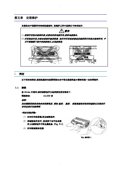
第五章 定期维护为避免由于误操作而导致机器损坏, 在维护工作中应按以下要求执行.警告(1) 拆卸打印机内部零件前,必须先关闭电源开关,拔掉电源插头.(2) 打印机运行后,内部有些部件温度很高. 在打开打印机前盖或后盖拆取打印机内部零件时, 千万不要触摸下图中的阴影部分,以免被烫伤.1. 耗材以下所示的耗材,指在机器的无故障周期内由于老化或损耗至少需要更换一次的零部件.1.1 硒鼓当 Drum 灯亮时,表示硒鼓组件已经快接近使用寿命了. 预期寿命:10,000 页注释:决定硒鼓实际使用寿命的因素很多, 例如 温度、 湿度、 纸张类型和所使用的墨粉以及每次打印作业的打印量等等.<耗材更换步骤>(1) 打开打印机前盖,取出硒鼓组件. (2) 将硒鼓组件放平, 然后按下右手边的锁杆,从硒鼓组件中取出墨粉盒. (Fig. 5-1) (3) 打开新硒鼓的包装.Fig. 第五章-1(4) 将墨粉盒装入新硒鼓中,当听到卡嗒的响声表明墨粉盒已经就位,当墨粉盒安装正确时,锁杆会自动抬起.(Fig. 5-2) (5) 将新硒鼓组件装入打印机中. 打开前盖,打开打印机开关,此时 drum 灯和Alarm 灯亮.Fig. 第五章-2(6) 按住控制面板按钮,直到所有的灯都亮. (显示灯从上向下顺序亮.) 此时硒鼓页数计数器既被复位. (7) 关闭前盖, 此时 Drum 灯应关闭.警告:• 必须使用 联想 生产的专用墨粉. 打印机必须在清洁、无尘、通风良好的环境中使用. • 只有当使用时再打开硒鼓组件的包装. 如果开包的硒鼓受阳光或灯光直接照射,会对硒鼓造成伤害. • 用手拿硒鼓和墨粉盒时应特别注意. 如果墨粉粘在手上或衣服上,应立刻用冷水将其清洗干净. • 当仅仅更换墨粉盒时,不要复位计数器.1.2 墨粉盒墨粉低显示: 每隔 5 秒钟 Data 和 Alarm 灯闪一次. 缺粉显示: Data 和 Alarm 灯每秒闪一次.预期寿命: 3,000 页/标准墨粉盒 6,000 页/大容量墨粉盒(打印 A4- 或 Letter-纸, 5% 打印覆盖率)注释:决定墨粉盒实际使用寿命的因素很多, 例如 温度、 湿度、 纸张类型以及每次打印作业的打印量等等.<更换墨粉盒步骤>(1) 打开前盖,取出硒鼓组件.(2) 将硒鼓放平, 按下右手侧的锁杆,取出墨粉盒. (3) 打开新墨粉盒包装,将墨粉盒轻轻的沿水平方向摇动 5 ~ 6 次. (Fig. 5-3)Fig. 第五章-3(4) 取下保护盖. (Fig. 5-4)(5) 将新墨粉盒装入硒鼓中,当听到卡嗒的响声表明墨粉盒已经就位,当墨粉盒安装正确时,锁杆会自动抬起.Fig. 第五章-4(6) 左右拉动电晕丝清洁滑块,清洁硒鼓组件中的电晕丝 (Fig. 5-5) (7) 将清洁滑快归位.(8) 将硒鼓组件装入打印机中,关闭打印机前盖.Fig. 第五章-5警告:• 更换墨粉盒时,应将硒鼓组件水平放置,以避免墨粉漏出.• 用手拿硒鼓和墨粉盒时应特别注意. 如果墨粉粘在手上或衣服上,应立刻用冷水将其清洗干净.• 只有当使用时再打开墨粉盒包装,打开包装的墨粉盒长期不用,也会减少墨粉寿命. • 开包的硒鼓受阳光或灯光直接照射,会对硒鼓造成伤害. • 只有使用本机指定使用的专用墨粉,才能保证打印质量.• 使用杂牌墨粉不仅会降低打印质量,还会降低打印机的使用寿命.• 清洁完电晕丝后,清洁滑快一定要归位否则会造成打印黑道. (Refer to Fig. 5-5.) • 取下保护盖后,应立刻安装墨粉盒.严禁用手触摸显影辊和感光鼓(如图中阴影部分所示);Fig. 第五章-62.定期更换部件定期更换部件是指为保证打印质量需要定期更换的部件. 这些部件一旦失效对打印质量影响非常大,(即使没有完全损坏或从外表看并未有改变)下表所示为需要定期更换部件及其更换周期. 更换方法,参见第四章“拆卸和重新组装”.注释:上表所列数值,为估算值.如有更改,恕不另行通知.3.定期清理为防止打印机故障或打印图象故障,应对下列部件定期进行清理.小心:硒鼓组件和扫描器窗口的清理可由用户直接操作, 打印机内部和硒鼓上的触点和接头应由维修工程师处理. 告戒用户不要触摸这些部位.3.1 清洁打印机外部清洁打印机外部,保证打印机的清洁干净.1)关闭电源开关,拔下电源线.2)用湿布将打印机外部的灰尘和污物擦掉,等打印机干透后再打开电源开关.警告:用水或中性清洁剂进行清洁. 用酒精等挥发性液体会对打印机表面造成伤害.3.2 清洁硒鼓组件当更换硒鼓组件或更换新墨粉盒后,一定要清洁硒鼓.1)关闭打印机开关,拔掉电源线.2)取出硒鼓组件.3)用电晕丝清洁滑块清洁电晕丝清洁滑快位置 (s)Fig. 第五章-74)将清洁滑快归位小心:清洁后,清洁滑快一定要归位,否则会引起打印黑带.5)将硒鼓组件装入打印机中.3.3 清洁激光扫描器窗口当更换新硒鼓或新墨粉盒后,一定要清洁激光扫描器窗口.1)关闭电源开关,拔掉电源线.2)取出硒鼓组件.3)用干净的软布轻轻擦拭激光扫描器窗口 (下图中箭头所指的深色区域) .Fig. 第五章-8警告:•不要用手指触摸激光扫描器窗口.•不要用酒精清洁激光扫描器窗口.3.4 清洁触点更换硒鼓或墨粉后,一定要清洁打印机内的触点.4)关闭电源开关,拔掉电源线.5)取出硒鼓组件.6)用干净的软布(干布)轻轻擦拭触点 (下图中箭头所指的深色区域) .Fig. 第五章-94.平均故障周期 / 平均维修周期本打印机的平均故障间隔周期和平均故障维修时间如下:平均故障周期: 4,000 小时平均维修时间: 大约 30 分钟。
飞机维修手册 MEL2-25

修理时限 安装数量放行数量 有效 范围项 目 备注或例外25-1 扩音器(Megaphone)(包括STC# ST7659SC-T) D -2允许失效或丢失,但:a) 从客舱拿走不工作的扩音器,b) 保证机上有足够数量的扩音器可用。
注:全载货飞行时不需要该项目。
标牌据情标注修理时限 安装数量放行数量 有效 范围项 目 备注或例外25-3 乘务员座椅组件(单座或双座)1) 需要的乘务员座椅 B --(M)(O) 一个单座或一座椅组件(双座)允许失效,但:a) 该位置无人坐,b) 失效座椅的乘务员使用邻近的乘务员座椅或最靠近失效座椅的旅客座椅,便于其有效的完成指定工作,c) 建立并执行机组手册中的备用程序,d) 折叠式椅子自动收起或固定在收起位置,且e) 指定给乘务员用的旅客座椅上应标有“仅供乘务员使用”字样。
注1:不能自动收起的折叠椅认为是失效的。
注2:限制系统失效或丢失的座位认为失效。
注3:座椅失效时,要考虑到位置和座椅的组合,确保满足接近出口和分配需要的有关规定。
注4:如果双座组件的座椅一侧失效,乘务员需要坐在相邻一侧,则相邻侧的座椅必须正常工作。
2) 额外的乘务员座椅 C --(M) 允许失效,但:a) 该位置无人坐,且b) 折叠式椅子自动收起或固定在收起位置。
注1:不能自动收起的折叠椅认为是失效的。
注2:限制系统失效或丢失的座位认为失效。
3) 全货构型 D --(M) 允许失效,只要该位置无人座。
注:在满足本MEL规定条件下,均允许一个单座或双座的座椅失效,但应通知签派,以便留有旅客座椅供乘务员使用。
标 牌乘务员座椅:在受影响座椅上标注——“失效”,在使用座椅上标注——“只许乘务员使用”机 务(M)乘务员座椅:拆去或把失效座椅可靠固定在收起位。
飞 行(O)座椅失效的乘务员应坐在距出口最近的旅客座位上,乘务员到达紧急出口的时间要与从本来指定的乘务员座位(失效)到达该出口的时间基本一样(2或3秒的时间差也可以认为基本同时)。
MPM维修手册

M P M维修手册(总4页)--本页仅作为文档封面,使用时请直接删除即可----内页可以根据需求调整合适字体及大小--MPM維修手冊一、空氣壓力調節器中過濾器的更換1.關閉印刷機2.斷開印刷機的空氣供應3.確信空氣供應停止器在PEN位置4.打開空氣壓力過濾器筒狀閥,排出剩余的空氣直到空氣壓力表顯示為0PSI5.從印刷機左側后部卸下過濾器6.逆時針方向旋動空氣壓力過濾器筒狀閥,并從調節器上旋下過濾器7.從過濾器上卸下O形密封圈,檢查O形密封圈是否完好,若有損壞,則更換它8.冷子管時針旋轉過濾器主件并卸下調節器主件9.卸下并留下彈簧,德育報廢的過濾器主件10.將彈簧裝在更換好的過濾器主件上,并將過濾器主件裝入調節器,手動旋緊過濾器主件11.在裝好O形密封圈后,將過濾器筒狀閥裝到調節器上12.手動旋緊過濾器筒關閥以至在它被裝好后,可以看到觀測表13.旋緊過濾器導管14.逆時針旋轉調節器旋鈕15.接通印刷機空氣壓力源16.旋轉調節器調節旋鈕使氣壓值為80PSI17.檢查過濾器是否泄漏,若有則糾正18.開啟印刷機確定空氣壓力調節器顯示為80PSI,若有必要則調整空氣壓力調節器19.將調節器裝回印刷機左側后部20.若有必要則關閉印刷機二、鋼板架夾緊裝置的更換1.從主操作界面上選擇50G SQUEEGEE STRDKE,將刮刀架移至印刷機后方2.關閉空氣供應開關3.關閉印刷機,關上MAIN DISCONNECT開關4.打開前門和前罩5.若裝有鋼板架則移走它6.在斷開鋼板架夾緊裝置的上、下空氣管前應在其位置作好標記7.從鋼板架夾緊裝置上斷開空氣管8.取下兩顆將鋼板架夾緊裝置固定在鋼板架軌道上的螺釘,從印刷機上卸下鋼板架夾緊裝罩9.將兩個空氣管安裝到鋼板架夾緊裝置在第6步中所作的位置標記處10.安置更換好的鋼板架夾緊裝置到鋼板架軌道上使它的適合的空氣值以達到印刷機的后方11.用兩個螺釘將鋼板架夾緊裝置固定到鋼板架軌道上12.將供氣開關關閉放在關上13.打開MAIN DISCONNECT開關并開啟印刷機14.在印刷機上安裝一個鋼板架15.從操作蚧面上選擇FRAME CLAMP16.確定在鋼板夾緊裝置空氣連接處沒有空氣泄漏,并且鋼板架夾緊裝置能正確的伸縮17.關門前門和前罩三、驅動馬達的更換1.從主操作界面上選擇JOG GRACK WIPTH,使后傳送軌道完全移至印刷機后部2.從主操作界面上選擇JOG*AXIS,移動X軸到負極限3.關門電源,關門MAIN DISCONNECT開關4.打開前門和前罩,若有需要可卸下左面板5.松開機內的驅動馬達固定螺釘6.移動兩個驅動馬達架來松開驅動帶7.從驅動馬達斷開電源連接器8.記下將驅動馬達連接到固定板上的螺釘孔的位置,移走三顆螺釘9.從驅動馬達皮帶上卸下馬達皮帶,從印刷機上卸下驅動馬達10.松開驅動馬達的兩個螺釘并從驅動馬達軸上卸下皮帶輪11.在更換了的馬達驅動軸上用兩個緊固緊釘裝上并固定驅動馬達皮帶輪12.在把驅動帶裝到驅動馬達皮帶輪上后把更換好的驅動馬達裝好在調整的固定板上13.用3個螺釘安裝并固定驅動馬達到調節板上14.接通驅動馬達的電源15.在驅動馬達和花鍵軸驅動皮帶輪上安裝并調整驅動帶16.用手插壓在驅動帶中間并在機器外側旋動驅動馬達17.當驅動帶中心下壓距離為英寸時旋緊兩個螺釘18.打開電源并執行自動軌道寬度檢查系統四、刮刀驅動帶調整1.若有必要開啟帶調整2.在主操作界面上選擇JOG SQUEEGEE STROKE移動印刷頭至印刷機前部3.打開印刷機前罩和前門4.關門印刷機5.在印刷頭架上卸下固定刮刀驅動罩子的四個螺釘、卸下罩子6.松開四個馬達的螺母7.用手指壓在驅動帶中心,拉動馬達遠離部件馬達皮帶輪8.在驅動中間下壓距離為英寸時旋緊馬達鎖緊螺母9.裝上刮刀驅動帶罩子,用四個螺釘和墊圈來固定它10.關上印刷機前門和前罩五、鋼板擦拭紙的更換1.退回主操作界面2.從Maintenance下拉菜單中選擇change paper3.按NEXT 后攝像系統和鋼板擦拭器將移至印刷機前方4.打開印刷機前蓋可看到真空擦拭器5.將鋼板架推至最后處6.同時抬起左、右兩端的兩個固定裝置并使之向后移動少許7.拉緊左側導紙棍的彈簧,并取出該導紙棍8.取出供應軸和卷動軸9.在供應軸上裝入新紙,在裝紙時應注意裝紙的方向,在機器內側右面有一張相應的鋼板擦器的卷紙路線圖10.根據卷紙路線圈可將供應軸上的新紙固定到卷軸上11.裝上導紙棍后抬起左、右兩端的固定裝置,使其回到固定位置12.在主操作界面上選擇WIPER PAPER按鈕,檢查擦拭紙的卷動情況是否正常轉動,若不正確則需重新調整13.將鋼板拉出至原處14.在主操作界面上選擇CLEAR FANLT,使鋼板擦拭器回復到原位15.關閉前門和前罩六、傳送帶的更換1.打開印刷機2.從主操作界面上選取JOG TRACK WIDTH,如果是正在更換后面的傳送軌道皮帶,輕推后傳送軌道使其在至最前方的一半距離處,如果是正在更換前軌道傳送皮帶,輕推后傳送軌道到印刷機的最后方3.從主操作界面上選擇JOG*AXIS,輕推X軸到其的正極限位置4.關閉印刷機,關閉MAIN DISCONNECT開關5.打開前門和前罩,若有需要的話,可移走左面板6.松開固定傳送皮帶驅動馬達固定板的兩個螺釘,移動馬達內側以松驅動皮帶7.松開兩個用來固定需要更換的傳送帶上的傳送帶張力元件的螺釘8.移動張力元件來減小傳送帶張力,從馬達驅動皮帶輪上卸下傳送帶9.卸下并保留鎖緊墊圈(用來固定后花鍵驅動軸)10.用手輕輕向印刷機后方移動花鍵軸,從前面的花鍵軸驅動軸和后面的承壓墊片之間卸下那個薄墊片11.不斷的向前移動花鍵軸直到有足夠的空隙來卸下或安裝傳送帶,在移動花鍵軸時,不要讓后花鍵軸驅動墊圈從軸上掉下來12.卸下舊的傳送帶13.裝上新的傳送帶在驅動皮輪上14.將薄墊片旋轉在前花鍵軸上并向前移動花鍵軸到印刷機前部,裝上前花鍵軸的承壓墊片15.裝上后花鍵承壓墊片在后花鍵軸進入后方的金屬板上16.用鎖緊墊圈將承壓墊片固定到金屬板上17.在外側旋轉一個壓力表在張力元件上18.在張力元件壓力為10POUNDS時,鎖緊兩個螺釘確定軌道是不動時,后張力元件在恰當的空隙中把金屬板彈出,若需要則調整后傳送軌道的傳送張力19.用手指壓在驅動皮帶的中間位置并在外側拉動傳送驅動馬達20.在中間的驅動皮帶下壓的距離為時鎖緊2個螺釘21.打開MAIN DISCONNECT開關并打開印刷機,執行板傳送軌道傳送帶檢查系統22.慢慢的輕推板傳送軌道,并觀察傳送軌道驅動馬達和后張力元件之間的間隙,確定有還夠的間隙存在23.執行軌道寬度調整檢查系統24.如需要裝好左面板七、傳送帶張力調整1.關閉印刷機2.打開前門和前罩3.檢查前、后傳送軌道的傳送帶,確信他們在所有皮帶輪上工作正常,若需要則更換4.確定前后張力塊的位置,前張力塊在圖3-54中,后張力塊位于鎖緊板的后面5.松開前面張力塊的鎖緊螺釘6.如圖3-54中所示的一樣把壓力表放在前張力塊的尾部7.在壓力表顯示前張力塊為10磅(44N)時,鎖緊張力塊鎖緊螺釘8.打開印刷機9.選擇JOG TRACK WIDITH,并輕推后傳送軌至后張力塊10.關閉印刷機11.重復步驟5-T 來調整后張力塊12.關閉前門和前罩13.如有需要打開印刷機。
D-ASS-205-00 PUNCH Powertrain Service Manual VT2 GreatWall (CN)
.文件名称文件名称TITLE长城Daisy/Dahlia维修服务手册VT2VT2 PUNCH Powertrain Service Manual VT2 for GW Daisy/Dahlia(CN CN))编 制制Set up by发行日期Release Date审 核核Verified by发放号Release No.批 准准Approved By受控状态Status 更改记录MODIFICATION REPORT更改单号 Modification Sheet No.版次Version更改条款Modification Item更改人ModificationPerson更改日期ModificationDate00 首次出版 Min Rui 2009-06-05南京邦奇南京邦奇无级自动变速箱长城Daisy/DahliaVT2 维修服务手册VT2据我们所知,本文中的示意图、技术资料、数据和描述性文字在打印前已经过核对并正确无误。
南京邦奇自动变速箱有限公司(PUNCH Powertrain)公司保留随技术开发和改良不经通过便变更产品价格、规格以及设备保养和维修说明书的权利。
未经南京邦奇自动变速箱有限公司(PUNCH Powertrain)的实现许可,不得使用检索系统复制、存储本出版物的任何部分,也不得以任何形式或方式(无论是以电子、机械、复印、记录或其它方式)进行传播。
尽管我们已经最大努力使本出版物尽可能完整、准确,但本出版物难免出现错误,对此我公司不承担任何责任。
(C)2007南京邦奇自动变速箱有限公司服务手册服务手册南京新港开发区 恒广路19号 邮编:210038 (6)1.概述........................................................................................1.1.传统自动变速器和无级变速器的比较 (7)1.2.变速器剖面图 (8)1.3.无级变速器基本原理 (9)1.3.1.第一组-机械扭矩传递 (9)1.3.1.1行星机构 (9)1.3.1.2多盘离合器 (10)1.3.1.3锥轮和钢带 (10)1.3.1.4中间轴 (11)1.3.1.5差速器 (12)1.3.1.6机械操纵 (13)1.3.1.6.1传动比变化 (13)1.3.1.6.2选档杆处于空档或驻车档 (15)1.3.1.6.3选档杆处于前进档 (16)1.3.1.6.4选档杆处于倒车档 (17)1.3.2.第二组-控制系统 (18)1.3.2.1油泵 (18)1.3.2.2变速器控制装置 (19)1.3.2.3张紧力控制装置 (19)1.3.2.4速比控制装置 (19)1.3.2.5变速器控制单元 (20)1.3.2.5.1TCU接口 (20)1.3.3.第三组-外接装置 (21)1.3.3.1油冷器接口 (21)1.3.3.2选档杆 (22)1.3.3.3主连接器 (22)1.3.3.4扭转减震器 (22)1.4.驾驶策略 (23)1.4.1.特殊情况下的状态 (23)1.4.1.1停车档和空档的功能特性 (23)1.4.1.2D档或R 档功能 (23)1.4.1.2.1常规操作 (23)1.4.1.2.2自适应更新 (24)1.4.1.2.3爬行 (24)1.4.1.2.4怠速停车(只限于前进档状态) (24)1.4.1.2.5加速和减速 (24)1.4.1.2.6加速支持 (25)1.4.1.2.7减速 (25)1.4.1.2.8行驶和制动 (25)1.4.1.2.9驾驶时离合器的结合/分离 (26)1.4.2.故障缺省模式 (26) (27)..................................................... 2.总说明................................2.1.车辆拖运 (27)2.2.保养周期 (27)2.3.润滑油规格 (27)2.4.TCU接线图 (28)2.4.1.TCU接口 (28)2.4.2.变速箱主接头针脚 (29)2.4.3.TCU电路图 (30)2.4.4.TCU 针脚分配 (31)2.4.5.TCU与变速箱之间的接口 (32)2.5.自适应更新 (33) (35)3.使用规程...................................................................................3.1.油位检查说明 (35)3.2.服务零件拆解图 (36)3.3.服务配件清单及扭矩要求 (36)3.4.专用工具及更换服务配件 (45)3.4.1.专用工具 (45)3.4.2.更换服务配件说明 (50)更换差速器油封 (50)更换输入轴油封 (51)更换选档轴油封 (54)更换主动锥轮轴端盖 (57)更换油泵 (58)更换主动锥轮轴滚珠轴承 (59)更换从动锥轮轴端盖 (64)更换油底壳 (64)更换油滤器 (66)更换驾驶模式传感器 (68)更换液压控制块 (70)更换从动锥轮速度传感器及支架 (74)更换主动锥轮速度传感器 (76)更换主接头和内部线束 (76)3.5.电子元件检查表 (80)4.常见问题解答................................ (82)...............................................4.1.漏油 (82)4.2.故障码及采取措施 (83)概述1. 概述变速器传动比的连续变化可通过一种变速装置来实现,该装置包括两个对置的锥轮和一条环绕在两个轮上的V形传动钢带。
AERO-MOTIVE CompanyDA、DB、MA、MB、HA、HB、SA、SB软管卷盘维修手册

DA, DB, MA, MB, HA, HB, SA, SB SeriesHose Reel Service Manual AERO-MOTIVE COMPANYA Woodhead Industries, Inc. SubsidiaryIMPORTANT SAFETY INSTRUCTIONSPlease read this manual carefully and follow its instructions. Improper use or failure to follow these instructions could result in serious injury, death or property damage. Operators should be instructed in the safe and proper use and maintenance of this product. Keep this manual for future reference.The following safety precautions call attention to potentially dangerous conditions.NOTE: Instruct operators in the safe, proper use and maintenance. Keep this manual for future reference. INSTALLATIONMOUNTINGSome reels come complete with hose and are set at proper tension, ready to install. The fixed base ofthe reel allows mounting in several different positions including base up, base down, or wall mounted.Here are general mounting requirements:•Main-shaft must be horizontal.•Centerline of the spool assembly must be in-line with the hose pull out.•When mounted overhead in base up position, add a secondary chain, bracket or other safety device to prevent reel from falling in case the mounting bolts are removed or become loosened fromvibration.SECONDARY SUPPORT CHAINAll reels mounted over head should have a secondary support chain to protect personnel in case ofstructure or mounting component failure. Attach one end of secondary support chain or cable to reel.Attach other end of secondary support chain or cable to a support component other than that whichsupports the reel. The chain or cable should be as short as possible allowing reel to drop no more than 6to 12 inches if the primary connection is released.SUPPLY HOSEAssemble supply hose to main-shaft. Do not use rigid pipe at input connection.Use Teflon tape or pipe sealant to reel hose fitting threads.NOTE: To avoid damage to the swivel, use a wrench to support the swivel fitting while tightening the hose.ADJUSTMENTRATCHET LOCKRatchet lock works with reel mounted in any position and needs no adjustment. Check reel for correctoperation by slowly pulling out the hose. A “clicking” noise will be heard every half revolution of the drum.To latch the reel, pull out the hose and allow it to retract after hearing the first second or third “ click”. Tounlatch, slowly pull out the hose until the “clicking” noise stops, then let the hose retract until the hosestop rests against the hose guide. To disable, ratchet parts must be removed.HOSE GUIDE ARM ADJUSTMENTFor maximum hose life, adjust guide arm so that the hose payout is in line with guide assembly (seeillustration below). To adjust the guide arm, remove screws, and rotate guide arm 90 degrees to nextgroup of mounting holes in stand assembly.TENSION ADJUSTMENTNOTE: Pull hose out completely to insure enough spring revolutions remain for operating. Always leave at least 1-2 turns between full extension and when the spring is wound tight (bottomed out). If entire hoseassembly cannot be pulled out, decrease spring tension until full extension is possible.Reels shipped with hose installed are pre-tensioned at the factory. Reels shipped without hose requirepre-tensioning after hose is installed and before making final hose connections. To pre-tension hosereel, pull hose out far enough to allow one full wrap of hose to be looped back over drum assembly.Hold, drum from turning and loop hose back on drum. Repeat steps above until desired tension isachieved. After tension is set, pull hose out completely to check spring travel. If full hose extension is notpossible, remove pre-tension turns until full hose tension is possible. Failure to test in this manner maycause spring damage. Complete all hose connections.SERVICEHOSE INSTALLATION AND REPLACEMENTRemove all tension from reel (see Tension Adjustment). Remove ball-stop, unwind hose on reel, andunscrew hose from swivel. Feed new hose through roller guide and through slot in flange. Then connecthose to swivel (use Teflon tape or thread sealant), wind onto drum assembly, and re-tension reel.MAINSPRING ASSEMBLY REPLACEMENTNOTE: Mainspring is completely self-contained and safe to handle. If spring is to be replaced when not broken make sure to remove all tension from reel before proceeding.If reel will not develop tension or retract hose,the main-spring will need to be replaced.To replace main-spring:•Remove supply hose to swivel•Remove swivel by loosening its hex end•Remove retaining ring and spacerwashers from main-shaft.•Do not attempt to remove screws fromswivel side of spring pocket. Instead,remove nuts from the stand side of thedrum cavity.•Pull containerized spring pocket assemblyoff drum axle•Reverse procedure to reassemble (useTeflon tape or thread sealant on hoseconnections)•Re-tension reel as in “TensionAdjustment”SWIVEL REPLACEMENTNOTE: Swivel only sold as complete assembly. If o-rings are leaking, complete swivel must be replaced.You may test for leaks using soapy water.To replace swivel:•Turn off or lockout air/fluid supply to reel•Remove all tension from reel (see Tension Adjustment)•Disconnect supply hose to swivel•Remove swivel by loosening its hex end•Disconnect reel hose from swivel•Reverse above procedure and install new swivel (use Teflon tape or thread sealant on connections)REPLACEMENT PARTSNOTE: The DA, DB, MA, MB, HA, HB, SA, and SB reels have common wearing components available as replacement parts. If the part you need is not found on this list, a new reel may be your best alternative. ReferenceItems Part Number Qty.Description29,30,31,32,H412201321Spring Assembly for DA Series33,34,35H41220134Spring Assembly for DB SeriesH41220146Spring Assembly for MA SeriesH41220136Spring Assembly for HB SeriesH41220135Spring Assembly for HA SeriesH41220148Spring Assembly for HB SeriesH41220131Spring Assembly for SA SeriesH41220133Spring Assembly for SB Series38,39,40,41,H723200251Swivel Assembly for DA2XX, MA2XX42H72320024Swivel Assembly for DA3XX, MA3XXH72320035Swivel Assembly for DB3XX, MB3XXH72320036Swivel Assembly for DB4XX, MB4XXH72320037Swivel Assembly for HA2XX, HB2XXH72320028Swivel Assembly for HA3XX, HB3XXH72320030Swivel Assembly for SA3XXH72320043Swivel Assembly for SB4XX43,45H711300011Hose Assembly for DA230; 30 ft, 1/4 in IDH71130002Hose Assembly for DA330; 30 ft, 3/8 in IDH71130004Hose Assembly for DB350; 50 ft, 3/8 in IDH71130005Hose Assembly for DB430; 30 ft, 1/2 in IDH71130006Hose Assembly for DB450; 50 ft, 1/2 in IDH71130020Hose Assembly for MA230; 30 ft, 1/4 in IDH71130011Hose Assembly for MA330; 30 ft, 3/8 in IDH71130012Hose Assembly for MB350; 50 ft, 3/8 in IDH71130013Hose Assembly for MB430; 30 ft, 1/2 in IDH71130014Hose Assembly for MB450; 50 ft, 1/2 in IDH71130015Hose Assembly for HA230; 30 ft, 1/4 in IDH71130019Hose Assembly for HA325; 25 ft, 3/8 in IDH71130016Hose Assembly for HB250; 50 ft, 1/4 in IDH71130017Hose Assembly for HB330; 30 ft, 3/8 in IDH71130018Hose Assembly for HB350; 50 ft, 3/8 in ID15,16,17,18,H462200021Ratchet Kit for SA series19,20,21H46220001Ratchet Kit for DA, MA, HA seriesH46220005Ratchet Kit for SB seriesH46220004Ratchet Kit for DB, MB, HB series4,5,6,7H441100271Guide Roller Kit for SA seriesH44110024Guide Roller Kit for DA, MA, HA seriesH44110028Guide Roller Kit for SB seriesH44110025Guide Roller Kit for DB, MB, HB series44,46,47,48,H731300061Hose Stop Kit for 1/4” Hose & HA20049,50,51H73130007Hose Stop Kit for 3/8” HoseH73130008Hose Stop Kit for 1/2” HoseH73130036Hose Stop Kit for DA300 (includes 3/8” to 1/4” reducer)H73130038Hose Stop Kit for MA300, HA300, HB300 (includes 3/8” to 1/4” reducer)H73130037Hose Stop Kit for DB400 (includes 1/2” to 3/8” reducer)H73130039Hose Stop Kit for MB400 (includes 1/2” to 3/8” reducer)H73130040Hose Stop Kit for SA300 (includes 3/8” to 1/4” reducer)H73130041Hose Stop Kit for SB400 (includes 1/2” to 3/8” reducer)Aero-Motive Company AKAPP Electro Industrie Woodhead Connectivity LTD.Woodhead Asia PTE LTD.Woodhead Canada LTD. W A Woodhead Industries Inc. Subsidiary W A Woodhead Industries Inc. Subsidiary W A Woodhead Industries Inc. Subsidiary W A Woodhead Industries Inc. Subsidiary W A Woodhead Industries Inc. SubsidiaryPO Box 2678 Kalamazoo, MI 49003-2678 (616) 337 7700(800) 999 8559FAX: (800) 333 6119 Nijverheidsweg 14 Box 54NL-3771 ME BarneveldNL-3771 AB BarneveldHolland(31) 34 241 4022FAX: (31) 34 249 2384Factory No. 9Rassau Industrial EstateEbbw Vale Gwent NP3 5SDUnited Kingdom(0495) 35 0436FAX: (0495) 35 0877*************.uk401 Commonwealth Drive #04-04Haw Par TechnocentreSingapore 0314(65) 261 6533FAX: (65) 479 3588***************.sg1090 Brevik PlaceMississauga OntarioL4W 3Y5 Canada(905) 624-6518FAX: (905) 624-9151www.woodhead.ca。
Amerex Halotron I 手提式“清洁剂”灭火器维修手册说明书
SERVICE MANUALNO. 14425for AMEREXHALOTRON I HAND PORTABLE“CLEAN AGENT” FIRE EXTINGUISHERS(FOR NON-RESIDENTIAL APPLICATIONS)* * * HAVE EXTINGUISHERS RECHARGED IMMEDIATELY AFTER ANY USE * * *All fire extinguishers should be installed, inspected and maintained in accordance with the National Fire Protection Association standard titled "Portable Fire Extinguishers", NFPA-10 and the requirements of local authorities having jurisdiction.When maintenance is indicated it should be performed by trained persons having proper equipment. Fire extinguishers are pressure vessels and must be treated with respect and handled with care. They are mechanical devices and require periodic maintenance to be sure that they are ready to operate properly and safely. Amerex strongly recommends that the maintenance of portable fire extinguishers be done by a trained professional – your local authorized Amerex Distributor.Amerex Corporation makes original factory parts available to insure proper maintenance – use of substitute parts releases Amerex of its warranty obligations. Amerex parts have machined surfaces and threads that are manufactured to exacting tolerances. O-rings, hoses, nozzles, and all metal parts meet precise specifications and are subjected to multiple in-house inspections and tests for acceptability. There are substitute parts available that are incorrectly labeled as UL component parts, some are advertised as Amerex type. None of these meet UL requirements and all of them voids the Amerex extinguisher warranty and UL listing. DO NOT SUBSTITUTE.AMEREX CORPORATION – P.O. BOX 81 – TRUSSVILLE, ALABAMA 35173-0081Phone: (205) 655-3271 Fax: (800) 654-5980e-mail:****************************:Printed in U.S.A.OM14425D-02/05REFERENCES IN THIS MANUAL: AVAILABLE FROM: NFPA-10 Portable Fire Extinguishers National Fire Protection Association 1 Batterymarch Park, P. O, Box 9101 Quincy, MA 02269-9101CGA C-1 Methods for Hydrostatic Testing of Compressed Gas Association, Inc. Compressed Gas Cylinders 4221 Walney Road, 5th Floor CGA C-6 Standard for Visual Inspection of Chantilly, VA 20151-2923Compressed Gas CylindersINTRODUCTIONThis manual covers specific instructions for the Amerex Halotron I hand portable extinguishers. Special maintenance and recharge instructions contained in this manual apply to these extinguishers only. Halotron I “Clean Agent” extinguishers are designed for Class A, B, and C hazards formerly protected with Halon 1211 extinguishers. They contain dichlorotrifluoroethane (R-123), which is designated for streaming fire extinguisher applications. Halotron I is listed in the U.S. Environmental Protection Agency (EPA) “Significant New Alternative Policy” (SNAP) as acceptable for nonresidential applications. Halotron I has acceptable toxicity and cardiac sensitization levels for use in occupied spaces when used according to the instructions on the nameplate and rules of the EPA SNAP Program.PHYSICAL PROPERTIES OF HALOTRON IPrimary Component Dichlorotrifluoroethane (R-123) or (HCFC-123)80.6°F [27°C]BoilingPointlb./ft³ (1.48 kg / liter)92.3LiquidDensitylb./ft³ (6.17 kg / m³)0.385GasDensityWeight 150.68MolecularLiquidPhysical State PressurizedVapor Pressure @ 68ºF [20ºC] (liquid alone) 11.2 psi [77 kPa]Pressure of mixture in Container @ 68ºF [20º] 95 psig in bulk containerAMEREX CORPORATION DOES NOT SERVICE, MAINTAIN OR RECHARGE FIRE EXTINGUISHERS. THIS MANUAL IS PUBLISHED AS A GUIDE TO ASSIST SERVICE PERSONNEL IN THE INSPECTION, MAINTENANCE AND RECHARGE OF AMEREX FIRE EXTINGUISHERS ONLY. NO INSTRUCTION MANUAL CAN ANTICIPATE ALL POSSIBLE MALFUNCTIONS THAT MAY BE ENCOUNTERED IN THE SERVICE OF FIRE EXTINGUISHERS. AMEREX ASSUMES NO LIABILITY FOR SERVICE, MAINTENANCE OR RECHARGE OF FIRE EXTINGUISHERS BY PUBLISHING THIS MANUAL.INSTALLATIONTHIS MANUAL SHOULD BE CAREFULLY STUDIED BY ALL WHO MIGHT USE OR SERVICE THE EXTINGUISHER. STORE IT IN A CONVENIENT PLACE FOR EASY REFERENCE.Your layout and particular hazards dictate the placement of fire extinguishers. NFPA-10 (1-6.9) recommends that hand portable extinguishers with a gross weight less than 40 lbs. be hung with the top of the extinguisher not more than 5 ft. (1.53 m) above the floor. Extinguishers having a gross weight greater than 40 lbs. (18.14 kg) should be installed so that the top of the extinguisher is not more than 3 ½ ft. (1.07 m) above the floor. All extinguishers should be in an accessible location and near an exit. Never install the extinguisher in a location where a potential hazard would prevent easy access.The operational temperature range is -40°F to +120°F (-40°C to +60°C). The extinguisher must be protected if temperatures outside of these ranges are anticipated. Never throw an extinguisher into a fire because rapid heat buildup could cause pressure expansion and exceed the limitations of the cylinder.MOUNTING INSTRUCTIONSYour extinguisher should be mounted in a clean, dry area accessible to the fire hazards and preferably near an exit. Hang it so that the top is from 3½ to 5 feet above the floor and out ofthe reach of small children. Use the mounting bracket furnished with the extinguisher. Fasten to a solid surface using strong screws or fasteners (not included). Follow the Mounting Instructions below.1MOUNTING INSTRUCTIONSU/L specifies that the hanging device must withstand a vertical force of five times the weight of the charged extinguisher but not less than 100 pounds. The extinguisher bracket should be mounted as follows:WALLS WHERE 2 X 4 STUDS CAN BE FOUND Mount wall hanger bracket securely to stud using two No. 10 x 1¼ inch long wood screws through the diagonal smaller holes in the bracket.SHEET ROCK Mount a ¾ inch thick board to wall u sing 3/16 inch toggle bolts. Board should extend a minimum of two inches beyond all sides of the extinguisher profile (excluding hose and wand). Mount hanger racket to board using two No. 10 x 1 inch long wood screws as above.CINDER BLOCK OR CEMENT Mount wall hanger bracket using one ¼ inch toggle bolt or masonry lead screw expansion anchor through center hole in wall bracket.CONCRETE OR TILE WALLS Mount wall hanger bracket using one ¼ inch masonry lead screw expansion anchor through center hole in wall bracket. FOR TILE WALLS – locate in joint.STEEL POSTS OR BEAMS Special tools and fasteners are required – have extinguisher mounted by a professional fire extinguisher service company.OPERATIONWARNING: PERSONS EXPECTED TO USE THIS EXTINGUISHER SHOULD BE MADE AWARE OF THE CONFINED SPACE LIMITATIONS AND TRAINED IN INITIATING ITSOPERATION AND PROPER FIRE FIGHTING TECHNIQUE. THE CONCENTRATEDAGENT CAN PRODUCE TOXIC BY-PRODUCTS. AVOID INHALATION OF THESEMATERIALS BY EVACUATING THE CONFINED SPACE. DO NOT USE INCONFINED SPACES SMALLER THAN THE MINIMUM STATED ON THEEXTINGUISHER LABEL.1.Remove extinguisher from wall hanger bracket.2.Hold extinguisher upright, twist and pull ring (safety) pin.3.Start back a minimum of 8 feet from the fire. Aim the nozzle at the base of the fire nearestyou.4.Keeping the extinguisher upright, squeeze the lever to discharge. Sweep the agent stream fromside to side.5.Evacuate and ventilate the area immediately after extinguishing the fire. The fumes and smokefrom any fire may be hazardous and can be deadly.WARNING: SYMPTOMS OF OVER-EXPOSURE TO PURE Halotron I MAY CAUSE CENTRAL NERVOUS SYSTEM EFFECTS SUCH AS DIZZINESS, DROWSINESS, ANESTHESIA, OR UNCONSCIOUSNESS. PERSONS SUFFERING FROM OVER-EXPOSURE SHOULD BE IMMEDIATELY REMOVED TO AREA WITH FRESH AIR. APPLY ARTIFICAL RESPIRATION IF NECESSARY. CONTACT A PHYSICIAN.INSPECTIONExtinguishers should be INSPECTED when initially placed in service and at regular intervals (monthly or more often if circumstances dictate) to insure they are ready for use. Inspections may be accomplished manually or, in some cases, by electronic monitoring.2INSPECTION [NFPA-10] is a "quick check" that a fire extinguisher is available and is in operating condition. It is intended to give reasonable assurance that the fire extinguisher is fully changed. Inspections may be accomplished manually, or in some cases by electronic means.PERIODIC INSPECTION PROCEDURES(monthly or more often if circumstances dictate)This extinguisher should be inspected at regular intervals (monthly or more often if circumstances dictate) to insure that it is ready for use.A "quick check" should be made of the extinguisher for the following:1.Location in designated place2.No obstruction to access or visibility3.Operating instructions on nameplate legible and facing outward4.Safety Seals and tamper indicators not broken or missing5.Determine fullness by weighing or "hefting"6.Examination for obvious physical damage, corrosion, leakage, or clogged nozzle7.Pressure gauge reading in the operable rangeMAINTENANCEExtinguishers should be subjected to maintenance at intervals of not more than 1 year, at the time of hydrostatic test, or when specifically indicated by an inspection or by electronic notification. Maintenance procedures include a thorough examination of the basic elements of a fire extinguisher:1.Mechanical parts2.Extinguishing agent of cartridge operated extinguishers, pump tanks and certaintypes of stored pressure extinguishers3.Expelling meansNOTE: Stored pressure Halotron I extinguishers do not require an internalexamination of the cylinder or examination of the agent during annualmaintenance, but shall receive a thorough external examination.Maintenance [NFPA 10] Maintenance is a thorough examination of the fire extinguisher. It is intended to give maximum assurance that a fire extinguisher will operate effectively and safely. It includes a thorough examination for physical damage or condition to prevent its operation and any necessary repair or replacement. It will normally reveal the need for hydrostatic testing.MAINTENANCE/SERVICE PROCEDURE1.Clean extinguisher to remove dirt, grease or foreign material. Check to make sure that the instruction nameplateand UL manifest are securely fastened and legible. Inspect the cylinder for corrosion, abrasion, and dents or weld damage. If any of these conditions are found and you doubt the integrity of the cylinder, hydrostatically test to factory test pressure, using the proof pressure method in accordance with CGA C-1 and NFPA 10.NOTE: When cleaning avoid use of solvents around the pressure gauge. They could seriously damage the plastic gauge face.32.Inspect the extinguisher for damaged, missing or substitute parts. Only factory replacement parts are approvedfor use on Amerex fire extinguishers.3.Weigh extinguisher and compare with weight printed in the Maintenance section on the nameplate. Rechargeextinguisher if weight is not within indicated allowable tolerances.4.Check the date of manufacture on the extinguisher nameplate. Cylinder must be hydrostatically (proof pressure)tested every 12 years to the test pressure indicated on the nameplate. Check the last date complete maintenance was performed. Per NFPA 10 these extinguishers shall be emptied and subject to complete maintenance every six years. All maintenance/service and recharge procedures shall be done at that time.5.Visually inspect the pressure gauge:a.if bent, damaged or improper gauge, depressurize and replace.b.If pressure is low, check for leaksc.if pressure is low or high and temperature/pressure relationship has been ruled out:1.Low pressure – check for leaks. Follow procedure for reclaiming Halotron I agent, install necessarypart(s) to repair leak and recharge according to instructions.2.High pressure (over pressurized or over charged) - depressurize and recharge extinguisher followinginstructions in Recharge section.6.Remove nozzle or hose and nozzle assembly and inspect for damage. Blow air through nozzle or hose and nozzle toinsure that passage is clear of foreign material. Replace component parts with proper Amerex part as necessary.7.Check ring pin for freedom of movement by breaking the seal and removing the pin. Replace the ring pin if bent orif removal is difficult.8.Inspect discharge lever for dirt or corrosion that might impair freedom of movement. Inspect carrying handle forproper installation. If lever, handle or rivets are damaged or distorted, replace with proper Amerex part(s).9.Inspect valve assembly for corrosion or damage to hose thread connection. Replace valve assembly or componentparts as necessary following the proper depressurization and recharge procedures. If valve removal is necessary complete all steps in the Recharge Procedure.10.Install nozzle or hose and nozzle assembly.11.Install new tamper seal and record service data on the extinguisher inspection tag.12.Rehang the extinguisher on the wall hanger bracket making sure that it fits the hanger bracket properly – replacethe bracket if necessary.RECHARGERecharging [NFPA-10]. The replacement of the extinguishing agent and also includes the expellant for this type of extinguisher.WARNINGa. Halotron service should be performed only in a well ventilated room by a properly trained servicetechnician wearing proper eye protection and rubber gloves.b. Before attempting to recharge be sure this extinguisher is completely depressurized by slowly andcarefully depressing the operating lever and discharging the extinguisher into a proper collection area.4c. Use a regulated pressurizing source using ARGON ONLY. Set the regulator to no more than 25 psihigher than the extinguisher gauge operating pressure.d. Check and calibrate regulator gauge at frequent intervals. The regulator gauge should be used todetermine when the intended charging pressure has been reached. DO NOT USE THE EXTINGUISHER GAUGE FOR THIS PURPOSE.e. Never leave an extinguisher connected to a regulator of a high pressure source for an extended periodof time. A defective regulator could cause the cylinder to rupture due to excessive pressure.RECHARGENote: The following procedure is for an EMPTY Halotron I extinguisher. If you are recharging an extinguisher, which has been partially discharged (with agent remaining in the cylinder) or has been recharged and the pressure leaked, follow the instructions contained in the Recharging Instructions packaged with the Amerex Recharge Kit (P/N 14538) or with Getz Halotron recovery equipment.plete items 1 through 9 in Maintenance Service Procedure above.2.Verify that there is no pressure remaining in the extinguisher.3. Remove the valve assembly by turning it counter clockwise. Disassemble by removing downtubeassembly (use a wrench on the downtube retainer, not the tube), spring and valve stem from the valve assembly.4.REMOVE AND DISCARD THE COLLAR O-RING AND VALVE STEM ASSEMBLY. Inspect and cleanthe spring with a clean, dry cloth – replace if worn or damaged. Clean internal valve body surfaces and threads with a soft bristle brush making sure that the valve stem seating area is not scratched. Installa new (green) collar o-ring and valve stem assembly (green seal). Lightly lubricate the collar o-ring andsmall o-ring on the valve stem with Visilox V-711 (do not lubricate the valve stem seal). Inspect the downtube. If it is damaged replace with proper downtube (see Parts List). Install downtube securely.NOTE: Valve assemblies are not indexed. Keep original valve assembly/cylinder combinations together while performing maintenance or recharge to assure proper nameplate orientation.5.Inspect the interior of the cylinder following CGA Visual Inspection Standard, C-6.6.Install the valve assembly to the cylinder in a clockwise direction Install the proper Amerex rechargeadapter and draw a vacuum of 27" of mercury (adjusted for altitude variations – see your vacuum pump manual for detailed instructions). Place the extinguisher on a scale and tare weight prior to filling.7.Connect the extinguisher to a Halotron I supply cylinder using the Amerex P/N 14538 Halotron IRecharge Kit or equivalent.NOTE: The Halotron I supply cylinder MUST be pressurized to approximately 100 psi with ARGON at all times.58.Depress the operating lever and fill extinguisher with the amount of agent specified on the nameplateUSING ONLY CLEAN, UNCONTAMINATED HALOTRON I AGENT. (See detailed instructions on your recharging system).CAUTION: AVOID LIQUID HALOTRON I CONTACT WITH EXTINGUISHER CYLINDER. WIPE DRY IMMEDIATELY WITH A CLEAN CLOTH.9.Pressurize to the extinguisher operating pressure with ARGON only. Repeatedly rock the extinguisherto thoroughly mix the ARGON pressurizing gas until proper pressure is reached. Add additional ARGON as necessary until the pressure stabilizes.10.Check for leaks at the gauge, valve outlet and valve/cylinder connection using a halogen type leakdetector or leak detection fluid. DO NOT USE SOAPY WATER! Thoroughly remove all leak detection fluid residue from the valve assembly and cylinder. Remove recharge adapter.CAUTION: IF YOU USE A HALOGEN TYPE LEAK DETECTOR A RESIDUAL AMOUNT OF HALOTRON I WILL REMAIN IN THE VALVE BODY UNTIL THE LIQUID EVAPORATES. TO PROPERLY LEAK TEST USING THE HALOGEN LEAK DETECTOR IT IS RECOMMENDED THAT THE EXTINGUISHER BE SET ASIDE A MINIMUM OF 24 HOURS AFTER RECHARGING, THEN LEAK TESTING.11.Place nozzle or hose and nozzle on scale with extinguisher. Weigh and confirm that the total weight iswithin the allowable tolerances indicated in the maintenance section of the extinguisher nameplate.12.Install nozzle or hose and nozzle assembly.13.Install ring pin with ring facing front of the extinguisher. Install new tamper seal. Record rechargedate and attached new recharge tag.TROUBLE SHOOTING GUIDEWARNING: DETERMINE THE SOURCE OF A LEAK BEFORE THE EXTINGUISHER IS DEPRESSURIZED. THE EXTINGUISHER MUST BE COMPLETELY DEPRESSURIZED BEFORE ANY ATTEMPT IS MADE TO REMOVE THE VALVE ASSEMBLY AND CORRECT THE LEAKAGE PROBLEM. SEE INSTRUCTIONS PACKAGE WITH THE AMEREX HALOTRON I RECHARGE KIT P/N 14538 OR GETZ HALOTRON RECOVERY SYSTEM FOR THE PROPER METHOD OF DEPRESSURIZING THE EXTINGUISHER TO AVOID UNNECESSARY DISCHARGE AND MINIMUM AGENT LOSS.ACTIONPROBLEM CORRECTIVE1. Leak at collar o-ring Remove valve assembly, clean collar thoroughly and install new ring.(Optional)2. Leak through valve Install new valve stem assembly. Check valve seat for scratches orforeign matter3. Leak around gauge threads Remove gauge* and reinstall using Teflon tape on the gauge threads4. Defective gauge Remove defective gauge* and install a new gauge using Teflon tape onthe gauge threads.6. Leak in cylinder Contact Amerex if under warranty, otherwise mark “REJECTED” andreturn to owner.* Pressure gauge threads are coated with a special epoxy at the factory. For easy removal soak the valve assembly in hot water (180° F/82°C) for two to four minutes. Remove gauge with a 7/16” openend wrench.6PARTS LISTFor1.4,2½,5,5½ 11 & 15½ HALOTRON I Clean Agent Stored Pressure ExtinguishersModels A384, A/B385, A/B386, B394 – Aluminum ValveModels 387,397 & 388,398 – Brass Valve。
MINOLTA DI470 DI552打印机 维修手册
7. 禁止湿手操作。 • 禁止使用湿手拔掉或者插上电源电缆,或者进行任何维修或检查工作。
P-2
警告
8. 禁止触摸ห้องสมุดไป่ตู้温部件。 • 在其左边标有该符号的零件,如曝光灯和定影辊等零件,在机器通电时会很 热。触摸它们可能造成灼伤。 • 要更换它们或者其周围的零件,必须等其冷却下来后才能进行。
P-3
注意
2. 卸下盖板和零件进行维修时的预防措施。 • 在任何可能的地方给该产品通电时,要装上所有的零件和盖板。 • 如果一定要在通电时卸除盖板,那就绝对不能碰任何带电零件,并要注意不要 让那些运动的部件夹住您的衣服,也不得让机器在无人照料的情况下处于该状 态。 • 禁止将卸下的零件或者装有液体的容器放置在机器上。如果零件掉入机器或者 液体流入机器,将造成电击或者火灾。 • 禁止在机器附近使用喷雾器,否则将导致火灾。 • 在卸下或者安装线路板,插上或者拔下插头之前,确保先拔掉电源线。 • 在打开或卸下盖板时,务必使用门开关夹具打开门开关。使用折叠的纸张或其 它物品将损坏门开关机构,并可能造成电击,损坏或失明。
• 在进行检查和维修时,为防止意外事故并保证最大安全,请遵守以下的预防措施。 @ 下面给出的一些预防措施不适用于某些型号。 • 具有特定含义的不同符号具体意义如下:
警告
• 指示潜在地危险情形,如不避免,将造成死亡或者严重伤害。
注意
• 指示潜在地危险情形,如不避免,有可能造成轻微或者中度伤害,还可以用作危险做法 的警报。
电的导电垫上。 • 禁止用手直接触摸集成电路的引脚。 • 保护 PWB 线路板不受外力作用以免弯曲或者破损。
微小型飞行发动机
美国原装DA-150汽油发动机
• 排量 150 cm3,输出功率16.5 hp,重量 3.61 kg。
千瓦) 7800转,重量:9.9公斤。
小型赛车KART专业发动机YAMAHA KT100 SEC
• 带离合器,电启动 马力13P ,重量12公斤左右。
国产170cc动力伞发动机轻型飞行器DIY首选 (专业机器绝非改机)
此发动机是专为滑翔伞及轻型飞行器设计的辅助生空动力。可以装配推力桨或拉力桨。重 量12.7KG,排量170CC,转速7500/分,减速比2.6:1,功率20马力。最大静推力/拉力 65KG(零海拔高度,125CM螺旋桨时)手拉启动CDI自动进交点火器Walbro47(32)化油 器燃料为93号或以上汽油混合30-40:1全合成2T机油动力伞发动机。
• 德国产航模飞机模型用发动 3W-157 XiB2 TS,157.00 CCM ,17.5马 力,重量4105.00克包括点火器
德国产航模飞机模型用发动机
• 3W-110 ,110cc,12hp
MDR208 转子发动机 UAV无人机 航模引擎 哈比无人机引擎。
• MDR208 转子发动机 UAV无人机 航模引擎 哈比无人机引擎。 • 发动机类型:单转子汪克尔型火花点火发动机,排量:208cc,输出功率:38马力(28
西德林巴赫发动机
• 最大功率: 59KW (80HP)、最大转速: 3400RPM、汽缸排量: 1994cm3 , 发动机类型: 4缸 4冲程 水平对置 风冷
动力伞意大利原装进口ROS125发动机
• 原装整机进口意大利ROS125动力伞发动机带框架 坐袋 油箱 油门 螺 旋桨。
德国产航模飞机模型用发动机 3W-157 XiB2 TS
BADGY200维修手册
ContentINTRODUCTION (4)Proprietary Notice (4)Trademark Acknowledgments (4)Environmental information recycling of end-of-life products (4)Operator (5)Mechanical Maintenance personnel: (5)Electrical Maintenance personnel: (5)Symbols (6)Safety (7)Safe Environment (7)Safe Human Interface (7)General Safety Regulations (8)DESCRIPTION OF THE PRINTER (9)BADGY100- EXPLODED VIEW (11)BADGY200- EXPLODED VIEW (16)SPARE PART LIST (21)REMPLACEMENT PROCEDURES (22)Tools required (23)Step 1 - LOADER DOOR - CI010945 (24)Step 2 FRONT CASING CI010946 CI011114 (25)Step 3 PLASTIC BASE S10162 (26)Step 4 MAIN CASING CI010943 (29)Step 5 MAIN BOARD BASIC S10160 S10161 (30)Step 6 SYNCHRO CARD SENSOR CARD CP010979 (31)Step 7 STEPPER MOTOR KIT S10165 (32)Step 8 HEAD- FEEDER ROLLER KIT S10166 (35)Step 9 FEEDER ROLLER KIT S10166 (37)Step 10 RECEIVER SYNCHRO RIBBON CABLE CP010976 (43)Step 11 HEAD BRACKET WITH CABLE S10157 (47)Step 12 KSE PRINT HEAD BADGY S10163 (53)Step 13 TRANSMITTER SYNCHRO RIBBON CABLE (55)CLEANING PROCEDURES (56)Routine Printer Cleaning (57)Cleaning the Print Head (59)Manual Cleaning (61)COMMUNICATION WIHT THE PRINTER (63)How to Communicate with the Printer Through the Badgy Print Center? (64)How to Communicate with the Printer Through a Mac? (66)Commands for Adjusting Sensors (69)Adjustment procedure for all sensors at the same time (69)Printer Commands (70)How to Print a Technical Test Card? (71)Updating the Firmware for Windows (72)Updating the Firmware on a Mac (74)DESCRIPTION OF THE PORTS ON THE MAIN BOARD (76)REPLACING THE MAIN BOARD (77)REPLACING THE PRINT HEAD (78)TROUBLESHOOTING (79)Problems with Torn Ribbons (80)Problems Loading Cards (81)Printing problems (82)Adjustment of Offsets (only for Badgy200) (83)FIND TECHNICAL INFORMATION ONLINE (84)INTRODUCTIONThe Badgy printer is designed toLiability StatementThis product has been built to the high standards of EVOLIS. Please do not attempt to operate or repair this equipment without adequate training. Any use, operation, or repair in contravention of this document is at your own risk. By acceptance of this system you hereby assume all liability consequent to your use or misuse of this equipment. Evolis assumes no liability for incidental, special, or consequential damage of any kind. Equipment specifications, applications, and options are subject to change at the sole discretion of Evolis without notice.Proprietary NoticeAll drawings and information herein are the property of Evolis. All unauthorized use and reproduction is prohibited. Trademark AcknowledgmentsBadgy is trademark of Evolis Card PrinterMicrosoft Windows, Windows Embedded, are registered or trademarks of Microsoft Corporation In the United States or other countries.Atom ® is a registered trademark of Intel Inc.TrueType is a registered trademark of Apple Inc.The information contained in this present document is subject to change without prior notice. All product or program names mentioned in this document are registered trademarks owned by the respective companies. They are only used in this document for editorial purposes.Environmental information recycling of end-of-life productsEvolis is committed to helping the environment by reducing the energy consumption of its products.The manufacture of the equipment that you have purchased required the extraction and use of natural resources. It may contain materials that are hazardous to health and the environment. To prevent the dispersal of such materials into our environment and reduce the pressure on our natural resources, we recommend that you use existing collection systems.The crossed-out dustbin symbol on your device is a reminder to use these systems.If you need further information on collection, re-use and recycling systems, contact your local or regional waste management body.This manual describes the disassembly operation and troubleshooting of Evolis Badgy printer.Personnel assigned to operating the machine, in addition to being professionally trained for their specific job must read the manuals, pay careful attention to safety regulations and the sections pertinent to their job.Individuals assigned to operating the machine are broken down as follows:OperatorAssigned to loading the elements to process, visual inspection of the work cycle, unloading of finished product and cleaning of the machineMechanical Maintenance personnel:Assigned to mechanical maintenance of the machine.Electrical Maintenance personnel:Assigned to electrical maintenance of the machine.EVOLIS shall not be held responsible for any non-conforming use of equipment of its manufacture.SymbolsThe symbols used in this manual along with their meaning are shown below. The symbols are repeated within the chapters and/or sections and have the following meaning:Generic warning:This symbol indicates the need to read the manual carefully or the necessity of an important manoeuvreor maintenance operation.Electricity warning:This symbol indicates dangerous voltage associated with the powerful enough to constitute an electricalrisk. This symbol may also appear on the machine at the risk area.Temperature warning:This symbol indicates high temperature associated to some components. Wait the module to cool downcompletely before removing some component. This symbol may also appear on the machine at the riskarea.SafetyThe following basic safety tips are given to ensure safe installation, operation, and maintenance of EVOLIS equipment and are not to be considered as comprehensive on matters of safety. The tests performed demonstrate the safety and reliability of heating components when used correctly. It is necessary that the operator be informed of precautionary regulations aimed at avoiding injury or damage to the equipment.Safe Environment∙Connect equipment to a grounded facility power source. Do not defeat or bypass the ground lead.∙Place the equipment on a stable surface, and ensure that the floors in the work area are dry and non-slip.Insulated rubber floor mats are preferred.∙Know the location of equipment branch circuit interrupters or circuit breakers and how to turn them on and off in case of emergency.∙Know the location of fire extinguishers and how to use them. Use only ABC type extinguishers on electrical fires.∙Know local procedures for first aid and emergency assistance at the customer facility.∙Use adequate lighting at the equipment.∙Maintain the recommended range of temperature and humidity in equipment area.∙Do not use this product in an environment containing volatile or flammable compounds.Safe Human Interface∙Use proper lifting techniques when moving or installing the equipment.∙Use standard electrostatic discharge (ESD) precautions when working on or near electrical circuits.∙Do not defeat or disconnect safety interlocks on covers.General Safety RegulationsThe User must comply with the regulations and work in the best possible safety conditions to prevent decreasing the degree of machine safety. Therefore it is necessary to develop a Standard Operating Procedure (S.O.P.) related to manoeuvres to effect for turning on and off the equipment. This procedure, which shall be prepared around the time of installation, shall serve as a reference for the Operator and shall be written in his/her language.Training is essential and must include:Familiarization with system operating procedures.Understanding of the necessity for Individual Protection Devices (I.P.D.)It is advisable not to change the intended use without previously contacting the Manufacturer.An additional risk may be represented by fire caused by processing materials other than those the equipment is designed for.Do not subject materials other than those the equipment was designed for.The most serious collateral risk associated, which may be fatal, is electricity.personnel must never do any work on the electrical part. The safety devices must never be removed and their operation must be periodically checked.Do not work on the electrical part if you are not trained to do so. Do not remove protection devices.DESCRIPTION OF THE PRINTERCards and ribbonPrinterControl buttonA-Card feederB-Output hopperC-Control panelD-USB-B ConnectorE-Power cable socketF-Kensington lockG-Thermal print headH-Serial number labelBADGY100- EXPLODED VIEWTRANSMITTERSYNCHRO RIBBONCP010977BADGY200- EXPLODED VIEWTRANSMITTER SYNCHRO RIBBONCP010977SPARE PART LISTCABLE POWER CORD US PlugCABLE: DATA USB 1,80 M LengthREMPLACEMENT PROCEDURESThese procedures describe how to replace most spare parts. In general only dismantling is described. Unless otherwise indicated, reassembling should be carried out by reversing the steps.The replacement procedures for certain spare parts may not be presented here, due to the simplicity of dismantling.Before starting any of these procedures, you should unplug the printer power supply and the USBand Ethernet cables.Please read the chosen procedure completely before you begin. If you do not have the tools or if theprocedure seems too complicated, do not attempt the replacement. This could cause additionaldamage to the printer.Certain photos of procedures may vary slightly depending on the printer. These differences are notimportant. The procedures described remain applicable to this printer.Advanced cleaning is recommended after each maintenance procedure.Tools requiredTorx screwdriver T20Slot screwdriverAR .5X75Precision pliersFlat noseTorx screwdriver T10Step 1 - LOADER DOOR - CI0109451. Open the feeder door.2. Hold and unfasten the feeder door (1) then take it out of the front casing (2) of the printer.3. Carry out the steps in reverse to put the feeder door back in place.12Step 2 FRONT CASING CI010946 CI0111141.Unclip the front casing, one side at a time (using a flat screwdriver).2.Put the new casing in place and clip it in.Step 3 PLASTIC BASE S101621.Carry out step 2-1 (page 25).2.Open the head bracket.3.Locate the clips, and unclip the first two.4.Gently lift the base.5.Unclip the back of the base by pushing backward, then bring it forward and remove it.6. Open the head bracket, fit the base, bring it forward then lower the head bracket.7.Check the position of the guide light before clipping the base on again.8.Carry out the steps in reverse.9.Check that the button functions correctly.Step 4 MAIN CASING CI0109431.Carry out steps 3-1 to 3-5 (page 26).2.Press the clip (1) (use the flat screwdriver) and slide the module (2) until it comes out of its support.123.Clip in the new support and carry out the steps in reverse.Step 5 MAIN BOARD BASIC S10160 S101611.Carry out steps 4-1 to 4-2 (page 29).2.Unplug the cables of the main board.3.Remove the screw (using the Torx T10 screwdriver), press on the two clips and remove the main board.4.Replace the main board and carry out the steps in reverse.5.To configure the new main board, see section Replacing the Main Board (page 77).Step 6 SYNCHRO CARD SENSOR CARD CP0109791. Carry out steps 4-1 to 4-2 (page 29).2. Unplug the card sync sensor (1), remove the screw (use a Torx T20 screwdriver) and the washer (2), then remove the sensor.3. Connect the cable to the new sensor.4. Insert the new sensor into its housing and carry out the steps in reverse.2Step 7 STEPPER MOTOR KIT S101651.Carry out steps 4-1 to 4-2 (page 29).2.Unplug the motor.3.Remove the cog of the feeder roller.4.Remove the two screws of the motor (use the Torx T10 screwdriver).5.Put the new motor in place (motor cable towards the short roller).6.Place the motor facing up and tighten the screws.7.Put the cog back in place, aligning the two flat spots. Check that it is clipped in correctly.8.Reconnect the motor and carry out the steps in reverse (from Step 7-2).Step 8 HEAD- FEEDER ROLLER KIT S10166 Head roller1.Carry out steps 5-1 to 5-3 (page 30).2.Remove the V-ring (use a flat screwdriver) and the washer.3.Remove the head roller.4.Replace the roller and align the flat spots (keep it in this position to carry out the next step).5.Put the flat side of the washer towards the frame (1) (careful of the direction) then the V-ring (2) (use the flatnose pliers).6.Carry out step 5 (page 30) in reverse.1Step 9 FEEDER ROLLER KIT S101661.Carry out steps 5-1 to 5-3 (page 30).2.Remove the barbed push fastener and the flag (set aside the felt, the washer, and the spring).3.Open the head bracket and unclip the spring-loaded cam.4.Lift up the spring-loaded cam and remove it.5.Remove the gauge.6.Remove the V-ring (use a flat screwdriver) and the washer.7.Remove the feeder roller.8.Replace the roller and align the flat spots (keep it in this position to carry out the next step).9.Put the flat side of the washer towards the frame (1) (careful of the direction) then the V-ring (2) (use the flatnose pliers).10.Replace the gauge.111.Replace the spring-loaded cam and clip it in.12.Check that it is properly clipped in.13.14.Carry out steps 5-3 to 5-1(page 30) in reverse.Step 10 RECEIVER SYNCHRO RIBBON CABLE CP0109761.Carry out steps 9-1 to 9-5 (page 37).2.Unclip the bottom of the feeder and remove it.3.Unclip the cam lever.4.Pivot the cam lever to remove it from the frame.5.Remove the screw (use the Torx T20 screwdriver) and the washer, take the new receiver and install it.6.Pass the cable through the frame window.7.Insert the cam lever into the frame, then lower it by pressing it against the other side of the frame.8.Clip in both sides of the cam lever and check the lever is in the correct position.9.Place the feeder plate on the cam lever (1) and clip it in (2).1210.Carry out steps 9-10 to 9-14 (page 37).Step 11 HEAD BRACKET WITH CABLE S101571.Carry out steps 4-1 to 4-2 (page 29).2.Unplug the cables of the main board.3.Open the head bracket.4.Press on the beam of the head bracket to compress the springs.5.Pivot the head backward to remove it from the guides.6.Unplug the print head cables.7.Take the cables out of the cable holders.8.Unclip the motor spacer.9.Bring the spacer forward (1) and unclip the head bracket on each side (2).12。