FA型百叶窗排风扇
百叶排气扇工作原理

百叶排气扇工作原理
百叶排气扇是一种常见的通风设备,主要用于将室内空气排出室外,以保持室内空气的新鲜和流动。
其工作原理如下:
1. 引风:百叶排气扇通常安装在墙壁或窗边。
当室内空气中产生对流或温度差异时,它会吸引室内空气进入扇内。
2. 排风:百叶排气扇内部设置有风扇叶片,当风扇运转时,它会产生强大的气流,将室内空气推向扇外。
3. 防倒流:百叶排气扇的排风口设有特殊的百叶窗结构,能够有效防止外部空气倒流进入室内。
4. 疏通杂物:百叶排气扇的风扇叶片会迅速旋转,从而带动周围的空气流动,能够帮助清除室内空气中的异味、烟雾和湿气。
总的来说,百叶排气扇通过引风和排风的方式,利用风力将室内空气推向室外,起到通风换气的作用。
它广泛应用于厨房、卫生间、洗衣房等潮湿的环境中,能够有效改善室内环境质量。
风口种类及介绍_secret

风口种类及介绍散流器1.S-FS方形散流器(FK-10)S-FS型散流器,是空调系统中常用风口,气流属平送(贴附)型,具有均匀的散流特性及简洁美观的外形,可满足天花板的装饰要求。
散流器的内芯可从外框分离,做回风时可配套过滤网,方便安装清洗,后面可配调节阀,以控制风量大小。
2.S-JS矩形散流器(FK-31)S-JS 型散流器与S-FS除外形不同外,结构基本一致。
3. S-F3三面吹风散流器(FK-37)S-F3型散流器为三面吹风型,可分为方形或矩形,结构与S-FS 相同,适用于安装在靠墙较近的天花板上,使送风吹自房间的中央,达到理想的送风效果。
4. S-Y 圆形散流器(FK-39,FK-8)S-Y 型散流器,结构为多层锥面形,吹出气流呈贴附(平送)型,且减速较快,相对任意大小面积来说可提供较大的风量。
其结构与S-FS 类似,中间为活芯,方便装卸,同时也便于调整配套的圆形对开调节阀,有a 、b 两种型号,S-Ya 型中心叶片和中间叶片有小翻边和挂钩不同。
40(16″5. S-YH 圆环形散流器(FK-16)S-YH 型散流器,其吹出气流为垂直型,适用于特定范围内的送风,其造型新颖美观,适用于特殊风格的装饰需要。
6.S-YX圆形斜片散流器(FK-15)S-YX型散流器为圆形外框,直形叶片送风口,叶片倾斜24°。
87.S-YP圆盘散流器(FK-41,FK-9)S-YP型散流器其气流属下送型,此风口能以较小的风量供应较大的地面面积,后面可配合圆形对开调节阀,以任意调节风量大小。
8. S-TH 条形活叶散流器(FK-25)S-TH 型散流器,其设计独特,其每一组叶片槽内有两个可调的叶片,用以控制气流方向和大小,从外部便可方便的调整,即可作送风口也可做回风口,一般安装在天花板或侧墙上。
FK-TH宽度规格尺寸表:A2两端有框长度尺寸表一端有框长度尺寸表T左0.5角度段长度尺寸表9. S-T 条形散流器(FK-18)S-T 型散流器,用于室内和环形分布的送回风口,可安装在侧墙或天花板上,其段形同FK-T 相同(即中间段、端头段、角度段),其尺寸根据需要任意选用,也可用于弧形风口。
PF系列排风扇
6″ 132 182 152 182 85×12 长圆 孔
6″ 132 182 152 182 85×12 长圆 孔
6″ 6 132 132 182 182 152 152 182 182 885×12 5×12 长圆 长圆孔 孔
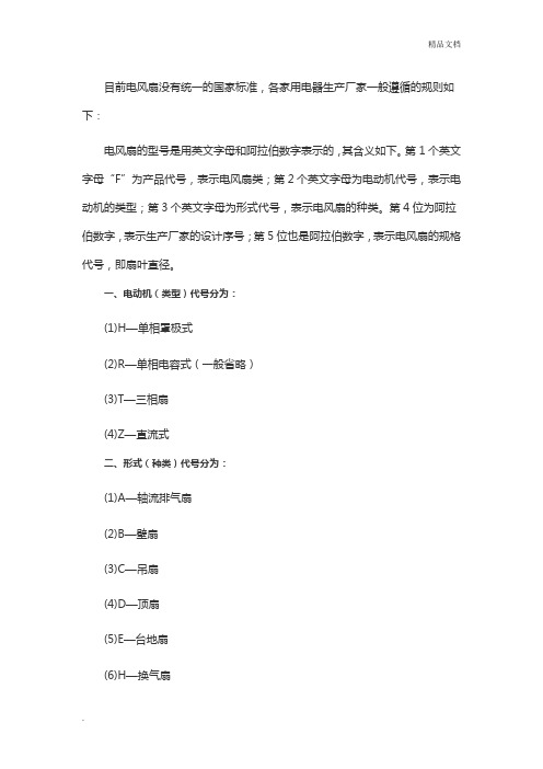
PF系列排风扇结构图 圆出风口排气扇
90°出风口排气扇
PF系列排风扇性能参数表 型 号 风 量 m3/h 电机 功率 90 90 140 140 200 200 300 300 400 400 500 500 600 600 700 700 800 800 1200 1200
w
5
5
6
10
15
20
PF系列排风扇
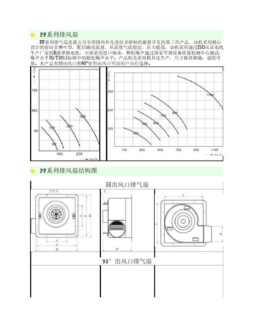
PF系列排气扇是我公司引用国内外先进技术研制的最新开发的第三代产品,该机采用精心 设计的前向多翼叶型,配以蜗壳流道,从而使气流稳定,压力提高,该机采用通过ISO认证电机 生产厂家的E级罩极电机,全部采用进口轴承,整机噪声通过国家空调设备质量检测中心测试, 噪声合乎JG/T3011标准中的超低噪声水平。产品机壳采用模具化生产,尺寸极其精确,强度可 靠。本产品有圆出风口和90°矩形出风口可由用户自行选择。
40
40
40
90
噪 声 37 dB(A) 重 量 2.4 பைடு நூலகம்g
38 2.4
39 2.4
41 4.2
43 5
45 5.2
52 8.5
53 8.5
54 8.5
56 11
PF系列排风扇装配尺寸(mm) 型 号 A B B1 F H PF90 PF140 PF200 PF300 PF400 PF500 PF600 PF700 PF800 PF1200 130 250 270 230 175 130 250 270 230 175 130 250 270 230 175 178 326 347 305 209 178 326 347 305 216 178 326 347 305 216 200 366 386 346 245 200 366 386 346 245 200 366 386 346 245 200 366 386 346 245
冷却塔百叶窗 标准

冷却塔百叶窗标准
冷却塔百叶窗是一种用于冷却塔的设备,通常由许多平行的金属叶片组成,可以调整叶片的角度以控制空气的流动和冷却效果。
以下是冷却塔百叶窗的一些标准和特点:
1. 材料:一般采用镀锌铁皮或不锈钢制作,具有耐高温、防腐蚀的特性。
2. 尺寸:冷却塔百叶窗的尺寸通常根据冷却塔的大小和要求而定,可以根据实际需求定制。
3. 叶片角度:冷却塔百叶窗的叶片角度可根据冷却需求进行调整,通常为定角度或可调角度。
4. 安装方式:冷却塔百叶窗可以直接安装在冷却塔的进风口,也可以作为附件安装。
5. 叶片数量:叶片数量的多少会影响冷却效果,一般叶片越多,则冷却效果越好。
6. 寿命:冷却塔百叶窗的寿命取决于材料质量和使用条件,一般可以使用多年。
冷却塔百叶窗的设计和选择需要综合考虑冷却塔的工作条件和要求,确保其正常运行和高效冷却。
电动百叶风口原理

电动百叶风口原理
电动百叶风口是一种能够调节室内空气流通和温湿度的装置。
它通常由一组水平或垂直排列的可调节百叶片组成。
百叶片通过电动机驱动,可根据需要进行开合调节,实现室内空气的流通和调节。
电动百叶风口的原理是利用电动机的驱动力,将能量转化为机械能,驱动百叶片的运动。
在关闭状态下,百叶片彼此靠拢,形成一个封闭的空间,阻止了室内外空气的相互交换。
而在开启状态下,百叶片张开,形成一定的通风孔,允许室内外空气通过孔隙的流通,实现空气的对流和交换。
通过电动百叶风口的开合调节,可以实现室内空气的流通和温湿度的调节。
当室内温度过高时,可通过将百叶片打开一定角度,增加室内外空气的交换,加快冷热空气的对流,达到降温的效果。
而在寒冷的冬季,可以将百叶片关闭,减少室内外空气的交换,防止冷空气的侵入,提高室内温度。
此外,百叶风口的调节还可以帮助调节室内的湿度,增加空气的新鲜度,提高人们的舒适感。
总之,电动百叶风口利用电动驱动原理实现百叶片的开合调节,从而实现室内空气的流通和温湿度的调节。
它在家庭、办公室和其他场所得到广泛应用,为人们营造一个舒适、健康的室内空气环境。
百叶窗的工作原理及百叶窗的调节方法

百叶窗的工作原理及百叶
窗的调节方法
汇报人:XX
目录
01
02
百叶窗的工作原理 百叶窗的调节方法
01
百叶窗的工作原理
百叶窗的结构
叶片:可调节角 度,控制光线进 入室内
调节杆:用于调 整叶片角度
轨道:使叶片能 够平稳移动和调 节
固定座:将百叶 窗固定在墙上
百叶窗的工作方式
通过旋转百叶窗的叶片,可 以调节叶片之间的角度,从 而调节光线的透过量
定期检查百叶窗调节装置是 否正常工作
根据需要调整叶片角度,以 达到最佳遮阳效果
感谢观看
汇报人:XX
的角度
电动调节:通 过遥控器或手 机APP控制百 叶窗的调节杆, 实现叶片角度
的自动调节
智能调节:根 据室内光线和 温度等参数, 自动调节百叶 窗的叶片角度, 实现智能化控
制
机械调节:利 用机械连杆机 构,通过旋转 调节杆实现叶 片角度的调节
02
百叶窗的调节方法
手动调节
旋转百叶窗叶片: 通过旋转叶片来 调整角度
转动角度:百叶窗的叶片可以调节不同的角度来控制光线的进入,根据需要选择合适的角度,以 达到最佳的遮阳效果。
调节方式:百叶窗的调节方式通常分为上下调节和左右调节两种,上下调节可以改变叶片与窗框 之间的夹角,左右调节则可以改变叶片的百叶窗的调节 杆,改变叶片
拉动拉绳:通过 拉绳来控制百叶 窗的升降
推拉窗框:通过 推拉窗框来调节 百叶窗的开合度
调整螺丝:通过 调整螺丝来固定 百叶窗的位置
电动调节
电动调节器控制 百叶窗的开启和 关闭
可以通过遥控器 或手机APP进行 远程控制
调节百叶窗的角 度,实现通风和 遮阳的效果
电风扇排气扇的规格和型号分类
目前电风扇没有统一的国家标准,各家用电器生产厂家一般遵循的规则如下:电风扇的型号是用英文字母和阿拉伯数字表示的,其含义如下。
第1个英文字母“F”为产品代号,表示电风扇类;第2个英文字母为电动机代号,表示电动机的类型;第3个英文字母为形式代号,表示电风扇的种类。
第4位为阿拉伯数字,表示生产厂家的设计序号;第5位也是阿拉伯数字,表示电风扇的规格代号,即扇叶直径。
一、电动机(类型)代号分为:(1)H—单相罩极式(2)R—单相电容式(一般省略)(3)T—三相扇(4)Z—直流式二、形式(种类)代号分为:(1)A—轴流排气扇(2)B—壁扇(3)C—吊扇(4)D—顶扇(5)E—台地扇(6)H—换气扇(7)Y—转叶扇(8)R—热风扇(9)S—落地扇(10)T—台扇例如,FT8-20,表示单相电容式电机台式扇,厂家第8次设计,规格为200mm;FHH1-40,表示单相罩极式换气扇,厂家第1次设计,规格为400mm。
三、吊扇的安装(美的吊扇)常用空间解决方案(吊扇安装空间说明)A、小于10平方米的空间建议安装一台吊扇。
B、两台吊扇机头圆心之间间距最少大于2.5米,最大不超过4.5米。
C、根据空间大小,可以通过以下公式计算需要的吊扇数量。
吊扇数量=(空间长度/2.5)*(空间宽度/2.5)D、吊扇安装空间使用标准换气扇的型号及命名1 换气扇的型号及命名1.1 按型式分类1.1.1 按功能分a)单向式(只有一种气流方向输送状态的换气扇);b)过滤式(对输送的气流有过滤作用的换气扇);c)双向式(通过操作变换,可以按排气状态工作,也可以按进气状态工作的换气扇);d)双向同时式(可以同时进行强迫排气和强迫进气的换气扇);e)热交换式(排气和进气气流可以在换气扇内进行热交换的换气扇)。
1.1.2 按结构分1.1.2.1 开敞式换气扇不工作时,其结构不能遮隔外界气流流经换气扇。
类似图1结构的换气扇属于开敞式。
1.1.2.2 遮隔式换气扇不工作时,其结构能遮隔外界气流流经换气扇。
fantech 浴室排风扇安装手册说明书

fantechUnited States10048 Industrial Blvd., Lenexa, KS, 66215Tel.: 800.747.1762 • Fax: 800.487.9915Canada50 Kanalflakt Way, Bouctouche, NB, E4S 3M5Tel.: 800.565.3548 • Fax: 877.747.8116BFRK100Bath Fan Retrofit KitBFRK100 Kit Includes:FG4 fan with mounting bracket, 1 pc VT 20M Main Control, 1 pc 3" to 4" adapters, 2 pcs wire connectors. 2 pcs cable restaint, 1 pc roll of duct tape, 1 pc8' flexible insulated 4" duct12' 14-2 insulated electrical wire2fantechWarningsDO NOT CONNECT POWER SUPPLY until fan is completely installed. Make sure electrical service to the fan is locked in “Off” position 1. All units are suitable for use with solid-state speed control.2. This unit has rotating parts and safety precautions should be exercised during installation, operation and maintenance.3. CAUTION : “For General Ventilation Use Only. Do Not Use To Exhaust Hazardous Or Explosive Materials And Vapors.”4. WARNING : To reduce the risk of fire, electrical shock, or injury to persons-observe the following:a. Use this unit only in the manner intended by the manufacturer. If you have questions, contact the factory.b. Before servicing or cleaning, switch power off at service panel and lock service panel to prevent fan from being switched on accidentally.c. Installation work and electrical wiring must be done by qualified person(s) in accordance with all applicable codes and standards, including fire-rated construction.d. The combustion airflow needed for safe operation of fuel burning equipment may be affected by this unit's operation. Follow the heating equipment manufacturer's guidelines and safety standards such as those published by the National Fire Protection Association (NFPA), the American Society of Heating, Refrigeration, and Air Conditioning Engineers (ASHRAE) and the local code authorities.e. When cutting or drilling into wall or ceiling, do not damage electrical wires or other hidden utilities.f. Exhaust fans must always be vented to the outdoors.g. Acceptable for use over a bathtub or shower.h. NEVER place a switch where it can be reached from a tub or shower.5. WARNING! Check voltage at the fan to see if it corresponds to the motor nameplate.GUARDS MUST BE INSTALLED WHEN FAN IS WITHIN REACH OF PERSONNEL OR WITHIN SEVEN (7) FEET OF WORKING LEVEL OR WHEN DEEMED ADVISABLE FOR SAFETY.Read and Save these instructions for future reference.Not for use with fan/light, heater/fan, or heater/fan/light combination units3fantechInstallationStep 1Switch power off at service panel and lock the service disconnecting means to prevent power from being switched on accidentally.Step 2In the bathroom, remove the inlet grille.Step 3Unplug the motor and remove the motor plate. If convenient, you maywant to remove the motor from the motor plate at this stage.The motor from your existing fan will not be used when your retrofit installation is complete. However, the motor plate may be essential for attaching the inlet grille.Step 4Remove the wiring cover of your existing ceiling mounted bath fan. Disconnect the power wires to your existing fan.Step 5Attach the flexible duct provided to the inlet port of the new fan. Tape the black inner liner to the four inch diameter lip and tape the reflective outer shell to the larger diameter shoulder. Do not leave the insulation material exposed.Step 6Electrical Connection for new fanA Remove the screws securing the terminal box cover located on the side of the fan. All fan motor connections are pre-wired to an electrical terminal strip. Use the cable restraint provided to secure the wiring through the hole on the electrical box.B Be sure to place the connector nut over the wiring coming into the electrical box. There are two open ports on the terminal strip. Using a small regular screwdriver, tighten the neutral (white) wire of the incoming supply under the open terminal strip port labeled "N". Tighten the line (black) wire of the incoming supply under the open terminal strip port labeled "L". Tighten the ground (green) wire of the incoming supply under the open terminal strip port labeled with the Ground symbol. If the terminal strip is not labeled, follow the wiring diagram found on the inside of the electrical cover.C Secure the cable restraint. Secure the incoming supply with the cable restraint. Replace the fan electrical box cover. All fan motor and capacitor connections have been pre-wired from the factory. No additional fan wiring is necessary.D The other end of the electrical cable will be connected in a later step.Step 7In the attic or crawl space, find the location of the existing bath fan and its exhaust duct. Select a location for the new FG 4 fan. The new fan will be connected to part of the existing exhaust duct so you must plan to locate the new fan along the line of the existing exhaust duct, no greater than seven feet from the existing fan. Fan location should allow sufficient access for service. For applications that require the new FG4 fan to be located more that seven feet from the existing fan, longerlengths of electrical cable and flexible insulated 4” duct can be purchased separately.Step 3Step 44fantechStep 8Using the wood screws provided, attach the mounting bracket to a support beam at the selected location. Fan mounting can be at any point along the duct and in any angle, however, vertical mounting is recommended to reduce condensation buildup in the fan. If a horizontal installation is necessary and condensation buildup may pose a problem, either wrap insulation around the fan or drill a 1/4" hole in the bottom of the housing (along with an NPT insert [by others] and drain tubing) allowing condensation to drain.Step 9Cut the existing duct 8” above the mounting bracket. Make a second cut in the duct at approximately 12” from the existing fan, and then remove this middle section of the existing duct.Step 10Attach fan to the mounting bracket with the sheet metal screws provided. Wiring box should be positioned for easy access. Screws are self tapping and do not require pilot holes. However, pilot holes (no larger than 3/32" ) are recommended.Step 11Connect the section of the existing duct (from the roof cap, wall cap or soffit vent) to the outlet port of the new fan using duct tape. If your existing exhaust duct is 3” diameter, use one of the 3” to 4” adapters (supplied in the kit).Step 12Connect the section of the existing duct (from the discharge of the existing fan) to flexible duct (from the inlet on the new fan) using duct tape. If your existing exhaust duct is 3” diameter, use one of the 3” to 4” adapters (supplied in the kit). Tape the black inner liner to the four inch diameter lip and tape the reflective outer shell over the top of the inner liner. Do not leave the insulation material exposed.Step 13Uncoil the new electrical cable from the new fan. Loosen the cable restraint on the existing fan and feed 4” of the new cable through the restraint, next to the existing electrical cable. Tighten the screws on the cable restraint of the existing fan.Step 14In the bathroom, connect the new cable to the existing power supply (black wire to black wire, white wire to white wire) using the wire nuts provided.Step 15Carefully push the new connections back into the fan housing (or wiring box within the fan housing) making sure that no wires will be pinched before putting the wiring cover and motor plate back into position. Reattach the fan grille.Step 16Install the VT20M fan controller in an electrical box upstream of the fan. See also the instructions included with the VT20M controller.Step 17Restore electrical service, switch on and verify airflowInstallation(Cont'd)Step 11 & Step 12Step 13Step 145fantechFive (5) Year WarrantyThis warranty supersedes all prior warrantiesDURING ENTIRE WARRANTY PERIOD:Fantech will repair or replace any part which has a factory defect in workmanship or material. Product may need to be returned to the Fantech factory, together with a copy of the bill of sale and identified with RMA number.FOR FACTORY RETURN YOU MUST: • H ave a Return Materials Authorization (RMA) number. This may be obtained by calling Fantech either in the USA at 1.800.747.1762 or in CANADA at 1.800.565.3548. Please have bill of sale available. • T he RMA number must be clearly written on the outside of the carton, or the carton will be refused. • A ll parts and/or product will be repaired/replaced and shipped back to buyer; no credit will be issued.ORThe Distributor may place an order for the warranty part and/or product and is invoiced. The Distributor will receive a credit equal to the invoice only after product is returned prepaid and verified to be defective.FANTECH WARRANTY TERMS DO NOT PROVIDE FOR REPLACEMENT WITHOUT CHARGE PRIOR TO INSPECTION FOR A DEFECT.REPLACEMENTS ISSUED IN ADVANCE OF DEFECT INSPECTION ARE INVOICED, AND CREDIT IS PENDING INSPECTION OF RETURNEDMATERIAL. DEFECTIVE MATERIAL RETURNED BY END USERS SHOULD NOT BE REPLACED BY THE DISTRIBUTOR WITHOUT CHARGE TO THEEND USER, AS CREDIT TO DISTRIBUTOR’S ACCOUNT WILL BE PENDING INSPECTION AND VERIFICATION OF ACTUAL DEFECT BY FANTECH.THE FOLLOWING WARRANTIES DO NOT APPLY: • D amages from shipping, either concealed or visible. Claim must be filed with freight company.• Damages resulting from improper wiring or installation. • D amages or failure caused by acts of God, or resulting from improper consumer procedures, such as: 1. Improper maintenance 2. Misuse, abuse, abnormal use, or accident, and 3. Incorrect electrical voltage or current. • R emoval or any alteration made on the Fantech label control number or date of manufacture. • A ny other warranty, expressed, implied or written, and to anyconsequential or incidental damages, loss or property, revenues, or profit, or costs of removal, installation or reinstallation, for any breach of warranty.WARRANTY VALIDATION• The user must keep a copy of the bill of sale to verify purchase date. • T hese warranties give you specific legal rights, and are subject to an applicable consumer protection legislation. You may have additional rights which vary from state to state.This warranty does not apply to any Fantech product or part which has failed as a result of faulty installation or abuse, incorrect electrical connections or alterations made by others, or use under abnormal operating conditions or misapplication of the product or parts. We will not approve for payment any repair not made by us or our authorized agent without prior written consent. The foregoing shall constitute our sole and exclusive warranty and our sole exclusive liability, and is in lieu of any other warranties, whether written, oral, implied or statutory. There are no warranties which extend beyond the description on the page hereof. In no event, whether as a result of breach of contract, orwarranty or alleged negligence, defect incorrect advice or other causes, shall Fantech be liable for special or consequential damages, including, but not limited to, loss of profits or revenue, loss of use of equipment or any other associated equipment, cost of capital, cost of substitute equipment, facilities or services, downtime costs, or claims ofcustomers of purchase for such damages. Fantech neither assumes or authorizes any person to assume for it any other liability in connection with the sale of product(s) or part(s). Some jurisdictions do not allow the exclusion or limitation of incidental or consequential damages so the above limitations and exclusions may not apply to you.Limitation of Warranty and LiabilityWarningFantech products are designed and manufactured to provide reliable performance, but they are not guaranteed to be 100% free from defects. Even reliable products will experience occasional failures and this possibility should be recognized by the user. If these products areused in a life support ventilation system where failure could result in loss or injury, the user should provide adequate backup ventilation,supplementary natural ventilation, failure alarm system, or acknowledge willingness to accept the risk of such loss or injury.Warranty6 Notesfantech7 NotesfantechFantech reserves the right to make technical changes.For updated documentation please refer to Fantech®fantech。