AT83C25OKxxx-RDTIM中文资料
MX25L8005M2C-15G中文资料
- pause the chip without diselecting the chip
• PACKAGE
- 8-pin SOP (150mil) - 8-pin SOP (200mil)
- 8-pin PDIP (300mil) - 8-land SON/WSON (6x5mm), 8-land SON is not recommended for new design - 8-land USON (4x4mm) - All Pb-free devices are RoHS Compliant
To provide user with ease of interface, a status register is included to indicate the status of the chip. The status read command can be issued to detect completion status of a program or erase operation via WIP bit.
- Serial Data Input
• SO Output
- Serial Data Output
P/N: PM1237 1
REV. 2.2, OCT. 23, 2008
元器件交易网
MX25L8005
• WP# pin
- Hardware write protection
Clock Generator
Output Buffer
SO
P/N: PM1237
REV. 2.2, OCT. 23, 2008 3
元器件交易网
MX25L8005
AT91SC25672RC资料

1FeaturesGeneral•Based on the ARM ® SC100™ SecurCore ™ 32-bit RISC Processor •Two Instruction Sets –ARM High-performance 32-bit Instruction Set –Thumb ® High-code-density 16-bit Instruction Set •4-Gbyte Linear Address Space•Von Neumann Load/Store Architecture–Single 32-bit Data Bus for Instructions and Data •3-stage Pipeline Architecture–Fetch, Decode and Execute Stages •8-bit, 16-bit, and 32-bit Data Types•On-chip Programmable System Clock up to 50 MHz •Very Low Power Consumption: –Industry Leader in MIPS/Watt–Low-power Idle and Power-down Modes •Bond Pad Locations Conforming to ISO 7816-2•ESD Protection to ± 6000V•Operating Ranges: 2.7V to 5.5V, GSM/3G Compliant, PC Industry Compatible, EMVMemory•256K Bytes of ROM Program Memory•72K Bytes of EEPROM User Memory, Including 256 OTP Bytes–Typically More than 500,000 Write/Erase Cycles •10K Bytes of RAMPeripherals•Two I/O Ports –Configurable to Support Communication Protocols, Including ISO 7816-3 and 2-wire Protocols •ISO 7816 Controller–Up to 625 kbps at 5 MHz•Serial Peripheral Interface (SPI) Controller (up to 12 MHz)•Two 16-bit Timers•Random Number Generator (RNG)•2-level, 12-vector Interrupt Controller •Hardware DES and Triple DES •Checksum Accelerator •CRC 16 / 32 Engine•32-bit Cryptographic Accelerator for Public Key Operations Including GF(2N )–RSA, DSA, ECC, Diffie-Hellman •Advanced MPU•High-performance Hardware Java Card AcceleratorSecurity•Dedicated Hardware for Protection Against SPA/DPA Attacks •Advanced Protection Against Physical Attack •Environmental Protection Systems •Voltage and Frequency Monitors•Secure Memory Management/Access ProtectionDevelopment Tools•Hardware Development Support on the ATV3-91SC Voyager Emulation Platform. Seethe ATV3-91SC Emulator Product Preview for Further Details.Note: This is a summary document. A complete document isavailable under NDA. For more information, please contact your local Atmel sales office.2AT91SC25672RC1575CS–SMIC–09/03DescriptionThe AT91SC25672RC is a low-power, high-performance, 32-bit RISC microcontroller with ROM program memory, EEPROM data memory, and cryptographic accelerator,based on the new ARM SC100 advanced secure processor. The SC100 embedded core is the first member of the ARM SecurCore family. This general-purpose 32-bit pro-cessor offers high performance, very low power consumption, and additional features to help combat fraud.The AT91SC25672RC features 72K bytes of high-performance EEPROM (fast erase/write time, high endurance). This allows system developers to offer their custom-ers a true 64K bytes EEPROM, while still being able to use the remaining 8K bytes for their own purposes (e.g. customization and patches).The cryptographic accelerator featured in the AT91SC series is the new AdvX ™. It is based on a 32-bit multiplier-accumulator architecture which is designed to perform fast encryption and authentication functions. This enables fast computation and low-power operation. The AdvX, in conjunction with controlling firmware running within the SC100core, supports standard finite fields arithmetic functions (including RSA, DSA, DH, ECC)and GF(2N ).On top of the SC100´s MPU, a real hardware firewall can be used to increase the overall security level of the application without intense software development.Unique hardware features significantly accelerate the execution of Java Card Byte Code by removing the common software bottlenecks encountered during the implementation of a Java Virtual Machine.Additional security features include power and frequency protection logic, logical scram-bling on program data and addresses, power analysis countermeasures and memory accesses controlled by a supervisor mode.Pin ConfigurationThe AT91SC25672RC pinout conforms to the ISO 7816-2 interface. It also provides a second I/O port.Note:By convention, the RST pin corresponds to the RST signal of the ISO 7816-3 Protocol.Both are active low.GND Ground (reference voltage)V CC Power supply inputI/O0Input or output for serial dataI/O1Second input or output for serial dataAlso used as Slave Select line for the SPI controller MOSI SPI Master output – Slave input MISO SPI Master input – Slave output SCK SPI ClockCLK Clock signal input to internal clock operating circuit RSTReset signal input, a low state stops the ARM core3AT91SC25672RC1575CS–SMIC–09/03Architectural OverviewThe SC100 is a 3-stage pipeline, 32-bit RISC processor. It uses a Von Neumann load/store architecture, which is characterized by a single data and address bus for instructions and data.The SC100 processor employs a unique architectural strategy known as Thumb ®, a super-reduced instruction set that is ideally suited for high-volume applications with memory restrictions, and applications where code density is an important factor. Essen-tially, the SC100 processor has two instruction sets:•The standard ARM instruction set uses 32-bit instructions and offers maximum performance.•The Thumb instruction set uses 16-bit instructions and offers maximum code density.Both instruction sets operate on 8-bit, 16-bit, and 32-bit data types.The Thumb´s 16-bit instruction length allows it to achieve almost twice the density of standard ARM code, while retaining most of the ARM´s performance advantage over a traditional 16-bit processor using 16-bit registers. This is possible because the 16-bit Thumb instructions operate on the same 32-bit register set as the 32-bit ARM instruc-tions. Thumb code can be up to 35% smaller than the equivalent ARM code, while providing 160% of the performance of an equivalent ARM processor connected to a 16-bit memory system.© Atmel Corporation 2003.Atmel Corporation makes no warranty for the use of its products, other than those expressly contained in the Company’s standard warranty which is detailed in Atmel’s Terms and Conditions located on the Company’s web site. The Company assumes no responsibility for any errors which may appear in this document, reserves the right to change devices or specifications detailed herein at any time without notice, and does not make any commitment to update the information contained herein. No licenses to patents or other intellectual property of Atmel are granted by the Company in connection with the sale of Atmel products, expressly or by implication. Atmel’s products are not authorized for use as critical components in life support devices or systems.Atmel HeadquartersAtmel OperationsCorporate Headquarters2325 Orchard Parkway San Jose, CA 95131TEL 1(408) 441-0311FAX 1(408) 487-2600EuropeAtmel SarlRoute des Arsenaux 41Case Postale 80CH-1705 Fribourg SwitzerlandTEL (41) 26-426-5555FAX (41) 26-426-5500AsiaRoom 1219Chinachem Golden Plaza 77 Mody Road Tsimhatsui East Kowloon Hong KongTEL (852) 2721-9778FAX (852) 2722-1369Japan9F, Tonetsu Shinkawa Bldg.1-24-8 ShinkawaChuo-ku, Tokyo 104-0033JapanTEL (81) 3-3523-3551FAX (81) 3-3523-7581Memory2325 Orchard Parkway San Jose, CA 95131TEL 1(408) 441-0311FAX 1(408) 436-4314Microcontrollers2325 Orchard Parkway San Jose, CA 95131TEL 1(408) 441-0311FAX 1(408) 436-4314La Chantrerie BP 7060244306 Nantes Cedex 3, France TEL (33) 2-40-18-18-18FAX (33) 2-40-18-19-60ASIC/ASSP/Smart CardsZone Industrielle13106 Rousset Cedex, France TEL (33) 4-42-53-60-00FAX (33) 4-42-53-60-011150 East Cheyenne Mtn. Blvd.Colorado Springs, CO 80906TEL 1(719) 576-3300FAX 1(719) 540-1759Scottish Enterprise Technology Park Maxwell BuildingEast Kilbride G75 0QR, Scotland TEL (44) 1355-803-000FAX (44) 1355-242-743RF/AutomotiveTheresienstrasse 2Postfach 353574025 Heilbronn, Germany TEL (49) 71-31-67-0FAX (49) 71-31-67-23401150 East Cheyenne Mtn. Blvd.Colorado Springs, CO 80906TEL 1(719) 576-3300FAX 1(719) 540-1759Biometrics/Imaging/Hi-Rel MPU/High Speed Converters/RF DatacomAvenue de Rochepleine BP 12338521 Saint-Egreve Cedex, France TEL (33) 4-76-58-30-00FAX (33) 4-76-58-34-80e-mailliterature@Web Site1575CS–SMIC–09/03 xMATMEL ® is the registered trademark of Atmel; AdvX ™ is the trademark of Atmel.ARM ®, Thumb ®, and ARM Powered ® are the registered trademarks of ARM Ltd. SC100™ and SecurCore ™ are the trademarks of ARM Ltd. Other terms and product names may be the trademarks of others.。
ATSTK525;中文规格书,Datasheet资料
STK525 ............................................................................................. Hardware User GuideSection 1 Introduction...........................................................................................1-31.1Overview...................................................................................................1-31.2STK525 Starter Kit Features.....................................................................1-4Section 2Using the STK525.................................................................................2-62.1Overview...................................................................................................2-62.2Power Supply............................................................................................2-72.3RESET....................................................................................................2-102.4AT90USBxxx AVR Microcontroller..........................................................2-112.5Serial Links.............................................................................................2-112.6On-board Resources...............................................................................2-142.7STK500 Resources.................................................................................2-192.8In-System Programming.........................................................................2-202.10Test Points..............................................................................................2-232.11Configuration Pads.................................................................................2-242.12Solder Pads............................................................................................2-25Section 3Troubleshooting Guide.......................................................................3-26 Section 4Technical Specifications.....................................................................4-27Section 5Technical Support...............................................................................5-28Section 6Complete Schematics.........................................................................6-29Section 1IntroductionCongratulation for acquiring the AVR® STK525 Starter Kit. This kit is designed to givedesigners a quick start to develop code on the AT90USBxxx and for prototyping andtesting of new designs.1.1OverviewThis document describes the STK525 dedicated to the AT90USBxxx AVRmicrocontroller. This board is designed to allow an easy evaluation of the product usingdemonstration software.To complement the evaluation and enable additional development capability, theSTK525 can be plugged into the Atmel STK500 Starter Kit Board in order to use theAT90USBxxx with advanced features such as variable VCC, variable VRef, variableXTAL, etc. and supports all AVR development tools.To increase its demonstrative capabilities, this stand alone board has numerous on-board resources (USB, RS232, joystick, data-flash, microphone and temperaturesensor).This user guide acts as a general getting started guide as well as a complete technicalreference for advanced users.IntroductionFigure 1-1 . STK525 Board1.2STK525 Starter Kit FeaturesThe STK525 provides the following features:AT90USBxxx TQFP device (2.7V<Vcc<5.5V),AVR Studio® software interface (1),USB software interface for Device Firmware Upgrade (DFU bootloader) (2)STK500 compatiblePower supply flagged by “VCC-ON” LED:–regulated 3 or 5V,–from an external power connector,–from the USB interface (USB device bus powered application),–from STK500 (2),ISP connector for on-chip ISP,JTAG connector:–for on-chip ISP,–for on-chip debugging using JTAG ICE,Serial interfaces:– 1 USB full/low speed device/host interface–RS-232C ports with RTS/CTS handshake lines,On-board resources:–4+1-ways joystick,–4LEDs,–temperature sensor,–microphone,–serial dataflash memory,IntroductionOn-board RESET button,On-board HWB button for force bootloader section execution at reset.System clock:–external clock from STK500 expand connectors–8 MHz crystal,Numerous access points for test.Notes: 1.The STK525 is supported by AVR Studio®, version 4.12SP2 or higher. For up-to-date information on this and other AVR tool products, please consult our web site. Thenewest version of AVR Studio®, AVR tools and this User Guide can be found in theAVR section of the Atmel web site, .2.ATMEL Flip®, In System Programming Version 3 or Higher shall be used for DeviceFirmware Upgrade. Please consult Atmel web site to retrieve the latest version of Flipand the DFU bootloader Hex file if needed.Section 2Using the STK525This chapter describes the board and all its features.2.1OverviewFigure 2-1 . STK525 OverviewUSB MiniABRS232JTAGISPExternal PowerJoystick PotentiometerResetCrystal Microphone S T K 500 E x p a n d 0S T K 500 E x p a n d 1Data FlashLEDSVcc Src.SettingTQFP64 SocketPin1C SensorVbus Gen.SettingBootloader ActivationUsing the STK5252.2Power SupplyThe on-board power supply circuitry allows various power supply configurations.2.2.1Power Supply SourcesThe power supply source can come from three different (3) and exclusive sources: USB connector,JACK PWR connector (J6, See Figure 2-2), STK500USB powered:When used as a USB device bus powered application, the STK525 can be powered viathe USB VBUS power supply line.JACK PWR connector:–Need of a male JACK outlet,–Input supply from 9 up to 15V (1) DC,–No specific polarization (2) is required.Figure 2-2 . JACK PWR Connector (J6)Figure 2-3 . Male JACK Outlet and WiresSTK500 Powered:(c.f. “STK500 Resources” on page 19).Notes:1.15V is the maximum level limitation of an unidirectional transit diode.2.There is a diode (bridge) voltage level between the negative output of the powersupply and the STK525 “GND”. This could introduce some gap of voltage during measurement and instrumentation.3.Caution : Do not mount more than onepower supply source on STK525.Using the STK5252.2.2Power Supply SettingTable 2-1 . Power Supply (1) SettingNotes: 1.Caution: The STK500 has its own “ON/OFF” switchUsing the STK525 2.2.3VBUS Generator SettingWhen using the AT90USBxxx microcontroller in USB host mode. The STK525 shouldprovide a 5V power supply over the VBUS pin of its USB mini AB connector.A couple of transistors on the STK525 allows the UVCON pin of the AT90USBxxx tocontrol the VBUS generation (See Figure2-4). In this mode the STK525 is powered byexternal power supply source (J6 or STK500 expand0/1 connectors). JP7 allows toselect the 5V source used by the VBUS generator.Figure 2-4 . VBUS generator schematicTable 2-2 . VBUS Generator SettingUsing the STK5252.2.4“POWER-ON“ LEDThe POWER-ON LED is always lit when power is applied to STK525 regardless ofpower supply source and the regulation.Figure 2-5 . “VCC-ON” LED2.3RESETAlthough the AT90USBxxx has its on-chip RESET circuitry (c.f. AT90USBxxxDatasheet, section “System Control and Reset), the STK525 provides the AT90USBxxxa RESET signal which can come from 3 different sources:2.3.1Power-on RESETThe on-board RC network acts as power-on RESET.2.3.2RESET Push ButtonBy pressing the RESET push button on the STK525, a warm RESET of theAT90USBxxx is performed.Figure 2-6 . RESET Push Button (RST) Implementation分销商库存信息: ATMELATSTK525。
MAX825中文资料
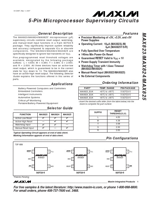
_______________General DescriptionThe MAX823/MAX824/MAX825* microprocessor (µP)supervisory circuits combine reset output, watchdog,and manual-reset input functions in a 5-pin SOT23-5package. They significantly improve system reliability and accuracy compared to separate ICs or discrete components. The MAX823/MAX824/MAX825 are specifically designed to ignore fast transients on V CC .Five preprogrammed reset threshold voltages are available, designated by the following package suffixes: L = 4.63V, M = 4.38V, T = 3.08V, S = 2.93V,and R = 2.63V. All three devices have an active-low reset output, which is guaranteed to be in the correct state for V CC down to 1V. The MAX824/MAX825 also have an active-high reset output. The following Selector Guide explains the functions offered in this series of parts.________________________ApplicationsBattery-Powered Computers and Controllers Embedded Controllers Intelligent Instruments Automotive Systems Critical µP MonitoringPortable/Battery-Powered Equipment____________________________Featureso Precision Monitoring of +3V, +3.3V, and +5V Power Supplies o Operating Current: 10µA (MAX823L/M)3µA (MAX825T/S/R)o Fully Specified Over Temperature o 140ms Min Power-On Reseto Guaranteed RESET Valid to V CC = 1V o Power-Supply Transient Immunity o Watchdog Timer with 1.6sec Timeout (MAX823/MAX824)o Manual-Reset Input (MAX823/MAX825)o No External ComponentsMAX823/MAX824/MAX8255-Pin Microprocessor Supervisory Circuits________________________________________________________________Maxim Integrated Products1__________________________________________________________Pin Configurations_____________________Selector Guide19-0487; Rev 1; 6/97______________Ordering Information†Insert the desired suffix letter (from the table below) into the blank to complete the part number.For free samples & the latest literature: , or phone 1-800-998-8800.For small orders, phone 408-737-7600 ext. 3468.Typical Operating Circuit appears at end of data sheet.Marking Information appears at end of data sheet.*Patents PendingM A X 823/M A X 824/M A X 8255-Pin Microprocessor Supervisory Circuits 2_______________________________________________________________________________________ABSOLUTE MAXIMUM RATINGSELECTRICAL CHARACTERISTICS(V CC = +4.75V to +5.5V for MAX82_L, V CC = +4.5V to +5.5V for MAX82_M, V CC = +3.15V to +3.6V for MAX82_T, V CC = +3V to +3.6V for MAX82_S, V CC = +2.7V to +3.6V for MAX82_R, T A = T MIN to T MAX , unless otherwise noted. Typical values are at T A = +25°C.) (Note 1)Stresses beyond those listed under “Absolute Maximum Ratings” may cause permanent damage to the device. These are stress ratings only, and functional operation of the device at these or any other conditions beyond those indicated in the operational sections of the specifications is not implied. Exposure to absolute maximum rating conditions for extended periods may affect device reliability.V CC ........................................................................-0.3V to +6.0V All Other Pins..............................................-0.3V to (V CC + 0.3V)Input Current, All Pins Except RESET and RESET ..............20mA Output Current, RESET, RESET ..........................................20mA Rate of Rise, V CC ............................................................100V/µs Continuous Power Dissipation (T A = +70°C)SOT23-5 (derate 7.1mW/°C above +70°C)...................571mWOperating Temperature RangeMAX82_EUK.....................................................-40°C to +85°C Storage Temperature Range.............................-65°C to +160°C Lead Temperature (soldering, 10sec).............................+300°CELECTRICAL CHARACTERISTICS (continued)(V CC= +4.75V to +5.5V for MAX82_L, V CC= +4.5V to +5.5V for MAX82_M, V CC= +3.15V to +3.6V for MAX82_T, V CC= +3V to +3.6V for MAX82_S, V CC= +2.7V to +3.6V for MAX82_R, T A= T MIN to T MAX, unless otherwise noted. Typical values are at T A= +25°C.) (Note 1)Note 1:Over-temperature limits are guaranteed by design and not production tested.Note 2:The RESET short-circuit current is the maximum pull-up current when RESET is driven low by a µP bidirectional reset pin. Note 3:WDI is internally serviced within the watchdog period if WDI is left unconnected.Note 4:The WDI input current is specified as the average input current when the WDI input is driven high or low. The WDI input is designed to drive a three-stated-output device with a 10µA maximum leakage current and a maximum capacitive load of200pF. This output device must be able to source and sink at least 200µA when active.MAX823/MAX824/MAX8255-Pin Microprocessor Supervisory Circuits _______________________________________________________________________________________3M A X 823/M A X 824/M A X 8255-Pin Microprocessor Supervisory Circuits 4_________________________________________________________________________________________________________________________________Typical Operating Characteristics(MAX823L, V CC = +5V, T A = +25°C, unless otherwise noted.)12.57.5-40-2040100V CC SUPPLY CURRENT vs. TEMPERATURE8.58.09.011.512.0M A X 823/4/5-01TEMPERATURE (°C)S U P P L Y C U R R E N T (µA )020806010.511.09.510.0250150-40-2040100RESET TIMEOUT PERIOD vs. TEMPERATURE170160180230240M A X 823/4/5-02TEMPERATURE (°C)R E S E T T I M E O U T P E R I O D (m s )020806021022019020030-40-2040100RESET COMPARATOR PROPAGATION DELAYvs. TEMPERATURE525TEMPERATURE (°C)P R O P A G A T I O N D E L A Y (µs )02080602010152.01.0-40-2040100WATCHDOG TIMEOUT PERIODvs. TEMPERATURE1.21.11.31.81.9M A X 823/4/5-04TEMPERATURE (°C)W A T C H D O G T I M E O U T P E R I O D (s e c )2080601.61.71.41.5 1.060.940.960.981.001.021.04-40-2040100NORMALIZED RESET THRESHOLD VOLTAGE vs. TEMPERATUREM A X 823/4/5-05TEMPERATURE (°C)N O R M A L I Z E D R E S E T T H R E S H O L D (V )020806002040 60 80 10012014016040100200180120140160MAXIMUM V CC TRANSIENT DURATION vs. RESET THRESHOLD OVERDRIVERESET THRESHOLD OVERDRIVE (mV), V RST - V CCT R A N S I E N T D U R A T I O N (µs )208060MAX823/MAX824/MAX8255-Pin Microprocessor Supervisory Circuits_______________________________________________________________________________________5______________________________________________________________Pin DescriptionFigure 1. Functional DiagramM A X 823/M A X 824/M A X 8255-Pin Microprocessor Supervisory Circuits 6______________________________________________________________________________________________________Detailed DescriptionRESET OutputA microprocessor’s (µP’s) reset input starts the µP in a known state. The MAX823/MAX824/MAX825 µP super-visory circuits assert a reset to prevent code-execution errors during power-up, power-down, and brownout conditions. RESET is guaranteed to be a logic low for V CC down to 1V. Once V CC exceeds the reset thresh-old, an internal timer keeps RESET low for the specified reset timeout period (t RP ); after this interval, RESET returns high (Figure 2).If a brownout condition occurs (V CC dips below the reset threshold), RESET goes low. Each time RESET is asserted it stays low for the reset timeout period. Any time V CC goes below the reset threshold the internal timer restarts. RESET both sources and sinks current.RESET on the MAX824/MAX825 is the inverse of RESET .Manual-Reset Input (MAX823/MAX825)Many µP-based products require manual-reset capabili-ty, allowing the operator, a test technician, or external logic circuitry to initiate a reset. On the MAX823/MAX825, a logic low on MR asserts reset. Reset remains asserted while MR is low, and for t RP (200ms nominal)after it returns high. MR has an internal 52k Ωpull-up resistor, so it can be left open if not used. This input can be driven with CMOS-logic levels or with open-drain/collector outputs. Connect a normally open momentary switch from MR to GND to create a manual-reset func-tion; external debounce circuitry is not required. If MR is driven from long cables or the device is used in a noisy environment, connect a 0.1µF capacitor from MR to GND to provide additional noise immunity.Watchdog Input (MAX823/MAX824)In the MAX823/MAX824, the watchdog circuit monitors the µP’s activity. If the µP does not toggle the watchdog input (WDI) within t WD (1.6sec), reset asserts. The inter-nal 1.6sec timer is cleared by either a reset pulse or by toggling WDI, which detects pulses as short as 50ns.While reset is asserted, the timer remains cleared and does not count. As soon as reset is released, the timer starts counting (Figure 3).Disable the watchdog function by leaving WDI uncon-nected or by three-stating the driver connected to WDI.The watchdog input is internally driven low during the first 7/8 of the watchdog timeout period and high for the last 1/8 of the watchdog timeout period. When WDI is left unconnected, this internal driver clears the 1.6sec timer every 1.4sec. When WDI is three-stated or uncon-nected, the maximum allowable leakage current is 10µA and the maximum allowable load capacitance is 200pF.__________Applications InformationWatchdog Input CurrentThe MAX823/MAX824 WDI inputs are internally driven through a buffer and series resistor from the watchdog counter (Figure 1). When WDI is left unconnected, the watchdog timer is serviced within the watchdog timeout period by a low-high-low pulse from the counter chain.For minimum watchdog input current (minimum overall power consumption), leave WDI low for the majority of the watchdog timeout period, pulsing it low-high-low once within the first 7/8 of the watchdog timeout period to reset the watchdog timer. If WDI is externally driven high for the majority of the timeout period, up to 160µA can flow into WDI.Figure 2. Reset Timing Diagram Figure 3. MAX823/MAX824 Watchdog Timing RelationshipInterfacing to µPs with Bidirectional Reset PinsThe RESET output maximum pull-up current is 800µA for L/M versions (400µA for T/S/R versions). This allows µPs with bidirectional resets, such as the 68HC11, to force RESET low when the MAX823/MAX824/MAX825are pulling RESET high (Figure 4).Negative-Going V CC TransientsThese supervisors are relatively immune to short-duration, negative-going V CC transients (glitches), which usually do not require the entire system to shut down.Resets are issued to the µP during power-up, power-down, and brownout conditions.The Typical Operating Characteristics show a graph of the MAX823L’s Maximum V CC Transient Duration vs.Reset Threshold Overdrive, for which reset pulses are not generated. The graph was produced using nega-tive-going V CC pulses, starting at 5V and ending below the reset threshold by the magnitude indicated (reset threshold overdrive). The graph shows the maximum pulse width that a negative-going V CC transient can typically have without triggering a reset pulse. As the amplitude of the transient increases (i.e., goes farther below the reset threshold), the maximum allowable pulse width decreases. Typically, a V CC transient that goes 100mV below the reset threshold and lasts for 15µs or less will not trigger a reset pulse.An optional 0.1µF bypass capacitor mounted close to V CC provides additional transient immunity.Watchdog Software Considerations(MAX823/MAX824)One way to help the watchdog timer monitor software execution more closely is to set and reset the watchdog input at different points in the program, rather than pulsing the watchdog input high-low-high or low-high-low. This technique avoids a stuck loop, in which the watchdog timer would continue to be reset inside the loop, keeping the watchdog from timing out.Figure 5 shows an example of a flow diagram where the I/O driving the watchdog input is set high at the begin-ning of the program, set low at the beginning of every subroutine or loop, then set high again when the pro-gram returns to the beginning. If the program should hang in any subroutine, the problem would quickly be corrected, since the I/O is continually set low and the watchdog timer is allowed to time out, causing a reset or interrupt to be issued. As described in the Watchdog Input Current section, this scheme results in higher time average WDI input current than does leaving WDI low for the majority of the timeout period and periodically pulsing it low-high-low.MAX823/MAX824/MAX8255-Pin Microprocessor Supervisory Circuits_______________________________________________________________________________________7Figure 4. Interfacing to µPs with Bidirectional Resets Figure 5. Watchdog Flow DiagramM A X 823/M A X 824/M A X 8255-Pin Microprocessor Supervisory Circuits Maxim cannot assume responsibility for use of any circuitry other than circuitry entirely embodied in a Maxim product. No circuit patent licenses are implied. Maxim reserves the right to change the circuitry and specifications without notice at any time.8____________________Maxim Integrated Products, 120 San Gabriel Drive, Sunnyvale, CA 94086 408-377-7600©1997 Maxim Integrated ProductsPrinted USAis a registered trademark of Maxim Integrated Products.__________Typical Operating Circuit___________________Chip Information______________Package InformationTRANSISTOR COUNT: 607。
AT89C2051中文资料

AT89C2051中文资料特性:·与MCS-51产品兼容·2K字节可重编程闪存-耐久性:1000次读/写周期·工作电压2.7V至V·全静态运行:0Hz至24MHz·两级程序锁存·128×8位内部RAM·15个可编程I/O口·两个16位定时器/计数器·六个中断源·可编程串行UART(= Universal Asynchronous Receiver Transmitter通用异步收发器)通道·可直接驱动LED的输出·芯片级模仿比较器·低功耗空闲模式和微功耗模式(Power-down mode)说明A T89C2051是一种低电压、高性能的8位CMOS微型计算机。
带2K字节的闪存和可擦可编程只读存储器(EPROM)。
该器件应用爱特美尔(Atmel)的高密度非易失性技术生产,与工业级MCS51架构组相兼容。
将一片通用的8位CPU与闪存集成在单块芯片上,爱特美尔A T89C2051是一种功能强盛的微型计算机。
它为许多嵌入式控制提供了高灵活性低成本的解决方案。
A T89C2051的标准特性如下:2K字节闪存,128字节RAM,15个I/O口,两个16位定时器/计数器,一个五失量两级中断结构,一个全双工串行通信口,一个精准模拟比较器,芯片级振荡器和时钟电路。
另外,A T89C2051用静态逻辑设计,可在低至零频下工作,支持两种软件可选节能模式。
空闲模式下CPU不工作,而RAM,定时器/计数器,串口和中断系统继承工作。
微功耗模式(power-down mode)下保存RAM的内容,但冻结振荡器,禁止其它所有的芯片功能直到下一个硬件复位到来。
特定指令的限制A T89C2051是爱特美尔微控制器家族中经济划算的一款产品。
它包含2K字节的闪速程度存储器。
它与MCS-51架构完全兼容,并且可以使用MCS-51指令组来编程。
8155中文资料
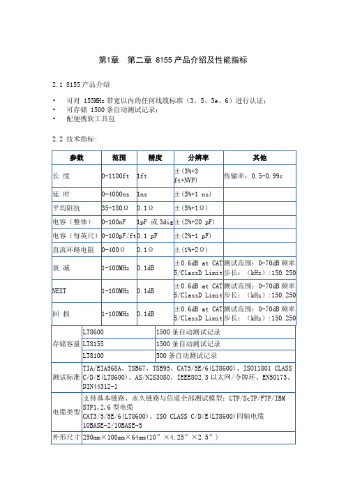
第1章第二章 8155产品介绍及性能指标2.1 8155产品介绍•可对 155MHz带宽以内的任何线缆标准(3、5、5e、6)进行认证;•可存储 1500条自动测试记录;•配便携软工具包2.2 技术指标:2.3 光纤测试选件·适用于LT8155/LT8600·可测多模和单模光纤系统的衰减值;·支持多种连接器类型·自动测试多种波长;·产生用于多模光纤的850nm和1300nm激光;·产生用于单模光纤的1310nm和1550nm激光;·测试结果可按测试方向、测试结果和工程名称进行分析保存·可用LT-Record Manager管理、分析软件存储并输出测试结果2.4 光纤选件技术指标第2章第三章 8155芯片结构3.1 8155的结构和引脚8155有40个引脚,采用双列直插封装,其引脚图和组成框图如图所示。
(1) 地址/数据线AD0~AD7(8条)(2) I/O口总线(22条):PA0~PA7、PB0~PB7、 PC0~PC5。
(3) 控制总线(8条)ALE ——地址锁存(输入)IO / /M—— IO口/RAM选择, 0:选内RAM; 1:选内IO口/CE ——片选线/RD、/WR ——读、写控制TIMERIN ——定时器输入(输入定时器所需时钟)TIMEROUT ——定时器输出(输出所产生的方波脉冲)3.2 8155的RAM和I / O口地址编码3.3 8155的工作方式与基本操作有三种基本操作:1、作单片机片外256B数据存储器IO / /M = 0,与其它数据存储器统一编址。
用MOVX访问。
2、作扩展I / O口使用IO / /M = 1,PA口、PB口、PC口,可通过编程决定如何使用。
1)命令寄存器(命令控制字)—— I / O口工作方式I / O口工作方式有四种:A口、B口基本I / O口, C口输入;A口、B口基本I / O口, C口输出;A口选通I / O、B口基本I / O、C口作联络线;A口、B口选通I / O、C口作联络线。
AT89S8253_07中文资料

1Features•Compatible with MCS ®-51 Products•12K Bytes of In-System Programmable (ISP) Flash Program Memory –SPI Serial Interface for Program Downloading –Endurance: 10,000 Write/Erase Cycles •2K Bytes EEPROM Data Memory–Endurance: 100,000 Write/Erase Cycles •64-byte User Signature Array • 2.7V to 5.5V Operating Range•Fully Static Operation: 0 Hz to 24 MHz •Three-level Program Memory Lock •256 x 8-bit Internal RAM •32 Programmable I/O Lines •Three 16-bit Timer/Counters •Nine Interrupt Sources•Enhanced UART Serial Port with Framing Error Detection and Automatic Address Recognition•Enhanced SPI (Double Write/Read Buffered) Serial Interface •Low-power Idle and Power-down Modes •Interrupt Recovery from Power-down Mode •Programmable Watchdog Timer •Dual Data Pointer •Power-off Flag•Flexible ISP Programming (Byte and Page Modes)–Page Mode: 64 Bytes/Page for Code Memory, 32 Bytes/Page for Data Memory •Four-level Enhanced Interrupt Controller•Programmable and Fuseable x2 Clock Option •Internal Power-on Reset•42-pin PDIP Package Option for Reduced EMC EmissionDescriptionThe AT89S8253 is a low-power, high-performance CMOS 8-bit microcontroller with 12K bytes of In-System Programmable (ISP) Flash program memory and 2K bytes of EEPROM data memory. The device is manufactured using Atmel’s high-density non-volatile memory technology and is compatible with the industry-standard MCS-51instruction set and pinout. The on-chip downloadable Flash allows the program mem-ory to be reprogrammed in-system through an SPI serial interface or by a conventional nonvolatile memory programmer. By combining a versatile 8-bit CPU with download-able Flash on a monolithic chip, the Atmel AT89S8253 is a powerful microcontroller which provides a highly-flexible and cost-effective solution to many embedded control applications.The AT89S8253 provides the following standard features: 12K bytes of In-System Pro-grammable Flash, 2K bytes of EEPROM, 256 bytes of RAM, 32 I/O lines,programmable watchdog timer, two data pointers, three 16-bit timer/counters, a six-vector, four-level interrupt architecture, a full duplex serial port, on-chip oscillator, and clock circuitry. In addition, the AT89S8253 is designed with static logic for operation down to zero frequency and supports two software selectable power saving modes.The Idle Mode stops the CPU while allowing the RAM, timer/counters, serial port, and interrupt system to continue functioning. The Power-down mode saves the RAM con-tents but freezes the oscillator, disabling all other chip functions until the next external interrupt or hardware reset.The on-board Flash/EEPROM is accessible through the SPI serial interface. Holding RESET active forces the SPI bus into a serial programming interface and allows the program memory to be written to or read from, unless one or more lock bits have been activated.2AT89S8253 [Preliminary]3286A–MICRO–7/04Pin ConfigurationsPDIPTQFPPLCCPDIP3AT89S8253 [Preliminary]3286A–MICRO–7/04Pin DescriptionVCC Supply voltage (all packages except 42-PDIP).GND Ground (all packages except 42-PDIP; for 42-PDIP GND connects only the logic core and the embedded program/data memories).VDD Supply voltage for the 42-PDIP which connects only the logic core and the embedded pro-gram/data memories.PWRVDDSupply voltage for the 42-PDIP which connects only the I/O Pad Drivers.The application board must connect both VDD and PWRVDD to the board supply voltage.PWRGNDGround for the 42-PDIP which connects only the I/O Pad Drivers. PWRGND and GND are weakly connected through the common silicon substrate, but not through any metal links. The application board must connect both GND and PWRGND to the board ground.Port 0Port 0 is an 8-bit open drain bi-directional I/O port. As an output port, each pin can sink six TTL inputs. When 1s are written to port 0 pins, the pins can be used as high-impedance inputs. Port 0 can also be configured to be the multiplexed low-order address/data bus during accesses to external program and data memory. In this mode, P0 has internal pull-ups.Port 0 also receives the code bytes during Flash programming and outputs the code bytes during program verification. External pull-ups are required during program verification.Port 1Port 1 is an 8-bit bi-directional I/O port with internal pull-ups. The Port 1 output buffers can sink/source six TTL inputs. When 1s are written to Port 1 pins, they are pulled high by the weak internal pull-ups and can be used as inputs. As inputs, Port 1 pins that are externally being pulled low will source current (I IL ,150 µA typical) because of the weak internal pull-ups. Some Port 1 pins provide additional functions. P1.0 and P1.1 can be configured to be the timer/counter 2 external count input (P1.0/T2) and the timer/counter 2 trigger input (P1.1/T2EX), respectively.Furthermore, P1.4, P1.5, P1.6, and P1.7 can be configured as the SPI slave port select, data input/output and shift clock input/output pins as shown in the following table.Port 1 also receives the low-order address bytes during Flash programming and verification.Port Pin Alternate FunctionsP1.0T2 (external count input to Timer/Counter 2), clock-outP1.1T2EX (Timer/Counter 2 capture/reload trigger and direction control)P1.4SS (Slave port select input)P1.5MOSI (Master data output, slave data input pin for SPI channel)P1.6MISO (Master data input, slave data output pin for SPI channel)P1.7SCK (Master clock output, slave clock input pin for SPI channel)4AT89S8253 [Preliminary]3286A–MICRO–7/04Port 2Port 2 is an 8-bit bi-directional I/O port with internal pull-ups. The Port 2 output buffers can sink/source six TTL inputs. When 1s are written to Port 2 pins, they are pulled high by the weak internal pull-ups and can be used as inputs. As inputs, Port 2 pins that are externally being pulled low will source current (I IL ,150 µA typical) because of the weak internal pull-ups.Port 2 emits the high-order address byte during fetches from external program memory and during accesses to external data memory that use 16-bit addresses (MOVX @ DPTR). In this application, Port 2 uses strong internal pull-ups when emitting 1s. During accesses to external data memory that use 8-bit addresses (MOVX @ RI), Port 2 emits the contents of the P2Special Function Register.Port 2 also receives the high-order address bits and some control signals during Flash programming and verification.Port 3Port 3 is an 8-bit bi-directional I/O port with internal pull-ups. The Port 3 output buffers can sink/source six TTL inputs. When 1s are written to Port 3 pins, they are pulled high by the weak internal pull-ups and can be used as inputs. As inputs, Port 3 pins that are externally being pulled low will source current (I IL ,150 µA typical) because of the weak internal pull-ups.Port 3 receives some control signals for Flash programming and verification.Port 3 also serves the functions of various special features of the AT89S8253, as shown in the following table.Note:1.All pins in ports 1 and 2 and almost all pins in port 3 (the exceptions are P3.2 INT0 and P3.3INT1) have their weak internal pull-ups disabled in the Power-down mode. Port pins P3.2(INT0) and P3.1 (INT1) are active even in Power-down mode (to be able to sense an interrupt request to exit the Power-down mode) and as such still have their weak internal pull-ups turned on.RST Reset input. A high on this pin for at least two machine cycles while the oscillator is running resets the device.(on its falling edge) during accesses to external memory. This pin is also the program pulse In normal operation, ALE is emitted at a constant rate of 1/6 the oscillator frequency and may be used for external timing or clocking purposes. Note, however, that one ALE pulse is skipped during each access to external data memory.Port Pin Alternate Functions P3.0RXD (serial input port)P3.1TXD (serial output port)P3.2INT0 (external interrupt 0)(1)P3.3INT1 (external interrupt 1)(1)P3.4T0 (timer 0 external input)P3.5T1 (timer 1 external input)P3.6WR (external data memory write strobe)P3.7RD (external data memory read strobe)5AT89S8253 [Preliminary]3286A–MICRO–7/04If desired, ALE operation can be disabled by setting bit 0 of the AUXR SFR at location 8EH.With the bit set, ALE is active only during a MOVX or MOVC instruction. Otherwise, the pin is weakly pulled high. Setting the ALE-disable bit has no effect if the microcontroller is in external execution mode.to external data memory.code from external program memory locations starting at 0000H up to FFFFH. Note, however,CC for internal program executions. This pin also receives the 12-volt programming enable voltage (V PP ) during Flash programming when 12-volt program-ming is selected.XTAL1Input to the inverting oscillator amplifier and input to the internal clock operating circuit.XTAL2Output from the inverting oscillator amplifier.6AT89S8253 [Preliminary]3286A–MICRO–7/04Block Diagram7AT89S8253 [Preliminary]3286A–MICRO–7/04Special Function RegistersA map of the on-chip memory area called the Special Function Register (SFR) space is shown in Table 1.Note that not all of the addresses are occupied, and unoccupied addresses may not be imple-mented on the chip. Read accesses to these addresses will generally return random data, and write accesses will have an indeterminate effect.User software should not write 1s to these unlisted locations, since they may be used in future products to invoke new features. In that case, the reset or inactive values of the new bits will always be 0.Note:# means: 0 after cold reset and unchanged after warm reset.Table 1. AT89S8253 SFR Map and Reset Values0F8H 0FFH 0F0H B 000000000F7H 0E8H 0EFH 0E0H ACC 000000000E7H 0D8H 0DFH 0D0H PSW 00000000SPCR 000001000D7H 0C8H T2CON 00000000T2MOD XXXXXX00RCAP2L 00000000RCAP2H 00000000TL200000000TH2000000000CFH 0C0H 0C7H 0B8H IP XX000000SADEN 000000000BFH 0B0H P311111111IPH XX0000000B7H 0A8H IE 0X000000SADDR 00000000SPSR 000XXX000AFH 0A0H P211111111WDTRST (Write Only)WDTCON 0000 00000A7H 98H SCON 00000000SBUF XXXXXXXX9FH 90H P111111111EECON XX00001197H 88H TCON 00000000TMOD 00000000TL000000000TL100000000TH000000000TH100000000AUXR XXXXXXX0CLKREG XXXXXXX08FH 80HP011111111SP 00000111DP0L 00000000DP0H 00000000DP1L 00000000DP1H 00000000SPDR ########PCON 0XXX000087H8AT89S8253 [Preliminary]3286A–MICRO–7/04Auxiliary RegisterThe AUXR Register contains a single active bit called DISALE.Clock RegisterThe CLKREG register contains a single active bit called X2.SPI RegistersControl and status bits for the Serial Peripheral Interface are contained in registers SPCR (see Table 11 on page 25) and SPSR (see Table 12 on page 26). The SPI data bits are contained in the SPDR register. In normal SPI mode, writing the SPI data register during serial data transfer sets the Write Collision bit (WCOL) in the SPSR register. In enhanced SPI mode, the SPDR is also write double-buffered because WCOL works as a Write Buffer Full Flag instead of being a collision flag. The values in SPDR are not changed by Reset.Interrupt RegistersThe global interrupt enable bit and the individual interrupt enable bits are in the IE register. In addition, the individual interrupt enable bit for the SPI is in the SPCR register. Four priorities can be set for each of the six interrupt sources in the IP and IPH registers.IPH bits have the same functions as IP bits, except IPH has higher priority than IP. By using IPH in conjunction with IP, a priority level of 0, 1, 2, or 3 may be set for each interrupt.Dual Data Pointer RegistersTo facilitate accessing both internal EEPROM and external data memory, two banks of 16-bit Data Pointer Registers are provided: DP0 at SFR address locations 82H - 83H and DP1 at 84H - 85H. Bit DPS = 0 in SFR WMCON selects DP0 and DPS = 1 selects DP1. The user should ALWAYS initialize the DPS bit to the appropriate value before accessing the respective Data Pointer Register.Table 2. AUXR – Auxiliary RegisterAUXR Address = 8EH Reset Value = XXXX XXX0BNot Bit Addressable–––––––DISALEBit 7654321Symbol FunctionDISALEWhen DISALE = 0, ALE is emitted at a constant rate of 1/6 the oscillator frequency (except during MOVX when 1 ALE pulse is missing). When DISALE = 1, ALE is active only during a MOVX or MOVC instruction.Table 3. CLKREG – Clock RegisterCLKREG Address = 8FH Reset Value = XXXX XXX0BNot Bit Addressable–––––––X2Bit 7654321Symbol FunctionX2When X2 = 0, the oscillator frequency (at XTAL1 pin) is internally divided by 2 before it is used as the device system frequency.When X2 = 1, the divider by 2 is no longer used and the XTAL1 frequency becomes the device system frequency. This enables the user to choose a 6 MHz crystal instead of a 12 MHz crystal, for example, in order to reduce EMI.9AT89S8253 [Preliminary]3286A–MICRO–7/04Power Off FlagThe Power Off Flag (POF), located at bit_4 (PCON.4) in the PCON SFR. POF, is set to “1”during power up. It can be set and reset under software control and is not affected by RESET.Data Memory – EEPROM and RAMThe AT89S8253 implements 2K bytes of on-chip EEPROM for data storage and 256 bytes of RAM. The upper 128 bytes of RAM occupy a parallel space to the Special Function Registers.That means the upper 128 bytes have the same addresses as the SFR space but are physi-cally separate from SFR space.When an instruction accesses an internal location above address 7FH, the address mode used in the instruction specifies whether the CPU accesses the upper 128 bytes of RAM or the SFR space. Instructions that use direct addressing access the SFR space.For example, the following direct addressing instruction accesses the SFR at location 0A0H (which is P2).MOV 0A0H, #data Instructions that use indirect addressing access the upper 128 bytes of RAM. For example, the following indirect addressing instruction, where R0 contains 0A0H, accesses the data byte at address 0A0H, rather than P2 (whose address is 0A0H).MOV @R0, #data Note that stack operations are examples of indirect addressing, so the upper 128 bytes of data RAM are available as stack space.The on-chip EEPROM data memory is selected by setting the EEMEN bit in the EECON regis-ter at SFR address location 96H. The EEPROM address range is from 000H to 7FFH. MOVX instructions are used to access the EEPROM. To access off-chip data memory with the MOVX instructions, the EEMEN bit needs to be set to “0”.The EEMWE bit in the EECON register needs to be set to “1” before any byte location in the EEPROM can be written. User software should reset EEMWE bit to “0” if no further EEPROM write is required. EEPROM write cycles in the serial programming mode are self-timed and typically take 4 ms. The progress of EEPROM write can be monitored by reading the RDY/BSY bit (read-only) in SFR EECON. RDY/BSY = 0 means programming is still in progress and RDY/BSY = 1 means an EEPROM write cycle is completed and another write cycle can be initiated. Bit EELD in EECON controls whether the next MOVX instruction will only load the write buffer of the EEPROM or will actually start the programming cycle. By set-ting EELD, only load will occur. Before the last MOVX in a given page of 32 bytes, EELD should be cleared so that after the last MOVX the entire page will be programmed at the same time. This way, 32 bytes will only require 4 ms of programming time instead of 128 ms required in single byte programming.In addition, during EEPROM programming, an attempted read from the EEPROM will fetch the byte being written with the MSB complemented. Once the write cycle is completed, true data are valid at all bit locations.10AT89S8253 [Preliminary]3286A–MICRO–7/04Memory Control RegisterThe EECON register contains control bits for the 2K bytes of on-chip data EEPROM. It also contains the control bit for the dual data pointer.Table 4. EECON – Data EEPROM Control RegisterEECON Address = 96H Reset Value = XX00 0011BNot Bit AddressableBit ––EELD EEMWEEEMEN DPS RDY/BSYWRTINH7654321Symbol FunctionEELDEEPROM data memory load enable bit. Used to implement Page Mode Write. A MOVX instruction writing into the data EEPROM will not initiate the programming cycle if this bit is set, rather it will just load data into the volatile data buffer of the data EEPROM memory. Before the last MOVX, reset this bit and the data EEPROM will program all the bytes previously loaded on the same page of the address given by the last MOVX instruction.EEMWE EEPROM data memory write enable bit. Set this bit to 1 before initiating byte write to on-chip EEPROM with the MOVX instruction. User software should set this bit to 0 after EEPROM write is completed.EEMENInternal EEPROM access enable. When EEMEN = 1, the MOVX instruction with DPTR will access on-chip EEPROM instead of external data memory if the address used is less than 2K. When EEMEN = 0 or the address used is ≥ 2K, MOVX with DPTR accesses external data memory.DPS Data pointer register select. DPS = 0 selects the first bank of data pointer register, DP0, and DPS = 1 selects the second bank, DP1.RDY/BSYRDY/BSY (Ready/Busy) flag for the data EEPROM memory. This is a read-only bit which is cleared by hardware during the programming cycle of the on-chip EEPROM. It is also set by hardware when the programming is completed. Note that RDY/BSY will be cleared long after the completion of the MOVX instruction which has initiated the programming cycle.WRTINHWRTINH (Write Inhibit) is a READ-ONL Y bit which is cleared by hardware when V cc is too low for the programming cycle of the on-chip EEPROM to be executed. When this bit is cleared, an ongoing programming cycle will be aborted or a new programming cycle will not start.11AT89S8253 [Preliminary]3286A–MICRO–7/04Programmable Watchdog TimerThe programmable Watchdog Timer (WDT) counts instruction cycles. The prescaler bits, PS0,PS1 and PS2 in SFR WDTCON are used to set the period of the Watchdog Timer from 16K to 2048K instruction cycles. The available timer periods are shown in Table 5 and the actual timer periods (at V CC = 5V) are within ±30% of the nominal value.The WDT is disabled by Power-on Reset and during Power-down mode. When WDT times out without being serviced or disabled, an internal RST pulse is generated to reset the CPU. See Table 5 for the WDT period selections.Note:*The WDT time-out period is dependent upon the external clock frequency.Table 5. Watchdog Timer Time-out Period SelectionWDT Prescaler BitsPeriod* (Nominal for F CLK = 24 MHz)PS2PS1PS000016ms 00132ms 01064 ms 011128 ms 100256 ms101512 ms1101024 ms 1112048 ms12AT89S8253 [Preliminary]3286A–MICRO–7/04Watchdog Control RegisterThe WDTCON register contains control bits for the Watchdog Timer (shown in Table 6).Table 6. WDTCON – Watchdog Control RegisterWDTCON Address = A7H Reset Value = 0000 0000BNot Bit AddressablePS2PS1PS0WDIDLEDISRTOHWDT WSWRSTWDTENBit 7654321Symbol FunctionPS2PS1PS0Prescaler bits for the watchdog timer (WDT). When all three bits are cleared to 0, the watchdog timer has a nominal period of 16K machine cycles, (i.e. 16 ms at a XTAL frequency of 24 MHz in normal mode). When all three bits are set to 1, the nominal period is 2048K machine cycles, (i.e. 2048 ms at 24 MHz clock frequency).WDIDLE Disable/enable the Watchdog Timer in IDLE mode. When WDIDLE = 0, WDT continues to count in IDLE mode. When WDIDLE = 1, WDT freezes while the device is in IDLE mode.DISRTODisable/enable the WDT -driven Reset Out (WDT drives the RST pin). When DISRTO = 0, the RST pin is driven high after WDT times out and the entire board is reset. When DISRTO = 1, the RST pin remains only as an input and the WDT resets only the microcontroller internally after WDT times out.HWDTHardware mode select for the WDT . When HWDT = 0, the WDT can be turned on/off by simply setting or clearing WDTEN in the same register (this is the software mode for WDT). When HWDT = 1, the WDT has to be set by writing the sequence 1EH/E1H to the WDTRST register (with address 0A6H) and after being set in this way, WDT cannot be turned off except by reset, warm or cold (this is the hardware mode for WDT). To prevent the hardware WDT from resetting the entire device, the same sequence 1EH/E1H must be written to the same WDTRST SFR before the timeout interval.WSWRSTWatchdog software reset bit. When HWDT = 0 (i.e. WDT is in software controlled mode), this bit resets WDT . After being set by software, WSWRST is reset by hardware during the next machine cycle. If HWDT = 1, this bit has no effect, and if set by software, it will not be cleared by hardware.WDTENWatchdog software enable bit. When HWDT = 0 (i.e. WDT is in software-controlled mode), this bit enables WDT when set to 1 and disables WDT when cleared to 0 (it does not reset WDT in this case, but just freezes the existing counter state). If HWDT = 1, this bit is READ-ONL Y and reflects the status of the WDT (whether it is running or not).13AT89S8253 [Preliminary]3286A–MICRO–7/04Timer 0 and 1Timer 0 and Timer 1 in the AT89S8253 operate the same way as Timer 0 and Timer 1 in the AT89S51 and AT89S52. For more detailed information on the Timers’ operation, refer to the Atmel Web site (). From the home page, select “Products,” then “Microcontrol-lers”, then “8051-Architecture”, then “Documentation”, and “Other Documents”. Open the Adobe Acrobat file “AT89 Series Hardware Description.”Timer 2Timer 2 is a 16-bit Timer/Counter that can operate as either a timer or an event counter. The type of operation is selected by bit C/T2 in the SFR T2CON (see Table 8 on page 14). Timer 2has three operating modes: capture, auto-reload (up or down counting), and baud rate gener-ator. The modes are selected by bits in T2CON, as shown in Table 8.Timer 2 consists of two 8-bit registers, TH2 and TL2. In the Timer function, the TL2 register is incremented every machine cycle. Since a machine cycle consists of 12 oscillator periods, the count rate is 1/12 of the oscillator frequency.In the Counter function, the register is incremented in response to a 1-to-0 transition at its cor-responding external input pin, T2. In this function, the external input is sampled during S5P2 of every machine cycle. When the samples show a high in one cycle and a low in the next cycle,the count is incremented. The new count value appears in the register during S3P1 of the cycle following the one in which the transition was detected. Since two machine cycles (24oscillator periods) are required to recognize a 1-to-0 transition, the maximum count rate is 1/24 of the oscillator frequency. To ensure that a given level is sampled at least once before it changes, the level should be held for at least one full machine cycle.Table 7. Timer 2 Operating ModesRCLK + TCLKCP/RL2TR2MODE00116-bit Auto-reload 01116-bit Capture 1X 1Baud Rate Generator XX(Off)14AT89S8253 [Preliminary]3286A–MICRO–7/04Table 8. T2CON – Timer/Counter 2 Control RegisterT2CON Address = 0C8H Reset Value = 0000 0000BBit AddressableTF2EXF2RCLK TCLK EXEN2TR2C/T2CP/RL2Bit 7654321Symbol FunctionTF2Timer 2 overflow flag set by a Timer 2 overflow and must be cleared by software. TF2 will not be set when either RCLK = 1 or TCLK = 1.EXF2Timer 2 external flag set when either a capture or reload is caused by a negative transition on T2EX and EXEN2 = 1. When Timer 2 interrupt is enabled, EXF2 = 1 will cause the CPU to vector to the Timer 2 interrupt routine. EXF2 must be cleared by software. EXF2 does not cause an interrupt in up/down counter mode (DCEN = 1).RCLK Receive clock enable. When set, causes the serial port to use Timer 2 overflow pulses for its receive clock in serial port Modes 1 and 3. RCLK = 0 causes Timer 1 overflows to be used for the receive clock.TCLK T ransmit clock enable. When set, causes the serial port to use Timer 2 overflow pulses for its transmit clock in serial port Modes 1 and 3. TCLK = 0 causes Timer 1 overflows to be used for the transmit clock.EXEN2Timer 2 external enable. When set, allows a capture or reload to occur as a result of a negative transition on T2EX if Timer 2 is not being used to clock the serial port. EXEN2 = 0 causes Timer 2 to ignore events at T2EX.TR2Start/Stop control for Timer 2. TR2 = 1 starts the timer.C/T2Timer or counter select for Timer 2. C/T2 = 0 for timer function. C/T2 = 1 for external event counter (falling edge triggered).CP/RL2Capture/Reload select. CP/RL2 = 1 causes captures to occur on negative transitions at T2EX if EXEN2 = 1. CP/RL2 = 0 causes automatic reloads to occur when Timer 2 overflows or negative transitions occur at T2EX when EXEN2 = 1. When either RCLK or TCLK = 1, this bit is ignored and the timer is forced to auto-reload on Timer 2 overflow.15AT89S8253 [Preliminary]3286A–MICRO–7/04Timer 2 RegistersControl and status bits are contained in registers T2CON (see Table 8) and T2MOD (see Table 9) for Timer 2. The register pair (RCAP2H, RCAP2L) are the Capture/Reload registers for Timer 2 in 16-bit capture mode or 16-bit auto-reload mode.Capture ModeIn the capture mode, two options are selected by bit EXEN2 in T2CON. If EXEN2 = 0, Timer 2is a 16-bit timer or counter which upon overflow sets bit TF2 in T2CON. This bit can then be used to generate an interrupt. If EXEN2 = 1, Timer 2 performs the same operation, but a 1-to-0 transition at external input T2EX also causes the current value in TH2 and TL2 to be cap-tured into RCAP2H and RCAP2L, respectively. In addition, the transition at T2EX causes bit EXF2 in T2CON to be set. The EXF2 bit, like TF2, can generate an interrupt. The capture mode is illustrated in Figure 1.Figure 1. Timer 2 in Capture Mode16AT89S8253 [Preliminary]3286A–MICRO–7/04Auto-reload (Up or Down Counter)Timer 2 can be programmed to count up or down when configured in its 16-bit auto-reload mode. This feature is invoked by the DCEN (Down Counter Enable) bit located in the SFR T2MOD (see Table 9). Upon reset, the DCEN bit is set to 0 so that timer 2 will default to count up. When DCEN is set, Timer 2 can count up or down, depending on the value of the T2EX pin.Figure 2 shows Timer 2 automatically counting up when DCEN = 0. In this mode, two options are selected by bit EXEN2 in T2CON. If EXEN2 = 0, Timer 2 counts up to 0FFFFH and then sets the TF2 bit upon overflow. The overflow also causes the timer registers to be reloaded with the 16-bit value in RCAP2H and RCAP2L. The values in RCAP2H and RCAP2L are preset by software. If EXEN2 = 1, a 16-bit reload can be triggered either by an overflow or by a 1-to-0 transition at external input T2EX. This transition also sets the EXF2 bit. Both the TF2and EXF2 bits can generate an interrupt if enabled.Setting the DCEN bit enables Timer 2 to count up or down, as shown in Figure 3. In this mode,the T2EX pin controls the direction of the count. A logic 1 at T2EX makes Timer 2 count up.The timer will overflow at 0FFFFH and set the TF2 bit. This overflow also causes the 16-bit value in RCAP2H and RCAP2L to be reloaded into the timer registers, TH2 and TL2,respectively.A logic 0 at T2EX makes Timer 2 count down. The timer underflows when TH2 and TL2 equal the values stored in RCAP2H and RCAP2L. The underflow sets the TF2 bit and causes 0FFFFH to be reloaded into the timer registers.The EXF2 bit toggles whenever Timer 2 overflows or underflows and can be used as a 17th bit of resolution. In this operating mode, EXF2 does not flag an interrupt.Table 9. T2MOD – Timer 2 Mode Control RegisterT2MOD Address = 0C9H Reset Value = XXXX XX00BNot Bit Addressable––––––T2OE DCEN Bit7654321Symbol Function –Not implemented, reserved for future use.T2OE Timer 2 Output Enable bit.DCENWhen set, this bit allows Timer 2 to be configured as an up/down counter.。
at89c51中文资料_数据手册_参数

万联芯城 电子元器件物料全国供应,专业提 供电子元器件原装现货产品,1 片起订,价格优势明显,电子元 器件采购网万联芯城目前为长电科技,顺络电子,先科 ST 等多 家知名原厂的指定授权代理商,专为客户提供电子元器件配单业 务,提交物料清单即可当天报价当天发货,点击进入万联芯城。
AT89C51是一种低功耗、高性能的CMOS 8位微型计算机,具有4Kbytes的Flash可编程只读 存储器(PEROM)。该设备使用Atmel的高密度非易失性存储器技术制造,与工业标准的 MCS-51指令集和pinout兼容。芯片上的闪存可以让程序内存在系统内重新编程,也可以 由一个召集人的非易失性内存程序员来重新编程。Atmel AT89C51是一种功能强大的微型 计算机,它将一个多用途的8位CPU与闪存芯片结合在一起,为许多嵌入式控制应用程序 提供了一种高灵活性和高性价比的解决方案。AT89C51提供了以下标准特性:4Kbytes的 Flash, 128字节的RAM, 32个I/O行,两AT89C51个16位的计时器/计数器,一个五个矢量的 二级中断架构,一个完整的双工串口,片上振荡器和时钟圈-cuitry。此外,AT89C51采用 静态逻辑设计,可将操பைடு நூலகம்频率降至零,支持两种软件可选择的节能模式。空闲的适当操 作CPU,同时允许RAM、计时器/计数器、串行端口和中断系统继续运行。电源关闭模式 保存RAM内容,但冻结振荡器禁用所有其他芯片功能,直到下一个硬件复位。销 DescriptionVCCSupply voltage.GNDGround。端口0Port 0是一个8位开路双向I/O端口。作为 输出端口,每个引脚可以接收8个TTLAT89C51输入。当1被写入端口0时,这些引脚可以 作为高阻抗输入。端口0也可以配置为在访问外部pro-gram和数据内存期间的多路低阶地 址/数据总线。在这种模式下,P0具有内浆。端口0也在Flash编程期间接收代码字节,并 输出代码字节du环编程验证。AT89C51在程序验证过程中需要外部的pullups。端口1是一 个8位双向I/O端口,具有内部pullups。端口1输出缓冲区可以接收/源4个TTL输入。当1s被 写入端口1引脚时,它们被内部的脉冲拉高,并可作为输入。作为输入,外部被拉低的端 口1引脚会因为内部的pullups而变酸(IIL)。端口1也在flash编程和验证过程中接收低阶地址 字节。端口2Port 2是一个带有内部pullups的8位双向I/O端口。端口2输出缓冲区可以接收/ 源4个TTL输入。当1s被写到端口2时,它们被内部的pullups拉得很高,可以用作输入。作 为输入,外部被拉低的端口2引脚会因为内部的脉冲而变酸。端口2在从外部程序内存获 取和访问使用16位地址的外部数据内存(MOVX @DPTR)期间发出高阶地址字节。在这个 应用中,当发射1s时,它使用强的内部拉升。在访问使用8位地址(MOVX @ RI)的外部数 据存储器时,端口2发出P2专AT89C51用函数寄存器的核心。端口2还在Flash编程和验证 过程中接收高阶地址位和somecontrol信号。端口3Port 3是一个8位双向I/O端口,具有内部 pullups。端口3输出缓冲区可以接收/源四个TTL输入。当1s被写到端口3时,它们被内部的 pullups拉得很高,可以用作输入。作为输入,外部被拉低的端口3引脚会因为pullups而变 酸(IIL)。端口3还具有AT89C51的各种特殊功能,如下所示在每次访问外部数据时都跳过 了pulse。如果需要,可以通过设置sfr位置8EH的0位来禁用ALE操作。在位集上,ALE只 在一个MOVX或MOVC指令中活动。否则,大头针就会弱拉高。如果微控制器处于外部 执行模式,则设置禁用“禁用”的位就没有效果。PSENProgram Store启用的是read strobe 到外部的pro-AT89C51gram内存。当AT89C51执行来自外部pro-gram内存的代码时,每个 machinecycle都会激活PSEN两次,除了在每次访问外部数据内存时跳过两次PSEN激 活。EA / VPPExternal访问启用AT89C51。必须将EA绑定到GND,以使设备能够从从从 0000H到FFFFH的外部pro-gram内存位置获取代码。然而,请注意,如果锁位1被编 程,EA将在复位时被内部锁住。EA应该绑定到VCC以执行内部程序。在Flash编程中,这 个pin还能接收12伏的编程实现volt-age (VPP),这是需要12伏VPP的部件。XTAL1Input输入到逆变振荡器放大器,输入到内部时 钟运行电路。XTAL2Output逆变振荡器放大器的输出。振荡器特性sxtal1和XTAL2分别是 逆变放大器的输入和输出,可以配置为使用asan片上振荡器,如图1所示。可以使用石英 晶体或陶瓷谐振器。要从外部时钟源驱动设备,XTAL2应该保持左连接,而XTAL1应该 被驱动,如图2所示。在外部时钟信号的工作周期中没有要求,因为内部时钟电路的输入 是通过两个触发器,但是最小和最大的电压高AT89C51和低的时间规格必须被观察。在 空闲模式下,CPU自动进入休眠状态,而所有的片上外围设备仍然处于活动状态。模式 是由软件调用的。在此模式下,片上RAM的内容和所有的spe函数寄存器都保持不变。空 闲模式可以通过任何启用的中断或硬件重置来终止。应该注意的是,当空闲被硬件 AT89C51重置终止时,设备通常会恢复程序执行,从它停止的地方开始,直到内部复位 算法控制之前的两个机器周期。在这种情况下,芯片上的硬件存储限制了对内部RAM的 访问,AT89C51但是对端口引脚的访问是不受限制的。为了消除AT89C51在空闲时对端口 pin进行意外写入的可能性,可以通过重置来终止,调用idleshnd的指令后面的指令不应该 是写入端口pin或外部内存的指令
- 1、下载文档前请自行甄别文档内容的完整性,平台不提供额外的编辑、内容补充、找答案等附加服务。
- 2、"仅部分预览"的文档,不可在线预览部分如存在完整性等问题,可反馈申请退款(可完整预览的文档不适用该条件!)。
- 3、如文档侵犯您的权益,请联系客服反馈,我们会尽快为您处理(人工客服工作时间:9:00-18:30)。
Features Array•Smart Card Interface–Smart Card Interface Compliant with ISO 7816 and EMV 2000–Support of T=0, T=1, TWI (S=8), 2-wire: SLE 4432/42 (S=10), 3-wire: SLE4418/28 (S=9), Others on Request–High Performance Smart Card Interface–Supports 5V, 3V and 1,8V Smart Cards–Supply Current 60 mA to Power the Smart Card–Smart Card Movement Detection with Auto Power-off–Automatic Detection of Smart Card Type–Short-circuit and Thermal Protection–8-pin Handling (C4/C8 supported)–On Request: 2nd Smart Card Interface•Host Interface–PCMCIA–Transmission Speed: 16 MBit/sec•Compliance–WHQL (Microsoft) Certified–EMV 2000 (Europay, Mastercard, Visa) Certified–PCMCIA–ISO 7816–HBCI•Other Features–Fast and Easy Certification Process•PC/SC Driver Support–Windows 98®–Windows ME®–Windows NT®4.0–Windows 2000®–Windows XP®–Windows CE® 3.0 / (Depending on Hardware)–Linux®–MacOS X®•Deliverables–64-PIN VQFP Chip (Including Firmware and Drivers) On a Per-unit License Fee •Development–Design-In Kit Containing:• 3 CardMan® Smart@Bus Chips• Ready to use sample PCB• CD with Drivers and DocumentationAT83C25OK Description Smart Cards are increasingly being used for Payments, Home-Banking, Access Control,Internet Security, PKItokens, Health Care, Loyalty, etc.The CardMan Smart@Bus chip set is a ready to use precertified smart card reader inter-face to be implemented into PCMCIA hosts. It facilitates the hardware integrators inreducing time-to-market and offers a unique opportunity to quickly and easily includesmart cardreader functionality in their systems. The already existing certifications andcompliances guarantee a fast and easy certification process.With its high performance Smart Card Interface CardMan Smart@Bus supports smart-card technology of the future.The PCMCIA support makes the CardMan Smart@Bus the preferred solution for theintegration into Notebooks or PC-Bus systems. This can be easily done without anyfirmware or software (driver) development, simply by embedding the CardMan®Smart@Bus design and chipset into the target system.CardMan Smart@Bus is based on Atmel’s AT83C5122 microcontroller. the above fea-tures make the CardMan Smart@Bus the perfect answer to the increasing demands ofmany applications.Ordering informationPart Number Temperature Range Package PackingAT83C25OKxxx-RDTIM Industrial VQFP64TrayAT83C25OKxxx-RDRIM Industrial VQFP64Tape & Reelxxx: Firmware versionDisclaimer: Atmel Corporation makes no warranty for the use of its products, other than those expressly contained in the Company’s standard warranty which is detailed in Atmel’s Terms and Conditions located on the Company’s web site. The Company assumes no responsibility for any errors which may appear in this document, reserves the right to change devices or specifications detailed herein at any time without notice, and does not make any commitment to update the information contained herein. No licenses to patents or other intellectual property of Atmel are granted by the Company in connection with the sale of Atmel products, expressly or by implication. Atmel’s products are not authorized for use as critical components in life support devices or systems.Atmel CorporationAtmel Operations2325 Orchard Parkway San Jose, CA 95131, USA Tel: 1(408) 441-0311Fax: 1(408) 487-2600Regional HeadquartersEuropeAtmel SarlRoute des Arsenaux 41Case Postale 80CH-1705 Fribourg SwitzerlandTel: (41) 26-426-5555Fax: (41) 26-426-5500AsiaRoom 1219Chinachem Golden Plaza 77 Mody Road Tsimshatsui East Kowloon Hong KongTel: (852) 2721-9778Fax: (852) 2722-1369Japan9F, Tonetsu Shinkawa Bldg.1-24-8 ShinkawaChuo-ku, Tokyo 104-0033JapanTel: (81) 3-3523-3551Fax: (81) 3-3523-7581Memory2325 Orchard Parkway San Jose, CA 95131, USA Tel: 1(408) 441-0311Fax: 1(408) 436-4314Microcontrollers2325 Orchard Parkway San Jose, CA 95131, USA Tel: 1(408) 441-0311Fax: 1(408) 436-4314La Chantrerie BP 7060244306 Nantes Cedex 3, France Tel: (33) 2-40-18-18-18Fax: (33) 2-40-18-19-60ASIC/ASSP/Smart CardsZone Industrielle13106 Rousset Cedex, France Tel: (33) 4-42-53-60-00Fax: (33) 4-42-53-60-011150 East Cheyenne Mtn. Blvd.Colorado Springs, CO 80906, USA Tel: 1(719) 576-3300Fax: 1(719) 540-1759Scottish Enterprise Technology Park Maxwell BuildingEast Kilbride G75 0QR, Scotland Tel: (44) 1355-803-000Fax: (44) 1355-242-743RF/AutomotiveTheresienstrasse 2Postfach 353574025 Heilbronn, Germany Tel: (49) 71-31-67-0Fax: (49) 71-31-67-23401150 East Cheyenne Mtn. Blvd.Colorado Springs, CO 80906, USA Tel: 1(719) 576-3300Fax: 1(719) 540-1759Biometrics/Imaging/Hi-Rel MPU/High Speed Converters/RF DatacomAvenue de Rochepleine BP 12338521 Saint-Egreve Cedex, France Tel: (33) 4-76-58-30-00Fax: (33) 4-76-58-34-80Literature Requests/literature© Atmel Corporation 2004. All rights reserved. Atmel ® and combinations thereof are the trademarks of Atmel Corporation or its subsidiaries.Microsoft Windows 98/ME/ NT/2000/XP/CE ® are trademarks and/or registered trademarks of Microsoft Corporation. Linux ® is a registered trade-mark of Linus Torvalds. CardMan ® is a registered trademark of Omnikey AG. Mac OS X ® is a registered trademark of Apple corporation. Other terms and product names may be the trademarks of others.。