Resistor.Today-RPM300系列SOT-227封装平面无感功率电阻规格书
300sle技术参数

300sle技术参数
300 SLE(或Super-LE)技术的具体技术参数可能因应用领域和生产厂商的不同而有所差异。
一般来说,SLE技术是一种用于提高LED亮度、效率及可靠性的技术。
以下是SLE技术的一些基本特点:
●高亮度:SLE技术可以大幅度提高LED的亮度,使其在各种照明和显示应用中表现出色。
●高效率:SLE技术能够有效地将电能转化为光能,从而实现更高的能效。
●高可靠性:SLE技术提高了LED的稳定性和寿命,使其在长时间使用中保持性能。
具体来说,300 SLE技术的技术参数可能包括:
●峰值波长:指LED发出的光的颜色,通常以纳米为单位。
不同的应用可能需要不同波长
的LED。
●发光强度:指LED发出的光的强度,通常以坎德拉(cd)为单位。
发光强度决定了LED
的亮度。
●正向电压:指LED正常工作所需的电压。
正向电压的大小会影响LED的效率和寿命。
●反向电流:指LED反向连接时的电流。
反向电流越小,说明LED的可靠性越高。
●色温:指LED发出的光的颜色温度,通常以开尔文(K)为单位。
色温会影响LED的视
觉效果和舒适度。
以上是一些常见的300 SLE技术的技术参数,但具体的参数值可能会因不同的生产厂商和应用而有所差异。
如果您需要更详细的技术参数信息,建议您咨询相关厂商或专业人士。
奥美晨曦系列微波传感器说明书

OS100 SERIES Mini-Infrared Transmitter e-mail:**************For latest product manuals: Shop online at User’s G ui d e***********************Servicing North America:U.S.A. Omega Engineering, Inc.Headquarters: Toll-Free: 1-800-826-6342 (USA & Canada only)Customer Service: 1-800-622-2378 (USA & Canada only)Engineering Service: 1-800-872-9436 (USA & Canada only)Tel: (203) 359-1660 Fax: (203) 359-7700e-mail:**************For Other Locations Visit /worldwideThe information contained in this document is believed to be correct, but OMEGA accepts no liability for any errors it contains, and reserves the right to alter specifications without notice.Table of ContentsSection ...................................................................PageSafety Warnings and IEC Symbols (iii)Caution and Safety Information (iii)Section 1 Introduction ....................................................................1-1Section 2Installation ......................................................................1-12.1 Unpacking and Inspection ......................................1-12.2 Electrical Connection ..............................................2-1Section 3Operation ........................................................................3-13.1 Main Board ................................................................3-13.2 Ambient Temperature ..............................................3-23.3 Atmospheric Quality ................................................3-33.4 Measuring Temperature ..........................................3-33.5 Alarm Setting ............................................................3-43.6 Adding Extension Cable...........................................3-4Section 4 Laser Sight Accessory ...................................................4-14.1 Warning and Cautions .............................................4-14.2 Operating the Laser Sight Accessory .....................4-1Section 5 Specifications .................................................................5-15.1 General .......................................................................5-15.2 Laser Sight Accessory (OS100-LS) ..........................5-2Section 6Emissivity Table .............................................................6-1iTable of FiguresFigure Description Page2-1Power Supply & Analog Output Connections ..........2-12-2 Alarm Output Connection ............................................2-13-1 Main PC Board ...............................................................3-23-2 Sensor..............................................................3-2Housing3-3 Optical Field of View .....................................................3-43-4Setting the Temperature Engineering Unit..................3-43-5Mounting Bracket OS100-MB .......................................3-53-6Water Cooling Jacket, OS100-WC ................................3-53-7Typical Water Cool Jacket Assembly ...........................3-53-8Air Purge Collar, OS100-AP..........................................3-63-9DIN Rail Mounting Adapter, OS100-DR ....................3-63-10NEMA-4 Aluminum Enclosure ....................................3-64-1Laser Sighting Accessory, OS100-LS ............................4-24-2Laser Warning Label ......................................................4-2iiSafety Warnings and IEC SymbolsThis device is marked with international safety and hazard symbols in accordance with IEC 1010. It is important to read and follow all precautions and instructions in this manual before operating or commissioning this device as it contains important information relating to safety and EMC. Failure to follow all safety precautions may result in injury and or damage to your calibrator. IEC symbols DescriptionCaution and Safety Information• If the equipment is used in a manner not specified in this manual, the protection provided by the equipment may be impaired.• The installation category is one (1).• There are no user replaceable fuses in this product• The output terminals of this product are for use with equipment (digital meters, chart recorders, etc,) which have no accessible five parts. Such equipment should comply with all the applicable safety requirements.• Do not operate the equipment in flammable or explosive environments.• All connections to the thermometer should be made via a shielded cable, 24 AWG stranded wire with the following ratings: 300V , 105°C (221°F), PVC insulation.• Power must be disconnected before making any electrical connections.• The power supply used to power the thermometer should be VDE or UL approved with the following ratings: 12 to 24vdc @150mA with overload protection of 500mA.iiiCaution, refer to accompanying documentsDirect Current Laser SymbolFrame or ChassisNOTES: ivSection 1 - IntroductionThe low cost OS101 mini-infrared transmitter provides non-contacttemperature measurement for industrial applications. The unit measures atemperature range of -18 to 538°C (0-1000°F) and provides a linear analogoutput of either 4-20 mA, 0-5 VDC, K type TC, 1 mV/°C, or 1 mV/°F.The new OS102 mini-infrared transmitter has all the functions of OS101plus a built-in LED display that shows the measured temperature indegrees F or degrees C which is switchable in the field.The miniature sensor head design 2.5 cm dia. x 6.3 cm Length (1" x 2.5") isideal for measuring temperature in confined, and hard to reach places.The aluminum sensor head as well as the rugged electronic housing (Diecast Aluminum) are NEMA-4 rated.The sensor head is connected to the electronic housing via a 1.82 m (6 feet)shielded cable as standard. The unit provides field adjustable alarmoutput.Section 2 - Installation2.1UnpackingRemove the packing list and verify that you have received all yourequipment. If you have any questions about the shipment, please callCustomer Service at:1-800-622-2378 or 203-359-1660. We can also be reached on the internet:e-mail:**************When you receive the shipment, inspect the container and equipment forany signs of damage. Note any evidence of rough handling in transit.inspection. After examination and removing contents, save packing material and carton in theevent reshipment is necessary.The following items are supplied in the box:• The infrared transmitter including the sensor head and the 1.82 m(6 feet) shielded cable• User's Manual• Mounting Nut1-1The following describes the ordering information:OS102 or OS101 - MA- *,**, where The following optional accessories are available:Here are the Features of OS101 and OS102 infrared transmitters:2.2Electrical Connection Sensor Head Cable - The Sensor head is pre-wired to a 1.8 m (6 feet)shielded cable. Plug & lock-in the male connector to the mating female connector on the aluminum housing.Power & Output Connection - Open the cover of the main aluminum housing. Slide the cable through the strain relief and connect the wires to the terminal block on the board as shown in Fig. 2-1. For Alarm output connection, refer to Fig. 2-2.2-1MA - 4/20 mA output V1 - 0 to 5 VDC output K - Thermocouple output, K type MV - Millivolt output C - 1 mV/°C output F - 1 mV/°F output HT- High temperature sensor head3-1Figure 2-2. Alarm Output Connection Section 3 - Operation3-1Main BoardThe Main Board is shown in Fig. 3-1. Here are the important components on the board:(1) - Terminal Block for Power & Output connections(2) - Single Turn Potentiometer to adjust Emissivity in tenths (0.x_)(3) - Single Turn Potentiometer to adjust Emissivity in hundreds (0._x)(4) -Slide switch to select between real time (Normal Operation) and alarm set point(5) - Alarm set point adjust, P4(6) - Sensor Head connection(7) - Input Zero adjust, P3(8) - Input Span adjust, P2(9) - Output Zero adjust, P5(10) - Output Span adjust, P6Figure 3-1. Main PC Board3.2Ambient TemperatureThe Sensing head can operate in an ambient temperature of 0 to 70°C (32to 158°F). The Sensing head in the high temperature model (-HT) can operate in an ambient temperature of 0 to 85°C (32 to 185°F) without any cooling required. The Sensing head can operate up to 200°C (392°F) using the water cool jacket accessory OS100-WC (See Fig. 3-6).There is a warm up period of 3 minutes after power up. After the warm up period, temperature measurement can be made.When the ambient temperature around the sensor head changes abruptly,the sensor head goes through thermal shock. It takes a certain amount of time for the sensor head to stabilize to the new ambient temperature. For example, it takes about 30 minutes for the sensor head to stabilize going from 25°C to 50°C (77 to 122°F) ambient temperature.The sensor head dimensions are shown in Fig. 3-2.Figure 3-2. Sensor Housing3-23-33.3Atmospheric QualityEnvironments with smoke, dust, and fumes dirty up the optical lens, and cause erroneous temperature readings. To keep the surface of the optical lens clean, the air purge collar accessory is recommended, OS100-AP , See Fig. 3-7.3.4Measuring TemperatureBefore starting to measure temperature, make sure that the following check list is met:ߜ The power and analog output connections are made (Fig. 2-1).ߜThe sensor head is connected to the main unit.ߜThe slide switch (SW1) on the main board is set to real time (Fig. 3-1).ߜThe target is larger than the optical field of view of the sensor head (Fig. 3-3).ߜThe emissivity adjustment on the main board is set properly (Fig. 3-1).ߜThe output load is within the product specification.On OS102 transmitters, follow these additional steps:ߜ The temperature display is set to °F or °C (Fig. 3-4)ߜ For 4-20mA output models, make sure an output load is added, ie. 250ohms.Figure 3-3. Optical Field Of ViewFigure 3-4. Setting the Temperature Engineering Unit3.5Alarm SettingThe unit provides 0-100% alarm set point adjustment. Here is an exampleof an alarm setting.• An OS101-MA(4/20 mA output), the alarm is to be set at 400°Ftemperature.• Connect the alarm output as shown in Fig. 2-2.• Set the slide switch (SW1) on the main board to the Alarm position.• Measure the analog output, and set the Potentiometer P4 until theoutput reads 10.4 mA which is 40% (400°F) of the temperature range.40 x (20-4)[10.4mA=+ 4]100• Set the slide switch (SW1) back to the Real Time position.• If the temperature reading is below the alarm set point, the alarmoutput stays high, otherwise it goes low.On the OS102, you can set the alarm set point directly based on thetemperature display.3.6Adding Extension CableYou can add extension cable between the Sensor Head and the mainelectronic housing up to 15.2 m (50 feet). After adding the extension cable,the Zero input potentiometer, P3 may be re-adjusted. (See Fig. 3-1, forproper analog output reading)The following figures show the mounting bracket (OS100-MB), Watercooling jacket (OS100-WC), Air purge collar (OS100-AP), DIN RailMounting adapter (OS-100-DR), and the main aluminum enclosure. TheDIN Rail Mounting adapter (OS100-DR) is mounted to the bottom of themain aluminum enclosure using two 4-40 screws.A typical water cool jacket assembly is shown in Fig. 3-7, on the following page.1. Mounting Nut2. Mounting Bracket3. Water Cool Jacket4. Sensor Head3-4Figure 3-5. Mounting Bracket OS100-MBFigure 3-6. Water Cooling Jacket, OS100-WCFigure 3-7. Typical Water Cool Jacket Assembly3-5Figure 3-8. Air Purge Collar, OS100-APFigure 3-9. DIN Rail Mounting Adapter, OS-100-DRFigure 3-10. NEMA-4 Aluminum Enclosure3-6Section 4 - Laser Sight Accessory4.1Warning and Cautionsbelow:•Use of controls or adjustments or performance of procedures other than those specified here may result in hazardous radiation exposure.• Do not look at the laser beam coming out of the lens or view directly with optical instruments - eye damage can result.• Use extreme caution when operation the laser sight accessory • Never point the laser accessory at a person • Keep out of the reach of all children4.2Operating the Laser Sight AccessoryThe laser sight accessory screws onto the front of the sensor head. This accessory is only used for alignment of the sensor head to the target area.After the alignment process, the accessory has to be removed from the front of the sensor head before temperature measurement.The laser sight accessory is powered from a small compact battery pack (included with the accessory). Connect the battery pack to the accessory using the cable provided. Aim at the target, and turn on the battery power using the slide switch on the battery pack. Adjust the sensor head position so that the laser beam points to the center of the target area. Turn off the battery pack, and remove the laser sighting accessory from the sensor head. See Fig. 4-1 for reference.4-14-2Figure 4-2. Laser Warning LabelSection 5 - Specifications5.1 - GeneralTemperature Range-18 to 538°C (0 to 1000°F)Accuracy @ 22°C (72°F)±2% of Rdg. or 2.2°C (4°F) whichever is ambient temperature & greateremissivity of 0.95 or greaterOptical Field of View6:1 (Distance/Spot Size)Repeatability±1% of Rdg.Spectral Response 5 to 14 micronsResponse Time150 msec (0 to 63% of final value)Emissivity Range0.1 to 0.99, adjustableOperating Ambient TemperatureMain Transmitter0 to 50°C (32 to 122°F)Sensor Head0 to 70°C (32 to 158°F)Sensor Head (-HT Model)0 to 85°C (32 to 185°F)Sensor Head with OS100-WC(Water Cooling Jacket)0 to 200°C (32 to 392°F)Operating Relative Humidity Less than 95% RH, non-condensingWater Flow Rate for OS100-WC0.25 GPM, room temperatureThermal Shock About 30 minutes for 25°Cabrupt ambient temperature change Warm Up Period 3 minutesAir Flow Rate for OS100-AP 1 CFM (0.5 Liters/sec.)Power12 to 24 VDC @ 100 mAAnalog OutputsMV-F 1 mV/°FMV-C 1 mV/°CK K Type TC - OS101 onlyMA 4 to 20 mAV10 to 5 VDCOutput Load requirementsMin. Load (0 to 5VDC) 1 K-OhmsMax. Load (4 to 20 mA)(Supply Power - 4 )/20 mATransmitter Housing NEMA-4 & IP65, Die Cast AluminumSensor Head Housing NEMA-4 , AluminumAlarm Output Open Drain, 100 mAAlarm Set Point0 to 100% , Adjustable via P4Alarm Deadband14°C (25°F)5-15-25.1 - General Con’t.DimensionsSensor Head25.4 OD. x 63.5 mm L(1" OD. x 2.5" L)Main Housing, OS10165.5 W x 30.5 H x 115.3 mm L(2.58" W x 1.2" H x 4.54" L)Main Housing, OS10265.5 W x 55.9 H x 115.3 mm L(2.58" W x 2.2" H x 4.54" L)Weight 272 g (0.6 lb)5.2Laser Sight Accessory (OS100-LS)Wavelength (Color)630 - 670 nm (Red)Operating Distance (Laser Dot)Up to 9.1 m (30 ft.)Max. Output Optical Power Less than 1 mW at 22°F ambienttemperature.European Classification Class 2, EN60825-1/11.2001Maximum Operating current45 mA at 3 VDCFDA Classification Complies with 21 CFR 1040.10,Class II Laser ProductBeam Diameter 5 mmBeam Divergence< 2 mradOperating Temperature0 to 50°C (32 to 122°F)Operating Relative Humidity Less than 95% RH, non-condensingPower Switch ON / OFF , Slide switch on the BatteryPackPower Indicator Red LEDPower Battery Pack, 3 VDC (Consists of two 1.5VDC AA size Lithium Batteries) Laser Warning Label Located on the head sight circumferenceIdentification Label Located on the head sight circumferenceDimensions38 DIA x 50.8 mm L(1.5" DIA x 2" L)Section 6 - Emissivity Table6-1Material Emissivity (ε)Aluminum – pure highly polished plate . . . . . . . . . . . . . . . . . . . . . . . . 0.04 to 0.06Aluminum – heavily oxidized . . . . . . . . . . . . . . . . . . . . . . . . . . . . . . . 0.20 to 0.31Aluminum – commercial sheet . . . . . . . . . . . . . . . . . . . . . . . . . . . . . . . . . . . . 0.09Brass – dull plate. . . . . . . . . . . . . . . . . . . . . . . . . . . . . . . . . . . . . . . . . . . . . . 0.22Brass – highly polished, 73.2% Cu, 26.7% Zn. . . . . . . . . . . . . . . . . . . . . . . . . 0.03Chromium – polished. . . . . . . . . . . . . . . . . . . . . . . . . . . . . . . . . . . . . 0.08 to 0.36Copper – polished. . . . . . . . . . . . . . . . . . . . . . . . . . . . . . . . . . . . . . . . . . . . . 0.05Copper – heated at 600°C (1112°F). . . . . . . . . . . . . . . . . . . . . . . . . . . . . . . 0.57Gold – pure, highly polished or liquid. . . . . . . . . . . . . . . . . . . . . . . . . 0.02 to 0.04Iron and steel (excluding stainless)– polished iron . . . . . . . . . . . . . . . . 0.14 to 0.38Iron and steel (excluding stainless)– polished cast iron. . . . . . . . . . . . . . . . . . . 0.21Iron and steel (excluding stainless)– polished wrought iron . . . . . . . . . . . . . . . 0.28Iron and steel (excluding stainless)– oxidized dull wrought iron . . . . . . . . . . . . 0.94Iron and steel (excluding stainless)– rusted iron plate . . . . . . . . . . . . . . . . . . . 0.69Iron and steel (excluding stainless)– polished steel. . . . . . . . . . . . . . . . . . . . . . 0.07Iron and steel (excluding stainless)– polished steel oxidized at600°C (1112°F). . . . . . . . . . . . . . . . . . . . 0.79Iron and steel (excluding stainless)– rolled sheet steel . . . . . . . . . . . . . . . . . . . 0.66Iron and steel (excluding stainless)– rough steel plate . . . . . . . . . . . . . 0.94 to 0.97Lead – gray and oxidized . . . . . . . . . . . . . . . . . . . . . . . . . . . . . . . . . . . . . . . 0.28Mercury . . . . . . . . . . . . . . . . . . . . . . . . . . . . . . . . . . . . . . . . . . . . . 0.09 to 0.12Molybdenum filament . . . . . . . . . . . . . . . . . . . . . . . . . . . . . . . . . . . . 0.10 to 0.20Nickel – polished . . . . . . . . . . . . . . . . . . . . . . . . . . . . . . . . . . . . . . . . . . . . . 0.07Nickel – oxidized at 649 to 1254°C (1200°F to 2290°F). . . . . . . . . . . 0.59 to 0.86Platinum – pure polished plate . . . . . . . . . . . . . . . . . . . . . . . . . . . . . . 0.05 to 0.10Platinum – wire . . . . . . . . . . . . . . . . . . . . . . . . . . . . . . . . . . . . . . . . 0.07 to 0.18Silver – pure and polished . . . . . . . . . . . . . . . . . . . . . . . . . . . . . . . . . 0.02 to 0.03Stainless steel – polished . . . . . . . . . . . . . . . . . . . . . . . . . . . . . . . . . . . . . . . . 0.07Stainless steel – Type 301 at 232 to 942°C (450°F to 1725°F). . . . . . . 0.54 to 0.63Tin – bright . . . . . . . . . . . . . . . . . . . . . . . . . . . . . . . . . . . . . . . . . . . . . . . . . 0.06Tungsten – filament . . . . . . . . . . . . . . . . . . . . . . . . . . . . . . . . . . . . . . . . . . . . 0.39Zinc – polished commercial pure . . . . . . . . . . . . . . . . . . . . . . . . . . . . . . . . . . 0.05Zinc – galvanized sheet. . . . . . . . . . . . . . . . . . . . . . . . . . . . . . . . . . . . . . . . . 0.23M E T A L S6-2Material Emissivity (ε) Asbestos Board . . . . . . . . . . . . . . . . . . . . . . . . . . . . . . . . . . . . . . . . . . . . . . .0.96 Asphalt, tar, pitch . . . . . . . . . . . . . . . . . . . . . . . . . . . . . . . . . . . . . . .0.95 to 1.00 Brick– red and rough . . . . . . . . . . . . . . . . . . . . . . . . . . . . . . . . . . . . . . . . . .0.93 Brick– fireclay . . . . . . . . . . . . . . . . . . . . . . . . . . . . . . . . . . . . . . . . . . . . . . .0.75 Carbon– filament . . . . . . . . . . . . . . . . . . . . . . . . . . . . . . . . . . . . . . . . . . . . .0.53 Carbon– lampblack - rough deposit . . . . . . . . . . . . . . . . . . . . . . . . . .0.78 to 0.84 Glass- Pyrex, lead, soda . . . . . . . . . . . . . . . . . . . . . . . . . . . . . . . . . .0.85 to 0.95 Marble– polished light gray . . . . . . . . . . . . . . . . . . . . . . . . . . . . . . . . . . . . .0.93 Paints, lacquers, and varnishes– Black matte shellac . . . . . . . . . . . . . . . . . . . .0.91 Paints, lacquers, and varnishes– aluminum paints . . . . . . . . . . . . . . . .0.27 to 0.67 Paints, lacquers, and varnishes– flat black lacquer . . . . . . . . . . . . . . .0.96 to 0.98 Paints, lacquers, and varnishes– white enamel varnish . . . . . . . . . . . . . . . . . .0.91 Porcelain– glazed . . . . . . . . . . . . . . . . . . . . . . . . . . . . . . . . . . . . . . . . . . . . .0.92 Quartz– opaque . . . . . . . . . . . . . . . . . . . . . . . . . . . . . . . . . . . . . . . .0.68 to 0.92 Roofing Paper . . . . . . . . . . . . . . . . . . . . . . . . . . . . . . . . . . . . . . . . . . . . . . .0.91 Tape– Masking . . . . . . . . . . . . . . . . . . . . . . . . . . . . . . . . . . . . . . . . . . . . . .0.95 Water . . . . . . . . . . . . . . . . . . . . . . . . . . . . . . . . . . . . . . . . . . . . . . . .0.95 to 0.96 Wood– planed oak . . . . . . . . . . . . . . . . . . . . . . . . . . . . . . . . . . . . . . . . . . . .0.90 NONMETALSNOTES:6-3NOTES: 6-4OMEGA’s policy is to make running changes, not model changes, whenever an improvement is possible. T his affords our customers the latest in technology and engineering.OMEGA is a trademark of OMEGA ENGINEERING, INC.© Copyright 2017 OMEGA ENGINEERING, INC. All rights reserved. T his document may not be copied, photocopied, reproduced, translated, or reduced to any electronic medium or machine-readable form, in whole or in part, without the prior written consent of OMEGA ENGINEERING, INC.FOR WARRANTY RETURNS, please have the following information available BEFORE contacting OMEGA:1. P urchase Order number under which the product was PURCHASED,2. M odel and serial number of the product under warranty, and3. Repair instructions and/or specific problems relative to the product.FOR NON-WARRANTY REPAIRS, consult OMEGA for current repair charges. Have the following information available BEFORE contacting OMEGA:1. Purchase Order number to cover the COST of the repair,2. Model and serial number of the product, and 3. Repair instructions and/or specific problems relative to the product.RETURN REQUESTS/INQUIRIESDirect all warranty and repair requests/inquiries to the OMEGA Customer Service Department. BEFORE RET URNING ANY PRODUCT (S) T O OMEGA, PURCHASER MUST OBT AIN AN AUT HORIZED RET URN (AR) NUMBER FROM OMEGA’S CUST OMER SERVICE DEPART MENT (IN ORDER T O AVOID PROCESSING DELAYS). The assigned AR number should then be marked on the outside of the return package and on any correspondence.T he purchaser is responsible for shipping charges, freight, insurance and proper packaging to preventbreakage in transit.WARRANTY/DISCLAIMEROMEGA ENGINEERING, INC. warrants this unit to be free of defects in materials and workmanship for a period of 25 months from date of purchase. OMEGA’s WARRANTY adds an additional one (1) month grace period to the normal two (2) year product warranty to cover handling and shipping time. This ensures that OMEGA’s customers receive maximum coverage on each product.If the unit malfunctions, it must be returned to the factory for evaluation. OMEGA’s Customer Service Department will issue an Authorized Return (AR) number immediately upon phone or written request. Upon examination by OMEGA, if the unit is found to be defective, it will be repaired or replaced at no charge. OMEGA’s WARRANT Y does not apply to defects resulting from any action of the purchaser, including but not limited to mishandling, improper interfacing, operation outside of design limits, improper repair, or unauthorized modification. T his WARRANT Y is VOID if the unit shows evidence of having been tampered with or shows evidence of having been damaged as a result of excessive corrosion; or current, heat, moisture or vibration; improper specification; misapplication; misuse or other operating conditions outside of OMEGA’s control. Components in which wear is not warranted, include but are not limited to contact points, fuses, and triacs.OMEGA is pleased to offer suggestions on the use of its various products. However, OMEGA neither assumes responsibility for any omissions or errors nor assumes liability for any damages that result from the use of its products in accordance with information provided by OMEGA, either verbal or written. OMEGA warrants only that the parts manufactured by the company will be as specified and free of defects. OMEGA MAKES NO OTHER WARRANTIES OR REPRESENTATIONS OF ANY KIND WHATSOEVER, EXPRESSED OR IMPLIED, EXCEPT THAT OF TITLE, AND ALL IMPLIED W ARRANTIES INCLUDING ANY W ARRANTY OF MERCHANTABILITY AND FITNESS FOR A PARTICULAR PURPOSE ARE HEREBY DISCLAIMED. LIMITATION OF LIABILITY: The remedies of purchaser set forth herein are exclusive, and the total liability of OMEGA with respect to this order, whether based on contract, warranty, negligence, indemnification, strict liability or otherwise, shall not exceed the purchase price of the component upon which liability is based. In no event shall OMEGA be liable for consequential, incidental or special damages.CONDITIONS: Equipment sold by OMEGA is not intended to be used, nor shall it be used: (1) as a “Basic Component” under 10 CFR 21 (NRC), used in or with any nuclear installation or activity; or (2) in medical applications or used on humans. Should any Product(s) be used in or with any nuclear installation or activity, medical application, used on humans, or misused in any way, OMEGA assumes no responsibility as set forth in our basic WARRANT Y /DISCLAIMER language, and, additionally, purchaser will indemnify OMEGA and hold OMEGA harmless from any liability or damage whatsoever arising out of the use of theProduct(s) in such a manner.Where Do I Find Everything I Need forProcess Measurement and Control?OMEGA…Of Course!Shop online at TEMPERATUREM U Thermocouple, RTD & Thermistor Probes, Connectors,Panels & AssembliesM U Wire: Thermocouple, RTD & ThermistorM U Calibrators & Ice Point ReferencesM U Recorders, Controllers & Process MonitorsM U Infrared PyrometersPRESSURE, STRAIN AND FORCEM U Transducers & Strain GagesM U Load Cells & Pressure GagesM U Displacement TransducersM U Instrumentation & AccessoriesFLOW/LEVELM U Rotameters, Gas Mass Flowmeters & Flow ComputersM U Air Velocity IndicatorsM U Turbine/Paddlewheel SystemsM U Totalizers & Batch ControllerspH/CONDUCTIVITYM U pH Electrodes, Testers & AccessoriesM U Benchtop/Laboratory MetersM U Controllers, Calibrators, Simulators & PumpsM U Industrial pH & Conductivity EquipmentDATA ACQUISITIONM U Communications-Based Acquisition SystemsM U Data Logging SystemsM U Wireless Sensors, Transmitters, & ReceiversM U Signal ConditionersM U Data Acquisition SoftwareHEATERSM U Heating CableM U Cartridge & Strip HeatersM U Immersion & Band HeatersM U Flexible HeatersM U Laboratory HeatersENVIRONMENTALMONITORING AND CONTROLM U Metering & Control InstrumentationM U RefractometersM U Pumps & TubingM U Air, Soil & Water MonitorsM U Industrial Water & Wastewater TreatmentM U pH, Conductivity & Dissolved Oxygen InstrumentsM3572/1217。
10种常见元器件
一、电阻电阻器(Resistor)在日常生活中一般直接称为电阻。
是一个限流元件,将电阻接在电路中后,电阻器的阻值是固定的一般是两个引脚,它可限制通过它所连支路的电流大小。
阻值不能改变的称为固定电阻器。
阻值可变的称为电位器或可变电阻器。
理想的电阻器是线性的,即通过电阻器的瞬时电流与外加瞬时电压成正比。
用于分压的可变电阻器。
在裸露的电阻体上,紧压着一至两个可移金属触点。
触点位置确定电阻体任一端与触点间的阻值。
端电压与电流有确定函数关系,体现电能转化为其他形式能力的二端器件,用字母R 来表示,单位为欧姆Ω。
实际器件如灯泡,电热丝,电阻器等均可表示为电阻器元件。
电阻元件的电阻值大小一般与温度,材料,长度,还有横截面积有关,衡量电阻受温度影响大小的物理量是温度系数,其定义为温度每升高1℃时电阻值发生变化的百分数。
电阻的主要物理特征是变电能为热能,也可说它是一个耗能元件,电流经过它就产生内能。
电阻在电路中通常起分压、分流的作用。
对信号来说,交流与直流信号都可以通过电阻电阻的型号命名方法:国产电阻器的型号由四部分组成(不适用敏感电阻)第一部分:主称,用字母表示,表示产品的名字。
如R表示电阻,W表示电位器。
第二部分:材料,用字母表示,表示电阻体用什么材料组成,T-碳膜、H-合成碳膜、S-有机实心、N-无机实心、J-金属膜、Y-氮化膜、C-沉积膜、I-玻璃釉膜、X-线绕。
第三部分:分类,一般用数字表示,个别类型用字母表示,表示产品属于什么类型。
1-普通、2-普通、3-超高频、4-高阻、5-高温、6-精密、7-精密、8-高压、9-特殊、G-高功率、T-可调。
第四部分:序号,用数字表示,表示同类产品中不同品种,以区分产品的外型尺寸和性能指标等例如:R T 1 1 型普通碳膜电阻a1}国际电阻都是以R开头,前面2个字母表示电阻的系列名称。
RC表示一般厚膜电阻,例如:RC0402JR-07100KL;RL表示低阻值电阻,如RL0603JR-070R12L;RT表示高精密厚膜电阻;RJ表示薄膜电阻;RV表示高压电阻。
Resistor.Today-RPK900系列SOT-227封装平面无感功率电阻规格书

规格和参数
系列 功率 阻值范围 阻值标准 温飘 可选精度 电阻技术
RPK900 900W 25R-1K
E24阻 0.11℃/W
绝缘电压 2500VAC
最大工作 电流
100A
工作温度 -55~+155℃
频率特性
并联电容 串联电感
15pF
15nH
尺寸单位:mm
4-M4.0 2-4.20+/-0.1 dia.
电阻温度℃
160 140 120 100 80 60 40 20
0 0 200
电阻温度
法兰温度 400 600 800 1000 1200
功率 (W)
脉冲功率 (kW)
100
引脚方式
4
3
R1
4
3
R1
4 R1 3
1
2
RPK900X
1
2
RPK900Y
1
2
RPK900Z
10
1
0.1
0.01 10ns 100ns 1us 10us 100us 1ms 10ms 100ms 1s 脉冲宽度 (占空比 0.01)
RPK900
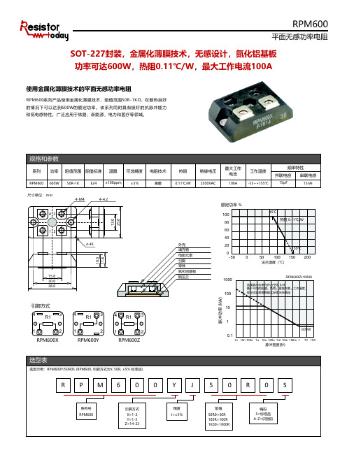
平面无感功率电阻
SOT-227封装,金属化薄膜技术,无感设计,氮化铝基板 功率可达900W,热阻0.11℃/W,最大工作电流100A
使用金属化薄膜技术的平面无感功率电阻
R P K 9 0 0系 列 产 品 使 用 金 属 化 薄 膜 技 术 , 阻 值 范 围2 5 R - 1 K Ω ,在 散 热 良 好 的 情 况 下 可 以 达 到9 0 0 W的 额 定 功 率 。 该 系 列 同 时 具 有 极 好 的 抗 脉 冲 能 力 和低电感特性。广泛应用于铁路,新能源,电力和医疗等领域。
Resistor.Today-RPM600系列SOT-227封装平面无感功率电阻规格书
4-4.2
4-4R
10.0 11.8
15.0 30.0 38.0
13.0 25.0
外壳 填充物 电阻元素 引脚 导体 氮化铝基板 铜法兰
额定功率 %
100
80
60
40
20
0
-50
0
85℃ 热阻 0.11℃/W
155℃ 50 100 150 200
法兰温度(℃)
1000 10标准品 A-Z=识别码
规格和参数
系列 功率 阻值范围 阻值标准 温飘 可选精度 电阻技术
RPM600 600W 50R-1K
E24 ±100ppm ±5%
薄膜
热阻 0.11℃/W
绝缘电压 2500VAC
最大工作 电流
100A
工作温度 -55~+155℃
频率特性
并联电容 串联电感
15pF
15nH
尺寸单位:mm 43 12
4-M4
脉冲宽度(秒)
10 100
选型表
选型示例:RPM600YJ50R0S (RPM600, 引脚方式为Y, 50R, ±5% 标准品)
R PM6 0 0 Y J 5 0 R 0 S
系列号 RPM600
引脚方式
X=1-2 Y=1-3 Z=14-23
精度 J=±5%
阻值
50R0=50R 100R=100R 1K00=1000R
连续脉冲功率允许占空比 0.01 基于不同的阻值,负载,重复次数,工作温度, 寿命试验需要根据实际情况来确定
脉冲功率 (kW)
引脚方式
4
3
R1
4
3
R1
4 R1 3
1
2
Milltronics Pointek CLS 300 电容胶带重量传感器说明书
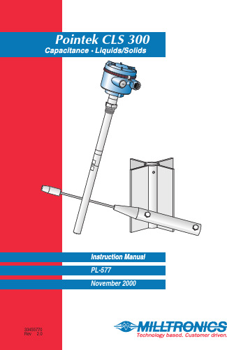
A t Milltronics,we endeavourto design equipment that is simple to use and reliable in its operation,with the aim of satisfying our customers'needs.Milltronics has been designing and manufacturing electronics based process measurement equipment since1954.Our fields of expertise include continuous and point level measurement,weighing and feeding systems and motion sensing.Technologies include ultrasonic,capacitance and microwave radar.Milltronics sells and markets world wide through subsidiaries,distributors and representatives.Through continuous improvement,we are striving to provide our customers with first rate sales information,engineering assistance and after sales support.For more details on our products and services,please contact us and we will provide you with a listing of the offices or representatives nearest you.Table of ContentsAbout Pointek CLS 300 (5)Pointek CLS 300 Outputs (5)Pointek CLS 300 Features (5)Pointek CLS 300 Applications (5)Specifications (7)Installation (11)Location (11)Configuration and Dimensions (13)Standard Version (14)High Temperature Version (15)Ceramic Active Shield Insulator (16)Thermal Isolator (16)Rod Version (16)Changing the Probe’s Length (17)Cable (19)Cable Tensile Strength (20)Cable Weights (20)Shortening the Cable (20)Mounting (21)Multiple units (21)Wall Restriction (21)Process Concerns (22)Interconnection (23)Trip Amplifier (23)Relay Output Connection (24)Solid State Switch (24)Diode Protection (24)Ancillary 2-Wire Output Connection (25)Power Connection (3 or 4 wire connection) (25)Operation (27)Set Up (27)Start Up (28)Alarm Output (29)Troubleshooting (31)Maintenance (32)Appendix I: Application Notes (33)Application Notes (33)About Pointek CLS 300Note:Pointek CLS 300 is to be used only in the manner outlined in thisinstruction manual.The Pointek CLS 300 capacitance level switch provides output on high or low process material levels. When the measured material is at the desired level, the change in capacitance is sensed and a level alarm is triggered.This could be either a “high level alarm” (material rising to reach the desired level) or a “low level alarm” (material falling to reach desired level). Pointek CLS 300 OutputsOne form `C' (SPDT) relayOne isolated, non-polarized, solid-state switchPointek CLS 300 FeaturesNPT, BSPT, JIS (other connections on request)Corrosion resistant construction, PFA, Ceramic and 316L stainless steelwetted parts25m (82 ft) maximum insertion lengthRugged shear and abrasion resistant probeFully adjustable process alarm: level, time delayField adjustable insert lengthESD protection to 55 kv continuous dischargeActive shield technologyPointek CLS 300 ApplicationsLiquids, slurries, powders, granules, and solidsChemical and petrochemicalHigh pressure and temperaturePower Industry (fly-ash)SpecificationsProbeProcess Connections:•NPT/BSPT/JIS 1Wetted Parts:•Standard Version:•AISI 316L/PFA/Peek 2•High Temperature Version:•AISI 316L/Ceramics Al203 (99.7%)2Probe Lengths:•Rod Version:•min. 350mm (14”) - max. 1000mm (40”)•Rope/Cable Version:•min. 500mm (20”) - max. 25000mm (985”) Max. Tensile Force:•1900kg (4188lbs)Pressure Range3:•-1 to +35 barg (-14.6 to +511 psig)Temperature Range3:•Standard Version:•-40 to 200 °C (-40 to 392 °F)•High Temperature Version:•-40 to 400 °C (-40 to 752 °F)•Min. Dielectric Constant (>r):• 1.5Enclosure:•AluminiumEpoxy Coated:•yesNEMA/CSA/IP-Rating:•4/Type4/IP65Cable Inlet:•2 X ½"NPTCertifications:•CENELEC/FM/CSAPower Supply and TransmitterSupply Voltage:•12 - 250 Vac/dc any polarity galvanically isolatedPower consumption:•2VA/2WattWiring connections:•max. 2.5 mm2Temperature ranges:•Operation (Storage):•-40 to 85 °C (-40 to 185 °F)Signal indicators:•3, indicating adjustment control, output status and powerAdjustment Potentiometers:•2, one for time delay adjustment, one for sensitivity adjustmentAdjustment Switches:•5PST dip switch, for time delay select, fail safe selection, time delaytest/adjust, high/low sensitivity.Min. Sensitivity:•1% change in actual capacitanceMax. Temperature Drift:•0.2% of Actual Capacitance ValueMeasurement Frequency:•600 (kHz) maxESD protection•protected to 55kV continuous discharge.Output FunctionsRelay Contact•Contact:•Form ‘C’ (SPDT)(selectable NC or NO contact)•Max. Contact Load (dc):•5A/30Vdc•Max. Contact Load (ac):•8A/250Vac (cos n=1)•Max. Switching Capacity:•150Watt/2000VA•Min. Contact Load•10mA/5Vdc•Time Delay (on and/or Off)•1 - 60 sec.Solid State switch•Output:•Galvanically isolated•Safety:•Non-polarity sensitive transistor•Max. Load:•2 Watt•Max. Switch Voltage:•250Vac/300Vdc•Max. Load Current:•100 mA•Voltage Drop•Below 1 Volt typical @ 50mA•Time Delay (On and/or Off)•1 - 60 sec.Two (2) Wire Switch•With customer supplied external trip devicesProbe - StandardLength•350mm (14”) to 1000mm (40”)Process Size•NPT, ¾” , 1”,1¼”, 1½”•BSPT, ¾”, 1”, 1½”•JIS, ¾”, 1”, 1½”Insulating Material•Standard Version:•PFA•High Temperature Version:•Ceramic•No insulation on active probeTensile kg loadProbe - CableLength • 500mm (20”) to 25000mm (985”)Process Size • NPT/BSPT: 1¼” minimumInsulating Material• AISI 316L SS • PFA insulation optionalTensile kg load• 1900 kg (4188 lbs)Electrode Dimensions • Cable (insulated):•9mm (0.35”)(uninsulated):•6mm (0.24”)• Weight:•32 x 250mm (1.26 x 9.84”)• Butterfly:•175 x168mm (6.89 x 6.61”)Approvals• CE, CSA, NRTL/C, FM, CENELEC • refer to device nameplateInstallationLocationNotes:•Installation shall only be performed by qualified personnel and in accordance with local governing regulations.•This product is susceptible to electrostatic shock. Follow proper grounding procedures.The Pointek CLS 300 as supplied in the standard probe lengths is normally mounted on the vessel top (high detection alarm) or through the tank wall at the detection level (high or low detection alarm).The cable version is designed for top mounting. The cable suspendsvertically so that it reaches into the process at the desired detection level (high or low detection alarm).Angle HorizontalVerticalConfiguration and DimensionsStandard VersionHigh Temperature VersionCeramic Active Shield InsulatorThe High Temperature version, which includes a ceramic Active Shieldinsulator, is recommended when the process temperature is greater than200E C/ 392 E F and / or when the product to be detected is very abrasive. The high temperature version is rated for applications up to 400 E C / 752 E F. See Temperature and Pressure Recommendations for Application on page 33. Thermal IsolatorIf the ambient temperature of the transmitter is expected to exceed85E C/185E F, then a thermal isolator should be used. An isolator provides a separation distance between a high process temperature inside the vessel, and the electronic housing outside the vessel. This reduces the operatingtemperature of the electronics to a value equal or less than 85E C/185E F. Rod VersionThe rod version of the CLS 300 is available in standard lengths from 350Changing the Probe’s LengthThe probe’s length can be shortened in the field by cutting the electrode.Warning:To prevent damage, do not apply torque directly to the main probe assembly.Option 11.Remove the electrode byreleasing the set screw andturning the threadedelectrode end counterclockwise2.Place the upper part of theelectrode in a vice as shownin the Figure.e a wrench to loosen thelower portion of theelectrode.Option 2The Wrong WayIf the process connection itself is put in the vice, then the probe’s internalparts will rotate along with the wrench, and the unit may fail.Cable Tensile StrengthThe tensile strength of the cable at 1900 kg / 4188 lbs should not beexceeded. It is also important to confirm that the load carrying capability of the silo/tank roof is sufficient to withstand the actual force on the cable for any conditions where the force is likely to be as great as 1900 kg / 4188 lbs.A cable (rope) probe with a PFA jacket reduces the possible product build upon the probe, thus also the tensile force on the cable.Cable WeightsA standard weight with optional attachable butterfly enhancer is available forthe cable version. For lower dielectric constant materials (often in solids) the butterfly weight is recommended, since it increases the change incapacitance when the material comes in contact with the cable end. Thiswould be the case when the silo is quite tall (> 15 m/45 ft) and the dielectric< 4)constant is less than (>rShortening the CableThe cable can be shortened using either:•An angle grinder (preferably with a disc suitable for stainless steel); or •Wire cutters (suitable for piano cable Ø6 – 9 mm).To shorten the cable, proceed as follows:1.If present, remove Butterfly from weight;2.Loosen the three set screws and remove weight by pulling it from the cable;3.Grind/cut the cable to the required length, remove rough edges from thecable;4.Insure that the cable strands are properly seated in the lay of the cable (i.e.no wire strands sticking outside the normal cable profile). It is important to insure that this step is properly done before continuing the assembly.5.Push the weight onto the cable while at the same time rotating it counter-clockwise about the cable, making sure that no cable strands are pushed out of their position in the cable and that the cable is fully inserted;6.Re-fasten the weight by tightening the three set screws;7.Attach the butterfly to the weight again.MountingMultiple unitsSensors must be 500 mm (20”)apart.Mount diagonally if there is notenough vertical space.Process Concernskeep out of path of falling material consider material angle of repose protect probe from falling materialInterconnectionTrip AmplifierLoosen the lid clip and remove the enclosure cover.Identification label (underside of enc losure cover)Notes:• Switch and potentiometer settings are for illustration purposes only.Refer to Set Up on page 27.• Relay contact terminals are for use with equipment having noaccessible live parts and wiring having insulation suitable for at least 250 V ac.• Maximum working voltage between adjacent relay contacts shall be250 V ac8A –5A –Relay Output ConnectionRelay shown in de-energized state, K2contacts rated for 8A at 250 Vac / 5A at30 VdcSolid State SwitchSolid state switch to customer’scontrol or instrumentation deviceSwitch shown in de-energized state, K3contact rated for 250 Vac / 300 Vdc 100mA max 2 VA/2W max., non-polarized.Diode ProtectionWhen driving an external relay with either the solid stated switch and / or relay outputs using dc power, protection diodes must be connected in the correct polarity across the relay coil to prevent possible switch / relaydamage due to the inductive spikes generated by the relay coil.Switch capacity100mA max.2 VA/2W max,250 Vac/300 Vdc.Ancillary 2-Wire Output ConnectionNominal 24 Vdc48 Vdc DC volts 22-2646-50R (S)120234Power Connection (3 or 4 wire connection)12 –V dcRefer to Power ConnectionOperationSet UpNote:Set up can be done in the field with the Pointek CLS 300 mounted into process, or in the shop prior to mounting.Dip Switch 1Set on to change the alarm relay status immediately when the sensor detects a change in frequency. Use this setting when time is critical.Set off to change the alarm relay status with a delay by the amount set on potentiometer #1 (P1). Use this setting when you want to slow the response to account for turbulence or false readings.Dip Switch 2Set on to change the alarm relay status immediately when the sensor detects a change in frequency. Use this setting when time is critical.Set off to change the alarm relay status with a delay by the amount set on potentiometer #1 (P1). Use this setting when you want to slow the response to account for turbulence or false readings.Dip Switch 3Set off to indicate the Low fail safe selection.Set on to indicate the High fail safe selection.Dip Switch 4Set on to test the delay of the alarm relays as set by the potentiometer #1(P1).Set off for normal operation.Dip Switch 5Set on for normal sensitivity on the sensor. Use this setting in situations when you are measuring dry solids or non-conductive liquids.S1 - 1Delay offS1 - 2Fail-safeS1 - 3Delay testS1 – 4SensitivityS1 - 5 Disabled Disabled High Test NormalEnabled Enabled Low Normal low Start UpAfter the CLS is properly mounted and the switch bank set up, apply power to the unit. The green LED (L3) lights to indicate the unit is powered andoperational.IndicatorsThe Pointek CLS uses three LEDs for visual indication of the following:L1 (yellow), sensor status:when P2 is properly set, this LED is on whenthe sensor is in contact with the processmaterial (material capacitance is greaterthan the set point, P2). L1 is off when thesensor is out of contact with the processmaterial (material capacitance is less thanthe set point).L2 (red), output status:this LED is an indication of the relay andsolid switch contact status. Refer toOperation \ Output Status.L3 (green), power:this LED is on when the Pointek CLS isproperly powered.Proceed with the set up of the alarm output.delay ‘on’delay ‘off’fail safedelay testsensitivityAlarm OutputAlarm Output StatusCoveredUn-coveredSetpoint AdjustmentIn order to assist you in properly adjusting the alarm set point for reliable and accurate detection of the process material, we have categorized the materials and applications into two cases. Follow the setup procedure associated with the case which includes your application.Case 1:This is the general case encountered in most applications, characterized by the following:• dry solids• low viscosity liquids • hygroscopic / wet solids•high viscosity and high conductivity liquidsCase 2:Case 1Preamble:•insure that L3 (green) is `on '•turn both potentiometers, P1 and P2, fully ccw (counterclockwise)•set S1 switches 1 to 4 `off ' and S1 switch 5 to `on' (normal sensitivity)1.With sensor uncovered and a minimum 100 mm free space all around, turnP2 cw until L1 (yellow) goes `on '.2.Turn P2 ccw until L1 goes `off '.Case 2Preamble:•insure that L3 (green) is `on '•turn potentiometer P1 fully ccw (counterclockwise), and P2 fully cw (clockwise)•set S1 switches 1 to 5 `off '1.Immerse the sensor in the material that has the lowest dielectric constant.L1 (yellow) should be `on '. If not, S1 switch 5 should be set to `on' (normal sensitivity).2.Adjust P2 ccw until L1 goes `off '.3.Immerse the sensor in the material that has the highest dielectric constant,L1 should come `on '.DelayThe alarm actuation can be delayed for either or both `on alarm' and `off alarm' conditions. The selection is made by setting S1-1 and S1-2, refer to Set Up \ Switch Bank. The amount of delay is adjustable from 1 to 60seconds by setting potentiometer, P1.TroubleshootingNo alarm responseL3 off (green LED)Check power supply L1 (yellow) doesn ’trespond to reducing level on the electrodeCheck sensitivity, S1-5,electrode, connections to sensor input on trip amplifier (and zener barrier continuity if used)Alarm won ’t switch when material level moves down the electrodeL1 (yellow) responds to reducing level on the electrodeCheck that relay and L2(red LED) changes state when S1-3 is toggledL1 (yellow) doesn ’t respond to the sensing electrode approaching or touching.Check sensitivity S1-5,electrode, (and zener barrier continuity, if used)L1 (yellow) responds to increasing level on the electrodeAlarm doesn ’t switch when material level moves up the electrodeL1 (yellow) flashes when approaching the alarm trip-pointCheck that relay and L2(red LED) changes state when S1-3 is toggledMaintenanceThe Pointek CLS 300 requires no regular maintenance or cleaning. Even with significant build-up on the CLS 300 level detector electrode, the level switch will continue to operate. Build-up of material on the active shield area will have little or no effect on the performance of the CLS 300.Appendix I: Application Notes Application NotesTemperature and Pressure Recommendations for ApplicationAppendix II: CE ConformityWRITTEN DECLARATION OFCONFORMITYWe,Siemens Milltronics Process Instruments B.V.Nikkelstraat 10 - 4823 AB BREDA - The Netherlands Declare, solely under own responsibility, that the product Point Level Switch,Pointek CLS 300Mentioned in this declaration, complies with the following standards and/or normative documents:Requirements Remarks Certificate No.EMC Directive 89/336/EEC Commercial, lightIndustrial, and industrial97221-KRQ/EMC 00-4024 EN 55011: 1991Emission – Class BEN 50082-2: 1995 Generic Immunity Standard, from which:•EN 61000-4-2: 1995: Electrostatic Discharge (ESD) Immunity•EN 61000-4-3: 1996: Radiated Electro-Magnetic Field Immunity•ENV 50204: 1995: Digital Radio Telephones Immunity•EN 61000-4-4: 1995: Electrostatic Fast Transient (EFT) Immunity•EN 61000-4-5: 1995: Surge Transient Immunity•EN 61000-4-6: 1996: Conducted Radio-Frequency DisturbancesImmunityATEX Directive 94/9/EC Audit Report No. 2003068II 1/ 2 GD EEx d[ia] IIC T6…T10344T 100 °C IP 66KEMA 00ATEXQ3047KEMA 00ATEX2040XEN 50014: 1992General RequirementsEN 50018: 1994 Flameproof Enclosures “d”The notified body is:N.V. KEMA – Utrechtseweg 310 – 6812 AR Arnhem – The NetherlandsLocation: Breda Named Representative: C.S. van Gils Date: October 1, 2000Position: Managing DirectorNote: For specific safety specifications, please consult the instrument labelIndex2-Wire Connection (25)3 or 4 wire connection (25)About Pointek CLS 300 (5)Adjusting Probe Length (17)Alarm Output (29)Setpoint Adjustment (29)Status (29)Ancillary 2-Wire Output Connection (25)Angle of repose (22)Appendix (33)Appendix II (34)Application Notes (33)Applications (5)Approvals (9)Cable (19)Shortening it (20)Tensile Strength (20)Weights (20)Ceramic Active Shield Insulator (16)Certifications (7)Configuration (13)DECLARATION OF CONFORMITY..34 Dimensions (13)High Temperature Version (15)Standard Version (14)Diode Protection (24)Dip Switches (27)ElectrodeShortening the Probe (17)Enclosure coverremoving (23)Falling Material (22)Features (5)High Temperature Version (15)Dimensions (15)High TemperaturesRecommendations (16)Indicators (28)Installation (11)Location (11)Interconnection (23)Ancillary 2-Wire Output Connection25Diode Protection (24)Power Connection (25)LEDs (28)Location (11)Angle (11)Horizontal (11)Vertical (11)Maintenance (32)Material build up (22)Mounting (21)Multiple Units (21)Process Concerns (22)Wall Restriction (21)Operation (27)Alarm Output (29)Set Up (27)Start Up (28)Output status (28)Outputs (5)Pointek CLS 300 (5)Applications (5)Configuration (13)Dimensions (14)Features (5)Outputs (5)Power (28)Power Connection (25)3 or 4 wire connection (25)Power Supply (7)Protection diodes (24)Relay Output Connection (24)Rod Version (16)Sensor status (28)Set Up (27)Dip Switches (27)Setpoint Adjustment (29)Shield Insulator (16)Shortening Probe (17)Solid State Switch (24)Solid stated switch (24)Specifications (7)Standard Version (14)Dimensions (14)Start Up (28)Thermal Isolator (16)Transmitter (7)CANADAGERMANYSWITZERLANDSingapore,Brazil AUSTRALIABELGIUMFRANCEHONG KONGMEXICOTHE NETHERLANDSTHE UNITED KINGDOMTHE UNITED STATES1954 Technology Dr., P .O. Box 4225,Peterborough, Ontario, Canada K9J 7B1T el.: (705) 745-2431 Fax: (705) 741-0466August van de Wielelei 97, 2100 Deurne, Antwerp, BelgiumT el.: +32(0)3326 45 54 Fax: +32(0)3326 05 25Parc de la Sainte Victoire, Bât. 5, 13590, Meyreuil, FranceT el.: +33 4 42 65 69 00 Fax: +33 4 42 58 63 95T el.: (524) 248-1561 Fax: (524) 248-1565Nikkelstraat 10, NL-4823 AB Breda, The Netherlands Tel.: +31(0)76 542 7 542 Fax: +31(0)76 542 8 542709 Stadium Drive, Arlington, Texas U.S.A. 76011T el.: (817) 277-3543 Fax: (817) 277-3894A joint venture in a sales office in and distributors in56 countries.Visit our web site at:182 Normanby Rd., Box 339, South Melbourne, AustraliaT el.: +61 3-9695-2400 Fax: +61 3-9695-2450Friedrichstrasse 69, D-76703, Kraichtal, Germany T el: +49 721 595 4607 Fax: +49 721 595 49371 Hoi Wan Street, Suite 602, Quarry Bay, Hong Kong T el.: +85 2-2856-3166 Fax: +85 2-2856-2962Century House, Bridgwater Road, Worcester, England WR4 9ZQT el: +44 1905 450500 Fax: +44 1905 450501Printed in CanadaPaseo de Loma Dorada # 114, Loma Dorada, Querétaro, Qro. 76060CP 168, Crêt de Plan 23, CH-1095 LUTRYT el. +41 21 791 58 28 Fax. +41 21 791 58 40。
宝马最全缩写,模块名称,常用缩写(已翻译中文)

A Austauschbar 可替换通过零件号码下一行AB Airbag 安全气囊ABE Allgemeine Betriebserlaubnis 普通操作许可证ABS Anti-Blockiersystem 防抱死系统AC Air Conditioning 空调器ACC Adaptive Cruise Control 自适应定速控制ACEA Association des Constructeurs Européens 结构工程师协会ACM Accessory Control Menu 备件操作面板ACSM Advanced Crash- and Safety Management 被动安全性ADB Aktive Differential Bremse 主动差速制动器ADS Adaptive Drosselklappen-Steuerung 自适应节气门控制系统AE Austauschbar/Entfallen 更换/ 取消标记AEGS Autarke Elektronische Getriebesteuerung 自给自足的电子变速箱控制系统AFS Active front steering D SteeringAGD Ansaugger?schd?mpfer 进气消音器AGM Absorbing Glas Material 铅-无纺布蓄电池AGR Abgasrückführung 废气再循环AGS Adaptive Getriebesteuerung 自适应变速箱控制系统AHK Anh?ngerkupplung 挂车挂钩AHL Adaptive Head Light 自适应转向大灯AHM Anh?nger-Modul 电子模块AHPS Advanced Head Protection System 扩展型安全气囊系统AK Ausgelagerter Kühler 清空的水箱AKF Aktiv-Kohle-Filter 活性碳过滤器AKKS Automatische Kühlklappensteuerung 冷却风门控制AKL Adaptives Kurvenlicht 自适应转向大灯AKS Anpress-Kraft-Steuerung (Wischer) 压紧力控制(刮水器) ALC Adaptive Light Control 自适应转向大灯AM Amplituden-Modulation 调制程序AMB Ambientes Licht 车内照明灯AMOeK Ausgelagerter Motor?lkühler 热量管理APM Auxiliary Power Module 辅助功率电子装置ARI Autoradio-Info-System 交通无线电ARS Aktive Rollstabilisierung 侧倾补偿ASA Aussensternangriff 螺栓技术ASC Automatische-Stabilit?ts-Control 自动稳定控制ASC+T ASC plus Traktionshilfe ASC + 牵引力辅助系统ASD Active Sound Design 音色设置AT Austauschteil 翻新件ATC Active torque control 分动器名称ATF Automatic Transmission Fluid 规格用于齿轮油AUC Automatische Umluft Control 自动车内空气循环控制AVM Automatischer Video-Multiplexer 驾驶员辅助系统AW Arbeitswert 工时单位AWE Abweichungserlaubnis 误差许可B Breite 宽度BC Bordcomputer 旅程电脑BCU Battery Change Unit DC 变压器BDC Body Domain Controller 主控制单元BEV battery powered electric vehicle 蓄电池驱动的电动车BF Beifahrer 前座乘客侧BFA Beifahrerairbag 前乘客安全气囊BFD Brake Force Display 制动力显示器BKS Bremsenkühlschacht 制动冷却通道BMS-CII BMW-Motorsteuerung C-Motor 发动机管理BMS-E BMW Motorsteuerung E-Motor 发动机管理BMS-K BMW Motorsteuerung K-Motor 发动机管理BPS BMW Premium Selection BMW Premium Selection (Marketing) BR Babyracer BobbycarBSD bit-serielle Datenschnittstelle 二氧化碳措施BT Bildtafel 图表BTE Bild-Text-Einheit 图像带零件使用信息BVA Bremsverschleiss-Anzeige 制动摩擦片磨损显示BVM Beh?lterverpackungsmenge 容器包装数量Bi-Xenon Abblend- und Fernlicht 近光和远光灯CAK Crash Aktive Kopfstütze 碰撞主动式头枕CAN Datenleitung-Bordelektronik 数据导线车载电子装置CAS Car Access System 便捷上车功能CBC Cornering Brake Control 转弯制动控制系统CBU Completely built up 部件范围本地已补充CCC Car Communication Computer Car Communication Computer CD Compact Disc 光盘CF Compact Flash 存储卡规格CFK Kohlefaserverst?rkter Kunststoff 碳纤维CHAMP Central Headunit Multimedia Plattform ??y????CIC Car Infotainment Computer Communication CenterCID Central Information Display 中央信息显示器(CID)CIM Chassis Integration Module 控制单元转向柱CIS Capacitive Interior Sensing 座位占用识别装置CKD Completely Knocked Down 完全分解的车辆CL Comfort Line Comfort LineCOP Central Ordering Process 中央订购流程CSC Cell Supervision Circuit 电池监控电子装置CSIC Carbon fiber reinforc. Silikon Carbide Carbon 陶瓷制动系统CTM Cabrio-Top-Modul 电子模块CVM Cabrio-Verdeck-Modul 控制单元CVT Continuously Variable Transmission 自动变速箱CoC Certificate of Conformity EG 合格证书D Durchmesser 直径D1 Xenon-Licht 氙气灯DAB Digital Audio Broadcasting 数字收音机DBC Dynamic Brake Control 动态制动控制DC Direct Current 直流电DC/DC Gleichspannungswandler 转换器DDC Dynamic Damping Control 半主动式底盘DDE Digitale Diesel Elektronik 数字式柴油发动机电子伺控系统DFBS Dieselfehlbetankungsschutz 防止错误的油箱加油DFK Doppel-Flachfederkontakt 插接系统DIN Deutsche Industrienorm 德国工业标准DKG Doppelkupplungsgetriebe 变速箱M3DME Digitale Motor Elektronik 数字式发动机电子伺控系统DOT Department of Transportation 美国交通部DPC Dynamik Performance Control 驱动扭矩分配DPF Dieselpartikelfilter 炭烟微粒过滤器DS Dichtungssatz 密封组件DSC Dynamische Stabilit?ts Control 动态稳定控制DSP Digital Sound Processing 数码音响处理器DTC Dynamische Traktions Control 防滑调节装置DVD Digital Versatile Disc 数字化多功能光盘DVG Deutsche Vergaser Gesellschaft 制造商DWA Diebstahlwarnanlage 防盗报警系统DXC Dynamic X Control 四轮驱动汽车上的动态行驶调节E Entfallen 取消(不再提供)E-Masch. E-Maschine 电动机EAS Electronic Active Steering ???????EBA Einbauanleitung 安装说明EC Elektrochrom 电致变光技术ECE Economic Commission for Europe 特殊的目录版本EDC Electronic Damper Control 电子减震控制装置EDH Elektrischer Durchlauferhitzer 加热器EG-BE Europ. Gesamt-Betriebserlaubnis EU 使用许可证EH Elektro-Hydraulisch 电动液压控制EKK Elektrischer Klimakompressor 压缩机EKMV Elektr. K?ltemittelverdichter 空气调节装置EKP Elektrische Kraftstoffpumpe 燃油泵ELA Einzelleiter Abdichtung 防潮插头ELV Elektrische Lenks?ulenverriegelung 电动转向柱锁EMA-AE Elektr, Motorantrieb-Antriebseinheit 电动驱动单元EMCD Electro-Magnetic Control Device 悬挂离合器EME Elektromaschinen-Elektronik 电动马达混合动力车辆EMF Elektromechanische Feststellbremse 电动机械式驻车制动器EML Elektronische Motorleistungs Regelung 发动机功率电子控制系统EMV Elektromagnetische Vertr?glichkeit 抗干扰滤波器EPB Elektrische Parkbremse 电动驻车制动器EPROM Erasable Programmable Read Only Memory 存储芯片(控制单元) EPS Electronic Power Steering 电动支持的转向系ESA Electronic Suspension Adjustment 电子减震器调节ESD Electrostatic Discharge 静电放电ESG Einscheibensicherheitsglas 安全玻璃ESL Einschichtlackierung 油漆ETC Electronic Toll Collection 高速公路费用记录ETK Elektronischer Teilekatalog 计算机管理零件目录EU2 Europ?ische Abgasnorm 2 欧洲废气排放标准2EU3 Europ?ische Abgasnorm 3 欧洲废气排放标准3EU4 Europ?ische Abgasnorm 4 欧洲废气排放标准4EU5 Europ?ische Abgasnorm 5 欧洲废气排放标准5EU6 Europ?ische Abgasnorm 6 欧洲废气排放标准6EVO Evolution 进一步发展EWB Extended Wheel Base 加长型EWP Elektrische Wasserpumpe 电动水泵EWS Elektronische Wegfahrsperre 电子防驶离装置FAKRA Normenausschuss Kraftfahrzeuge 车辆专业技术标准委员会FBAS Farbbild-Austast Sychronsignal 彩色画面信号FBD Fernbedienung 遥控器FBM Functional Bookmarks 可设置的功能按钮FCD Floating Car Data 实时交通引导系统FCKW Fluorchlorkohlenwasserstoff -->R12 氯氟烃FDC Fahrdynamik Control 驱动系统FEM Front Electronic Module 控制单元FG Funktionsgruppe 功能组FG -> Ab Fahrgestellnummer 底盘号码FGS Fussg?ngerschutz 行人碰撞保护装置FH Fensterheber 车窗升降机FLA Fernlichtassistent 驾驶员辅助系统FM Frequenz-Modulation 调制程序FPM Fluorpolymer-Kautschuk 弹性体FRM Fussraum Modul 车身功能控制单元FRU Flat Rate Unit 工时单位FSC Freischaltcode 启用代码FU Frisch-/Umluft 出风口FZD Funktionszentrum Dach 车身控制单元Funk Funkfernbedienung 后视镜功能GAL utst?rkeregelung 根据车速音量自动调节GHAS Geregelte Hinterachssperre 差速锁GM Grundmodul 基本模块(GM)GOeK Getriebe?lkühler 变速箱油冷却器GPS Global Positioning System 导航系统GSM Global System for Mobile Communication 通信系统GTO Gate Turn Off 车库开门器GWS Gangwahlschaltung 自动H2 Wasserstoff 氢气HA Hinterachse 后桥HAG Hinterachsgetriebe 后驱动桥HC Heading Control 辅助系统HD Heavy Duty 恶劣的工作条件HDC Hill-Descent-Control 下坡行驶辅助HDP Hochdruckpumpe 直接喷射系统HF Hochfrequenz 高频HFM Heissfilm-Luftmassenmesser 空气质量计HG Hauptgruppe 总成分组HOD Handsoffdetection 控制单元HP High Performance High PerformanceHPS Head Protection Sytem 安全气囊系统HS Handschaltung Hand switchHSD High Speed Data 快速数据传输HSG H?r-Sprech-Ger?t 对话装置HSR Hinterachs-Schr?glaufregelung 底盘HSS H?henstandssensor 用于大灯光线水平调整HU-B Headunit basic 继任型号CICHU-H Headunit high 继任型号CICHUD Head-Up Display 位于头上方的显示器HV High Voltage 高压系统HVS Hochvoltspeicher 高压储能器HWS Hinweisschild SchildI übersetzungsverh?ltnis 齿轮齿数比I-ABS Integral ABS 防抱死系统IBOC In Band On Channel 数字收音机美规IBS Intelligenter Batteriesensor 蓄电池管理系统ICAM Integrierte Kamera 摄像系统ICM Integrated Chassis Management 控制单元ICOM Integrated Comminication Optical Module Integrated Comminication Optical ModuleICS Indoor communication system Indoor communication system (Marketing) IHKA Integrierte Heiz-Klima-Automatik 集成的冷暖自动空调IHKAF Integrierte Heiz-Klima-Automatik + MF 集成的冷暖自动空调+ MF IHKR Integrierte Heiz-Klima-Regelung 集成的冷暖空调器调节IHKRF Integrierte Heiz-Klima-Automatik + MF 集成的冷暖自动空调+ MFIHR Integrierte Heizungs-Regelung 集成式暖风器控制IHRF Integrierte Heizungs-Regelung plus MF 集成式暖风器控制正极MFIKT Informations-/Kommunikationstechnologie Information/communications technologyIMIB Integrated Measurement Interface Box 测量系统ISPAIMS Instant Mobility System 瞬时机动性系统ISA Innensternangriff 螺栓技术ISIS Integrated Service Information Server EPC 和保养数据硬件基础ISO Isolationsüberwachung 绝缘监控ISPA Integrated Service Processes Application 修理厂计划系统ITS Inflatable Tubular Structure 头部安全气囊IWT Innerer W?rmetauscher 热量管理Indi. Individual 个性化JCW John Cooper Works JCWJPT Junior Power Timer 插头接点系统KA Klimaanlage 空调器KAFAS Kamerabasierende Fahrerassistenzsysteme 驾驶员辅助系统KAT Katalysator 废气触媒转换器KB Kraftbegrenzer 安全带系统KBA Kraftfahrt-Bundesamt 联邦车辆局KBB Kabelbaum 电线束KG Kurbelgeh?use 曲轴箱KKB Komplettkabelbaum 整套导线束KLE Komfort Lade Elektronik 控制单元KM Kühlmittel 冷却液KSK Kundenspezifischer Kabelbaum 客户专用电线束KW Kilowatt 千瓦KaFAS Kamerabasierende Fahrerassistenzsysteme 辅助系统Kompass Digitale Kompassanzeige 后视镜功能L L?nge 长度LAZ Lagerzeit 存放时间LBV Lehnenbreitenverstellung 靠背宽度调整动态LCI Life Cycle Impulse 改型LCPA LIN-Controlled Power Amplifier 功率放大器LDM L?ngsdynamik-Management 四轮驱动汽车上的动态行驶调节LED Light Emitting Diode 发光二极管LH Left Hand Left sideLHD Left-Hand-Drive 左座驾驶型LHT Left Hand Traffic 左侧行驶LIM Lade-Interface-Modul 充电模块LIN Local Interconnection Network 控制单元联网LMR Leichtmetallrad 轻质合金轮辋LOM Licht-Optik-Modul 蓄电池监控LRR Long Range Radar 雷达系统LSC Leichtbauweise-Stahl-Compact 轻型结构LSK Laststrom-Kontakt 插接系统LTE Long Term Evolution 移动无线电标准LVDS Low Voltage Differential Signal 快速数据传输LVM Lagerverpackungsmenge 仓库包装数量LWL Lichtwellenleiter 光缆LWR Leuchtweitenregulierung 大灯光线水平调整M Manuelles Getriebe 手动变速箱MAK Modular Automobil Kontakt 插接系统MAM Mindestabnahmemenge 最小定购量MASK Multimedia Audio System Kontroller 多媒体音频系统控制器MCON Multicontakt 插接系统MCP Multi Contact Point 插接系统MDK Miniatur Doppelflachfeder Kontakt 插头接点系统MF Mikrofilter 微尘滤清器MFL Multifunktionslenkrad 多功能方向盘MFS Multifunktions-Sitz 内饰MFT Multifunktionstr?ger 架梁MID Multi Information Display 多功能信息显示器MLK Mini Lamellen Kontakt 触点插接系统MMC Multimediachanger DVD 转换匣MOST Media Oriented System Transport 总线系统MOeK Motor?lkühler 发动机油冷却器MPQ Micro-Power-Quadlock 插接系统MPV Multiple Purpose Vehicle 多功能轿车MQS Micro-Quadlock-System 插接系统MSA Motor-Start/Stop-Automatik 二氧化碳措施MTB Mountainbike 山地车MTF Multi-Transmission-Fluid Langzeit-Getriebe?lMULF de-/Freisprecheinrichtung 充电设备/ 免提通话设备Mü Modellüberarbeitung 改型NAFTA North Atlantic Free Trade Agreement 自由贸易区美国、加拿大和墨西哥NAS North American Standard 美国解决方案AHKNBG Next Bike Generation 新一代车架NBK Nytril-Butadien-Kautschuk 弹性体NFC Near Field Communication 无线通信技术NOX Stickoxid 废气NSD Nachschalld?mpfer 后消音器NSL Nebelschlussleuchte 车辆照明系统NSW Nebelscheinwerfer 车辆照明系统NVC Night Vision Camera 夜视照相机NoS No Stock 部件未集中安置OBD On-Board-Diagnose 诊断系统OC3 Occupancy mat 座椅座垫OCS Outdoor communication system Outdoor communication system (Marketing)OGW Onboard-Diagnostic-Gateway 诊断接口PAV/PAX Pneu Acrosach Vertical 轮胎防爆胎辅圈PCA Passive Car Access 便捷上车功能PCM Phase change materials FunktionsmaterialPD Paris-Dakar 汽车拉力赛PDC Park Distance Control 泊车辅助系统PDM Power Distribution Module 供电PEB Power Electonic Box 功率电子装置PEU Power Electronics Unit 总成分电器及主电线束PGS Passive Go Steuerger?t 驾驶员识别系统PI Produktinformation 产品信息PK Power Kit 动力工具包PLATO Planungstool 备件计划工具PLCD PermanentmagnetLinearContactlessDisplace 传感器怠速识别PM Partikelmass 质量相关的颗粒极限值PMA Parkman?ver-Assistent 驾驶员辅助系统POI Points of Interest 兴趣点PPS Paint Preparation System 一次性混合烧杯油漆PT-Schr. Markenname 攻螺纹螺栓用于塑料PTC Positive Temperature Coefficient 热敏电阻PTO Power take off 分动器名称PTS Pressure Tube Sensor 压力软管传感器PTT push to talk 语音输入QL Quer- und L?ngsdynamik 动态行驶调节QMV Quermomentverteiler 后驱动桥R Rechtslenker 右座驾驶型R12 FCKW-haltiges K?ltemittel 含氟氯化碳的制冷剂R134A FCKW-freies K?ltemittel 不含氟氯化碳的制冷剂RAL Reichsauschuss für Lieferbedingungen 颜色标准RDC Reifen-Druck-Control 轮胎压力监控RDME Range Extender DME 发动机电子系统REXRDS Raddrehzahlsensor 车轮转速传感器REM Remote Equipment Module 控制单元REMA Reversibler Elektromotorischer Aufroller 自动收卷器REME Range Extender E-Motor Elektronik 电动马达电子装置REP Reparatursatz 修理套件REX Range Extender 增程装置RFK Rückfahrkamera 倒车摄像机RFT Run Flat Technologie 轮胎带紧急运行系统RH Right Hand Right sideRHD Right-Hand-Drive 右座驾驶型RHT Retractable Hardtop 硬车顶(可收放式)RKLE Rundumkennleuchte 旋转式标志灯RLS Regen-/Lichtsensor 照明ROC Roll Over Control 翻车保护ROZ Research-Oktanzahl 燃油等级RPA Reifen-Pannen-Anzeige 轮胎失压显示RPS Rapaid Preparation System 一次性混合烧杯油漆RS Regensensor RegensensorRSC Runflat System Component 轮胎带紧急运行系统RSE Rear Seat Entertainment 加装套件后座区视听设备RSI Rear Seat Infotainment 加装套件后座区视听设备RTTI Real-Time Traffic Information 远程信息处理系统RTTM Real-Time Tracking Modul 远程信息处理系统RWS Richtwinkelsatz 车身矫直系统RZV Ruhende Zündspannungsverteilung 单独的点火线圈RoW Rest of World 如非ECESA Sonderausstattung 特殊装备SAF Synthetic Axle Fluid 后驱动桥用油SAF. Semiaktives Fahrwerk 动态行驶调节SAP SIM Access Profile 传输协议蓝牙SAS SA-Steuerger?t 集成控制单元SAV Sports Activity Vehicle Sports Activity VehicleSAW Shielded access to Wireless LAN Shielded Access to Wireless LAN SAZ Sonderausstattung Zubeh?r 接近批量生产的备件SBA Sensotronic Brake Actuation 用于混合动力车的制动系统SBK Sicherheitsbatterieklemme 蓄电池接线柱SBT Service-Information BMW Technik 维修信息技术SCA Soft-Close-Automatik 自动软关闭装置SCR Selective Catalytic Reduction 废气净化氮氧化物SDARS Satellite Digital Audio Radio Service 卫星接收SDB Sicherheitsdatenblatt 安全数据单SG Steuerger?t 控制单元SGS Sitzintegriertes Gurtsystem 座椅集成式安全带系统SI Service-Information 服务信息SIP Schulungs- und Informationsprogramm 培训自学程序SKR Sommerkomplettrad 夏季完整车轮SLE Speicher Lade Elektronik 控制单元混合动力车辆SLI Speed Limit Info 驾驶员辅助系统SLK Sensor Lamellen Kontakt 触点插接系统SLP Stromlaufplan 电路图SLS Sekund?rluftsystem 二次空气系统SMB Subminiatur Version B 插接系统天线导线SME Speicher Management Elektronik 控制单元蓄能器管理SMG Sequenzielles Manuelles Getriebe 自动换档控制的手动变速箱SML Seitenmarkierungsleuchte 示宽灯SOP Start of Produktion 批量使用开始SPEG Smart Power Electronics Gateway 车身功能控制单元SPnM Sitz Pneumatik Modul 控制单元座椅舒适功能SRA Scheinwerferreinigungsanlage 大灯清洗装置SRD Supply and Replenishment Dealership 部件补给系统SRP Service-Reparatur-Pakete 售后服务维修附件包SRR Short Range Radar 雷达系统SRS Safety Restraint System / Airbag 安全制动系统/ 安全气囊SRT Sun Reflective Technology 红外线反射皮革SSG Sonnenschutzglas 茶色玻璃SSR Sonnenschutzrollo 遮阳卷帘SST Start Stop Taste 车辆起动STV Sitztiefenverstellung 座椅深度调整SW Schlüsselweite 扳手开口度SZ Sonderzubeh?r 特殊附件SZL Schaltzentrum Lenks?ule 开关中心转向柱SZT Schaltzentrum Türe 控制单元Stg. Steuerger?t 控制单元TCB Telematics Communication Box 控制单元电话TCU Telematics Control Unit 电子信息系统控制单元TFL Tagfahrleuchten 车辆照明系统TI Technische Information 技术信息TIS Technisches Informations System 技术信息系统TLC Time to Line Crossing 驾驶员辅助系统TLEV Transitional Low Emission Vehicle 许可等级低废气值TLL Teilelebenslauf 零件寿命周期TMC Traffic Message Channel 交通无线电TPA Telematik Plattform. Accessory 远程信息处理平台附件TRSV Top Rear Side View 控制单元TTS Target tracking system Ziele-VerfolgungssystemTüV Technischer überwachungs Verein 制造商证明UBS Unterbodenschutz 底部保护层UCX Unit Charging Extension 控制单元充电ACDCUERSS überrollschutz 翻车保护UG Untergruppe 分总成ULF Universelle Lade- u. Freisprecheinricht. 通用充电和免提通话设备UPE Unverbindliche Preisempfehlung 不具有约束效力的建议价格USB Universal Serial Bus 通用PC 接口USIS Ultraschall Innenraumschutz 车内防盗监控传感器VA Vorderachse 前桥VDC Vertical Dynamic Control 行走机构技术VDP Vertikaldynamikplattform 四轮驱动汽车上的动态行驶调节VF Verkehrsfunk 交通无线电VGSG VerteilerGetriebeSteuerGer?t 控制单元VHT Versenkbares Hardtop 硬车顶(可收放式)VICS Vehicle Information&Communication System 车辆信息系统VIN Vehicle Identification Number 底盘号码VMS Vehicle Management System 控制单元BEVVOC Volatile Organic Compounds 挥发性有机溶剂VSG Vehicle Sound Generator 发动机噪声模拟VVM Vorverpackungsmenge 预包装数量VVT Variabler Ventiltrieb 可调式阀门控制WAPU Wasserpumpe 水泵WBA Warnblinkanlage 闪烁报警装置WEBA Werkstatt-Einbauanleitung 关于ASAP 的安装说明WKR Winterkomplettrad 整套冬用轮胎WP Winterpaket 特殊装备S4T9AWSA Wechselsprechanlage 双向通话装置ZBE Zentrales Bedienelement iDrive ControllerZE Beidseitig austauschbar/Entfallen 更换/ 取消标记ZFE Zentrale Fahrzeug-Elektronik 控制单元ZGM Zentrales Gateway Modul 网关模块ZKE Zentrale Karrosserie-Elektronik 车身功能控制单元ZKW Zizala Karl Wien 供货商照明系统ZSG Zweischeibensicherheitsglas 安全玻璃ZV Zentralverriegelung 中控锁ZWSL Zweischichtlackierung 油漆gHAS geregelte Hinterachssperre 差速锁。
Resistor.Today-RNP50S系列TO-247封装平面无感功率电阻规格书
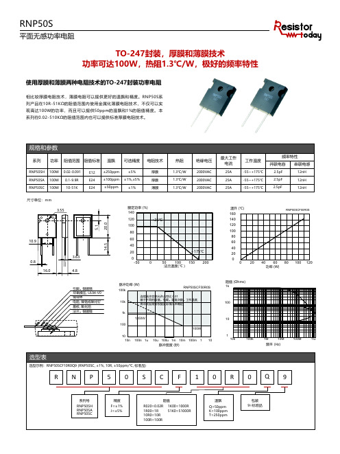
引脚,铜镀锡 环氧模压, UL94-V0 铜导体 电阻, 镍铬或氧化钌 基板, 氧化铝 法兰,铜镀镍
脉冲功率 (W) 100k
RNP50SCF50R0S
连续脉冲功率允许占空比 0.0,
寿命试验需要根据实际情况来确定
1k 1350W
100 100W
10 10n 100n 1u 10u 100u 1m 10m 100m 1 10 脉冲宽度 (秒)
阻值
R020=0.02R 1R00=1R 10R0=10R 100R=100R
1K00=1000R 51K0=51000R
温飘
Q=50ppm K=100ppm T=250ppm
包装 9=标准品
RNP50S
平面无感功率电阻
TO-247封装,厚膜和薄膜技术 功率可达100W,热阻1.3℃/W,极好的频率特性
使用厚膜和薄膜两种电阻技术的TO-247封装功率电阻
相 比 较 厚 膜 电 阻 技 术 , 薄 膜 电 阻 可 以 提 供 更 好 的 温 飘 和 精 度 。R N P 5 0 S系 列 产 品 在1 0 R - 5 1 K Ω的 阻 值 范 围 内 使 用 金 属 化 薄 膜 电 阻 技 术 , 不 仅 可 以 实 现 高 达1 0 0 W的 功 率 , 而 且 可 以 提 供5 0 p p m的 温 飘 和1 %的 阻 值 精 度 。 本 系列在0.02-510KΩ的阻值范围内也可以提供标准厚膜电阻技术。
阻值 (Ohms) 1k
100
10
1 10k
100k
1M
10M
100M
1G
频率 (Hz)
选型表
选型示例:RNP50SCF10R0Q9 (RNP50SC, ±1%, 10R, ±50ppm/℃, 标准品)
- 1、下载文档前请自行甄别文档内容的完整性,平台不提供额外的编辑、内容补充、找答案等附加服务。
- 2、"仅部分预览"的文档,不可在线预览部分如存在完整性等问题,可反馈申请退款(可完整预览的文档不适用该条件!)。
- 3、如文档侵犯您的权益,请联系客服反馈,我们会尽快为您处理(人工客服工作时间:9:00-18:30)。
4-M4
4-4.2
4-4R
10.0 11.8
15.0 30.0 38.0
13.0 25.0
外壳 填充物 电阻元素 引脚 导体 氧化铝基板 铜法兰
引脚方式
4
3
R1
4
3
R1
4 R1 3
1
2
RPM300X
1
2
RPM300Y
1
2
RPM300Z
脉冲功率 (kW)
额定功率 %
100 80 60 40 20 0 -50 0
选型表
选型示例:RPM300YJ10R0S (RPM300, 引脚方式为Y, 10R, ±5%)
R PM3 0 0 Y J 1 0 R 0 S
系列号 RPM300
引脚方式
X=1-2 Y=1-3 Z=14-23
精度 F=±1% J=±5%
阻值
R100=0.1R 1K00=1000R 1R00=1R 10K0=10000 10R0=10R 100K=100000R 100R=100R 1M00=1000000R
RPM300
平面无感功率电阻
SOT-227封装,厚膜技术,氧化铝基板 功率可达300W,热阻0.23℃/W,最大工作电流100A
使用厚膜电阻技术的SOT-227封装功率电阻
R P M 3 0 0系 列 产 品 使 用 金 属 化 厚 膜 电 阻 技 术 , 在 散 热 良 好 的 情 况 下 额 定 功 率 高 达3 0 0 W, 阻 值 范 围 是0 . 1 - 1 M Ω, 温 飘 为 ±1 0 0 p p m, 精 度 为 ±1 %, ±5 %。 提 供 多 种 引 脚 方 式 , 满 足 客 户 不 同 需 求 。 该 系 列 同 时 具 有 极 好 的 抗 脉冲能力和低电感特性。广泛应用于铁路,新能源,电力和医疗等领域。
编码 S=标准品 A-Z=识别码
85℃ 热阻 0.23℃/W
125℃
155℃ 50 100 150 200
法兰温度(℃)
1000 100
RPM300ZJ10R0S
连续脉冲功率允许占空比 0.01 基于不同的阻值,负载,重复次数,工作温度, 寿命试验需要根据实际情况来确定
10
1
300W 0.1
1n 10n 100n 1u 10u 100u 1m 10m 100m 1 10 100 脉冲宽度(秒)
规格和参数
系列 功率 阻值范围 阻值标准 温飘 可选精度 电阻技术
RPM300 300W 0.1-1M
E12 ±100ppm ±1%
绝缘电压 2000VAC
最大工作 电流
100A
工作温度 -55~+155℃
频率特性
并联电容 串联电感
15pF
15nH
尺寸单位:mm 43 12