CAS CI-1280使用说明书
雷卡生物系统氨氨酸酶活性试验试剂盒说明书

Leica IP C
3
目录
1. 重要信息 ............................................................................................................................................... 6
4. 仪器安装 .............................................................................................................................................26
以印刷、影印、缩影、网络摄像或其他方法 — 包括任何电子系统和媒介 — 复制本文档的 文本和插图 (或其任何部分) 需要事先征得 Leica Biosystems Nussloch GmbH 的明确书面许可。
欲知仪器序列号和制造年份,请参阅仪器背面的铭牌。
Leica Biosystems Nussloch GmbH Heidelberger Str. 17 - 19 69226 Nussloch Germany 电话: +49 - (0) 6224 - 143 0 传真: +49 - (0) 6224 - 143 268 网站:
4.1 安装地要求..........................................................................................................................................................................26 4.2 仪器拆箱 ...............................................................................................................................................................................26 4.2.1 安装打印机..........................................................................................................................................................................28 4.3 标准配置 ...............................................................................................................................................................................29 4.4 安装手动卸载站点...........................................................................................................................................................30 4.5 自动卸载站点 (选配) .......................................................................................................................................................31 4.6 安装/更换闪光灯泡 .........................................................................................................................................................32 4.7 填充和插入储存条...........................................................................................................................................................35 4.8 电气连接 ...............................................................................................................................................................................40 4.9 将运输墨盒更换为油墨墨盒 ......................................................................................................................................41 4.10 安装打印机驱动程序......................................................................................................................................................48
斯卡西亚说明书
斯卡西亚实验仪器说明书斯卡西亚说明书一、仪器概述斯卡西亚是一款高效便捷的实验仪器,主要用于科研、教学和工业生产等领域。
它具有高精度、易操作和多功能等特点,能够满足各种实验需求。
二、硬件规格1.电源:110-240V,50-60Hz,消耗功率<50W。
2.主机尺寸:420mm x 340mm x 160mm。
3.重量:约7.5kg。
4.显示器:4.3英寸彩色触摸屏。
5.键盘:带有电源开关、菜单键、四个方向键和12个功能键。
三、功能特点1.高精度测量:采用先进的激光干涉仪技术,可以实现高精度的长度、角度和直线度测量。
2.多功能测量:具备长度、角度、直线度、表面粗糙度等多种测量功能,适用于不同实验需求。
3.数据分析:内置数据处理功能,可以对测量数据进行统计、计算、拟合和导出等操作。
4.操作便捷:采用人性化的操作界面和便捷的键盘设计,使得操作更加简单易懂。
5.高可靠性:采用高品质的电子元件和结构设计,确保仪器在长时间使用中具有高稳定性和可靠性。
四、使用步骤1.打开电源开关,仪器自检后进入测量界面。
2.选择合适的测量功能,根据提示进行测量。
3.将被测物体放置在测量台上,调整测量位置和角度。
4.按下测量键,仪器会自动完成测量,并在显示器上显示测量结果。
5.根据需要使用其他功能键进行数据处理和导出。
6.关闭电源开关,清洁仪器表面。
五、维护保养1.保持仪器表面清洁,避免长时间接触液体或其他腐蚀性物质。
2.定期检查电缆和连接器,确保电气部分安全可靠。
3.定期进行精度校准,以保证测量结果的准确性。
4.不使用时,应将仪器放置在干燥、通风的地方,避免阳光直射。
六、常见问题及解决方案1.仪器无法开机:请检查电源连接是否正常,如有问题请联系专业人员。
2.测量结果不准确:请检查测量台是否水平,测量距离是否正确,如有需要请进行精度校准。
3.显示器无响应:请检查电缆连接是否牢固,如有问题请联系专业人员。
4.功能键无法使用:请检查功能键设置是否正确,如有问题请参考用户手册或联系专业人员。
水抗挥发性盐度测试笔规格及操作说明书
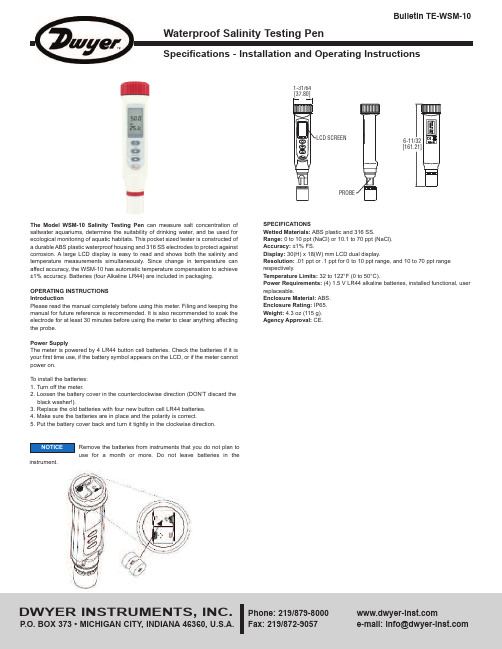
Specifications - Installation and Operating InstructionsBulletin TE-WSM-10- C or F is the unit of the liquid temperature.- is the battery low icon.KeypadOperation1. Remove the probe cover from the meter to expose the electrode.2. Press to power on the meter. The LCD will display parameters (ex: tnr, tCo, tds,rAn) in turns and then it will enter normal display.accuracy. Alternatively, you can manually select the ranges. For example, if you prefer the meter to display a reading such as .50 mS instead of 500 uS, you press for more than 2 seconds.measurement mode. When the reading is stable, the unit will stop flashing.10. Press to freeze current readings. The text “Hold” will appear on the LCD. Pressagain to release.11. Turn off the meter by pressing .12. Make sure your electrode is clean and store it carefully. Before storage, rinse itcarefully in de-ionized water and store dry with the cap. Remember the storage temperature limits. For more information, see the maintenance section.13. Air bubbles can easily adhere around the gap between the electrode and theTo disable the auto power off:Before power on, press + simultaneously until an “n” appears on the screen. Then, release the keys to return to normal mode.The advanced setup mode lets you customize your meter’s preferences and defaults. To change the parameters, you can press for more than 2 seconds. You will enter setup mode when the meter is in measurement mode.1. When the meter is in measurement mode, press f for more than 2 seconds toenter setup mode.2. Press , , or to select P1.0.3. Press momentarily again to enter unit setting.4. Press or to select C or F.5. Press momentarily to confirm the unit, or press it for more than 2 seconds toreturn to P1.0 without saving.6. While in P1.0, press for more than 2 seconds to return to measurement mode. P3.0 Reset Meter (rSt)When you decide to reset the meter, all parameters will be reset to factory default values, including the calibration information.1. In P3.0, press momentarily to enter P3.1.2. Press or to select Y or N.3. Press momentarily to confirm the state and return to P3.0, or press it for morethan 2 seconds to return to P3.0 without confirming the P3.1 value.P4.0 Review Calibration Information (CAL)In P3.0, press or to select P4.0.P4.1 Range 1 Calibration Informationpress momentarilyconcentration. If the meter is not yet calibrated, “---”will display on the LCD.In P4.1 or P4.2, press momentarily to confirm the state and return to P4.0. In P1.0, P2.0, P3.0, P4.0, you can press for more than 2 seconds to return to1. Turn off the meter and stay in normal measurement mode.2. Press or for more than 2 seconds to select the range.(Default)temperature.7. Press for more than 2 seconds to begin the calibration. The SALT value willblink on the LCD.8. Press the or to adjust the value to match the value to the calibrationstandard. You can adjust the SALT reading up to ±30% from the detected value.9. When the “CAL” stops blinking, you can press to confirm the value. The meterwill switch back to SALT measurement mode. If “CAL” always blinks, check theThe text P1.1, P1.2, P1.3, P2.1, P3.1 will not displayLCD.NOTICE。
莱茜汽缸有限公司产品说明书

OriginalInstallation and service instructionKnife gate valvesTable of contentsA)General (2)A1Symbols (2)A2Valve destination (2)A3Related documents (2)A4Valve marking (3)A5 Transport, storage and handling (3)Storage and transport: (3)Handling: (3)B)Installation/functional check (4)B1Safety warnings at installation (4)B2Conditions for installation (4)B3Pressure, flow direction and valve position (5)B4Necessary support for special cases (5)B5Steps to install (5)B6Installation in an ATEX-classified area (7)B7Pressure testing after installation (if necessary) (8)B8Disassembling the valve (8)C) Service and maintenance (9)C1Safety warnings at service and maintenance (9)C2Manual and automatic actuation (10)C3Maintenance (10)C4Troubleshooting (10)Declaration in compliance with EU-Directives (11)All specifications are subject to change without notice.Knife gate valvesA) GeneralIn this instruction a “knife gate valve” is shortly called “valve”.A1 SymbolsXXXXXwarranty of the manufacturer.A2 Valve destinationValve types BV, D2G, HG, HL, HP, JTV, MP, MV, RKO, RKS, SLF, SLV, SLH, SLX, TV, XV and WB are destined – after installation between flange(s) in a pipe system – to shut off, to open or to control the flow within the admissible pressure/temperature limits.These pressure and temperature limits depend on the materials of valve body, gate and seat. Temperature limits are defined in the valve data sheet of each type. Maximum working pressure are marked at the valve body and on the label attached on the beam.The flow shall be without vibrations and/or pressure chocks. The surrounding environment should not imply any risk to the valve. This also implies to explosive environment – except for valves classified for ATEX- area and marked accordingly.Installation of the knife gate valve is preferred with the actuator in an upward position – except for RKO, JTV and D2G. At valve operation respect:∙The manufacturers declaration to EC directives,∙This original installation and service instruction which is supplied together with the valve.Stafsjö Valves AB does not accept any responsibility if this “Valve destination” is not observed.A3 Related documentsFurther information on the valves is available on .ds+valve type (i.e. ds-BV) = Data sheet with technical information (dimensions, material specification etc.)mi+valve type (i.e. mi-BV) = Instructions for maintenance on each valve type.sp+valve type (i.e. sp-BV)=Specify spare parts for each valve type.acc+type of accessory (i.e. acc-SV)= Accessory for different types of valves. I.e solenoid valve.stafsjo-valve-spec = Specification of parts and valve combinations.Knife gate valvesA4Valve markingThese labels shall not be removed, over coated or otherwise covered.Refer to the “Serial Number” of the valve marking at any contact with Stafsjö.A5 Transport, storage and handlingNoteAdditional requirements may be found in the actuator instruction, if any.Storage and transport:Keep the valve in open position during storage to ensure its function and to protect the polished surface of the gate. Store the valve in a clean and dry environment and protect it against dirt, dust and other contamination. Do not expose the valve to direct sunlight. If the valve is stored outside, it shall be wrapped tightly in a plastic foil or similar to protect it against moisture or any dirt contamination. It should also be stored high enough without any risk to be covered in snow or enclosed by water.Handling:Lifting and moving shall be carried out with soft straps. Place and fasten the soft strap on the valve body as shown in fig.1. Make shure that all equipment is designed to hold the weight of the valve.Never place lifting equipment:• On the actuator, accessories or gate guards.• In the bore of the knife gate valve, since it cause damages to the seat and retainer ring.Label for identification of seat and gate materialFig.1Ser.No: Serial number consisting of year – individual no - order number.CE-marking when applicable.Max PS Valvebody/differential: 10/10 BARKnife gate valvesSpecifically note that threaded hole on top of pneumatic cylinder type EC, is onlyfor handling the cylinder itself. See figure 2.B) Installation/functional checkThis instruction includes safety recommendations for foreseeable risks at installation into a (pipe) system. The user is responsible to complete this instruction with warning notes for system-specific aspects. All requirements of the system shall be observed.B1Safety warnings at installation∙∙∙∙∙Danger1.2.to prevent people getting to close to the valve and being exposed to the media transported in the system when the valve opens.People’s life and health is at stake if this is not observed. Any other action is the responsibility of the user.B2Conditions for installationMake sure:∙ To install valves according “Valve destination”, see section A2. Observe valve marking, see section A4.∙ That the pipe section is not exposed to vibrations or other mechanical stresses which could deform the valve body and affect the valve‟s tightness and/or ability to operate.∙ That the valve environment does not imply any risk to the valve, the actuator or the accessories. This also implies to explosive environment – except for valves classified for ATEX- area and marked accordingly. ∙ That flanges, pipe line and the valve are empty, free from solid and sharp particles.∙ That the valve is installed between flange(s) (fixed or loose) to ensure that the valve is securely fixed and that the flange keeps tight.∙ That the knife gate valve is protected against radiant heat, if the valve is placed near a heat source whose temperature exceed maximum allowable temperature for the valve or its actuator.∙ The mating (=gasket contact) surface of the flange cover the retainer ring completely. Detailed information on flange drilling, threads, length and number of bolts is available in data sheet on . ∙ To follow those instructions which are supplied with an actuator (if any). ∙ The pipe line is free from pressure.∙ Additional requirements may be found in the actuator instruction – specifically to adjust the correct OPEN andCLOSED positions before the valve is installed.OKFig.2Knife gate valvesB3 Pressure, flow direction and valve positionWhen the knife gate valve is open, P1=P2, the pipe line pressure may notexceed maximum allowable working pressure body according to each valve.When the valve is closed, the differential pressure ∆P, is the difference between P1 and P2 (∆P = ± (P1-P2).The differential pressure ∆P may not exceed maximum allowable differentialpressure according to each valve. Maximum allowable differential pressure for closed valve is available in data sheets.∙ Valves types XV, HL, HG, HP, BV, WB, D2G , SLV, SLF, SLH and SLX are bi-directional and can therefore be installed independent of the pressure ratio in any direction in the pipe line. ∙ Valid for MP only:This valve type is bi-directional but have a preferred pressure direction. The preferred direction is achieved when the SEAT SIDE is installed as the valve outlet (towards P2) provided that P1>P2. ∙ Valid for MV only:This valve type has different differential pressure ∆P capacities in the flow directions. The maximum ∆P capacity of the valve is achieved when the SEAT SIDE is installed as the valve outlet (towards P2) provided that P1 > P2. When the valve is closed, the pressure ratio shall be P1>P2. Some sizes of MV equipped with specific seats are capable to handle certain differential pressure in reversed pressure direction. For further information, see data sheets on .Valid for RKO and RKS only: These valve types have different differential pressure ∆P capacities in the flow direction. The maximum ∆P capacity of the valve is achieved when the seat side is installed as the valve inlet (towards P1) provided that P1>P2. When the valve is closed, the pressure ratio shall be P1>P2. Valid for TV only:This valve shall be installed with the seat side to the tank. The removable retainer ring shall be mounted towards the tank which implies that changing of the seat can only be done when the tank is empty.∙ All valve types, except for valves D2G, JTV, RKO and RKS are preferred to be installed in a horizontal pipe (system) with the actuator in a vertical upright position. Valid for D2G, RKO, JTV and RKS only:These valve types are designed to be installed in a vertical pipe .B4 Necessary support for special casesThe dead weight of a valve in large dimension together with its actuator may cause tensions/deformations in the valve that could affect the valve‟s function, specifically when it is installed at inclined positions or in a vertical pipe. In these cases, the valve and/or actuator shall be supported to avoid functional failure.Valves that are exposed to vibrations or other mechanical stresses can be subject to forces that will affect valves tightness and ability to operate. In these cases, the valves and actuators shall be supported to avoid function failure. Support details are the responsibility of the customer. Stafsjö will assist on request.B5 Steps to installOn handwheel operated valves, when the handwheel is not assembled at delivery, follow the steps below to assemble the handwheel to the valve.Fig. 3Seat sideRKO, RKS Seat side MVP1 P2Knife gate valvesWhen installing the valve, make sure that:∙ flanged pipe‟s.∙ parallel.can lead to clogging and corrosion of the valve.1. Place the gaskets between the valve body and the flange. Check that the gasket is well centered and covers thecomplete surface of the retainer ring.Valve types WB, SLV, SLF, SLH and SLX only: These valve types are equipped with integrated rubber flange gaskets – additional gaskets are not necessary.2. Lubricate the bolts. This allows correct pre-setting of the flange and makes it easier to dismantle the boltinglater.All Valve types:Choose bolts with the correct thread and length according to the flange drilling information in the data sheet.Fig. 4 Assembling of handwheelKnife gate valves3. Tighten the bolts first manually and then evenly and crosswise, for a uniform load of the gasket, with a torque asrequired by the gasket manufacturer. Valve type SLV, SLF, SLH and SLX shall be assembled with the mating surfaces of the valve body and the pipe flanges up to metal/metal contact. See fig. 6.1=Wrong 2=Wrong 3=CorrectMake sure that the flange is centered and is covering the metal frame around the seat (picture 3). Tighten flange bolts crosswise to eliminate any gap between body and flange.4. To finish the installation, make an operational test by opening /closing the valve. Observe the actuator (if any)instructions.∙ A valve with handwheel should be operated with normal hand force. Exceptional force used to closethe valve can damage it.∙ A valve with electric/pneumatic actuator shall be operated by the plant control signals into its endpositions, i.e. OPENED and CLOSED.∙ At connection of an actuator to the plant control system the actuator…s instructions shall be followed.5. If the pipe line is to be cleaned by flushing in order to wash out impurities, the valve must be opened 100%.Valves with actuator supplied by Stafsjö are exactly adjusted in the end positions: This adjustment shall not be changed as long as the valve operates correctly.Only for Valves with electric actuator:Ensure that the actuator motor stops by the signal of the limit switch for closed and open position of theactuator. Exceptional force may damage the valve. The signal of the torque switch may be used for signal for faulted conditions.B6 Installation in an ATEX-classified areaNote:Additional requirements may be found in the actuator instruction, (if any). This ATEX instruction is valid along other instructions in this document.Knife gate valvesIn ATEX-classified zones, in accordance with ATEX Directive 94/9/EC, only valves with ATEX-classification and the relevant valve marking shall be installed.Additional to the requirements above make sure that: ∙ The valve is part of the plants earthed system.∙ The user has performed a risk analysis of the pipe line and valve in accordance with the guidelines of ATEX Directive 94/9/EC.B7Pressure testing after installation (if necessary)Each Valve has been tested before delivery by the manufacturer according to EN12266-1. For pressure test of the pipe section with a knife gate valve installed the conditions for the system apply but with the following restrictions:∙ The pressure test shall not exceed 1,5 x max. working pressure of the valve (see valve marking). The gate shall be open .∙ Pressure test with valve in closed position shall not be tested more than 1,1x max. differential pressure in preferred pressure direction, (see datasheets) in order to prevent overload of the gate.Immediately at this operation check the stuffing box tightness: In case of leakage:Tighten the gland nuts evenly crosswise and bit by bit until leakage stop. necessary!Recommended maximum torqueB8Disassembling the valveNote:Additional requirements may be found in the actuator (if any) instruction.For the valve the same safety instructions apply as for the pipe (system) and for the control system to which the actuator (if any) is connected. The respect of these requirements shall be followed. Danger Disassemble the valve in following steps:1. Depressurise the pipe section and drain it completely.2. Disconnect all electric and/or pneumatic/hydraulic connections.3. Fasten and use soft straps if necessary (see also Fig.1 in section A5). Make sure not to damage the valve, gate,gate guards or any accessory.4. Take out the valve from the pipe carefully in order to protect the flange gaskets.5. At transport and storage observe section A5.Knife gate valvesC) Service and maintenanceNoteAdditional requirements may be found in the actuator instruction.The user shall make a risk analysis as per Machinery Directive 2006/42/EC for the pipe system. Stafsjö supplies the following documents for it:∙ The original installation and service instruction of the valve. ∙ An installation and service instruction of the actuator (if any) ∙ The manufacturer‟s declaration(s) to EC Directives.This instruction includes safety notes for industrial application for any foreseeable risk at use of thevalve. It is the responsibility of the user/planner to complete this instruction with warning notes for plantspecific risks.Further information on Stafsjö‟s valves is available on .C1 Safety warnings at service and maintenance∙∙∙∙∙∙∙∙∙∙Danger1. The gland box packing together with the gland makes sure that no media reaches surrounding environment where the gate exit the valve body. When the gland box packing (braids) shall be changed, the gland bolts must be loosened and the the pipe section empty2. A valve with an actuator shall be actuated only if:3. If you install the knife gate valve as an end valve in a pipe line, always install protective equipment to prevent people getting to close to the valve and being exposed to the media transported in the system when the valve opens.People’s life and health is at stake if this is not observed. Any other action is the responsibility of the user.Knife gate valvesC2 Manual and automatic actuationA knife gate valve with handwheel closes clockwise.A valve with automatic actuator is operated following the signals from the plant control system. Valves equipped with actuator supplied by Stafsjö are exactly adjusted to stop in the exact end positions. This adjustment shall not be changed as long as the valve operates correctly.Valves with infrequent operation:A test with full actuation movement should be performed once a month, to verify that the valve function correctly.C3 MaintenanceAs long as the valve is tight the only maintenance that has to be performed is a visual control of the stuffing box tightness. Tighten the gland at any leakage; see section B7 for recommended maximum torque.C4 TroubleshootingStafsjö can offer maintenance of valves. Contact Stafsjö or your local representative for further information.Stafsjö does not accept any responsibility for the product if wear parts not tested and approved by Stafsjö are used on the valve. Stafsjö does not accept any responsibility for the product if maintenance instructions are not followed during maintenance.Original installation and service instructionKnife gate valves11 Document: is-VALVES, 2013-03-07, issue: 9Declaration in compliance with EU-DirectivesThe manufacturer Stafsjö Valves AB, SE-618 95 Stavsjö Sweden, declares that valve types BV, D2G, HG, HL, HP, JTV, MP, MV, RKO, RKS, SLF, SLV, SLH, SLX, TV, XV and WB are manufactured in accordance with the requirements of the following standard and EU-Directives.∙EN ISO 12100-2010 ”Safety of machines Basic terms, general design guidelines” ∙ Pressure Equipment Directive 97/23 EC (PED): Art 3 Paragraph 1.3 or Art. 3 Paragraph 3 appliesThe valves comply with this directive. The conformity rating procedure used according to Annex III of the Pressure Equipment Directive 97/23 EG is – For Category II Module A1Notified body: TÜV NORD Systems GmbH & Co. KG, Reg.-No. 0045∙ Machine Directive 2006/42 EC (MD). Automatically manoeuvred valves fulfil the demands in this directive as a “partly complete machine”. This declaration is considered as a declaration of Incorporation. 2006/42 EC (MD) does not apply if the valve isactuated manually – observe the Table below∙ ATEX Directive 94/9 EC – the directive is fulfilled only when the valve is labelled with CE-markingThe valves comply with this directive. The conformity rating procedure used according to EN13463-5:2003“Non electric equipment intended for use in potentially explosive atmospheres – Part 5: Protection by con-structional safety “C” - For Group II, Category 3 G/D (zone 2 and 22) Product documents are available on the following:Design documentation, Technical data sheets, catalogue pagesStavsjö, 2013-01-13Thomas Carlson, General Manager See warning in the “Original installation and service instruction” -protection may be necessary. This shall be confirmed in Stafsjö‟s order acknowledgement. Observe the valve‟s marking and relevant instruction from Stafsjö.Not applicable at not dangerous fluids. For dangerous fluids: pay attention when re-tightening the gland box. Personal safety equipment may be necessary.。
ControlSpace EX-1280C 会议处理器说明书

P R O FE S S I O N A Lconferencing processorProduct DescriptionThe ControlSpace EX-1280C conferencing processor includes 12 mic/line analog inputs, 8 analog outputs, 8 AmpLink digital outputs, 12 acoustic echo cancellers (AEC), 64x64 Dante™ and a flexible, open architecture signal processing tomeet the needs of a wide variety of integrated-microphone audio conferencing applications. The open architecture design is configured using ControlSpace ® Designer™ and features drag and drop programming and allows limitless design possibilities.Key Features• A ll-in-one design supports simultaneous VoIP, PSTN and USB soft codecs in asingle 1RU model• 12-channel advanced AEC routes to both analog and Dante™ inputs. Multiplereferences allow one EX-1280C processor to support multiple rooms, or AEC-sharing across multiple processors. Each AEC channel includes adaptablenoise cancellation, non-linear processing and comfort noise to enhance the clarity and intelligibility of the meeting• 2-line VoIP supports all popular codecs. A VoIP web interface allows ITpersonnel to configure VoIP parameters without audio system design file access or integrator involvement• PSTN connection (RJ-11) for worldwide POTS/analog telephone systemsworldwide. It includes compliance certification for most countries including US, Canada, Mexico, Europe, Japan, and Australia• USB connection facilitates easy integration with PC soft codecs• Dante™ audio networking supports 64 x 64 audio channels for connection toother Dante-enabled products, including native Dante-integrated microphones• Bose® AmpLink port provides an uncompressed, low-latency digital audioconnection to AmpLink-equipped Bose amplifiers via a shielded CAT 5 cable• Front-panel interface features a large OLED display and rotary encoder forsetting network parameters and monitoring channel activity• G PIO (5 in/5 out) for external connections including microphone pushbuttonsor driving microphone LEDsApplicationsDesigned for a wide range of applications, including:• B oardrooms• M edium/large conference rooms • C ourtrooms • D istance learning • Auditoriums• M ulti-purpose spacesTechnical Specifications P R O F E S S I O N A Lconferencing processorconferencing processorP R O F E S S I O N A LP R O F E S S I O N A Lconferencing processorq Front-panel OLED Display and Encoder – 256 x 64 display for metering and network infoRotary/press knob for IP setupq Balanced Analog I/O – 12 inputs (routable to AEC), 8 outputswG PIO – 5x5 expandable general-purpose control eC ontrolSpace Network Port – Interfaces with Bose and 3rd party control r Dante Network Port – 64 x 64 channel, 1 Gbps (routable to AEC)t2-Line VoIP – SIP 2.0-Compliant IT web configuration page y USB Port – Micro-B USB for PC soft codecs with stereo input and outputuB ose® Amplink – 8-channel uncompressed, low latency digital audio iS erial Port – 3-wire RS-232C (DTE) serial interface connection oC C-16 – Supports Bose ® CC-16 user controls 1) PSTN (RJ-11) – Supports worldwide analog telephone connectionsqq w e r t y u i o 1)conferencing processorP R O F E S S I O N A L ArrayControlSpace® EX-4ML mic/GPIO Dante® endpoint 771783-0110ControlSpace® EX-8ML mic/GPIO Dante® endpoint 772045-0110All information subject to change without notice.® 2018 Bose CorporationAll trademarks are those of their respective owners.。
Emaux SSC Mini盐水氯化器快速用户指南说明书

Clorador salinoSSC MiniGuía rápida de usuarioApreciado cliente:Gracias por elegir este sistema de cloración salina SSC Mini.En la siguiente página, al pulsar sobre cada sección encontrará la información principal sobre este equipo.Permítanos invitarle a conocer con más detalle toda nuestra gama de productos.Si pulsa en el logo Emaux más abajo, un enlace URL le llevará a nuestra página web.Esperamos que le guste!Índice1.Advertencias de seguridad2.Características principales3.Esquema de instalación4.Guía de montaje5.Operación del equipo6.Mantenimiento7.Diagnóstico de averías1.Advertencias de seguridadAntes de instalar este producto, lea y siga las siguientes notas e instrucciones:•Toda la instalación, procedimientos de operación y mantenimiento debe ser realizado por un profesional cualificado, o bien por una persona que ha sido instruida adecuadamente.•Desconecte siempre la unidad de control cuando realice cualquier labor sobre el equipo.•Asegúrese cablear el equipo de tal modo que el clorador de sal funcione cuando la bomba de filtración esté funcionando.•Después del mantenimiento periódico, verifique que el sistema no tiene fugas.•Si los componentes eléctricos del aparato se mojan, desenchúfelo inmediatamente.•El aumento de la cantidad de sal en la piscina de agua aumenta la probabilidad de sufrir corrosión u otros procesos de deterioro dentro del equipo de su piscina.•Puede generarse cloro gas si el clorador se activa cuando la bomba de filtración no funciona correctamente.•Para la limpieza química, use el equipo de seguridad adecuado y consulte las instrucciones del producto químico sobre cómo manejar y desechar dichos productos.2.Características principales Datos técnicos del equipoModeloSSC Mini 230V, 50 –60Hz Caudal máximo25 m 3/h Producción máx.20 g/h Presión máxima 2.5 barEntrada/Salida 50 mm 1 ½’’ BSP 60 mm 2’’ BSPSalinidad3000 ppm Temperatura10 to 45 ºC Vol. piscina máx.90 m 3Balance químico recomendado AlimentaciónLeyenda1 Bomba de filtraci6n2 Filtro3 Bomba de calor*4 V. antiretorno5 Sonda de pH*Opcional...2l6 Bomba dosificadora7 Tanque de pH -8 lnyección pH -9 Unidad de control SSCMini10 Celcula electrolitica SSCMini11 By-pass de celula...1t693 741 5// 8lA p iscina3.Esquema de instalaciónA d esagüe De p iscinaIr a Índice Ir a guía de instalaciónPara una instalación correcta, siga lasrecomendaciones que se enumeran a continuación:4.Guía de instalaciónUnidad de control•Elija un área bien ventilada, respetando siempre la longitud del cable de la celda, así como las características principales del equipo SSC Mini.•La unidad de control debe mantenerse alejada de la luz solar, de cualquier fuente de calor o de cualquier almacenamiento de productos químicos.•Fije la unidad de control verticalmente a 1,5metros sobre el nivel del suelo y al menos 3metros de la piscina.•Conecte la bomba de manera que la unidad de control funcione siempre y cuando el sistema SSC lo haga, como se comenta en 1. Advertencias de seguridad .•Vigile con la parte posterior del equipo: puede alcanzar temperaturas elevadas.•Si está instalando este sistema en una piscina de yeso, espere al menos 1 mes después de haber construido la piscina para poner en marcha la unidad. De esta manera el yeso podrá curar adecuadamente.•Se recomienda instalar un ánodo de sacrificio y unirlo, así como los otros componentes metálicos de la piscina, a la tierra principal, para así evitar corrosión galvánica.Célula electrolítica•La célula debe colocarse horizontalmente, cerca del retorno de la piscina.•Para optimizar la eficacia del cloro, la celda debe ser canalizada como se muestra en el 3.Esquema de instalación.•Debe instalarse respetando el sentido de flujo de en la carcasa de la celda.•Se recomienda un by-pass en la celdaelectrolítica.•Si hay un sistema de calefacción o UV, es muy recomendable instalar una válvula de retención después de estos componentes.•Antes de conectar o manipular los conectoreseléctricos de la celda, asegúrese de que la fuente de alimentación no esté conectada.•Conecte el cable de acuerdo con la númeración que aparecen en los conectores, como se ve en las imagen inferior.•Antes de probar el sistema hidráulico, espere 24 horas después de haber pegado la tubería para asegurar el secado de la cola.Conexión de la célula a5.Operación del equipoPara lograr la instalación correcta, siga las recomendaciones que se detallan a continuación:•Añada la sal antes de encender el sistema. Elclorador SSC Mini debe estar apagado. Esperehasta que la sal se disuelva haciendo funcionar la bomba y colocando la válvula de 6 vías en modo de recirculación.•Agregue la sal en distintas veces y lugares parafacilitar su disolución.•Los principales parámetros químicos debenmantenerse en torno a los siguientes valoresmostrados en la sección 2.Característicasprincipales•No mantener es e balance químic o puede:•Dañar y reducir la vida útil de la célula.•Inactivar la eficacia del cloro.•Deteriorar los componentes de la piscina.•El balance de agua y un buen ambiente deoperación deben estar asegurados para garantizar una piscina segura.•En caso de calor extremo o muchos bañistas,aumente la potencia de salida del sistema SSC oagregar cloro sólido / líquido.Panel de controlLEDs1.Baja vida de célula:deterioro de la célula.2.Sin flujo:no hay agua en la célula.3.Alarma general: Ver 7.Solución de problemas4.Modo stand-by: La unidad no produce acorde con el horario establecido.5.Operación normal: La unidad estáproduciendo acorde con el horario establecido de filtración.6.Supercloración: La unidad estáproduciendo durante24 horas sin interrupción.9.Potencia: Cada LED representsa6 min de producción. Ejemplo: 3 LEDs equivale a 18 min, 4 LEDs equivale a 24 min, etc.Botones7.Supercloración:produce cloro24 horas seguidas.8.Control de potencia: Alarga(+) o acorta(-) el tiempo de producción.6.Mantenimiento•En función de la dureza del agua, la célula debe ser revisada periódicamente para evitar un aumento de incrustación.•Como se dijo en 5. Operación del equipo, es obligatorio mantener el balance químico en el rango especificado. De no hacerlo, la garantía de la célula podría quedar anulada.•Para limpiar la celda, proceda de la siguiente manera:1.Desconecta la unidad de control.2.Retire la célula de su carcasa después dehaber drenado la tubería donde está.3.Enjuague con agua fresca la célula paraeliminar cualquier residuo u otra partícula.4.Siguiendo las instrucciones de seguridadmencionadas en 1. Advertencias deseguridad, mezcle 1 parte de ácidomuriático con 4 de agua dulce en un balde.Siempre agregue ácido al agua,nunca alrevés.5.Introduzca la célula en esta solución. Repitadespués de haber enjuagado con aguafresca. No frote con un cepillo de metal.6.Luego, enjuague la celda con agua frescay vuelva a ensamblarla.7.Antes de volver a encender el equipo, dejeque la célula se llene de agua.•Una dureza del agua muy alta puede causar incrustación excesiva. Para evitarlo, drene un poco de agua y vuelva a llenar con agua descalcificada.•Al lavar y vaciar el filtro, desconecte la unidad de control para no producir cloro sin que pueda ser evacuado del sistemaPROBLEMA POSIBLE CAUSA POSIBLE SOLUCIÓNBaja producción de cloroUnidad de controlno conectadaRevise la alimentacióneléctrica y el cablehacia la célulaInsuficienteproducción de cloroIncremente las horasde funcionamientoFusible fundido Desconécte el equipoy cambie el fusible pH alto Ajústelo entre 7.0 y 7.6Incrustamiento encélulaLea la sección6.Mantenimiento Falta de agua en lacélulaRevise la instalaciónhidráulicaBajo nivel de salAñada sal acorde lasección5.Operacióndel equipo Alto nivel deestabilizanteDrene el agua y rellenecon agua fresca Baja temperatura deaguaEncienda elcalentador7.Solución de problemasPROBLEMA POSSIBLE CAUSA POSSIBLE SOLUCIÓNFalta de caudal Válvulas cerradas Revise la posición delas válvulasLa bomba notrabajacorrectamenteRevise elfuncionamiento de labombaFiltro sucio Limpie el filtroAire en el sistema Revise entradas deaire y nivel de aguaIncorrecto voltaje deentrada Bajo nivel de sal y/o incrustación en célula Error en cable/célula Indicadores de displayAlto nivel de sal Temperatura del agua fuera de rango Revise los parámetros eléctricos de alimentación Compruebe el estado del cable o célula Revise el nivel de sal y/o el estado de la célula Desagüe un poco la piscina y añada agua fresca Ajuste la temperatura acorde los rangos de 2.Características principales POSIBLE SOLUCIÓN SIGNIFICADO。
余氯分析仪技术资料全
第一章描述. 主要细目包括余氯分析仪的尺寸,重量,输入和输出系统1.1尺寸监测仪:长 ................... 230mm宽 ................... 227mm高 ................... 115mm碳管分析仪(中和氯单元):长................. 350mm宽.................... 168mm高.................... 120mm无碳管分析仪(产生偏震单元):长.................... 145mm宽.................... 168mm高................. 70mm1. 2重量监测仪............. 2kg碳管分析仪.......... 1.2kg无碳管分析仪....... 2.9kg1 . 3连接和操作环境温度范围(°c) :0-35信号420或0-10mA电源:110/230V 50/60HZ 或24VDC样品水(干净):0.2kg /min @ 1.0 至U 5.0vbar给水管:1/2 ” BSP和0.5mm粒径排水管:8mmRS232 Two-way Communi cati onsMai ns Socket1 . 4精确度监测分析精度 .................. 0.01mg/l单元精度 ........ + 1%或-1 %满偏度1.5显示和指示器1. 5 . 1余氯监测器Medway2余氯监测器是监测系统的主要部件,它由六个部分组成:报警灯和一个四位数LCD显示器,这样整个系统便可以:(1)运行(2)进行信息监测、校对和显示(3)开启显示和传送警报安装LED用增强照明度方法指示系统状态2.目的余氯分析仪是专为连续监测水中余氯量而设计。
第二章安装调试1、概述这些安装与调试说明是用来指导那些工厂中有经验和受过培训的安装调试工和工程师具体施实操作的。
CAS CL Series用户手册说明书

CAS CL Series users SPANISH Manual1. GENERAL (10)1.1 Precauciones (10)1.2 Introducciones (12)1.3 Especificaciones (13)1.4 Nombre y funciones (15)1.5 Configuración básica (19)1.6 Símbolos (20)1.7 Funciones de teclado (21)1.8 Instalación del rollo de etiqueta (25)2. PROGRAMACIÓN (27)2.1 Programación de PLU (31)2.1.1 Crear PLU por peso (Código de menú 1120) (33)2.1.2 Crear PLU por conteo (Código de menú 1120) (40)2.1.3 Crear PLU por PCS (Código de menú 1120) (42)2.1.4 Editar PLU (Código de menú 1120) (43)2.1.5 Impresión de muestra (Código de menú 1170) (43)2.1.6 Enumerar PLU (Código de menú 1150) (43)2.1.7 Copiar PLU (Código de menú 1141) (44)2.1.8 Borrar PLU (Código de menú 1142) (44)2.1.9 Mover PLU (Código de menú 1143) (45)2.1.10 Seleccionar ítems de campo PLU (Código de menú 1144) (45)2.1.11 Conteo de ventas de PLU (Código de menú 1145) (46)2.2. Tabla de Datos I de Programación PLU (47)2.2.1 Departamento (Código de menú 1210) (47)2.2.2 Nuevo/Editar Departamento (Código de menú 1211) (48)2.2.3 Enumerar Departamento (Código de menú 1212) (48)2.2.4 Borrar Departamento (Código de menú 1213) (49)2.2.5 Grupo (Código de menú 1220) (49)2.2.6 Nuevo/Editar Grupo (Código de menú 1221) (49)2.2.7 Enumerar Grupo (Código de menú 1222) (50)2.2.8 Borrar Grupo (Código de menú 1223) (50)2.2.9 T asa de impuestos (Código de menú 1230) (50)2.2.10 Nueva/Editar T asa de impuestos (Código de menú 1231) (51)2.2.11 Enumerar T asa de impuestos (Código de menú 1232) (52)2.2.12 Borrar T asa de impuestos (Código de menú 1233) (52)2.2.13 Mensaje de ventas (Código de menú 1240) (52)2.2.14 Nuevo/Editar Mensaje de ventas (Código de menú 1241) (53)2.2.15 Enumerar Mensaje de ventas (Código de menú 1242) (53)2.2.16 Borrar Mensaje de ventas (Código de menú 1243) (54)2.2.17 Origen (Código de menú 1250) (54)2.2.18 Nuevo/Editar Origen (Código de menú 1251) (54)2.2.19 Enumerar Origen (Código de menú 1252) (55)2.2.20 Borrar Origen (Código de menú 1253) (55)2.2.21 Código de barra (Código de menú 1260) (55)2.2.22 Nuevo/Editar Código de barra (Código de menú 1261) (55)2.2.23 Enumerar Código de barra (Código de menú 1262) (58)2.2.24 Borrar Código de barra (Código de menú 1263) (58)2.2.25 T ara (Código de menú 1270) (59)2.2.26 Nueva/Editar tara (Código de menú 1271) (59)2.2.27 Enumerar tara (Código de menú 1272) (60)2.2.28 Borrar tara (Código de menú 1273) (60)2.2.29 T ecla de tara (Código de menú 1274) (61)2.2.30 Símbolo de Unidad (Código de menú 1280) (61)2.2.31 Nuevo/Editar Símbolo de Unidad (Código de menú 1281) (61)2.2.32 Enumerar Símbolo de Unidad (Código de menú 1282) (62)2.2.33 Borrar Símbolo de Unidad (Código de menú 1283) (62)2.3 Tabla de Datos II de Programación PLU (63)2.3.1 Ingrediente (Código de menú 1310) (63)2.3.2 Nuevo/Editar Ingrediente (Código de menú 1311) (63)2.3.3 Enumerar Ingrediente (Código de menú 1312) (64)2.3.4 Borrar Ingrediente (Código de menú 1313) (64)2.3.5 Información Nutricional (Código de menú 1320) (64)2.3.6 Nuevo/Editar información Nutricional (Código de menú 1321) (65)2.3.7 Enumerar Información Nutricional (Código de menú 1322) (69)2.1.8 Borrar PLU (Código de menú 1142) (69)2.2. Tabla de Datos I de Programación de PLU (70)2.2.1 Departamento (Código de menú 1210) (70)2.2.2 Nuevo/Editar Departamento (Código de menú 1211) (70)2.2.3 Enumerar Departamento (Código de menú 1212) (73)2.2.4 Borrar Departamento (Código de menú 1213) (74)2.2.5 Grupo (Código de menú 1220) (74)2.2.6 Nuevo/Editar Grupo (Código de menú 1221) (74)2.4.7 Borrar ALL (todo) (DC) (Código de menú 1139) (75)2.5 Programación de Descuento Global (76)2.5.1 Descuento Global (Código de menú 1530) (76)2.5.2 Configuración de Prioridad (Código de menú 1531) (76)2.5.3 Peso/Conteo/Descuento PCS (Código de menú 1532/1533/1534) (76)2.6 Configuración de tecla veloz (78)2.7 Localizabilidad (79)2.7.1 Localizabilidad (Código de menú 1330) (79)2.7.2 Nueva/Editar Localizabilidad (Código de menú 1331) (79)2.7.3 Enumerar Localizabilidad (Código de menú 1332) (80)2.7.4 Borrar localizabilidad (Código de menú 1333) (81)2.8 Programación de País (82)2.8.1 País (Código de menú 1340) (82)2.8.2 Nuevo/Editar País (Código de menú 1341) (82)2.8.3 Enumerar País (Código de menú 1342) (83)2.8.4 Borrar País (Código de menú 1343) (83)2.9 Programación de Matadero (84)2.9.1 Matadero (Código de menú 1350) (84)2.9.2 Nuevo/Editar Matadero (Código de menú 1351) (84)2.9.3 Enumerar Matadero (Código de menú 1352) (85)2.9.4 Borrar Matadero (Código de menú 1353) (85)2.10 Programación de Sala de Corte (86)2.10.1 Sala de Corte (Código de menú 1360) (86)2.10.2 Nuevo/Editar Sala de Corte (Código de menú 1361) (86)2.10.3 Enumerar Sala de Corte (Código de menú 1362) (87)2.10.4 Borrar Sala de Corte (Código de menú 1363) (87)2.11 Programación de Datos de Puntos de V enta (88)2.11.1 Datos de Puntos de V enta (Código de menú 1410) (88)2.11.2 Nuevo/Editar Punto de V enta (Código de menú 1411) (88)2.11.3 Enumerar Punto de V enta (Código de menú 1412) (89)2.11.4 Borrar Punto de V enta (Código de menú 1413) (89)2.11.5 Cliente (Código de menú 1420) (90)2.11.6 Nuevo/Editar Cliente (Código de menú 1421) (90)2.11.7 Enumerar Cliente (Código de menú 1422) (91)2.11.8 Borrar Cliente (Código de menú 1423) (91)2.11.9 Mensaje Deslizante (Código de menú 1430) (92)2.11.10. Configuración (Código de menú 1431) (92)2.11.11. Editar Mensaje Deslizante (Código de menú 1432) (92)2.11.12. Enumerar Mensaje Deslizante (Código de menú 1433) (93)2.11.13 Moneda (Código de menú 1440) (93)2.11.14. Nueva/Editar Moneda (Código de menú 1441) (94)2.11.15. Enumerar Moneda (Código de menú 1442) (95)2.11.16 Borrar Moneda (Código de menú 1443) (96)2.12 Programación de Configuración Global (97)2.12.1 Formato Global de Etiqueta (Código de menú 1510) (97)2.12.2 Formato de Código de barra (Código de menú 1520) (98)2.13 Programación de Impresión (101)2.13.1 Impresión (Código de menú 1700) (101)2.13.2 Imprimir ítem de etiqueta (Código de menú 1710) (101)2.13.3 Rebaja (Código de menú 1720) (103)2.13.4 Hardware de Impresora (Código de menú 1730) (103)2.13.5 Modalidad de Impresión (Código de menú 1731) (105)2.13.6 T amaño de Etiqueta/Ticket (Código de menú 1732) (105)2.13.7 Calibración de Sensor (Código de menú 1733) (105)2.13.8 Sensor y Motor (Código de menú 1734) (106)2.13.9 Intensidad de Impresión (Código de menú 1735) (106)2.13.10 Ajustar Longitud de Alimentación (Código de menú 1736) (106)2.13.11 Pre-impresión de Etiqueta (Código de menú 1737) (107)2.13.12 Formato de Número Serial (Código de menú 1740) (107)2.13.13 T otal Agregado (Código de menú 1750) (108)2.13.14 Ticket (Código de menú 1760) (109)2.13.15 Seleccionar Ítem de Ticket (Código de menú 1761) (109)2.13.16 Seleccionar Ítem de Lista (Código de menú 1762) (110)2.14 Programación de Configuración de Balanza (112)2.14.1. Configuración de Balanza (Código de menú 1800) (112)2.14.2 Modalidad de V enta (Código de menú 1810) (112)2.14.3 Modalidad de Operación (Código de menú 1820) (113)2.14.4 Departamento (Código de menú 1830) (114)2.14.5 Fecha y Hora (Código de menú 1840) (115)2.14.6 Configuración de Usuario/ Seguridad (Código de menú 1850) (116)2.14.7 Nuevo/Editar Usuario (Código de menú 1851) (116)2.14.8 Cambiar contraseña (Código de menú 1852) (117)2.14.9 Enumerar Usuario (Código de menú 1853) (118)2.14.10 Borrar Usuario (Código de menú 1854) (118)2.14.11 Permiso de Configuración (Código de menú 1855) (118)2.14.12 T ecla de vendedor (Código de menú 1856) (121)2.14.13 Prueba (Código de menú 1860) (121)2.14.14 Prueba de pantalla (Código de menú 1861) (122)2.14.15 Prueba de A/D (Código de menú 1862) (122)2.14.16 Prueba de T eclado (Código de menú 1863) (122)2.14.17 Prueba de Impresora (Código de menú 1864) (122)2.14.18 Prueba de Sensor de Impresora (Código de menú 1865) (123)2.14.19 Información de Memoria (Código de menú 1866) (123)2.14.20 V ersión Firmware (fabricante) (Código de menú 1867) (123)2.14.21 Parámetro de Balanza (Código de menú 1870) (124)2.14.22 Definir T ecla de Función (Código de menú 1880) (126)2.15 Informe (128)2.15.1 Introducción (128)2.15.2 Menú de Informe (Código de menú 1600) (128)2.15.3 Informe X1/X2 (Código de menú 1610/1630) (129)2.15.4 Informe de V entas de Balanza X1/X2 (Código de menú 1611/1613) (129)2.15.5 Informe PLU X1/X2 (Código de menú 1612/1632) (131)2.15.6 Informe de PLU Misceláneo X1/X2 (Código de menú 1613/1633) (133)2.15.7 Informe de Grupo X1/X2 (Código de menú 1614/1644) (135)2.15.8 Informe de V entas de Departamento X1/X2 (Código de menú 1615/1635)1362.15.9 Informe de V entas por hora X1/X2 (Código de menú 1616/1636) (138)2.15.10 Informe de V entas de V endedor X1/X2 (Código de menú 1617/1637) (140)2.15.11 Informe Z1/Z2 (Código de menú 1620/1640) (143)2.15.12 Borrar todos los informes (Código de menú 1650) (144)3. OPERACIÓN DE VENTAS (145)3.1 Operación Básica (145)3.2 Cero (145)3.3 Tara (146)3.3.1 Entrada Manual de T ara 1 (146)3.3.2 Entrada Medida de T ara (146)3.3.3 Cómo borrar tara (147)3.3.4 T ara Predeterminada (147)3.3.5 T ara Consecutiva (147)3.3.6 Anular T ara (148)3.4 Llamar PLU (149)3.4.1 Usar T ecla Numérica (149)3.4.2 Usar T ecla V eloz (149)3.5 Anular (Tecla FOR) (150)3.5.1 PLU Por Peso (150)3.5.2 PLU Por Conteo (151)3.5.3 PLU Por PCS (152)3.6 Operación de V entas (153)3.6.1 Operación de Ítems Pesados (153)3.6.2 Ítem Por Conteo (154)3.6.3 Ítem Por PCS (155)3.7 Descuento (156)3.7.1 Descuento de Precio por Unidad – PLU Por Peso (156)3.7.2 Descuento de Porcentaje de Precio por Unidad – PLU Por Peso (157)3.7.3 Descuento de Precio por Unidad – PLU Por PCS (159)3.8 Transacción Acumulada (160)3.9 Operación de V endedor (162)3.9.1 Operación de V endedor Estándar (163)3.9.2 Operación de V endedor Flotante (164)3.10 Nulo (166)3.11 Pago y cambio (167)3.12 Retorno (169)3.13 Tecla Preempaque (170)3.14 Tecla X (172)3.14.1 PLU Por Peso (172)3.14.2 PLU Sin Pesar (173)3.15 Cómo Cambiar V enta Por Fecha/Hora (174)3.16 Cómo cambiar Origen (175)3.17 Cómo cambiar Origen (176)3.18 Descuento Directo (177)3.18.1 T ecla de Precio Fijado (177)3.18.2 T ecla de Precio Fijado (178)3.19 Conexión PLU (179)3.19.1 Función PLU Referenciada (179)3.19.2 Función PLU Emparejada (179)3.20 Parámetros de Control de Operación de V entas (179)3.20.1 Peso Fijado (179)3.20.2 Preempaque Sin Informe (179)4. Apéndice (180)4.1 Formato de Etiqueta (180)4.2 Ejemplo de Formato de Etiqueta Fijada (185)4.3 Campo de Etiqueta (186)4.3.1 Campo de Etiqueta de Ítem (186)4.3.2 Campo de Etiqueta T otal (192)4.4 Tabla de Código ASCII .............................................................................. 194 4.5. Información de Grupo de Caracteres de V entana (195)This is a “Table of Contents preview” for quality assuranceThe full manual can be found at /estore/catalog/ We also offer free downloads, a free keyboard layout designer, cable diagrams, free help andsupport. : the biggest supplier of cash register and scale manuals on the net。
- 1、下载文档前请自行甄别文档内容的完整性,平台不提供额外的编辑、内容补充、找答案等附加服务。
- 2、"仅部分预览"的文档,不可在线预览部分如存在完整性等问题,可反馈申请退款(可完整预览的文档不适用该条件!)。
- 3、如文档侵犯您的权益,请联系客服反馈,我们会尽快为您处理(人工客服工作时间:9:00-18:30)。
+S +E GND -E -S 12 34 5
6789 +IN -IN
显示器 ① ② ④ ⑤ ③ ⑦ ⑧
传感器 +E 供
桥 -E 电
压 屏蔽地 +信 -号
2. 通讯连接 (D-SVB-9 针) (RS485 选配件) 2 脚 RXD (RS—232 输入) 3 脚 TXD (RS—232 输出) 5 脚 GND 7 脚 A (RS485-) 8 脚 B (RS485+)
右移动置数位 增加置数位的值
8
第五章 出错提示及故障诊断
1.〖 Err E〗:表示仪表存储器故障。 2.〖 Err 1〗:表示 A/D 值低于正常范围,可能仪表,或传感器有故障。
将传感器插斗拔掉,仪表错误显示消除,表示传感器有故障。 将传感器插斗拔掉,仪表错误显示不消除,表示仪表有故障。 3.〖 Err 2〗:表示 A/D 值高于正常范围,可能仪表,或传感器有故障。 将传感器插斗拔掉,仪表错误显示消除,表示传感器有故障。 将传感器插斗拔掉,仪表错误显示不消除,表示仪表有故障。 4.〖 Err 3〗:表示开机零位不正常。
7
累计重量 累计次数 累计个数 清除累计值
在上述显示状态 按【﹡】
12、 数字输入
按【↑】 按【﹡】
按【→】 按【↑】
[Aut 0] 置数位闪烁
自动累加状态设置, 末位=0;手动累加 末位=1;加载稳定后自动累加,蜂鸣器响一下。 末位=2;加载稳定后自动保存稳定值,蜂鸣器 响一下。显示值在卸装到小于最小称量后,将 最后稳定值自动累加,蜂鸣器响一下。 选择自动累加方式 返回正常称重状态,在自动累加状态[Aut]灯亮
10、 计 数 (不设取样值)
按① 按【﹡】
按①
[-SANP-] [150]
进入计数(允许时) 计数模式(系数为原来值) 返回称重模式 [COUNT] 灯灭
11、 累计值显示 和清除及自动累
加状态设置
若在计数模式
在上述显示状态
按【﹡】
2 秒后 2 秒后 按【→0←】
[n 352]
累计次数
[23506.5] [n 352] [12805]
隔 2 个月充电一次。 7.蓄电池属易耗品,不属三包范围。 8.在搬运或安装时,请小心轻放,避免激烈振动,造成冲击或撞击,以防
蓄电池内部电极短路,损坏蓄电池。 9.本显示器自销售之日起一年内在正常使用条件下,非人为故障,实行三
保,终身维修。
10
CAS 上海凯士电子有限公司
厂址:上海市松江区新桥卖新公路 448 号 邮编:201612
按【→T←】 按【→T←】
[-T-]熄灭状态,称量大于零且稳定灯亮
[0.0]
[→T←] 灯亮
[→T←] 灯亮
[→T←] 灯熄灭
6、累加与打印
按【→】
[128.5] [n 26]
累计值(允许时) 显示累计次数 2 秒, 通讯地址=99 时,打印称重值
7、 单位切换
按【﹡】2 秒 按【﹡】2 秒
[L b 值] [kg 值]
[L b] 灯点亮,磅单位显示(允许时) [L b] 灯灭,kg 单位显示
8、 高分辨
按【↑】 按【↑】或【﹡】
[126.52.] [126.52.]
提高 10 倍显示(允许时) 按【﹡】
[-SANP-]
[--------] [150]
进入计数(允许时) 输入取样值 计数取样校正中 [COUNT] 灯亮
5.〖 Err 4〗:表示零位校正时,A/D 太小。 6.〖 Err 5〗:表示量程校正失败。 7.〖 Err 6〗:表示标定时, 称重量不能稳定。
8.〖 OUEr〗: 表示称重量大于最大称量。 将传感器插斗拔掉,仪表错误显示消除,表示传感器有故障。 将传感器插斗拔掉,仪表错误显示不消除,表示仪表有故障。 进入 A/D 值显示,进一步检查仪表工作是否正常 若 A/D 工作正常,可能最大称量设置不正确。可重新设置。 或对秤重新标定可恢复正常工作。
9.称重量不稳定:可能仪表,或传感器有故障。 将传感器插斗拔掉,称重量稳定,表示传感器有故障。 将传感器插斗拔掉,称重量不稳定,表示仪表有故障。
10. 开不了机: 可能仪表内电池没电,或传感器短路,或仪表有故障。 将传感器插斗拔掉,能开机,表示传感器短路。 外接电源,AC 指示灯不亮。表示仪表有故障。 外接电源,AC 指示灯点亮。但开不了机,表示仪表有故障。
5
3. 通讯数据格式
1、通信地址 XX = 0 ; 连续发送方式
数据格式为: = X1 X2 X3 X4 X5 X6 X7 SA CR
X1 X2 X3 X4 X5 X6 X7 为显示数据,X1 为低位,X7 为高位。
SA = 0100ABCD
A = 1 ;称量溢出
B = 1 ; 去皮
C = 1 ; 称量稳定
CI—1280A 称重显示器 使用说明书
上海凯士电子有限公司
目录
第一章、 技术参数 第二章、 功能简介 第三章、 连接 第四章、 正常操作 第五章、 出错提示及故障诊断 第六章、 维护与保养、注意事项
2
第一章 技术参数
1. 型号:CI-1280A 称重显示器 2. 等级:III 级 分度数 n=3000 3. 输入信号:1.0~2.0m V/V 4. A/D 转换速度: 40 次/秒 5. 供桥电压: 5V DC 可驱动 4 个 350Ω的或 8 个 700Ω的 传感器 6. A/D 分辨码:30 万 7. 电压:220V 50HZ 8. 内装:6V/4Ah 免维护电池,充电后可连续工作 48 个小时 9. 工作温度:-10℃~40℃ 10. 工作湿度:<85%RH 11. 外型尺寸:220×160×110(mm) 12. 重量:约 1.1Kg
操作 按①
显示 [u er 1.00] [000000~999999] [Pbt 85]
[0.0]
注解
仪表自检 电池电量为 85% 称重状态
2、 关 机 3、 置 零
按① 2 秒 按【→0←】
[Pbt 80] [-OFF-]
[0.0]
电池电量为 80%,2 秒后 切断电源 [→0←] 灯亮
4、 去 皮 5、 清除皮重
9
第六章 维护与保养及注意事项
1.为使显示器正常使用,显示清晰,不宜将显示器放在阳光直射下使用。 2.为保证显示器使用寿命,不宜放在粉尘、振动严重的地方及潮湿的环
境中使用。 3. 传感器与显示器需可靠连接,远离强磁场、强腐蚀性物体、远离易燃易
爆物品。 4.不要使用强溶剂(如苯、硝基类油)清洗机壳。 5.在插拔显示器与外部设备连接线前必须先切断显示器电源。 6.为延长电池使用寿命,务必充足电后使用;若长时期不使用,必须每
n = 通信地址(81H – E2H)
BCC 是校验位
返回数据: STX n D X1 X2 X3 X4 X5 X6 X7 SA
BCC CR
BCC 为校验字,STX 以后到 BCC 前的数据二进制和(取低字节)。
但当和=02H 或 0DH 时,自动加 1 以避免与控制码重复。
6
第四章 正常操作
1、 开 机
电话:021-57680558
传真:021-57680560
11
3
第二章 功能简介
1. 标定加锁装置(符合计量鉴定有关要求) 2. 零位跟踪范围可设 3. 计数功能(可关闭计数) 4. 公斤/镑单位可切换(可关闭单位切换) 5. 高分辨显示(提高 10 倍显示)(可关闭高分辨显示) 6. 累计功能(可关闭累计功能) 7. RS—232 串行通讯接口(也可接打印机) 8. 电量提示:
D = 1 ;零位
2、通信地址 XX = 1-98 ; 应答方式
2.1、 读重量命令: STX R D S n BCC CR
n = 通信地址(81H – E2H)
BCC 是校验位
返回数据: STX n D X1 X2 X3 X4 X5 X6 X7 SA
BCC CR
2.2、 去皮清皮命令: STX T A R n BCC CR
当电池电量 < 30 % 时〖 〗灯亮,以提示充电。 当电池电量 < 20 % 时,〖 〗闪烁显示,以提示及时充电。 9. 自动关机可设置 10. 可增配 RS—485 串行输出接口,应答方式和连续方式可选
4
第三章 连 接
1. 传感器连接:(D—SUB—9 孔) 1—2 脚 +E (传感器正激励) 7 脚 +S (传感器正输出) 3 脚 GND (传感器屏蔽地) 4—5 脚 -E (传感器负激励) 8 脚 -S (传感器负输出)