GR87模块
模块检验项目
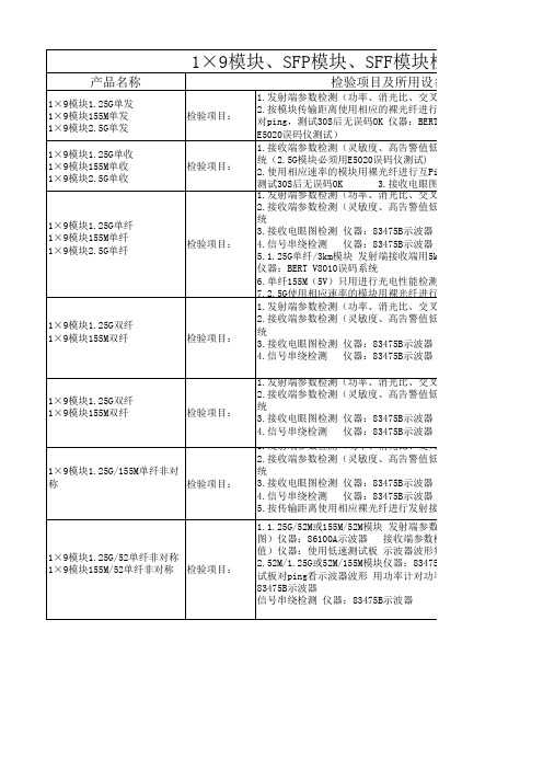
1×9模块1.25G/52单纤非对称 1×9模块155M/52单纤非对称 检验项目:
1.发射端参数检测(功率、消光比、交叉点、眼图)仪器:86100 2.接收端参数检测(灵敏度、高告警值低告警值)仪器:BERT V8 统 3.接收电眼图检测 仪器:83475B示波器 4.信号串绕检测 仪器:83475B示波器 5.按传输距离使用相应裸光纤进行发射接收视频传输 图象必须没 1.1.25G/52M或155M/52M模块 发射端参数检测(功率、消光比、交 图)仪器:86100A示波器 接收端参数检测(灵敏度、高告警值 值)仪器:使用低速测试板 示波器波形判定 2.52M/1.25G或52M/155M模块仪器:83475B示波器 发射参数检测( 试板对ping看示波器波形 用功率计对功率值 接收电眼图检测 仪 83475B示波器 信号串绕检测 仪器:83475B示波器
光比、交叉点、眼图)仪器:86100A示波器 高告警值低告警值)仪器:BERT V8010误码系 3.3V工作电 压
75B示波器 75B示波器 的核对) 接收端用5km裸光纤传输10S无误码丢包率OK
件检测:偏置电流、光功率、接收功率是否校
光比、交叉点、眼图)仪器:86100A示波器 高告警值低告警值)仪器:BERT V8010误码系
75B示波器 75B示波器 的核对) 光比、交叉点、眼图)仪器:86100A示波器 高告警值低告警值)仪器:BERT V8010误码系
3.3V工作电 压
75B示波器 75B示波器 的核对)
3.3V工作电 压
F模块检验项目
备注
及所用设备
光比、交叉点、眼图)仪器:86100A示波器 用于任何接 裸光纤进行互Ping,如25KM用30KM裸光纤进行 口类型、 仪器:BERT V8010误码系统(2.5G模块必须用 3.3V和5V模 块 高告警值低告警值)仪器:BERT V8010误码系 用于任何接 码仪测试) 口类型、 纤进行互Ping,如25KM用30KM裸光纤进行ping 3.3V和5V模 接收电眼图检测 仪器:83475B示波器 块 光比、交叉点、眼图)仪器:86100A示波器 高告警值低告警值)仪器:BERT V8010误码系 除单纤155M (5V)外用 75B示波器 于任何接口 75B示波器 接收端用5km裸光纤传输10S无误码丢包率OK 类型、3.3V 和5V模块 电性能检测、接收眼图检测、信号串绕检测 裸光纤进行互Ping必须用E5020误码仪测试 光比、交叉点、眼图)仪器:86100A示波器 高告警值低告警值)仪器:BERT V8010误码系 用于任何接 口类型、 75B示波器 3.3V和5V模 75B示波器 块
(完整word版)基于ARM系统的公交车多功能终端的设计

湖南文理学院课程设计报告课程名称:嵌入式系统课程设计专业班级:自动化10102班学号(2位)学生姓名:指导教师:完成时间: 2013年7 月1 日报告成绩:湖南文理学院制摘要 (III)一、设计题目 (7)二、设计要求 (7)三、设计的作用目的 (7)四、智能车载终端总体设计 (7)4.1主要模块基本功能介绍 (9)4。
2 模块选型 (10)4。
2.1 GPS模块 (10)4.2。
2 GPRS模块 (10)4。
2.3 语音模块 (11)4。
2。
4 液晶显示 (11)五、系统硬件设计 (12)5。
1 ARM微控制器模块 (12)5。
2时钟及复位电路 (13)5。
3 FLASH 存储器电路设计 (13)5.4 GPS模块电路设计 (14)5.5 GPRS模块电路设计 (15)六、系统软件设计 (15)6.1嵌入式操作系统的选型 (15)6。
2 配置编译内核 (16)6。
3嵌入式引导程序移植 (16)6。
4应用软件的设计 (17)6。
4。
1 Linux 下的串口编程 (17)6.4。
2 Linux 下的网络编程 (19)6。
4.3 Linux 下的多线程编程 (19)6.4。
4 各模块协作示意图 (20)七、系统调试应注意的问题 (21)八、设计总结 (21)九、参考文献 (22)摘要近年来,随着我国经济的快速发展,我国城市人口规模不断扩大,汽车保有量也逐步增长。
由此引发的城市交通问题越来越突出,如交通拥挤、交通堵塞、噪音污染、废气污染等,严重影响城市的可持续发展和居民的正常生活。
大力发展城市公共交通势在必行.智能公交系统是现代控制技术、定位技术和无线通信技术等多种技术的有机结合,它的建设可以改善公交公司的企业管理方式,提高公交系统的运营效率和服务水平,是旨在解决城市交通问题的一项根本性方案。
GPS是由美国建立的新一代卫星导航与定位系统,具有全球性、全天候、陆海空全能等特点,特别适用于交通运输行业,配合中国移动稳定可靠、覆盖面广、数据传输速度极快的GPRS网络作为信息传输的媒介,以GPS、GPRS为主要技术的智能公交系统较以往利用射频、数传电台技术方式建造的公交系统具有更加稳定、实时性更高等特点,是当前智能公交系统设计的理想方案。
一种GPS与远程服务器通信方式的研究

Microcomputer Applications V ol.27,No.2,2011研究与设计微型电脑应用2011年第27卷第2期3文章编号:1007-757X(2011)02-0023-05一种GPS 与远程服务器通信方式的研究蓝箭,李东明,于水清摘要:智能交通系统作为一项高新技术,其主要因素在于网络通信系统(NCS )及地理信息系统(GIS )的结合,所实现的远程监控系统终端采用GPRS (通用分组无线业务)加GPS (全球定位系统)架构。
基于终端处理器上的嵌入式操作系统WinCE5.0,方便的实现终端对TCP/IP 的支持以及多媒体功能应用程序的开发,最终实现了终端与服务器端的通信。
这种通信方式可广泛应用于汽车防盗,远程监控系统中。
关键词:通用分组无线业务;全球定位系统;嵌入式操作系统WinCE SDK中图分类号:TP393.05文献标志码:B0引言本文的研究重点在于定位导航终端GPS 数据的获取及其与服务器端之间的通信。
终端处理器通过RS232与GR87GPS OEM 进行通信,定时获取GPS 数据。
利用GPRS 无线拨号上网功能,实现了服务器端与终端的物理层以及逻辑链路层的连接。
通过嵌入式操作系统WinCE 对TCP/IP 的支持,实现了网络层的连接。
应用层利用WinSocket 实现终端与服务器端的通信。
1系统硬件架构1.1系统硬件平台定位导航终端采用远峰84A GPS主板,其主控图1定位导航终端系统框图制芯片采用(ARM11+DSP )架构的GPS 导航专用芯片A TLA S IV 。
该芯片标称频率为533MH Z ,带有浮点处理单元(FPU)以及图像与处理器(VPPA ),支持166MH Z 以及200MH Z 的DDR ,带有8位NAND FLASH 控制接口以及丰富的外围接口。
GPRS 模块采用BENQ23内置TCP/IP 协议的DTU 。
GPS 主板通过RS-232进行通信。
梦芯科技MXT902TL模块用户手册说明书

MXT902TL 精密授时模块用户手册Copyright © 2015-2020Wuhan Mengxin Technology Co., Ltd.修订记录版本号修订记录日期V1.0用户手册更新2020年2月免责声明本文档提供有关武汉梦芯科技有限公司产品的信息。
本文档并未以暗示、禁止反言或其他形式转让本公司或任何第三方的专利、商标、版权或所有权或其下的任何权利或许可。
除武汉梦芯科技有限公司在其产品的销售条款和条件中声明的责任之外,本公司概不承担任何其它责任。
并且,武汉梦芯科技有限公司对其产品的销售和/或使用不作任何明示或暗示的担保,包括对产品的特定用途适用性、适销性或对任何专利权、版权或其它知识产权的侵权责任等,均不作担保。
若不按手册要求连接或操作产生的问题,本公司免责。
武汉梦芯科技有限公司可能随时对产品规格及产品描述作出修改,恕不另行通知。
对于本公司产品可能包含某些设计缺陷或错误,一经发现将收入勘误表,并因此可能导致产品与已出版的规格有所差异。
如客户索取,可提供最新的勘误表。
在订购产品之前,请您与本公司或当地经销商联系,以获取最新的规格说明。
目录产品介绍 (5)1.1 产品概述 (5)1.2 主要特征 (5)1.3 应用领域 (5)1.4 性能指标 (6)1.5 模块框图 (7)PIN脚定义 (8)2.1 PIN脚示意图 (8)2.2 PIN脚功能描述 (8)硬件接口描述 (10)3.1 天线 (10)3.2 电源 (10)3.3 PPS (10)3.4 UART (10)3.5 EXTINT (10)3.6 RST_N (11)3.7 I2C (11)固件默认配置 (12)4.1 串口设置(CFGPRT) (12)4.2 消息设置(CFGMSG) (12)4.3 卫星系统设置(CFGSYS) (12)4.4 导航系统设置(CFGNAV) (13)4.5 授时输出参数配置(CFGTPO) (13)4.6 时间脉冲模式设置(CFGTPM) (13)授时特性 (15)电气特性 (16)6.1 绝对最大值 (16)6.2 运行条件 (16)6.3 工作环境 (17)机械规格 (18)硬件集成指南 (19)8.1 最小参考设计 (19)8.2 天线注意事项 (20)8.3 电源注意事项 (20)8.4 其它注意事项 (21)生产要求 (23)包装及运输 (24)10.1 包装 (24)10.2 ESD防护 (24)订购信息 (25)产品介绍1.1 产品概述武汉梦芯科技有限公司设计生产的MXT902TL 精密授时模块,基于公司完全自主知识产权的多模多频基带射频一体化芯片设计,是一款专门针对授时市场推出的精密授时模块。
斯奎特电源入口模块与电线滤波器FKHD说明书

1IEC Appliance Inlet C14 with Filter 2-Stage, Fuseholder 1-pole, Line Switch 2-poleSee below:Approvals and CompliancesC1470° CDescription- Panel mount :Screw-on mounting from front side - 4 Functions :Appliance Inlet Protection class I , Fuseholder for fuse-links 5 x 20 mm 1-pole , Line Switch 2-pole , Line-filter in standard version , 2 positions - Quick connect terminals 6.3 x 0.8 mmCharacteristics- Compact design with optimal shielding - All single elements are already wired- Plug removal necessary for fuse-link replacement - 2-stage line filter with increased attenuation With EMC-shield- Suitable for use in equipment according to IEC/UL 60950Suitable for use in medical equipment according to IEC/UL 60601-1Other versions on request- Medical version M80References Alternative: version with 1-stage filter FKHWeblinkspdf datasheet , html-datasheet , General Product Information , Distributor-Stock-Check , Accessories , Detailed request for productT echnical DataRatings IEC1 - 10 A @ Ta 40 °C / 250 VAC; 50 Hz Ratings UL/CSA 1 - 10 A @ Ta 40 °C / 125 VAC; 60 Hz Leakage Current standard < 0.5 mA (250 V / 60 Hz)Dielectric Strength> 1.7 kVDC between L-N > 2.7 kVDC between L/N-PE Test voltage (2 sec)Allowable Operation Tempe-rature-25 °C to 85 °CClimatic Category 25/085/21 acc. to IEC 60068-1IP-Protection from front side IP 40 acc. to IEC 60529Protection Class Suitable for appliances with protection class I acc. to IEC 61140TerminalQuick connect terminals 6.3 x 0.8 mm Panel Thickness S Screw: max 8 mmMounting screw torque max 0.5 Nm Material: HousingThermoplastic, black, UL 94V-0appliance inlet/-outletC14 acc. to IEC 60320-1,UL 498, CSA C22.2 no. 42 (for cold conditions) pin-temperature 70 °C, 10 A, Protection Class IFuseholder1-pole, Shocksafe category PC2 acc. to IEC 60127-6,for fuse-links 5 x 20 mm Rated Power Acceptance @ Ta 23 °C5 x 20: 1.6 W (1 pole)Power Acceptance @ Ta > 23°C Admissible power acceptance at higher ambient temperature see derating cur-vesLine Switch2-pole, non-illuminated, acc. to IEC 61058-1Technical DetailsLine FilterStandard Version, IEC 60939, UL 1283, CSA C22.2 no. 8 Technical DetailsMTBF> 1'200'000 h acc. to MIL-HB-217 FApprovals and CompliancesDetailed information on product approvals, code requirements, usage instructions and detailed test conditions can be looked up in Details about ApprovalsSCHURTER products are designed for use in industrial environments. They have approvals from independent testing bodies according to national and international standards. Products with specific characteristics and requirements such as required in the automotive sector according to IATF 16949, medical technology according to ISO 134485 or in the aerospace industry can be offered exclusively with customer-specific, individual agree-ments by SCHURTER.ApprovalsThe approval mark is used by the testing authorities to certify compliance with the safety requirements placed on electronic products. Approval Reference T ype: FKHDApproval Logo Certificates Certification Body DescriptionVDE Approvals VDE Certificate Number: 40004665UL Approvals UL UL File Number: E72928Product standardsProduct standards that are referencedOrganization Design StandardDescriptionDesigned according to IEC 60320-1Appliance couplers for household and similar general purposesDesigned according to IEC 60939Passive filters for suppressing electromagnetic interferenceDesigned according to IEC 60127-6Miniature fuses. Part 6. Fuse-holders for miniature fuse-linksDesigned according to IEC 61058-1Switches for appliances. Part 1. General requirements Designed according to UL 498Standard for Attachment Plugs and ReceptaclesDesigned according to UL 1283Electromagnetic interference filtersDesigned according to CSA C22.2 no. 42General Use Receptacles, Attachment Plugs, and Similar Wiring DevicesDesigned according to CSA C22.2 no. 8Electromagnetic interference (EMI) filters Application standardsApplication standards where the product can be usedOrganization Design StandardDescriptionDesigned for applications acc.IEC/UL 60950IEC 60950-1 includes the basic requirements for the safety of informationtechnology equipment.Designed for applications acc.IEC 60601-1Medical electrical equipment - Part 1: General requirements for basicsafety and essential performanceDesigned for applications acc.IEC 60335-1Safety of electrical appliances for household and similar purposes. Meetsthe requirements for appliances in unattended use. This includes the en-hanced requirements of glow wire tests acc. to IEC 60695-2-12 and -13. CompliancesThe product complies with following Guide LinesIdentification Details Initiator DescriptionCE declaration of conformity SCHURTER AG The CE marking declares that the product complies with the applicablerequirements laid down in the harmonisation of Community legislation onits affixing in accordance with EU Regulation 765/2008.RoHS SCHURTER AG EU Directive RoHS 2011/65/EUChina RoHS SCHURTER AG The law SJ / T 11363-2006 (China RoHS) has been in force since 1 March2007. It is similar to the EU directive RoHS.REACH SCHURTER AG On 1 June 2007, Regulation (EC) No 1907/2006 on the Registration,Evaluation, Authorization and Restriction of Chemicals 1 (abbreviated as"REACH") entered into force.White paper Glow wire test SCHURTER AG Meets the requirements of IEC 60335-1 for appliances in unattended use.This includes the enhanced requirements of glow wire tests acc. to IEC60695-2-12 and -13.Medical Equipment SCHURTER AG Suitable for use in medical equipment according to IEC/UL 60601-123Dimension [mm]Case 45Diagrams Standard versionNLPE’L’1)2)1) Line2) Load Medical version (M5)LPE’L’1)2)1) Line 2) LoadDerating Curves 1-poleA d m i s s i b l e p o w e r a c c e p t a n c e i n W a t tAmbient air temperature Ta °C4Attenuation Loss- - - - 50Ω differential mode _____ 50Ω common modeStandard version1 A2 A4 A6 A10 AMedical version (M5)1 A2 A4 A6 A10 AAll VariantsPackaging unit 10 Pcs AccessoriesDescriptionAssorted CoversRear Cover0859.0074Mating Outlets/ConnectorsCategory / DescriptionAppliance Outlet Overview completeIEC Appliance Outlet F, Screw-on Mounting, Front Side, Solder Terminal4787IEC Appliance Outlet F, Snap-in Mounting, Front Side, Solder or Quick-connect Terminal4788IEC Appliance Outlet F or H, Screw-on Mounting, Front Side, Solder, PCB or Quick-connect Terminal5091Appliance Outlet further types to FKHDConnector Overview complete4782 Mounting: Power Cord, 3 x 1 mm² / 3 x 18 AWG, Cable, Connector: IEC C1347824785 Mounting: Power Cord, 3 x 1 mm² / 3 x 18 AWG, Cable, Connector: IEC C1347854300-06 Mounting: Power Cord, 3 x 1 mm² / 3 x 18 AWG, Cable, Connector: IEC C134300-06IEC Connector C15 for hot conditions 120°C, Rewireable, Straight4781IEC Connector C15 for hot conditions 120°C, Rewireable, Angled4784Connector further types to FKHD...The specifications, descriptions and illustrations indicated in this document are based on currentinformation. All content is subject to modifications and amendments. Information furnished is believed18.12.2185。
基于51单片机的GPS定位系统

摘要全球定位系统(GPS)是由美国国防部开发的一种先进的无线电导航系统。
该系统能够全天候、全方位的为海陆空用户提供连续的、高精度的三维坐标、三维速度和时间等信息。
它所具有的诸多优点是其他导航设备所无法比拟地。
现在,GPS 接收机作为一种先进的导航和定位仪器,已在军事及民用领域得到广泛的应用。
本设计详细介绍了一种成本低又能满足性能使用要求的经济型GPS接收机的设计方案。
此方案基于单片机、GPS模块和1602液晶显示屏等硬件 , 并应用C语言实现了 GPS 信号的提取、显示及基本的键盘控制操作等。
经过实践测试 ,这种接收机可以达到基本 GPS信息接收以及显示,可以做到体积小、精度高、连续导航,并可广泛应用于个人野外旅游探险、出租汽车定位及海上作业等领域。
关键词: GPS;单片机;上位机;LCD1602ABSTRACTGlobal Positioning System(GPS) is the most advanced radio navigation system which was developed by the U.S Department of Defence. The system can be used under any weather conditions, all day long and anywhere on the earth. It can provide land, marine and airborne user with continuous, highly accurate three-dimension position, velocity, time dataetc. It has various advantages that are unexampled other kind of navigation equipment. Now GPS receivers, as a type of advanced equipment on navigation and positioning, have been widely used in both military and civil field.This design introduced in detail one kind of low-cost economy GPS receiver's design proposal which can satisfy the performance operation requirements .This plan is based on single chip computer、GPS and 1602 liquid crystal display monitors, and has realized the GPS signal extraction, the demonstration and the basic keyboard control operation and so on using the C language. By practical measurement, the receiver can achieve GPS information receive and display. It has small size and low cost, can be used in wild adventure tourism, taxi positioning and operations at sea.KEY WORDS:GPS; MCU;PC; LCD1602目录前言 (3)第1章GPS系统简介及设计方案选择 (4)1.1 GPS系统简介 (4)1.1.1 GPS由来及发展 (4)1.1.2 GPS定位基本原理 (4)1.1.3 GPS接收机定位流程 (4)1.1.4 任务的描述 (5)1.2 设计方案选择 (6)1.2.1 方案一 (6)1.2.2方案二 (6)第2章系统硬件设计 (7)2.1单片机 (7)2.2 GPS模块 (7)2.2.1 概述 (12)2.2.2 主要技术参数................................ 错误!未定义书签。
885nm 光纤耦合激光二极管模块

885nm 光纤耦合激光二极管模块1.这款激光二极管模块适用于光纤耦合系统。
This laser diode module is suitable for fiber-coupled systems.2.具有高功率输出和窄线宽的特点。
It features high power output and narrow linewidth.3.适用于激光雷达、光通信和科学研究等领域。
It is suitable for laser radar, optical communication, and scientific research.4.该模块可以提供稳定的光束和可靠的性能。
The module can provide stable beam and reliable performance.5.采用先进的温控和驱动技术,具有较长的寿命。
It adopts advanced temperature control and driving technology, and has a long lifespan.6.适用于要求高精度和稳定性的应用场合。
It is suitable for applications that require high precision and stability.7.紧凑的设计方便集成到各种设备中。
The compact design facilitates integration into various devices.8.具有优异的光电转换效率和低功耗特性。
It has excellent photoelectric conversion efficiency and low power consumption.9.该模块可定制不同的波长和输出功率。
The module can be customized for different wavelengths and output powers.10.适用于需要远距离传输和高速数据传输的场合。
浅谈西门子信号机
浅谈西门子信号机摘要:对于使用西门子地铁信号系统中,信号机是一个相当复杂的设备,它是进路的基本要素之一,是信号系统中的重要组成部分,在使用维护过程中常碰到比较复杂的电路故障,因此对其进行深入的探讨,总结其核心技术理论。
Abstract: to use Siemens subway signal system, signal controller is a fairly complex equipment, it is the way one of the basic elements of signal system is an important part of, in use process maintenance in the complexity of the encounter circuit failure, so to further discussion, and to sum up the core technology theory.关键词ATS列车自动监督SICAS本门子计算机联锁系统LOW 本地操作员工作站ESTT 信号接口柜LISTE信号机接口模块SISIG 信号机保险模块GRUMO信号控制单元(红灯点灯模块)FAHRMO 信号控制单元(黄灯/绿灯点灯模块)RM 限制人工驾驶模式URM 非限制人工驾驶模式一、概述信号机是铁道信号联锁的基本要素之一,是信号系统的重要组成部分,本文主要基于深圳地铁一号线使用的西门子信号机,它与国产信号机有相当大的区别,经过长期对此信号机的维护,摸索.从它的显示,点灯,灯丝转换,监测方面把此信号机的分散的资料进行了整合,把拢统的概念进行了细化,以便更好来理解,分析该信号机的设计理论,电路原理,更好维护该种类型信号机,处理信号机的故障。
二、信号机介绍1 信号机的显示西门子信号机共有4种显示:红灯:禁止列车越过该信号机黄灯:允许列车越过该信号机,表示进路上至少有一组道岔开通侧向位置绿灯:允许列车越过该信号机,表示进路上所有道岔都开通直向位置红灯+黄灯:引导信号,允许列车以RM或者URM模式越过该信号机2信号机的命令第一种命令:常规命令(1)关单信号。
- 1、下载文档前请自行甄别文档内容的完整性,平台不提供额外的编辑、内容补充、找答案等附加服务。
- 2、"仅部分预览"的文档,不可在线预览部分如存在完整性等问题,可反馈申请退款(可完整预览的文档不适用该条件!)。
- 3、如文档侵犯您的权益,请联系客服反馈,我们会尽快为您处理(人工客服工作时间:9:00-18:30)。
GR-87 GPS Receiver Module1. Main Featurez Build on high performance SiRF StarIII chipset. z Average Cold Start time and under 45 seconds. z Low power consumptionz 20 channels “All-in-View” tracking.z 200,000+ effective correlators for fast TTFF and high sensitivityacquisitionsz Integrated ARM7TDMI CPU with software engineering services andavailable for embedded customer defined applications. z On chip 1Mb SRAM.z Dual TTL level serial ports with one for GPS receiver command messageinterface, another one for RTCM-104 DGPS input.z Compact Board Size 1”x1”x0.27”(25.4x25.4x7mm) for easy integrationinto hand-held device.z Reacquisition Time 0.1 secondsz Support Standard NMEA-0183 and SiRF Binary protocolz Support Accurate 1PPS Output Signal Aligned with GPS Timing zMulti-path Mitigation Hardwarez On-board RTCM SC-104 DGPS and WAAS /EGNOS Demodulator z Built-in a lithium battery make GPS fast positioning2. Technical Specifications2.1. Electrical Characteristics2.1.1 General1). Frequency:L1, 1575.42 MHz. 2). C/A code:1.023 MHz chip rate. 3). Channels:20.2.1.2 Accuracy (Open Sky)1). Position:10 meters, 2D RMS.2). 7 meters 2D RMS, WAAS corrected.3). 1-5 meters, DGPS corrected.4). Altitude :< ± 35m Vertical in term of 95%.5). Velocity:0.1 meters/second.6). Time 1 microsecond synchronized to GPS time.2.1.3 Datum1). Default:WGS-84.2). Other Support different datum by request.2.1.4 Acquisition Rate (Open sky, stationary requirements)1). Reacquisition:0.1 sec., average. 2). Hot start: 1 sec., average. 3). Warm start:38 sec., average. 4). Cold start:42 sec., average.2.1.5 Dynamic Conditions1). Altitude : 18,000 meters (60,000 feet) max.2). Velocity:515 meters/second (1000 knots) max. 3). Acceleration:4g, max.4). Jerk:20 meters/second, max.2.1.6 Power1). Input power input:3.3 ~ 5.5 VDC input.2). Input current: Less than 80 mA (without antenna) .3). Backup power: 3V Rechargeable Lithium cell battery, up to 500 hours discharge.2.1.7 RF interface1). Antenna connector type: MMCX, output 2.8 VDC. (optional outputVCC_IN)2). Minimum signal tracking: -159 dBm.2.1.8 Serial Port1). Two full duplex serial communication, CMOS interface, with userselectable baud rate (4800-Default, 9600, 19200, 38400). 2). NMEA 0183 Version 2.2 ASCII output (GGA, GSA, GSV, RMC (VTG ,GLL and ZDA for optional)).3). DGPS protocol RTCM SC-104 message types 1, 2 and 9. 4). SiRF binary-position, velocity, altitu de, status output.2.1.9 TIMEMARK-1PPS Pulse1). Level CMOS 3V.2). Pulse duration 1 microsecond.3). Time reference At the pulse positive edge.4). Measurements Aligned to GPS second, ±1 microsecond.2.2. Environmental Characteristics1). Operating temperature range -10 ℃ to +60 ℃. 2). Storage temperature range -20 ℃ to +85 ℃. .2.3. Physical Characteristics1) Active Size: 25.4(W) x 25.4(D) x 7(H) (mm) . 2) Weight: 2 g.3) Interface connector 6-pin straight male header, 1.25 mm pitch .3. Mechanical Dimensions3.1 . GR-87-T0A, GR-87-T0C outline:略3.2 . GR-87-T0B, GR-87-T0D outline:略3.3. Pin assignment of connector :Table 4-1 is pin list of the 6-Pin Interface Connector. Connector is Male header 1.25mm pitch DIP R/A type. Actual pin size see appendix B.Table 4-1 J1 connector pin definition:PinPin NameFunction description1 VCC_5V +3.5~5.5VDC power input2 TXASerial Data output port A(CMOS Level: Voh2.4V ≧Vol0.4V Ioh=Iol=2mA)≦3 RXASerial Data input port A(CMOS Level Vih≧0.7*VCC Vil≦0.3*VCC)4 RXBSerial Data input port B(CMOS Level Vih≧0.7*VCCVil≦0.3*VCC)5 GND Power ground6 TIMEMARK/ RESET (option)TIMEMARK: 1PPS Time mark output(Vil≦0.2V PulseWidth 1 usec).RESET: Reset Input (Active Low)(option function)3.3.1 VCC_5VThis is the main DC power supply for a +3.3~ 5.5 V engine board.3.3.2 TXAThis is the main transmitting channel and is used to output navigation and measurement data for user written software.3.3.3 RXAThis is the main receiving channel and is used to receive software commands to the board from u ser written software.3.3.4 RXBThis is the auxiliary receiving channel and is used to input differential corrections to the board to enable DGPS navigation.3.3.5 GNDGND provides the ground for the board. Connect all grounds.3.3.6 TIMEMARK (default)/ RESET (option)This pin default is provides 1 pulse per second output from the GR-87 engine board, which is sync hronized to within 1 microsecond of GPS time. The output is a CMOS 3V positive level signal. Only upon a situation of tracking or navigating will output once per second. This is not available in Tri ckle-Power mode.The secondary option function is provides an active-low reset input to the engine board. It causes the engine board to reset and start searching for satellites. (This second function setting need co ntact factory).4. Ordering Information。