R1966ABLKBLKESYEL;中文规格书,Datasheet资料
博布里克洗手间设备产品数据手册说明书

The manufacturer reserves the right to, and does from time to time, make changes and improvements in designs and dimensions. © 2008 by Bobrick Washroom Equipment, Inc.materialS:Stiles c—3/4'' (19mm) thick, Solid Color Reinforced Composite with GraffitiOff ™ surface thermoset and integrally fused into one homogenous piece. Surface, edge, core are to be the same color. Leveling device: 7 gauge, 3/16" (5mm) thick, corrosion-resistant, chromate-treated, double zinc-plated steel angle leveling bar bolted to stile; furnished with 3/8'' (10mm) stainless steel diameter threaded wedge anchor, hex nuts, lock washer, flat washers, and shoe retainers. Shoe: 18-8 S, type-304, 22-gauge (0.8mm) stainless steel with satin finish; 4'' (102mm) high.Panels —1/2'' (13mm) thick, Solid Color Reinforced Composite with GraffitiOff ® surface thermoset and integrally fused into one homogeneous piece. Surface, edge, core are to be the same color.doors —3/4'' (19mm) thick, Solid Color Reinforced Composite with GraffitiOff ® surface thermoset and integrally fused into one homogeneous piece. Surface, edge, core are to be the same color.Posts (for 1093 Series screens only) — 1-1/4'' (32mm) square tubing; 18-8 S, type-304, 18-gauge (1.2mm) stainless steel with satin finish. Floor and ceiling connections are constructed of 18-8 S, type-304, heavy-gauge stainless steel. Furnished in 10-ft (305-cm) lengths; to be cut in field to job specifications.Headrail (for 1092 Series compartments only) —Extruded anodized aluminum with satin finish. Enclosed construction with sloping top. Face has raised grip-resistant edge.Designer's Notes: Headrails with integral curtain tracks and hooks are available for compartments without doors. Optional vinyl curtains are available.Wall Posts —1" x 1-1/2" (25 x 38mm) tubing; 18-8 S, type-304, 16-gauge (1.6mm) stainless steel with satin-finish. 58" (147cm) high, pre-drilled for door hardware.Heavy-duty Hardware (standard) — Hinges, door latches, door keepers, clothes hooks, door stop plates, and mounting brackets are constructed of 18-8 S, type-304, heavy-gauge stainless steel with satin finish. Threaded inserts are factory installed for securing hinges, door stop plates, and door latches. Theft-resistant, stainless steel pin-in-head Torx screws are furnished for door hardware and all mounting brackets. Barrel hinge is adjustable to adjust door swing of unoccupied toilet compartment from partially open to fully closed. Toilet compartment door is locked from inside by sliding door latch into keeper. Threaded inserts are factory installed to secure door hinges, latch and door stops. Two door stops prevents door from being kicked in/out beyond stile by vandals. Mounting screws for stile to panel bracket, latch keeper, and coat hook connections are through-bolted.institutional Hardware (.67 option) —Hinges, door latches, door keepers, clothes hook, U-channels, door stop plates and angle brackets are constructed of 18-8 S, type-304, heavy-gauge stainless steel with satin finish: one-piece, full-height hinge is 16 gauge (1.6mm); one-piece door keeper is 11 gauge (3.2mm);one-piece, full-height U-channels and angle brackets are 18 gauge (1.2mm). U-channels secure panels to stiles, and angle brackets secure panels and stiles to walls. Door latch slides on a shock-resistant nylon track. Two door stops prevent door from being kicked in/out beyond stile by vandals. Theft-resistant, stainless steel pin-in-head Torx screws are furnished for door hardware, U-channels, and angle brackets. Doors are equipped with a self-closing hinge. Threaded inserts are factory installed to secure door hinge, latch, and doorstops. Mounting screws for stile-to-panel brackets and latch keeper connections are through-bolted. To specify institutional hardware, add suffix .67 to series number. Example: specify 1092.67 for overhead-braced partitions furnished with institutional hardware, including factory-installed threaded inserts for door hardware attachment.inStallation:Bobrick installation instructions are packed with each shipment and are available also in advance on request.notes:1. Ceiling-hung and floor-to-ceiling toilet compartments require structural members (not furnished by Bobrick) in ceiling. For suggested types of ceiling supportsystems, see Bobrick Advisory Bulletin TB-32.2. Wall backing is required to secure the mounting brackets of panels, stiles, and wall posts. For suggested wall backing, see Bobrick Advisory Bulletin TB-46.3. Floor-anchored stiles are furnished with expansion shields and threaded rods. The expansion shields require minimum 2'' (50mm) penetration into minimum3'' (75mm) thick structural concrete.4. Bobrick stainless steel partition-mounted washroom accessories are available for mounting in panels between two compartments. See current Bobrick Catalogfor description of accessories. Cutouts in panels can be pre-cut for Bobrick models at factory if location and size of all cutouts and Bobrick model numbers are furnished at time of order.GUarantee:Bobrick toilet partitions including all hardware and mounting brackets are guaranteed to be free from defects in material and workmanship for a period of one year from date of purchase. Any products returned to Bobrick under this guarantee will be repaired or replaced at no charge. 10-Year Warranty: Bobrick ex-tends a ten-year limited warranty from date of purchase for SierraSeries® Solid Color Reinforced Composite partition panels, doors, and stiles against breakage, warpage, delamination and corrosion when materials are properly installed, and normally used.SpeCiFiCation:Water-resistant, solid color reinforced composite ____________________ (insert one: toilet partitions, dressing compartments, shower dividers, urinal screens) shall be _______________ (insert one: overhead-braced toilet partition or floor anchored, wall-hung, post-to-ceiling urinal screens). Stiles, panels and doors shall be constructed of Solid Color Reinforced Composite with GraffitiOff ® surface thermoset and integrally fused into one homogeneous piece. Surface, edges and core are to be same color. Solid Color Reinforced Composite material shall be covered by a 10-year limited warranty against breakage, warpage, corrosion, and delamination. Stiles and doors shall be 3/4'' (19mm) thick; panels shall be 1/2'' (13mm) thick. All units shall meet ICC and NFPA Class B or UBC Class II, ASTME 84 Fire-Resistance Standards. Stiles shall have leveling device that is concealed by a one-piece, type-304, satin-finish stainless steel shoe that is 4'' (102mm) high.Stiles, panels and doors shall be __________ (insert color name and number from current Bobrick catalog). Headrails for overhead-braced compartments shall be anodized aluminum with satin finish. **All door hardware and mounting brackets shall be type-304 stainless steel with satin finish. All doors shall be supplied with three hinges. Threaded inserts shall be factory installed for securing door hinges, latches and door stops. Theft-resistant, stainless steel pin-in-head Torx screws shall be furnished for door hardware and all mounting brackets. Through bolts shall be used for securing latch keeper, clothes hook and panel-to-stile brackets. A clothes hook shall be furnished for each door with heavy duty hardware option. Hinges shall be adjustable to hold doors of unoccupied compartments partially open or fully closed. Two door stops shall be furnished for each door to prevent it from being kicked in/out beyond stile by vandals. Manufacturer's service and parts manual shall be provided to the building owner/manager upon completion of project.**To specify Institutional hardware, replace end of specification paragraph with: .67 option All door hardware, U-channels, and angle brackets shall be type-304 stainless steel with satin finish: one-piece, full-height hinges shall be 16 gauge (1.6mm); one-piece door keepers shall be 11 gauge (3.2mm); one-piece, full-height U-channels and angle brackets shall be 18 gauge (1.2mm). U-channels shall be furnished to secure panels to stiles, and angle brackets furnished to secure panels and stiles to walls. Doors shall be equipped with a self-closing hinge. Two door stops shall be furnished for each door to prevent it from being kicked in/out beyond stile by vandals. A clothes hook shall be furnished for each door. Theft-resistant, stainless steel pin-in-head, Torx screws shall be furnished for door hardware, U-channels, and angle brackets. Through bolts shall be used for securing latch keeper and panel- to-stiles brackets. Threaded inserts shall be factory installed to secure all door hinges, latches, and doorstops. Manufacturer's service and parts manual shall be provided to the building owner/manager upon request._________________ (insert one: toilet Partitions, dressing Compartments, Shower dividers, Urinal Screens) shall be ____________________ Series (insert series number) of Bobrick Washroom equipment, inc., Clifton Park, new York; Jackson, tennessee; Los Angeles, California; Bobrick Washroom equipment Company, Scarborough, ontario; Bobrick Washroom equipment Pty. Ltd., Australia; and Bobrick Washroom equipment Limited, United Kingdom.The illustrations and descriptions herein are applicable to production as of the date of this Technical Data Sheet. 1090 Revised 8/08 Printed in U.S.A. The manufacturer reserves the right to, and does from time to time, make changes and improvements in designs and dimensions. © 2008 by Bobrick Washroom Equipment, Inc.。
海利拜利公平磨损标准指南说明书

Fair Wear and Tear Guidelines.Hyundai Fair Wear and Tear Guidelines.This document should be read in conjunction with your Hyundai Finance™ Fixed Rate Loan Agreement with the “Guaranteed Future Value” details.This guide will provide you with examples of acceptable and unacceptable wear and tear which will form the standard by which your vehicle will be assessed and can be used as a guide to help you keep your vehicle in an acceptable condition.Fair wear and tear is the wear and tear that can be reasonably expected in the life of a vehicle that is properly maintained and cared for. Unacceptable wear and tear may occur when faults and damage are unrepaired or poor quality repairs are undertaken. Unacceptable wear and tear may also occur when the manufacturer’s recommended maintenance and servicing schedules are not followed and/or ongoing maintenance of the vehicle does not occur.If the fair wear and tear requirements are not met in accordance with the acceptable standards set out in this Guideline, an adjustment to your Guaranteed Future Value will apply.AppearanceAt the end of the finance contract period, the vehicle should be made available in a suitably clean condition to allow for proper inspection of the paint, body and interior.Additional equipmentAccessories such as car telephones that have been installed are to be removed, and any holes or damage should be made good to a professional standard.All standard equipment, together with non-standard or ‘customised’ fittings originally supplied, must be returned with the vehicle at the end of the finance contract period. If these fittings are not returned, an adjustment to your Guaranteed Future Value would apply.Badges and labelsN on-standard badges, labels or advertising fitted to the bodywork or glass of the vehicle should be removed, with any damage caused by their attachment or removal rectified. If the attachment of advertising results in paintwork fading an adjustment to your Guaranteed Future Value will apply. Advertising should never be painted directly onto the vehicle.Keys and securityA full set of keys should be available and should be functioning. The return of the master key which controls the vehicle’s engine management system is mandatory.If the vehicle was originally supplied with a security system, this should be intact and fully operational,including any key or key fob necessary for operation. Any additional, non-standard security system should be fitted according to a recognised standard. Failure to supply the full set of keys and/or damage to any security system will result in an adjustment to your Guaranteed Future Value.Vehicle servicingRegular maintenance and servicing should be carried out by an authorised Hyundai dealer or a suitably qualified motor vehicle repairer according to the manufacturer’s guidelines. Approved parts and lubricants must be used at all times.The following examples are conditions usually caused by mechanical neglect or misuse and therefore are not regarded as fair wear and tear.• Grooved brake discs caused by metal to metal contact•E ngine seized due to running the vehicle with insufficient coolant, lubricating oil and with broken internal components • T ransmission slipping, erratic gear changing, clutch slipping, noisy transmission or ineffective synchromeshYour completed vehicle service and Hyundai warranty booklets along with any documentation relating to vehicle equipment must remain in the vehicle upon return – including any details of radio codes.Fair Wear and Tear explainedMaintenance requirementsVehicle exterior Vehicle interiorAcceptableP aintwork. Small areas of stonechipping, door edge chipping and lightscratches (up to 25mm in length) areacceptable, relative to the vehicle’s age and mileage, as long as they have notpenetrated through to the base metaland caused corrosionM inor dents are acceptable as longas the paint surface has not beenpenetrated through to the metal orcorrosion has set inA ny damage must be repaired as andwhen it occurs. All work should becompleted to a professional standard,with any applicable anti-corrosionguarantees taken into considerationMinor paint touch ups or flakingB umper and rubbing strips. Providedthese are not broken, cracked ordeformed a limited amount of scuffingand score marks is acceptableW indow glass damage if relativelyminor and repaired using resinimpregnation to motor registrystandards is acceptable. Lightscratches and minor chipping aroundthe periphery of the windscreen isaccepted as fair wear and tear. Thewindscreen must be able to pass aroadworthy inspectionAcceptableI nterior trim should be clean and tidywith no visible burns, tears or permanentstaining to the seats, headlining orcarpets. Wear and soiling through normaluse is acceptable, as are any repairs thatare not readily visibleA reasonable amount of scuffing to thedoor and luggage area treads and sills isacceptable providing paintwork has notbeen damaged down to bare metal andaperture seals are not tornS urface scoring and light blemishes inthe luggage area that reflect normal useare acceptable but floor coverings andsurrounding trim panels should not betorn or splitF or light commercial vehicles it isrecommended that a lining be fitted inthe load area to prevent serious damageto the vehicle’s interior, as excessivedamage to this area is unacceptableUnacceptableD ents greater than 20mm in diameter2 or more dents occurring on a single panel(no matter how small) is unacceptable,and the panel should be repaired orreplacedA brasions/scratches more than 25mm inlengthC olour mismatch between panels, orpoorly fitting panels, are unacceptableP rominent paint touch ups or major paintflakingP anel rustP oor paint/panel repairsS poils from bird/tree droppingsE xterior damage caused by theattachment/removal of stickers/decalsD amage resulting from hailB ody buckling, distortions or missingvehicle badgesW indow cracks or damage within thedriver’s sight line is not acceptableC racked lamp glass/lens is notacceptable. Lamps must be operationalH oles caused by the removal ofaccessoriesU nrepaired or poorly repaired aerial holes(or aerial must be left in place)UnacceptableS titching that has come apart isunacceptable and needs to be repairedB urns, tears or permanent staining to theseats, headlining or carpetsT ears and splits to the trim panels, floorcovering and liningsDamage to the seat structureUnauthorised odometer changesMissing controls/accessoriesH oles caused by the removal ofaccessoriesD amage to vehicle rubber seals as aresult of neglect or misuseA guide to Acceptable and Unacceptable Fair Wear and Tear.Finance to approved applicants only. Credit criteria, fees, charges and T&Cs apply.Finance is provided by Allied Retail Finance Pty Ltd trading as Hyundai Finance ABN 31 609 859 985Australian Credit License 483211.Hyundai Finance is the registered business name of Hyundai Motor Company Australia Pty Ltd ABN 58 008 995 588.。
拜科奇产品手册

目录
.1 . . . . . .1 .1.1 .1. .1. .1. .1. . ..1 .. .1 . . . . . . . 10 11
拜科奇的产品特性 ......................................................................................................... 质量保证........................................................................................................................ 产品纯度........................................................................................................................ 耐受性和安全性的临床前证据 ....................................................................................... 临床前免疫原性模型...................................................................................................... 临床前疗效研究............................................................................................................. 拜科奇临床前研究小结 .................................................................................................. 临床研究........................................................................................................................ 对既往接受过治疗的患者(PTPs)的研究.................................................................... 0 药代动力学 .................................................................................................................... 0 疗效............................................................................................................................... 临床免疫原性 ................................................................................................................ 外科手术中的应用 ......................................................................................................... 安全性 ........................................................................................................................... 对既往未接受过治疗(PUPs)或仅接受过最低限度治疗(MTPs)的患者的研究 ....... 拜科奇用于治疗PUPs/MTPs的安全性及疗效 ................................................................ PUPs/MTPs中抑制物的产生率...................................................................................... 重组人凝血因子VIII抑制物的形成.................................................................................. 1 抑制物形成的潜在标志物 .............................................................................................. 1 抑制物形成的发生率...................................................................................................... 抑制物分子 ................................................................................................................... 抑制物的特异性............................................................................................................. 对PTPs的临床免疫原性研究 ......................................................................................... PUPs/MTPs中抑制物发生率的比较 ............................................................................. 抑制物产生的累积风险 .................................................................................................. 0 小结:拜科奇与凝血因子VIII抑制物 .............................................................................. 1 免疫耐受诱导 (ITI) ........................................................................................................ 长期预防........................................................................................................................ 产品亮点总结 ................................................................................................................ 0 参考文献........................................................................................................................
19665;中文规格书,Datasheet资料

Dual-Wire Dual-Operator Programmable Monitor DescriptionThe patented* Desco Dual-Wire Dual-OperatorProgrammable Monitor monitors two operators and two ESD work worksurfaces eliminating the need for periodic Figure 1. Desco 19665 Dual-Wire Dual-Operator Programmable MonitorFeatures and ComponentsTECHNICAL BULLETIN TB-3019Made in theUnited States of AmericaFigure 2. Dual-Wire Dual-Operator Programmable CBDE FG H I J K LFRONT VIEWBACK VIEWOperation1. Monitoring of the operators will remain in the STANDBY condition until a wrist cord is plugged into the operator remote. STANDBY mode is indicated by a blinking yellow operator LED.10mm snap needs to pierce and clinch bottom side of mat. Snap needs to be at least 12" apart or 72" max. 10mm snap needs to pierce and clinch bottom side of mat. Snap needs to be at least 12" apart or 72" max.OPERATOR 1WORKSURFACEOPERATOR 2WORKSURFACE10mm PUSH & CLINCH SNAP10mm PUSH & CLINCH SNAPBENCH GROUNDMAT 1 WIRING WHITE CABLEMAT 2 WIRING BLACK CABLEWRIST STRAP MONITORWRIST STRAP MONITORELECTRIC GROUNDOPERATOR 2REMOTE JACK BLACK CABLEOPERATOR 2REMOTE JACK WHITE CABLE Screw allows ground cord to be bolted to mat; keeps cord from disconnecting.Figure 3. Installing the Dual-Wire Dual-Operator Programmable MonitorororFigure 4. Connecting a dual-wire wrist strap to the operator remoteSETTING THE OPERATOR TEST VOLTAGE AND TEST LIMITThe Dual-Wire Dual-Operator Monitor’s operator test voltage and high test limit can be set to different values. The operator test voltage can be set to either +5V or +8V, and the operator high test limit can be set to either 10 megohms or 35 megohms. The default voltage is +8V, and the default operator high test limit is 10 megohms. These settings are controlled by a set of 3 switches located inside the monitor’s enclosure.NOTE: Desco recommends re-calibration of the monitor should either setting be changed. See the “Calibration” section for more information.To gain access to these switches, remove the monitor’s cover and position the monitor so the PCB matches the orientation shown in Figure 5. Switches SW1 and SW2 control the operator test voltage. Switch SW3 controls the operator high test limit.Operator Test Voltage+5VSW1 Position: RIGHTSW2 Position: LEFT+8VSW1 Position: LEFTSW2 Position: RIGHTOperator High Test Limit10 megohmsSW3 Position: RIGHT35 megohmsSW3 Position: LEFTCalibrationFrequency of recalibration should be based on the critical nature of those ESD sensitive items handled and the risk of failure for the ESD protective equipment and materials. In general, Desco recommends that calibration be performed annually.Use the EMIT 50524 Limit Comparator for Dual-Wire Monitors to perform periodic testing (once every 6-12 months) of the Dual-Wire Dual-Operator Programmable Monitor. The Limit Comparator can be used on the shop floor within a few minutes virtually eliminating downtime, verifying that the monitor is operating within tolerances. See TB-6542 for more information.Figure 5. Switches SW1, SW2 and SW3 inside the monitor’s enclosure Figure 6. EMIT 50524 Limit Comparator for Dual-Wire MonitorsNIST CalibrationDesco provides a basic, National Institute of Standardsand Technology (NIST) traceable calibration for theproducts that we manufacture. This is sometimesreferred to as a Level 1 calibration.For more on National Institute of Standards andTechnology see:/index.htmlFor more information on the calibration that Desco’sprovides for products that we manufacture see:/Calibration.aspxSpecificationsOperating Voltage 12 VDCOperating Temperature 32°F - 104°F (0 - 40°C)Monitor Dimensions 4.4" x 4.7" x 2.1"(11.2cm x 11.9cm x 5.3cm)Monitor Weight 1.1 lbs (0.5 kg)TEST VOLTAGESOperator +8 V** or +5 VWorksurface 200 mVTEST LIMITSOperator Low Fail: < 1.72 megohmsPass: 2 - 9 megohms**High Fail: > 11.5 megohms**orPass: 2 - 30 megohmsHigh Fail: > 40 megohmsWorksurface Pass: < 3.5 megohmsFail: > 3.8 megohms**DefaultFigure 7. Operator Remote dimensionsReplacement remotes are available as EMIT itemnumbers 50525 and 50526.分销商库存信息: DESCO19665。
3336-52;3336-01;中文规格书,Datasheet资料
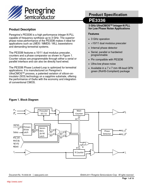
©2005-2011 Peregrine Semiconductor Corp. All rights reserved. Page 2 of 13
Document No. 70-0033-05 │ UltraCMOS™ RFIC Solutions
/
PE3336
Product Specification
/
PE3336
Product Specification
Figure 2. Pin Configurations (Top View)
GND GND GND
48 47 46 45 44 43 42 41 40 39 38 37
D0, M0 D1, M1 D2, M2 D3, M3 VDD VDD S_WR, D4, M4 Sdata, D5, M5 Sclk, D6, M6 FSELS, D7, Pre_en GND FSELP, A0
3 GHz operation ÷10/11 dual modulus prescaler Internal phase detector Serial, parallel or hardwired
programmable
Pin compatible with PE3236 Ultra-low phase noise Available in a 7 x 7 mm 48-lead QFN
Table 1. Pin Descriptions (continued)
Pin No. Pin Name S_WR 7 D4 M4 Sdata 8 D5 M5 Sclk 9 D6 M6 FSELS 10 D7 Pre_en 11 GND FSELP 12 A0 Direct Serial E_WR 13 A1 M2_WR 14 A2 Smode 15 A3 16 17,18 19 20 21 22 Bmode VDD M1_WR A_WR Hop_WR Fin Direct ALL ALL Parallel Parallel Serial, Parallel ALL Input Input (Note 1) Input Input Input Input Direct Serial, Parallel Input Input Parallel Direct Parallel Input Input Input Enhancement register write. D[7:0] are latched into the enhancement register on the rising edge of E_WR. A Counter bit1. M2 write. D[3:0] are latched into the primary register (R[5:4], M[8:7]) on the rising edge of M2_WR. A Counter bit2. Selects serial bus interface mode (Bmode=0, Smode=1) or Parallel Interface Mode (Bmode=0, Smode=0). A Counter bit3 (MSB). Selects direct interface mode (Bmode=1). Power supply input. Input may range from 2.85 V to 3.15 V. Bypassing recommended. M1 write. D[7:0] are latched into the primary register (Pre_en, M[6:0]) on the rising edge of M1_WR. A write. D[7:0] are latched into the primary register (R[3:0], A[3:0]) on the rising edge of A_WR. Hop write. The contents of the primary register are latched into the secondary register on the rising edge of Hop_WR. Prescaler input from the VCO. 3.0 GHz max frequency. ©2005-2011 Peregrine Semiconductor Corp. All rights reserved. Page 3 of 13 Input Input Parallel Direct ALL Parallel Input Input Input Parallel Direct Serial Input Input Input Parallel Direct Serial Parallel Direct Serial Input Input Input Input Input Input Interface Mode Serial Type Input Description Serial load enable input. While S_WR is “low”, Sdata can be serially clocked. Primary register data are transferred to the secondary register on S_WR or Hop_WR rising edge. Parallel data bus bit4 M Counter bit4 Binary serial data input. Input data entered MSB first. Parallel data bus bit5. M Counter bit5. Serial clock input. Sdata is clocked serially into the 20-bit primary register (E_WR “low”) or the 8-bit enhancement register (E_WR “high”) on the rising edge of Sclk. Parallel data bus bit6. M Counter bit6. Selects contents of primary register (FSELS=1) or secondary register (FSELS=0) for programming of internal counters while in Serial Interface Mode. Parallel data bus bit7 (MSB). Prescaler enable, active “low”. When “high”, Fin bypasses the prescaler. Ground. Selects contents of primary register (FSELP=1) or secondary register (FSELP=0) for programming of internal counters while in Parallel Interface Mode. A Counter bit0 (LSB). Enhancement register write enable. While E_WR is “high”, Sdata can be serially clocked into the enhancement register on the rising edge of Sclk.
IL66中文资料

Comparative Tracking Index..............................175
Isolation Resistance VIO=500 V, TA=25°C................................≥1012 Ω VIO=500 V, TA=100°C..............................≥1011 Ω
10 ° Typ.
.008 (.20) .012 (.30)
.115 (2.92) .135 (3.43)
5–1
元器件交易网
Electrical Characteristics (TA=25C)
Symbol
Min. Typ.
GaAs Emitter
Forward Voltage
VF - Forward Voltage - V
1.3
Ta = -55°C
1.2 Ta = 25°C
1.1
1.0
0.9
Ta = 100°C
0.8
0.7
.1
1
10
100
IF - Forward Current - mA
Figure 2. Normalized non-saturated and saturated CTRce versus LED curren
Storage Temperature ................... –55°C to +125°C Operating Temperature................ –55°C to +100°C Lead Soldering Time at 260°C ....................10 sec.
KellyKBLI_KHB_HPUserManualcn
表 1: LED 错误代码 ..................................................................................................... 22
联系我们:........................................................................................................................ 25
2
凯利 KBLI/KHB/HP 系列大功率无刷电机控制器用户手册
版本 3.3
第一章 概述
本手册主要介绍凯利公司 KBLI/KHB/HP 系列大功率无刷电机控制器产品的特 性,安装使用方法以及维护等方面的知识。用户在使用凯利控制器之前,请详细阅 读本手册,这会帮助您正确的安装和使用凯利控制器。如果在使用过程中遇到任何 问题,请从本文档最后一页查询联系方式与我们联系。
第三章 安装方法 ........................................................................................................... 6
3.1 安装控制器 ................................................................................................................. 6 3.2 控制器连线 .............................................................................................................. 11
keithley 2002 使用手册

第一部分:对keithley 2002进行全面评估1.1 keithley 2002 的基本介绍keithley 2002 是一款高精度、多功能的数字电压和电流测量仪器,广泛应用于科研实验室、电子制造业和教育领域。
它具有广泛的测量范围和高灵敏度,能够满足各种测量需求。
1.2 keithley 2002 的特点和功能该仪器具有多种测量模式,包括电压测量、电流测量、电阻测量等,且具有高分辨率和快速响应的特点。
keithley 2002 还具有数据存储和传输功能,能够方便地记录和分析测量结果。
1.3 keithley 2002 的优势和适用范围由于其高精度和稳定性,keithley 2002 在科研实验和精密仪器校准方面有着广泛的应用。
其便携性和易操作性也使其成为教学实验和现场测量的理想选择。
1.4 keithley 2002 的操作方法和注意事项在使用 keithley 2002 进行测量时,需要注意保持仪器表面清洁、避免电磁干扰和正确连接测量回路。
根据不同测量需求,需要选择合适的测量模式和参数设置。
第二部分:keithley 2002 操作手册的撰写2.1 keithley 2002 操作手册的内容概述在撰写 keithley 2002 操作手册时,需要包括仪器的基本参数、功能概述、操作流程、故障排除和维护等内容,以帮助用户全面了解和正确操作该仪器。
2.2 keithley 2002 操作手册的编写思路为了使操作手册具有深度和广度,首先应从 keithley 2002 的基本功能和操作流程开始阐述,逐步深入到其高级功能、应用技巧和故障处理。
需要以清晰简洁的文字和图表,使用户易于理解和掌握。
2.3 keithley 2002 操作手册的价值和意义撰写一份高质量的 keithley 2002 操作手册,不仅有助于用户正确和高效地使用该仪器,还能提高仪器的有效利用率,减少误操作和损坏风险,从而节约维护成本和时间。