系统维护指南- VESDA_VLF
DCS系统维护及注意事项.

操作站上电(
操作站的显示器、工控机等设备上电;计 算机自检通过,检查确认Windows系统软件、JX-300X系统软件 及应用软件的文件夹和文件是否正确;硬盘剩余空间测试)
系统冗余测试
检查网络线缆,上电后做好网络冗余性能的 测试; 再对两块主控卡轮流进行冗余测试; 对每个机笼的数据转发卡进行冗余测试; 冗余卡件冗余测试。
控制站管理
严禁擅自改装、拆装系统部件;不得无 故拉动机笼接线、接地线、供电线路、 通信电缆等; 锁好柜门; 定时对控制站进行检查。
预防维护
每年至少一次 冗余测试
卡件冗余测试 、通信冗余测试 、供电冗余
总体观察
大修期间维护
系统停电 维护内容 系统上电 系统测试 回路投运
不进行频繁的画面翻页操作连续翻页超过10秒不同时运行其它的软件特别是大型软件以免其它软件占用太多的内存资源在运行advantrol软件前如果系统剩余内存资源已不足50建议重新启动计算机重新启动windowsnt不能恢复丢失的内存资源后再运行advantrol软件经常性地对工控机内部进行清扫和检查尤其是工控机风扇和cpu风扇的工作状况禁止在危险的场合在线下装增删ai变量重新定位梯形图变量增删dido卡件修改自定义变量的序号总结系统的稳定运行重在日常的使用和维护为了您更好的使用维护我们提供的服务有
点检目的 适用范围 点检业务流程 操作站点检工艺 控制站点检工艺
点检的目的和内容
DCS系统的点检是指DCS系统经过一 定时间的运行后,须对系统尤其是可能 引起系统故障的关键点进行全面检测和 必要的部件更换,目的是将系统故障消 除在萌芽状态,以保证系统今后一段时 期内的安全可靠运行。点检的主要内容 有:系统检查、系统清扫、易损及消耗 部件的更换、系统性能检测等。
vesda产品手册

烟雾探测探测器选型如需更多信息,请与我们联系网站:/china艾克利斯公司(Xtralis Pty Ltd )是一个全球性机构,长期致力于为用户提供智能的、尖端的产品,改善用户的安全防范水平。
先进的烟雾探测系统、安防系统及语音报警/公共广播系统,已经使Xtralis 公司处于创新系统解决方案的领导行列。
VESDA ®吸气式烟雾探测系统已被公认为全球市场的领导产品,为世界各地的用户提供极早期烟雾探测解决方案。
VESDA 探测器经过数十年的时间,已在通讯、发电、仓库、无尘室及生产/仓储服务等众多领域得到了广泛认可。
VESDA 产品具备广泛的、经验丰富而专业的服务网络,能够给用户提供有力的支持。
艾克利斯公司(Xtralis Pty Ltd )不断创新,为全球各行各业的用户提供高可靠性的、前瞻性的烟雾探测技术。
本文件的内容均按“原样”提供。
对于本文件内容的完整性、准确性和可靠性,本公司不作任何明示或暗示的陈述或保证。
制造商保留其变更产品设计或规格的权利,且对此不承担责任,亦无需另行通知。
除非另行规定,否则本公司不作任何明示或暗示的保证(包括但不限于对于特定用途的适销性和适用性的任何暗示性保证)。
本文件包含注册及未注册的商标。
所有商标均归各自所有人所有。
使用本文件并不意味着可以获得使用这些名称和/或商标和/或标志的授权、许可或其它权利。
本文件版权归艾克利斯公司(Xtralis Pty Ltd )所有。
您同意,未经艾克利斯公司(Xtralis Pty Ltd )事先书面许可,您将不会对本文件的任何内容进行复制、公开、改编、传播、转让、出售、修改或发行。
文件:11537_022007年7月上海办事处上海市长宁区江苏路369号 兆丰世贸大厦26C电话:+86 21 5240 0077 传真:+86 21 5238 2443北京办事处北京市朝阳区霄云路36号 国航大厦1302电话:+86 10 8225 0695 传真:+86 10 8225 0716香港办事处香港皇后大道中2号 长江中心16楼 电话:+852 2297 2438 传真:+852 3167 4510。
威尔信发电机组技术操作及维修保养手册

1. 簡介本發電機組是設計為重工業用途,並在設計上考慮了機組安放後只需註入水/冷卻液、燃料及電池液便即可以準備運行。
多年的柴油發電機組設計及生產經驗使本機組能提供高效率及穩定的高素質電源。
本技術操作及維修保養手冊為用戶提供保養及操作之方法。
利用本手冊並配合柴油機手冊、交流發電機手冊及操作人員手冊同時參照使用,可確保機組能長期地提供高效率運作。
請註意,如在骯臟或多塵的環境使用本機組,應勤加保養以確保機組能正常運作。
要確保由經受專業訓練之人士來對本機組進行調校及維修。
每一臺機組在交流發電機部位釘有一塊銘牌,在銘牌上刻有機組型號及機身編號。
在需要訂購備用零件或保修服務時,就需要提供上述號碼,關於這一點,將在第3章第一節作進一步說明。
2. 安全2.1總體說明本機組在正常運作下甚為安全。
為避免在安裝、使用及維修過程出現問題,請註意下列事項。
但因為不可能預計所有使用之環境,因此本手冊所列舉之註意事項亦非萬全。
希望用戶在操作過程中註意安全。
機組需由授權及受訓之人員操作,操作員需明白安全預防措施及操作程序。
警告※!在使用及維修本機組之前必須閱讀及理解本手冊的安全預防措施。
!不按照手冊下列之指示及安全措施將會增加事故發生之可能性。
!切勿在明知不安全的環境下,試圖開動機組。
!如已知機組不安全,請貼上“標記”,並把電池的接線斷開,這樣機組將不能開動,待情況正常再接回。
!如對設備內部進行清潔或維修,將電池的負載接線拆下,並貼上“標記”。
!安裝及操作本機組必須嚴格遵從相關國家、地區或組織的標準、規範或其他要求。
2.2 安裝、移動及運輸本手冊之第4章將會對機組的安裝、移動、運輸作出說明,請做出上述行動之前閱讀相關章節,並註意下列之預防安全措施:警告※!連接電線必須依照相關的標準、規範及其他要求,包括接地要求及漏電故障保護。
!分體油缸及燃油系統的安裝,必須符合相關的規範、標準及其他要求。
!柴油機排放出的廢氣對人體有害。
所有安裝在戶內的機組必須有符合標準之密封管將廢氣排出戶外。
系统维护指南
Solaris 8及SUN硬件常用的系统检测维护命令●OBP命令●ok probe-scsi-all用于检测系统SCSI设备的连接状况●ok printenv显示系统OBP参数设置●ok setenv ……..修改指定的OBP参数设置●ok reset-allRESET系统硬件,使得setenv操作有效●ok boot使用默认引导设备(boot-device变量定义的设备)引导系统●ok boot –s使用默认引导设备(boot-device变量定义的设备)引导系统到“单用户维护状态”进行系统维护●ok boot cdrom (-s)用操作系统光盘引导系统(安装系统或修复故障)●ok banner用于显示系统基本配置信息,CPU / MEM / EtherNet add /Hostid / OBP版本等●操作系统命令●# /usr/pl*/sunu/sbin/prtdiag –v用于检测系统的硬件配置和环境参数,可以诊断部分硬件故障。
★★●# df –k检查当前文件系统使用状况,相关文件/etc/vfstab,系统启动时控制挂接文件系统的系统文件。
●#more /var/adm/messages显示系统引导检测关闭是的信息,同时也是记录系统故障信息的文件。
★★★●# format系统硬盘操作命令,用来查看和修改系统硬盘分区信息。
(在操作有数据的硬盘时小心使用)●# ifconfig –a显示系统网络配置情况和参数,相关文件/etc/hosts ;/etc/hostname.eri0 /etc/hostname.hme0 ….. /etc/netmasks●# netstat –rn显示系统网络路由配置情况和参数,相关文件/etc/defaulerouter相关命令:route [add][del]……..●# ps –ef |grep xxxx搜索当前系统中运行的特定进程,主要用于:1.找到死锁进程,将其结束,2.查看某特定进程是否启动,●# iostat –xn 5查看当前系统硬盘I/O工作状态。
VESDA系统维护指南

VESDA 产品的维护 ..................................................................... 4 LaserPLUS 和 LaserSCANNER 探测器的维护 ........................................... 4 更换空气过滤器 ............................................................... 5 更换底盘 ..................................................................... 6 更换 LaserPLUS 和 LaserSCANNER 探测器的吸气泵 .................................... 9 装配: ...................................................................... 11 更换模块 ...................................................................... 11 拆卸 ........................................................................ 11 装配: ...................................................................... 11 LaserSCANNER 探测器扫描仪阀门的检测和清洁 ...................................... 11 LaserCOMPACT 探测器的维护 ...................................................... 12 更换过滤器 .................................................................. 12 更换 LaserCOMPACT 探测器的吸气泵 ............................................... 13 装配: ...................................................................... 14 更换终端卡 .................................................................. 14 拆卸: ...................................................................... 15 装配: ...................................................................... 15 LaserFOCUS 探测器的维护 ........................................................ 15 更换过滤器 .................................................................. 15 更换步骤: .................................................................. 16 更换吸气泵 .................................................................... 16
维斯达自动火灾 烟雾探测报警系统安装、操作、维护和故障排除手册说明书
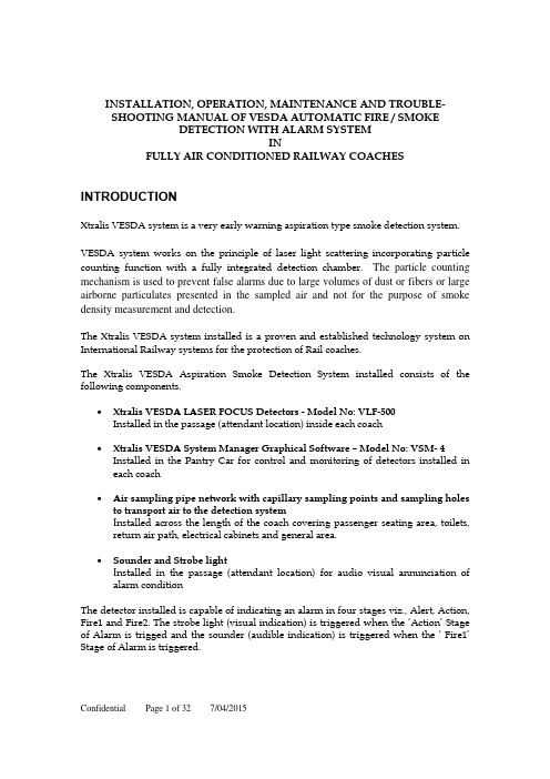
INSTALLATION,OPERATION,MAINTENANCE AND TROUBLE-SHOOTING MANUAL OF VESDA AUTOMATIC FIRE / SMOKEDETECTION WITH ALARM SYSTEMINFULLY AIR CONDITIONED RAILWAY COACHES INTRODUCTIONXtralis VESDA system is a very early warning aspiration type smoke detection system. VESDA system works on the principle of laser light scattering incorporating particle counting function with a fully integrated detection chamber.The particle counting mechanism is used to prevent false alarms due to large volumes of dust or fibers or large airborne particulates presented in the sampled air and not for the purpose of smoke density measurement and detection.The Xtralis VESDA system installed is a proven and established technology system on International Railway systems for the protection of Rail coaches.The Xtralis VESDA Aspiration Smoke Detection System installed consists of the following components.∙Xtralis VESDA LASER FOCUS Detectors-Model No: VLF-500Installed in the passage(attendant location)inside each coach∙Xtralis VESDA System Manager Graphical Software–Model No: VSM-4 Installed in the Pantry Car for control and monitoring of detectors installed in each coach∙Air sampling pipe network with capillary sampling points and sampling holes to transport air to the detection systemI nstalled across the length of the coach covering passenger seating area, toilets,return air path, electrical cabinets and general area.∙Sounder and Strobe lightI nstalled in the passage (attendant location) for audio visual annunciation ofalarm conditionThe detector installed is capable of indicating an alarm in four stages viz., Alert, Action, Fire1 and Fire2. The strobe light(visual indication) is triggered when the ‘Action’ Stage of Alarm is trigged and the sounder (audible indication) is triggered when the ‘ Fire1’Stage of Alarm is triggered.1X TRALIS VESDA D ETECTOR O PERATIONThe diagram below illustrates the different parts of an Air Sampling Smoke Detection System1.Air is sampled by the Xtralis VESDA detector through a pipe network speciallydesigned to the requirements of the individual train coaches.2.The air sample is filtered by the Xtralis VESDA detector to remove dust and dirtbefore it is passed through the laser detection chamber.The filter used for filtering the air borne dust particles is indicated in the below diagram.HighefficiencyFilterchamber Dust FilterFirst stage of the filter removes dust and dirt from the air sample before the sample enters the laser detection chamber for smoke detection. The second (ultra fine) stage provides an additional clean air supply to keep the detector’s optical surfaces free from contamination, ensuring stable calibration and longer detector life. The detector constantly monitors the filter efficiency and a fault is raised automatically on the detector when the filter needs to be replaced.3.The air sample after filtration enters the laser detection chamber. The laserdetection chamber used for smoke measurement and detection is indicated in the below diagramWhen smoke is present,the laser light gets scattered within the detection chamber that is detected by a very sensitive receiver system using sophisticated electronics. This signal is processed to represent the absolute level of smoke present. When the smoke density reaches the set threshold an alarm is raised.4.The sampled air is expelled via an exhaust port at the top of the detector.The Xtralis VESDA detector components are housed inside a polycarbonate enclosure positioned on a standard mounting bracket supplied with the detector. The detector receives power and communicates with the host equipment via screw terminal connections within the unit. Alarms and troubles are communicated to the host equipment via programmable relays and via an RS232 asynchronous communications port. The front of the detector includes a sophisticated user interface to display the operating state, alarm and fault status of the detector.2X TRALIS VESDA L ASER FOCUS(VLF)D ETECTOREach detector covers an area of up to 500m2for open space protection and maximum pipe length of 50 meters.Instant Recognition display and Instant Fault Finder TM on detector–allows easy determination of detector status and alarm and fault detail3M ONITORING AND C ONTROL S YSTEMTo set up a centralised monitoring system, a VESDAnet loop(RS485)is created by networking all the Xtralis VESDA Detectors installed in each coach in peer to peer/daisy chain.The following block diagram indicates the system setup.This VESDAnet loop is used for PC based monitoring and control using VSM-4 software.V E S D A S y s t e m M a n a g e r-4G r a p h i c S o f t w a r e B a s e d C e n t r a l M o n i t o r i n gThe VESDAnet loop is interfaced using High Level Interface (HLI) with a PC installed at the monitoring location. VESDA System Manager-4 (VSM-4) software is installed on the PC for complete monitoring and control of all the VESDA detectors installed.Key features of VSM-4 software are as follows:∙3-D Floor Plan: showing the entire area and the location of each detector within the area∙Real-time Smoke Trending: Click on a detector and see the real time smoke level in the area. You could also see alarm settings, filter status, event log etc.∙Group Trend Graphs: The Operator could compare the smoke level in multiple areas on real time basis in a single graph. This feature is particularly useful, when the operators monitoring finds all of a sudden smoke level rising in a particular coach, then they could compare the smoke level of this coach with the adjacent coach or farthest coach. The supervisor could also review history of the event across multiple detectors on the same graph to ascertain extent and trends of smoke movement.∙Text2Speech Option: provides an audible warning to operators.∙Status Bar: highlights the latest and most important event (prioritised and colour coded)∙Graphical Location information: exact event location is pinpointed on the floor plan.∙Remote Event Log Retrieval, Viewing and Sorting∙Multiple Event Log Database Management∙Auto-discovery of detector network: wiring order and device configurations.∙Full Remote Programming of all the detectors: change any function or parameter through multiple editing views.∙Event Response notification by Email and SMS to defined users on defined events using SMS module4P IPE N ETWORK L AYOUT AND S AMPLING M ETHODSThe following diagram indicates the typical pipe layout in each coach.The typical arrangement of a concealed sampling point is shown in the diagram below.These sampling points are installed at locations with public (passengers) access–passage and seating area.Inside equipment cabinet,normal sampling holes are considered.In certain locations of the train, Heat Activated Sampling Point (HASP) is used. These areas include engine room of the Power Car,Kitchen Area of Pantry Car and in all Lavotories of all the coaches.The picture below is a sample of HASP sampling head.The HASP head operates on thermal detectors principle in its normal operating mode. As fire starts and develops, heat (ambient temperature) increases to such point that the sampling hole is opened and it becomes a normal air sampling hole, hence the detection of the fire and alarm from Xtralis VESDA detectors. As per the Certificate of Appraisal, issued by National Building Technology Centre of Australian Government, the heat activation temperature is 68 C.DETECTOR INSTALLATION&OPERATIOND ETECTOR MOUNTINGThe VESDA Laser FOCUS can be installed upright, inverted or horizontally.Note:Ensure the smoke detector is mounted away from obstructions and below ceiling LevelCaution:An exhaust deflector must be fitted for upright mounting, unless the exhaust port is connected to a return air pipe.Caution:Do not install this unit on its side. There is a risk of particulate and condensation collecting on critical elements of the detector chamber reducing the detectors performance.Ensure that there is sufficient clearance to mount the detector, noting the location of air sampling pipes and cable entry points.Owing to the rigid nature of the plastic pipe, installation must provide for sufficient movement in all pipework (air inlet, air exhaust and cable pipes) to allow pipe ends to be easily fitted and removed.Mounting locationInstalling the smoke detectorIn all installation cases the mounting bracket must be fitted (upright) as shown in figure.Note:Ensure the mounting surface is flat. This will permit an air tight seal to be achieved between the sampling pipe and the tapered air ports on the detector. Warning:Prior to drilling the attachment holes for the mounting bracket, ensure that all mounting surfaces (i.e. walls, cabinet sides, etc.). are clear of electrical wiring and plumbing.When the pipe network and cabling are already fitted, the bracket can be used to aid alignment of the detector with the pipes. The Installation procedure below explains this process.Installation procedureCut the air inlet pipe and exhaust pipe (if used) at 90 deg., and to the same length (for normal and inverted mounting). Remove all rough edges. This is critical to obtain an air tight seal with the smoke detector.1. Position the air inlet centerline mark (A), see Figure, of the mounting bracket against the end of the air inlet pipe.2. In the cut out section of the mounting bracket mark a line across the top of the cut out if metric size pipe is used or mark a line across the bottom of the cut out if Imperial size pipe is used.3. Slide the mounting bracket down (up for inverted mounting) until the top of the bracket aligns with the marked line.4. Mark off and drill the 2 bracket mounting holes (H).5. Screw the bracket to the mounting surface.6. Hook the smoke detector onto the mounting bracket tabs and pull it down into place.7. Use the two M4 x 20 mm locking screws provided and screw them into the screw holes on the left and right side of the detector. See the items marked (F) in the Figure Detector removal.8. The air sampling pipe can now be attached and power connected.(See section wiring connections for connection information).Mounting bracket orientation for upright mountingMounting Bracket Rear ViewAir inlet pipe connectionsThe tapered shape of the air inlet port is designed to accept standard pipes of OD 25 mm (ID 21 mm) or IPS¾ in (OD 1.05 in) and provide an air tight seal.Note:Do not glue the air inlet pipe to the detector. This will void your warranty.Detector cabling requirementsThe screw type terminals located on the termination card within the VESDA Laser FOCUS will accept wire sizes from 0.2sq. mm to 2.5sq. mm(30–12 AWG).To reach the terminal block, open the field service access door,(see Controls and indicators section), and then unscrew the front cover retaining screws. Lift off and swingdown the front cover. The terminal block is located on the right hand side of the detector.Terminal blockGPI–General Purpose Input (Terminals 1 & 2)The General Purpose Input (GPI) is a programmable input. When the GPI function parameter is set to external,the detector shall indicate an external equipment fault condition by monitoring the line impedance. An End of Line (EOL) resistor is supplied with the product and must be assembled in parallel with the device to be monitored. The EOL resistor provides a known termination to the external equipment, this allows the VLF to detect open or short circuits. The detector monitors the EOL resistor, see Figure, and reports any faults when the GPI function is set to any value, except None.Caution:These terminal blocks come assembled and should NOT be disassembled.If GPI will not be used we recommend that you leave the EOL resistor assembled.Power supply (Terminals 8, 9, 10 & 11)It is recommended that the power supply be compliant with local codes and standards required by the regional authority.Caution:Check the product termination wiring label during installation and subsequent Maintenance visits.Operating voltage: 24 VDC nominal (18-30 VDC)Power consumption: 5.2 W nominal, 7.0 W in alarmCurrent consumption: 220 mA nominal, 295 mA in alarmRelays (Terminals 12-20)The relays allow alarm and fault signals to be hard wired to external devices, such as fire alarm control panels and loop interface modules away from the detector (example, sounding a siren at Action threshold).Note:By default, the Fault relay is normally energized when no fault is present. For example when there is no fault present, terminal 12 is held open and terminal 14 is held closed. When there is a fault present, terminal 12 is held closed and terminal14 is held open.Interface cardThe VESDA LaserFOCUS allows for the installation of network interface card used for networking multiple detectors to form a VESDAnet.Network CardInstalling the VESDAnet Card into VLFCaution:The detector must be powered down before installing or swapping an interface card otherwise damage may occur.Detector with front cover open showing the space for interface card inside thedetector1.Ensure the detector is powered off.2.Open the VLF. See the VLF product guide for details.3.Plug the interface cable from the VESDAnet Interface Card into the socketmarked (A).4.Place the card in the space provided, ensuring that the mount for the screwmatches up with the hole on the card. The interface cable should fold under thecard.5.Once the card is seated firmly, use the screw provided to secure the card.Themounting screw must be installed as it also grounds the card.6.Power up the detectorDetector with front cover open with interface card installed inside the detectorTesting the Installed VESDAnet Interface CardThe VESDAnet Interface Card uses LEDs to signify certain conditionsTo test the card:1.Apply power to the VLF.2.View green Power LED and flashing SYS OK LED on the card.3.View amber DET LED lit.4.View amber LEDs lit corresponding to correct Port A and B connections to thenext device.Typical Wiring to VESDAnet–Network of detectors installed in different coachesRS232 Compatible serial portThe RS232 serial port requires a standard 9-pin DB9 PC COM serial extension cable (male to female) for configuring the detector using a PC with VESDA System Configurator (VSC)installed, for status monitoring and command input, and for event log extraction and software upgrades.9 Pin connector and RS232 serial portInstallation ChecklistPerform the following checks listed below to ensure that all the necessary items are completedInstallation ChecklistC OMMISSIONING SMOKE TESTIt is recommended that a smoke test be carried out to prove the integrity of the pipe network, to demonstrate that the system is working and to measure the transport time to the detector.This test involves introducing a smoke sample at the furthest sampling hole and then measuring the time taken for the smoke to travel to the detector. Results are logged and compared to subsequent tests to note variations of the system.P RODUCT I NTERFACEThe VESDA LaserFOCUS provides the following information and control options without the need for additional configuration tools.• Detector status: Normal, Alarm, Disabled and Fault.• Alarm levels: Alert, Action, Fire 1 and Fire 2.• Smoke levels relative to Fire 1.• Detector fault types (Instant Fault Finder).• Test, Reset and Disable.• AutoLearn Smoke (setting alarm thresholds).• AutoLearn Flow (setting baseline for normalizing air flow and flow thresholds).Instant Recognition DisplayThe Instant Recognition display provides you with an immediate understanding of smoke levels relative to Fire 1 alarm threshold.Detector control buttonsSmoke level displayThe smoke level is displayed on the Smoke Dial and provides incident information essential for effective response in very early warning situations. This display provides you with an instant understanding of the smoke event relative to the Fire 1 Alarm Threshold. Between 1 and 10segments may illuminate. Each segment is equivalent to 1/10 of a Fire 1 warning.Smoke level and fault condition displayDETECTOR SPECIFICATIONPower Supply-Supply Voltage 24 VDC nominal (18-30 VDC) Power Consumption @ 24 VDC- 5.2 W nominal, 7.0 W in alarmCurrent Consumption @ 24 VDC-220 mA nominal, 295 mA in alarmCase Dimensions (WHD)-245 mm x 175 mm x 90 mm(95/8 in. x 6 7/8 in. x 31/2 in.)Weight- 2 kg (approx. 4.4 lbs)IP Rating-IP30Mounting-Upright, inverted or horizontal with appropriatemounting bracketOperating ConditionsDetector Ambient0o C to 40o C (32o F to 104o F)Sampled Air0o C to 40o C (32o F to 104o F)Humidity (non-condensing)5% to 95%Sampling NetworkAir inlet pipe(PVC pipe)OD 25 mm (ID 21 mm) / IPS ¾ in. (OD 1.05 in.) Single pipe length50 m max.Branch pipe length30m (50 ft.) max. per branchArea Covered-Upto500 m2Field WiringAccess 3 x 25 mm (1 in.) Cable entries (1 rear entry) Terminals0.2 mm2-2.5 mm2 (30-12 AWG)Interfaces Power In/Out.Fire 1 Relay(changeover, 2A @ 30 VDC).Action Relay(changeover, 2A @ 30 VDC).Fault Relay(changeover, 2A @ 30 VDC).General Purpose Input(clean contact).External display port(with power limited output).RS232 programming port.Alarm RangesAlert, Action0.025–2.0% obs/m (0.008–0.625% obs/ft.)*Fire 1, Fire 20.025–20% obs/m (0.008–6.25% obs/ft.)* Individual Delays0-60 seconds2 Threshold sets (1 & 2)Day and nightDisplay4 Alarm State Indicators(Alert, Action, Fire 1 and Fire 2).Fault and Disabled Indicators.10-sector Smoke Level Indicators.VESDA®LaserFOCUS VLF-250 Product Guide3710-sector Instant Fault Finder.Reset, Disable and Test Controls.Smoke and Flow AutoLearn Controls and Indicators.Event LogUp to 18 000 events stored.Smoke trend, flow trend, faults events, configuration events and operational events.Date and time stamp.AutoLearn Smoke & FlowMinimum 15 minutes, maximum 15 days (default 14 days). During AutoLearn, thresholds are NOT changed from pre-set values.TROUBLESHOOTINGInstant Fault FinderWhen a fault is registered on the detector, the fault light remains ON for Major Fault situations and flashes for Minor Fault.The Instant Fault Finder function is operated by pressing the Reset and Disable buttons together.Instant Fault Finder provides rapid fault diagnosis and is an additional function of the Smoke Dial display. One or more segments of the Smoke Dial will illuminate, indicating the fault by number.The Instant Fault Finder function aids rapid diagnosis of faults.Instant fault finder diagnosisMAINTENANCEThe VESDA LaserFOCUS smoke detector continuously monitors its own operation and conducts frequent health checks. There are two serviceable items, the air filter cartridge and the aspirator.Caution:Electrostatic discharge precautions need to be taken prior to removing the front cover from the detector otherwise damage may occur to the detector.Maintenance-replaceable itemsPrior to any work or maintenance being carried out on the VESDA LaserFOCUStake the necessary steps to advise the monitoring authority that power may be removed and the system disabled.Maintenance scheduleMaintenance should be conducted by a qualified service contractor.Maintenance scheduleReplace the Filter Cartridge (VLF)The VESDA Laser FOCUS smoke detector uses a disposable dual stage air filter cartridge. This filter removes dust contamination from sampled air and provides a clean air bleed to preserve the detector chamber optics. The detector constantly monitors filter efficiency. To maintain the operational integrity of the smoke detector, it is recommended that the filter be replaced every2 years, or when a filter fault occurs or more often for environments that experience high levels of contamination.A fault is raised on the detector, when the filter needs to be replaced. During the replacement process the detector needs to be informed that a new filter has been installed.Note:Ensure the area surrounding the filter is clear of dirt and debris prior to replacement.Note:The filter is for single use only, it cannot be cleaned and re-used.Filter replacement stepsEnsure the detector remains powered up during filter replacement and a new filter cartridge is available:1. Push in the security tab and lift up the field service access door (A).2. Set the detector to‘Standby’ mode by pressing the Disable button for 6 seconds. The Disabled LED begins to flash. After releasing the Disable button the disabled LED will slowly flash.3. Undo the recessed retaining screw (C) and pull out the old filter (B).4. Using your finger, firmly press the filter switch (D) (in the filter recess of the detector)5 times within 5 seconds to confirm to the detector that a new filter is about to beinstalled (see inset). A LED next to the serial interface will flash each time you push the filter switch, and will continue flashing once you have successfully pressed the switch 5 times in 5 seconds.5. Insert the new filter (VSP-005) and tighten the retaining screw.6. Press the Disable button for 6 seconds to return the detector to normal operation.7. Record the filter replacement date on the filter.8. Close the field service access door.Filter replacementAspirator replacementCaution:Electrostatic discharge precautions need to be taken prior to removing the front cover from the detector otherwise damage may occur to the unit.Aspirator removal (assumes normal mounting, see Figure):1. Disconnect power to the detector.2. Push in the security tab and lift up the field service access door.3. Unscrew the two front cover retaining screws, lift and swing down the front cover.4. Only disconnect the fan wiring loom from the connection point (E) at the aspirator.5. Undo the retaining screw on the aspirator (A).6. Swing out the aspirator, then lift and remove it from the detector.LegendNote:Any time the aspirator is removed ensure the area surrounding the aspirator is clear of dirt and debris prior to replacement.Note:Care must be taken during aspirator replacement. The aspirator must be correctlyseated; this is essential so that gaskets are not damaged or dislodged from the underside of the aspirator.Aspirator replacement steps1. Clip the aspirator (VSP-715) into the retaining clip (D) and swing it back into the detector.2. Tighten the retaining screw (A) (do not over tighten).3. Reconnect the fan loom to the aspirator (E).4. Replace the front cover and screw it into place.5. Close the field service access door.6. Reconnect power to the detector.Aspirator replacementCleaning Sampling PipesFollow the instructions below to clean the sample pipe network.1.Ensure that detectors are isolated from the monitoring panel and fire suppressionsystems.2.Notify the relevant authorities that the work is being performed.3.Check and record the current airflow for before and after comparison.4.Disconnect the detector power supply.5.Remove all pipes from the detector inlet(s) and exhausts then cover them toensure that no further dust can enter the detector.6.Ensure that end caps are set firmly in place.7.Connect a vacuum cleaner to the detector end of each pipe in turn. When turnedon, it will extract dust and contaminants that have built up inside the pipes. 8.Alternatively, introduce compressed air (400 KPa for 2 minutes) at the detectorend of each pipe in turn to blow dust and contaminants out through the sample holes.9.Take precautions to ensure that dust is not blown into undesired areas. Ensurethat end caps are still set firmly in place.pare the before and after flow rates. Ideally, the flow should be close to100% for each used pipe. If this is not the case, the capillaries and detector may need closer inspection. If the sample pipe network appears to be OK, continue with the remainder of this section to determine the cause of the reduced airflow.11.Once the system has been serviced, cleaned, tested and is operating fault-free,return it to its normal operating mode.。
系统维护方案
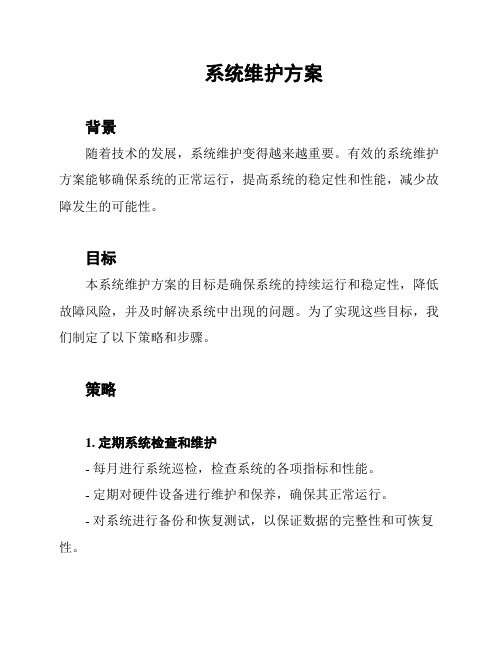
系统维护方案背景随着技术的发展,系统维护变得越来越重要。
有效的系统维护方案能够确保系统的正常运行,提高系统的稳定性和性能,减少故障发生的可能性。
目标本系统维护方案的目标是确保系统的持续运行和稳定性,降低故障风险,并及时解决系统中出现的问题。
为了实现这些目标,我们制定了以下策略和步骤。
策略1. 定期系统检查和维护- 每月进行系统巡检,检查系统的各项指标和性能。
- 定期对硬件设备进行维护和保养,确保其正常运行。
- 对系统进行备份和恢复测试,以保证数据的完整性和可恢复性。
2. 及时更新和升级- 及时安装系统和应用程序的软件更新,包括安全补丁和功能改进。
- 定期进行系统和应用程序的版本升级,以提高系统的性能和安全性。
3. 监控和预警- 配置系统监控工具,实时监测关键指标和性能。
- 设定预警机制,及时发现并解决潜在的问题。
4. 故障处理和问题解决- 当系统出现故障或问题时,及时响应并进行排查和修复。
- 建立故障处理流程和问题解决方案,确保问题能够得到有效解决。
5. 定期培训和知识分享- 为系统维护人员提供定期培训和知识分享机会,提升其技术水平和维护能力。
- 建立知识库,记录和分享经验和教训,以便于今后的系统维护工作。
步骤1. 建立系统维护团队,明确各成员的职责和权限。
2. 制定系统维护计划,包括巡检时间表、更新和升级计划等。
3. 配置系统监控工具,确保能够实时监测系统的性能和指标。
4. 定期进行系统巡检,记录巡检结果并及时处理异常情况。
5. 根据巡检结果进行故障排查和修复,确保系统的稳定运行。
6. 按计划进行软件更新和升级,确保系统的安全性和性能。
7. 建立问题解决流程,确保故障能够及时得到解决。
8. 定期组织培训和知识分享活动,提升团队的维护能力和问题解决能力。
结论本系统维护方案旨在确保系统的持续运行和稳定性,并及时解决系统中出现的问题。
通过定期检查、及时更新和升级、监控预警、故障处理和培训知识分享等策略和步骤,我们能够有效地维护系统,并提高其稳定性和性能。
持续性驱动系统维护与保养指南

持续性驱动系统维护与保养指南随着科技的不断进步,持续性驱动系统在各个行业中得到了广泛应用。
无论是工业生产中的机械设备,还是家用电器中的电动机,都离不开持续性驱动系统的支持。
然而,由于使用频繁和长时间运行,这些系统也容易出现故障和损坏。
因此,维护和保养持续性驱动系统显得尤为重要。
首先,定期清洁是持续性驱动系统维护的基础。
由于系统长时间运行,会吸入大量的灰尘和杂质,如果不及时清理,会导致系统散热不良,影响系统的正常运行。
因此,定期清洁系统的外壳和内部零部件是必要的。
可以使用吸尘器或软刷进行清洁,注意不要用水直接冲洗,以免损坏电路板和电子元件。
其次,定期检查和更换润滑油是保养持续性驱动系统的重要环节。
润滑油在系统运行中起到润滑和冷却的作用,但长时间使用后会变质和污染,影响系统的正常运行。
因此,定期检查润滑油的质量和量,并及时更换,可以有效延长系统的使用寿命。
同时,要根据系统的使用频率和工作环境,选择合适的润滑油种类和规格。
另外,定期检查电源和电线连接是保证持续性驱动系统安全运行的重要措施。
电源是系统正常运行的基础,而电线连接的稳固性直接影响系统的工作效果和安全性。
因此,定期检查电源插头和电线连接是否松动或损坏,及时修复或更换。
同时,还要注意电源的稳定性和电压的波动,避免因电压不稳造成系统的故障或损坏。
此外,定期进行系统的故障诊断和维修是保养持续性驱动系统的重要手段。
随着系统的使用时间的增加,零部件的老化和磨损是不可避免的。
因此,定期进行系统的故障诊断,及时发现和修复故障,可以有效避免故障的扩大和损坏的加重。
在维修过程中,要注意使用合适的工具和方法,避免对系统造成二次损坏。
最后,持续性驱动系统的保养还需要注重系统的环境和工作条件。
例如,系统在高温环境下工作时,要保证散热良好,避免过热引起系统的故障。
在潮湿环境中工作时,要防止水分进入系统内部,导致短路和损坏。
此外,还要注意防雷和防静电措施,避免因外部干扰而引起系统的故障。
- 1、下载文档前请自行甄别文档内容的完整性,平台不提供额外的编辑、内容补充、找答案等附加服务。
- 2、"仅部分预览"的文档,不可在线预览部分如存在完整性等问题,可反馈申请退款(可完整预览的文档不适用该条件!)。
- 3、如文档侵犯您的权益,请联系客服反馈,我们会尽快为您处理(人工客服工作时间:9:00-18:30)。
在缺省设置中,该按钮不起作用。要想启 用此按钮,需使用 Xtralis VESDA 系统配 置软件 (Xtralis VSC)。
注意 : 在测试开始之前,须通知监测部 门。
要启用此按钮,需要按下和松开 Fire 1 (火警 1)测试按钮。这样就可以激活烟 雾指示刻度盘上的各个部分以及直至火警 1 的报警条件 (在所设置的延时后)。再 次按下 Fire 1 (火警 1)测试按钮以便停 止测试,并解除所有锁定的报警。
Xtralis VESDA
6 探测器概览
Xtralis VESDA VLF-250 产品指南
特性
• 绝对烟雾值的激光探测 • 极宽的灵敏度范围 • 可编程报警阈值 • 二级空气过滤器 • 即时识别显示器 • Instant Fault FinderTM (即时故障探测) • AutoLearnTM Smoke (烟雾自学习) • AutoLearnTM Flow (气流自学习) • 超声波气流传感 • 参考探测器 (需要配备 VESDAnet 接口卡) • 现场维护检修门 • 独立事件记录 • 支持采样管网模型软件 - ASPIRE2TM • 用于现场的 Xtralis VESDA 系统配置软件 (Xtralis VSC)
表示已达到 “ 火警 2” 阈值 表示已达到 “ 火警 1” 阈值 表示已达到 “ 行动 ” 阈值 表示已达到 “ 警告 ” 阈值 表示设备已经停用 (持续)或处于待机模式 (闪烁) 在探测器通电时发光 故障灯持续发光表示紧急故障 (UF)。闪烁表示非紧急故障 (NUF)
LED 指示灯 颜色 红色 红色 红色 红色 黄色 绿色 黄色
图 23 - VLF 探测器前视图
24
/china
Xtralis VESDA
即时识别显示器
Xtralis VESDA VLF-250 产品指南
即时识别显示器可以使用户即时了解烟雾浓度 (相对于 “ 火警 1” 报警阈值)的情况。
A B
C
D
G
E
F
图注
选项
定义
A FIRE 2 (火警 2) B FIRE 1 (火警 1) C ACTION (行动) D ALERT (警告) E DISABLED (停用) F POWER (电源) G FAULT (故障)
利用即时故障探测器对 VLF 探测器进行故障诊断
即时故障探测器功能有助于故障的快速诊断。
故障 1 2 3
4 5 6 7
类型 过滤器故障 吸气泵故障
高气流故障
低气流故障 未使用 外部设备 / 供 电电源故障 接口卡故障
解释 如果因为灰尘或烟雾污染,或 者达到了寿命期限,就应当更 换空气过滤器。
吸气泵发生故障
即时故障探测器
当探测器上的一个故障被确认之后,如果是紧急故障 (UF),故障指示灯 (D)会持续发光,如 果是非紧急故障 (NUF),故障指示灯会闪烁。
同时按下复位和停用按钮,即时故障探测功能就会启动。即时故障探测功能可以提供快速故障诊 断,它是烟雾浓度指示刻度盘的一个附加功能。 烟雾浓度指示刻度盘上的一个或多个部分会发 光,以数字形式显示故障。下表提供了详细故障信息和操作建议。
B
C A
D
图注
A 烟雾浓度指示刻度盘及故障类型显示 C Disable (停用)按钮 器
B Reset (复位)按钮
D Fault (故障)按钮
图 27 - 烟雾浓度及故障情况显示器
/china
29
Xtralis VESDA VLF-250 产品指南
Xtralis VESDA
启动后使火警继电 器输出停用并报告 故障 按住 Disable (停 用)按钮 6 秒钟就 会使探测器进入待 机状态。
说明
按住此按钮可测试设备上 LED 指示灯的功 能。
要想启用或锁定此按钮,需要使用 Xtralis VESDA 系统配置软件 (Xtralis VSC)软件。
松开此按钮可以解除锁定的故障和报警。 这时报警灯和故障灯将会灭掉。如果系统 仍处于报警或故障模式,在适当的延时后 这些灯会重新发光。
即时故障探 测器
指示探测器当前出 现的故障
同时按住复位按钮和停用按钮后,可在烟 雾指示刻度盘上以数字形式显示故障类 型。
见第 26 页上 “ 利用即时故障探测器对 VLF 探测器进行故障诊断 ” 中的故障定 义。
Fire 1 (火警 1) 测试
Hale Waihona Puke 模拟 Fire 1 (火警 1) 条件,在适当的延 迟后报警继电器会 被激活。
AutoLearn Flow (气流 自学习)
探测器可以自动测 量进入采样管的气 流并设置气流阈值
见 17 页上 “AutoLearn Flow (气流自学 习)”。
按下凹形的 AutoLearn Flow (气流自学 习)按钮即可对气流故障阈值进行设置, 并对探测器的进行气流标定。在自学习过 程 (持续 14 天,这也是缺省周期)中, 按钮旁边的 LED 指示灯会持续发光。要想 启用这一功能,可以再次按下 AutoLearn Flow (气流自学习)按钮。
该按钮可以让操作员在停用模式和常规模 式之间切换。在停用后,不再向系统报告 烟雾和气流 (例如,FACP 火灾报警控制 器)。
要想启用或锁定此按钮,需要使用 Xtralis VESDA 系统配置软件 (Xtralis VSC)软件。
VLF 探测器停用后吸气泵的风扇将继续转 动,但在待机状态下会停止运转。
应用
可以使用 VLF 探测器为开放区域、回风格栅或为机柜等众多小型区域提供保护,包括:
• 通讯设施 • 计算机室 • 控制室 • 存储设备 • 电气柜和开关柜
如需规范要求的详细信息,见页码 V 上 “ 空气采样烟雾探测的规范和标准 ”。
/china
23
Xtralis VESDA VLF-250 产品指南
流自学习功能) G 控制按钮定义 H 保险舌
图 26 - VLF 探测器,现场维护检修门打开
/china
27
Xtralis VESDA VLF-250 产品指南
探测器控制按钮
Xtralis VESDA
图标
按钮 复位
Disable (停用)
用途
使系统复位并重新 正常运行
注意 : 请记住要在测试结束后使系统回 复正常模式。
28
/china
Xtralis VESDA
Xtralis VESDA VLF-250 产品指南
AutoLearn Smoke (烟 雾自学习)
Automatically (烟雾自学习)可 以在常规工作环境 的基础上自动设置 报警阈值
注意 :
图 24 - 即时识别显示器
我们提供了两套即时识别显示器图标,在本手册中经常出现。用户无需阅读图标旁 的英文说明就能够通过国际通用图标对故障进行确认。
/china
25
Xtralis VESDA VLF-250 产品指南
Xtralis VESDA
控制按钮和指示灯
用户界面信息和控制按钮
用户界面信息和控制按钮位于现场维护检修门盖的后面。
Xtralis VESDA VLF-250 产品指南
A
B
E C
F
D
G
H
图注
A 即时故障探测器故障说明 B 二级空气过滤器 C 警报级别定义 D 控制按钮-复位、停用、(即时故障探测)和测试 E RS232 DB9F 串口 F 控制按钮 - AutoLearn Smoke (烟雾自学习), AutoLearn Flow (气
打开现场维护检修门后可以找到控制按钮。 用平头螺丝刀按下位于探测器右侧的保险舌,检修门 就会打开,然后利用检修门两侧的卡头抬起检修门 (见下图)。
A
图注
C
A 保险舌
B 卡头
C 现场维护检修门
B 图 25 - 现场维护检修门的保险舌和卡头
26
/china
Xtralis VESDA
介绍
VLF 烟雾探测器的即时识别显示器可以显示警报级别和探测器状态等信息。 作为即时识别显示器 的一部分,烟雾指示刻度盘 (见 19 页上 “VLF 探测器前视图 ”, 中的 (F),第 3 页上 “ 空气 采样烟雾探测的规范和标准 ”)可以提供烟雾事件的明确信息(相对于 “ 火警 1” 报警阈值)。 在使用即时故障探测功能时,该显示器还能够标识出系统和运行故障。 烟雾指示刻度盘上的各部 分都对应着一个特殊的故障状况。
7 产品界面
在无需额外配置工具的情况下, VLF 探测器可以提供下列信息和控制选项:
• 探测器状态:正常、报警、停用和故障; • 警报级别:“ 警告 ”、“ 行动 ”、“ 火警 1” 和 “ 火警 2” ; • 对应 “ 火警 1” 的烟雾浓度; • 探测器故障类型 (即时故障探测) • 测试、复位和停用; • AutoLearn Smoke (烟雾自学习) (设置警报阈值) • AutoLearn Flow (气流自学习) (为标准气流和气流阈值设定基准)
探测器上有一个现场维护检修门,这样就在探测器调试的过程中方便地访问 AutoLearn (自学 习)功能。 提供它,可以更换过滤器,还可以连接电脑以便进行全面的设置和诊断。
探测器使用超声波气流传感,通过对采样管中气流变化的探测,监视采样管网的完整性。 超声波 气流传感不受温度、湿度和压力的影响。
探测器中的历史事件是由非易失性独立事件记录功能提供的。包括烟雾趋势数据、气流趋势数 据、故障事件、配置事件和运行事件等。使用 VSC 软件就可以对这些事件类型分别进行过滤。
表 6 - 探测器按钮
烟雾浓度和即时故障探测的显示器
在正常运行条件下,环状烟雾浓度指示刻度盘可以显示出采样空气中的烟雾浓度。通过即时故障 探测器,烟雾浓度指示刻度盘可以暂时将各段转化为故障指示灯,其中每段都对应一个特定的故 障情况。