毕业论文外文翻译-浅谈差速器
汽车差速器中英文对照外文翻译文献
汽车差速器中英文对照外文翻译文献 FailureanalysisofanautomobiledifferentialpinionshaftAbstractDifferentialisusedtodecreasethespeedandtoprovidemomentincreasefortransmittingthecomingfromtheenginetothewheelsbyturning itaccording tothesuitable angleinvehicles andtoprovide thatinnerandouterturndifferently. Piniongearandshaftattheentrancearemanufactured asasinglepartwhereastheyareindifferentformsaccordingtoautomobileMirrorgearwhichwillworkwiththisgearshouldbecomefamiliar beforetheassembly. Incaseofanybreakdown, theyshouldbechangedasapair.Generally, inthesesystemsthereareweardamagesingears.Thegearinspected inthisstudyhasdamageasaformofshaftfracture.Inthisstudy,failureanalysisofthedifferentialpinionshaftiscarriedout.Mechanicalcharacteristics ofthematerialareobtainedfirst.Then,themicrostructure andchemicalcompositionsaredetermined.Somefractographicstudiesare2020ElsevierLtd.Allrightsreserved.Keywords: Differential;Fracture;Powertransfer;Pinionshaft1.IntroductionThefinal-drivegearsbedirectlyorindirectly drivenfromtheoutputgearingofthegearbox.Directlydrivenfinaldrivesareusedwhentheengineandtransmission unitscombinedtogethertoformanintegralconstruction. Indirectlydrivenfinaldrivesareusedattherearofthevehiclebeingeithersprungandattachedthebodystructureorunsprungandincorporated intherear-axlecasing.Thefinal-drive gearsareusedinthetransmission systemforthefollowingreasons[1]:(a)toredirectthedrivefromthegearboxorpropeller shaftthrough90°and,(b) toprovideapermanent gearreduction betweentheengineandtheroad-wheels. Invehicles,differential isthemainpartwhichtransmitsthemovementcomingfromtheenginetothewheelsOnasmoothroad,thecomes tobothwheels evenly. Theinner wheel should turnlessandtheouter wheel should turnmoretodotheturning without lateralslippingandbeingflung.Differential, whichisgenerallyplacedinthemiddlepartoftherearbridge,consistsofpiniongear,mirrorgear,differential box,twoaxlegearandtwopinionspidergears.Aschematicillustration ofadifferential isgiveninFig,1.ThetechnicaldrawingofpinionthefracturedshaftisalsogiveninFig,2,Fig.3showsthephotographofthefracturedpinionshaftandthefracturesectionisindicated.In differentials,andpiniongeararemadetogetusedtoeachotherduringmanufacturing andthesameserialnumberisgiven.Bothofthemareoncondition thatthereareanyproblems. Inthesesystems, thecommondamageisthewearofgears[2-4].Inthisstudy,thepinionofthedifferential ofaminibushasbeeninspected. Theminibusisadieselvehicledrivenattherearaxleandhasapassengercapacityof15people.Maximumenginepoweris90/4000HP/rpm,andmaximumtorqueis205/1600Nm/rpm.Itstransmission boxhasmanualsystem(5forward,1back).Thedamagewascausedbystoppingandstartingtheminibusatatrafficlights.Inthisdifferential, entranceshaftwhichcarriesthepiniongearwasbroken. Various studies havebeenmadetodetermine thetypeandpossible reasons ofthedamage. Theseare:?studies carried outtodetermine thematerialoftheshaft;?studiescarriedouttodeterminethemicro-structure; ?studiesrelatedtothefracturesurface.Thereisacloserphotographofthefractured surfacesandfractureareainFig.4.Thefracturewascausedbytakingoutcircularmarkgearseeninthemiddleofsurfaces.2.ExperimentalprocedureSpecimens extractedfromtheshaftweresubjectedtovarioustestsincludinghardnesstestsandmetallographicandscanningelectronmicroscopyaswellasthedeterminationofchemicalcomposition.Alltestswerecarriedoutatroomtemperature.2.1 Chemicalandmetallurgical analysisChemicalanalysisofthefractureddifferentialmaterialwascarriedoutusingaspectrometer. Thechemicalcomposition ofthematerialisgiveninTable1.Chemicalcomposition showsthatthematerialisalowalloycarburizing steeloftheAISI8620type.Hardenability ofthissteelisverylowbecauseoflowcarbonproportion.Therefore,surfaceareabecomeshardandhighlyenduring,andinnerareasbecomestoughbyincreasing carbonproportion onthesurfaceareawithcementation operation. Thisisthekindofsteelwhichisgenerally usedinmechanical partssubjected dotorsionandbending.Highresistance isobtainedonthesurfaceandhighfatigueendurance valuecanbeobtainedwithcompressiveresidual stressbymakingthesurfaceharder[5-7].In whichalloyelements distribute themselves incarbonsteelsdependsprimarily onthecompound andcarbideformingtendencieseachelement. Nickeldissolves intheαferrite ofthesteelsinceithaslesstendency toformcarbides thanironSilicon combines tolimitedextentwiththeoxygenpresentinthesteeltoformnonmetallic inclusions butotherwise dissolves intheferrite.Mostofthemanganese addedcarbonsteelsdissolvesintheferrite.Chromium,whichhasasomewhatstrongercarbide-forming dependsontheiron,partitionsbetweentheferriteandcarbidephases.distributionofchromiumdependsontheamountofcarbonpresentandifotherstrongercarbide-forming elementssuchastitaniumandcolumbiumamountofcarbonpresentandifotherstrongercarbide-forming elementssuchastitaniumandcolumbiumareabsent.Tungstenandmolybdenumcombinewithcarbontoformcarbidesisthereissufficientcarbonpresentandifotherstrongercarbide-forming elementssuchdatitaniumandcolumbiumareabsent.Manganeseandnickellowertheeutectoidtemperature[8].Preliminarystructural examination ofthefaileddifferential materialisshowninFig.5.Itcanbeseenthatthematerialhasamixedstructureinsomeferrite existprobably asaresult ofslowcooling andhighSicontent. HighSicontent inthistypeofsteelimproves thetreatmentsusceptibility aswellasanimprovementofyieldstrengthandmaximumstresswithoutanyreductionofductility[9].Ifthemicro-structure cannotbeinvertedtomartensitebyquenching,areductionoffatiguelimitisobserved.There areareaswithcarbonphaseinFig.5(a).ThereisthetransitionboundaryofinFig.5(b)and(c)showsthematrixregionwithoutcarburization. Asfarasitisseenintherephotographs, thepiecewasfirstthenthequenchingoperationwasdonethantempered.Thissituationcanbeunderstood fromblindmartensite plates.2.2 HardnesstestsThehardnessmeasurements arecarriedoutbyaMetTest-HT typecomputer integrated hardness tester.Theloadis1471N.Themediumhardness valueoftheinterior regionsisobtained asobtainedas43HRC.Microhard-nessmeasurements havebeenmadetodeterminethechanceofhardnessvaluesalongcross-section be-causeofthehardeningofsurfaceduetocarburization. TheresultsofVickershardnessmeasurementunderaloadof4.903NareillustratedinTable2.2.3Inspectionofthefracturedirectobservations ofthepiecewithfracturedsurfacesandSEManalysesaregiveninthischapter.Thecrackstartedbecauseofapossibleproblemthebottomofnotchcausedtheshafttobebrokencompletely. Thecrackstartedontheouterpart,aftersometimeitcontinued beyondcentreandtherewasonlyalittlepartleft.Andthispartwasbrokenstatically duringsuddenstarting ofthevehicleatthetrafficlights.Asacharacteristic ofthefatigue,therearetworegionsinthefracturedsurface.Theseareasmoothsurfacecreatedbycrackpropagation。
机械制造及其自动化专业外文翻译--差速器壳体工艺及工装设计

外文原文Differential shell process and boring tooling design The motor car engine power transmission shaft and the clutch, and finally to drive around again assigned half shaft drive wheels, in this article, the drive power transmission way, it is the final assembly of the main parts is reducer and differential. Gear reducer is increased, the function of torque and completely on gear meshing gears, between are easy to understand. But more difficult to understand differential, what, why "differential differential"?The car is driven car differential main parts. It is in the power of both half shaft transmission shaft, allowing both half with different speed spinning wheels, satisfy both pure rolling form as possible, reducing equi-distant not tire and ground friction.Spider diagramObject graph theory differentialfunctionalAt the turn of the car wheel track line, if the car is circular arc, turn left at the center, and at the same time, the wheels went arc length, the wheels than to balance the difference, left, and right wheel wheels slowlySlip differentialFaster, with different speed up the distance.If you make a whole after wheel, can accomplish on both sides of the wheel speed difference, is also does not have an automatic adjustment. In order to solve this problem, a hundred years ago, France Renault automotive company founderluis Renault will design a differential this thing.Slip differentialconstituteOrdinary differential planetary wheel planetary gear, by plane (d ifferential shell), half axle gear parts etc. The power of the engine into the differential transmissionStructurePlanetary wheel frame, driven directly by the planets wheel driv e, right and left two half shaft, wheel drive left and right. Meet the design requirements of differential (left) and the shaft speed (right) = 2 (axial rotational speed) planet round frame. When the car goe s, left, right wheel and planetary wheel frame of equal speed, and in a state of equilibrium in the balance among car when turning ro und to destruction, reduce the speed, the wheel speed increase.StructurePrincipleThis adjustment is automatic differential here, involves "minimal energyconsumption principle", namely earth all objects are tend to minimum energy. Such a grain of beans in a bowl, beans will automatically stays in the bowl bottom and never stay in the bowl wall, because the bowl bottom is the lowest energy (potential), it automatically select static (minimum) without energy. In the same way,A 3d effectWheel in turning also will be the lowest power consumption tendency, automatically adjusted according to turn radius of the wheel speed around.When turning wheel, because the pull of the phenomenon, the medial wheel slip phenomenon, two driving wheel at will produce two opposite direction of additional force, due to the "principle of minimal energy consumption, will inevitably lead to the wheel speed different sides, thus destroyed the balance between three and half shaft are reflected by the half axle gear planetary gears, forced to produce the half shaft rotation speed, speed, the medial axis speed slow speed, so as to realize the difference on both sides wheels.If the drive wheels on both sides of the drive shaft with a whole rigid connection, only two wheels at the same Angle rotation. So, when the steering wheel, due to the lateral than inside the distance moved across the wheels, will make the scroll wheel on the slide, and drag on the scroll wheel inside the slip. Even the car run straight road gravamen, because although flat tire surface or rolling radius (but ranging from manufacturing error, wear different tyres, ranging from uneven pressure or carrying of sliding wheel) and cause.When the wheel sliding tire wear, not only aggravate increased power and fuel consumption, still can make steering difficulties, braking performance deterio rated. As for the wheels, and does not occur in structure sliding must ensure each wheel at different angles can rotate.Axis between differential driven wheels usually use bearing spindle support in the, can at any Angle rotation, and drive wheels with two and half shaft rigid connection, between two and half shaft with differential. The differential and called shaft between differential.Many of the drive shaft, and to make each off-road vehicle drive to different velocity rotating, in order to eliminate the bridge of the drive wheels, some in two axles sliding between between shaft with differential.Differential inspection1 differential shell doesn't have any properties of crack, shell and planetary gear differential half shaft washer, contact between gear, should be smooth without groove, If there is a slight groove or wear, can continue to use after grinding, or should be replaced or be repaired.2 the planetary gear differential shell and planetary gear wheel when the fitting clearance shall not greater than 0.1-0.15 mm, half axle gear shaft neck and shell hole for clearance, with no obvious loose labels should be replaced or feeling, or repair.Shell's processing technologyThe processing quality not only affects shell, the assembly precision and accuracy, but also affects the movement of the machine working accuracy, performance and life.There are many kinds of shell structure, its size and form with the structure of the machine and the shell in machine has the different function. But they rema in on the analysis from the craft had a lot in common and its structure features are:(1) appearance is basically composed of six or five plane again into the closed-end polyhedron, integral and combined two,(2) structure shape is more complex. Inside the cavity is often, some places "partition wall, shell and uneven thickness thin.(3) shell walls are usually decorate have parallel hole or vertical hole,(4) on the shell, main processing is the number of plane, in addition to many higher accuracy and precision of supporting bearing with less demanding tighten pore.Shell parts technical requirements:(1) bearing support size precision and accuracy, surface roughness, requirements,(2) position precision including hole axis of the distance between the dimension precision, the same axis parallel degree in each hole, and KongDuan facing the coaxial tolerance of vertical axis holes; etc.(3) to meet the needs and positioning of the shell processing machine assembly request, shell and assembly of shell with the datum plane positioning due and certain degree, and the surface roughness requirements, The bearing hole and assembling a certain distance between datum due to the accuracy requirement of the size.中文译文差速器壳体工艺及工装设计汽车发动机的动力经离合器、变速器、传动轴,最后传送到驱动桥再左右分配给半轴驱动车轮,在这条动力传送途径上,驱动桥是最后一个总成,它的主要部件是减速器和差速器。
机械毕业设计英文外文翻译402驱动桥和差速器 (2)

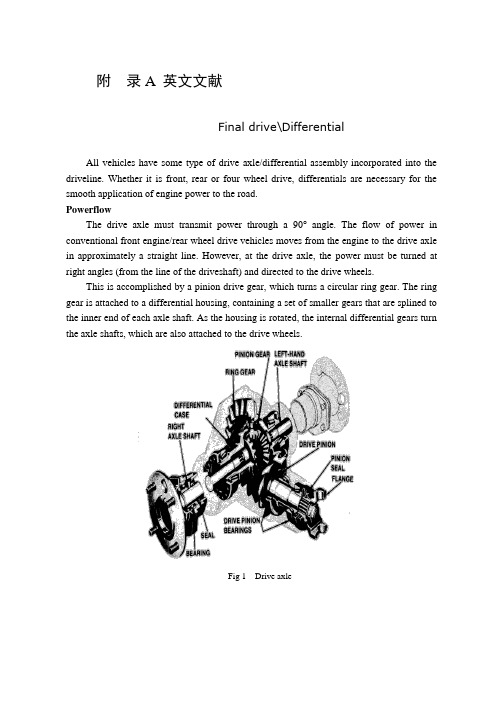
附录附录ADrive axle/differentialAll vehicles have some type of drive axle/differential assembly incorporated into the driveline. Whether it is front, rear or four wheel drive, differentials are necessary for the smooth application of engine power to the road.PowerflowThe drive axle must transmit power through a 90° angle. The flow of power in conventional front engine/rear wheel drive vehicles moves from the engine to the drive axle in approximately a straight line. However, at the drive axle, the power must be turned at right angles (from the line of the driveshaft) and directed to the drive wheels.This is accomplished by a pinion drive gear, which turns a circular ring gear. The ring gear is attached to a differential housing, containing a set of smaller gears that are splined to the inner end of each axle shaft. As the housing is rotated, the internal differential gears turn the axle shafts, which are also attached to the drive wheels.Fig 1 Drive axleRear-wheel driveRear-wheel-drive vehicles are mostly trucks, very large sedans and many sports car and coupe models. The typical rear wheel drive vehicle uses a front mounted engine and transmission assemblies with a driveshaft coupling the transmission to the rear drive axle. Drive in through the layout of the bridge, the bridge drive shaft arranged vertically in the same vertical plane, and not the drive axle shaft, respectively, in their own sub-actuator with a direct connection, but the actuator is located at the front or the back of the adjacent shaftof the two bridges is arranged in series. Vehicle before and after the two ends of the driving force of the drive axle, is the sub-actuator and the transmission through the middle of the bridge. The advantage is not onlya reduction of the number of drive shaft, and raise the driving axle of the common parts of each other, and to simplify the structure, reduces the volume and quality.Fig 2 Rear-wheel-drive axleSome vehicles do not follow this typical example. Such as the older Porsche or Volkswagen vehicles which were rear engine, rear drive. These vehicles use a rear mounted transaxle with halfshafts connected to the drive wheels. Also, some vehicles were produced with a front engine, rear transaxle setup with a driveshaft connecting the engine to the transaxle, and halfshafts linking the transaxle to the drive wheels.Differential operationIn order to remove the wheel around in the kinematics due to the lack of co-ordination about the wheel diameter arising from a different or the same rolling radius of wheel travel required, inter-wheel motor vehicles are equipped with about differential, the latter to ensure that the car driver Bridge on both sides of the wheel when in range with a trip to the characteristics of rotating at different speeds to meet the requirements of the vehicle kinematics.Fig 3 Principle of differentialThe accompanying illustration has been provided to help understand how this occurs.1.The drive pinion, which is turned by the driveshaft, turns the ring gear.2.The ring gear, which is attached to the differential case, turns the case.3.The pinion shaft, located in a bore in the differential case, is at right angles to the axle shafts and turns with the case.4.The differential pinion (drive) gears are mounted on the pinion shaft and rotate with the shaft .5.Differential side gears (driven gears) are meshed with the pinion gears and turn with the differential housing and ring gear as a unit.6.The side gears are splined to the inner ends of the axle shafts and rotate the shafts as the housing turns.7.When both wheels have equal traction, the pinion gears do not rotate on the pinion shaft, since the input force of the pinion gears is divided equally between the two side gears.8.When it is necessary to turn a corner, the differential gearing becomes effective and allows the axle shafts to rotate at different speeds .Open-wheel differential on each general use the same amount of torque. To determine the size of the wheel torque to bear two factors:equipment and friction. In dry conditions, when a lot of friction, the wheel bearing torque by engine size and gear restrictions are hours in the friction (such as driving on ice), is restricted to a maximum torque, so that vehicles will not spin round. So even if the car can produce more torque, but also need to have sufficient traction to transfer torque to the ground. If you increase the throttle after the wheels slip, it will only make the wheels spin faster.Fig 4 Conventional differential Limited-slip and locking differential operationFig 5 Limited-slip differentialDifferential settlement of a car in the uneven road surface and steeringwheel-driven speed at about the different requirements; but is followed by the existence of differential in the side car wheel skid can not be effective when the power transmission, that is, the wheel slip can not produce the driving force, rather than spin the wheel and does not have enough torque. Good non-slip differential settlement of the car wheels skid on the side of the power transmission when the issue, that is, locking differential, so that no longer serve a useful differential right and left sides of the wheel can be the same torque.Limited-slip and locking differential operation can be divided into two major categories:(1) mandatory locking type in ordinary differential locking enforcement agencies to increase, when the side of the wheel skid occurs, the driver can be electric, pneumatic or mechanical means to manipulate the locking body meshing sets of DIP Shell will be with the axle differential lock into one, thus the temporary loss of differential role. Relatively simple structure in this way, but it must be operated by the driver, and good roads to stop locking and restore the role of differential.(2) self-locking differential installed in the oil viscosity or friction clutch coupling, when the side of the wheel skid occurs when both sides of the axle speed difference there, coupling or clutch friction resistance on the automatic, to make certain the other side of the wheel drive torque and the car continued to travel. When there is no speed difference on both sides of the wheel, the frictional resistance disappeared, the role of automatic restoration of differentials. More complicated structure in this way, but do not require drivers to operate. Has been increasingly applied in the car. About non-slip differential, notonly used for the differential between the wheels, but also for all-wheel drive vehicle inter-axle differential/.Gear ratioThe drive axle of a vehicle is said to have a certain axle ratio. This number (usually a whole number and a decimal fraction) is actually a comparison of the number of gear teeth on the ring gear and the pinion gear. For example, a 4.11 rear means that theoretically, there are 4.11 teeth on the ring gear for each tooth on the pinion gear or, put another way, the driveshaft must turn 4.11 times to turn the wheels once. The role of the final drive is to reduce the speed from the drive shaft, thereby increasing the torque. Lord of the reduction ratio reducer, a driving force for car performance and fuel economy have a greater impact. In general, the more reduction ratio the greater the acceleration and climbing ability, and relatively poor fuel economy. However, if it is too large, it can not play the full power of the engine to achieve the proper speed. The main reduction ratio is more Smaller ,the speed is higher, fuel economy is better, but the acceleration and climbing ability will be poor.附录B驱动桥和差速器所有的汽车都装有不同类型的驱动桥和差速器来驱动汽车行驶。
中英文文献翻译-主减速器和差速器
附录A 英文文献Final drive\DifferentialAll vehicles have some type of drive axle/differential assembly incorporated into the driveline. Whether it is front, rear or four wheel drive, differentials are necessary for the smooth application of engine power to the road.PowerflowThe drive axle must transmit power through a 90°angle. The flow of power in conventional front engine/rear wheel drive vehicles moves from the engine to the drive axle in approximately a straight line. However, at the drive axle, the power must be turned at right angles (from the line of the driveshaft) and directed to the drive wheels.This is accomplished by a pinion drive gear,which turns a circular ring gear. The ring gear is attached to a differential housing, containing a set of smaller gears that are splined to the inner end of each axle shaft. As the housing is rotated, the internal differential gears turn the axle shafts, which are also attached to the drive wheels.Fig 1 Drive axleRear-wheel driveRear-wheel-drive vehicles are mostly trucks, very large sedans and many sports car and coupe models. The typical rear wheel drive vehicle uses a front mounted engine and transmission assemblies with a driveshaft coupling the transmission to the rear drive axle. Drive in through the layout of the bridge, the bridge drive shaft arranged vertically in the same vertical plane, and not the drive axle shaft, respectively, in their own sub-actuator with a direct connection, but the actuator is located at the front or the back of the adjacent shaft of the two bridges is arranged in series. Vehicle before and after the two ends of the driving force of the drive axle, is the sub-actuator and the transmission through the middle of the bridge. The advantage is not only a reduction of the number of drive shaft, and raise the driving axle of the common parts of each other, and to simplify the structure, reduces the volume and quality.Fig 2 Rear-wheel-drive axleSome vehicles do not follow this typical example. Such as the older Porsche or Volkswagen vehicles which were rear engine, rear drive. These vehicles use a rear mounted transaxle with halfshafts connected to the drive wheels. Also, some vehicles were produced with a front engine, rear transaxle setup with a driveshaft connecting the engine to the transaxle, and halfshafts linking the transaxle to the drive wheels.Differential operationIn order to remove the wheel around in the kinematics due to the lack of co-ordination about the wheel diameter arising from a different or the same rolling radius of wheel travel required, inter-wheel motor vehicles are equipped with about differential, the latter to ensure that the car driver Bridge on both sides of the wheel when in range with a trip to the characteristics of rotating at different speeds to meet the requirements of the vehicle kinematics.Fig 3 Principle of differentialThe accompanying illustration has been provided to help understand how this occurs.1.The drive pinion, which is turned by the driveshaft, turns the ring gear.2.The ring gear, which is attached to the differential case, turns the case.3.The pinion shaft, located in a bore in the differential case, is at right angles to the axle shafts and turns with the case.4.The differential pinion (drive) gears are mounted on the pinion shaft and rotate with the shaft .5.Differential side gears (driven gears) are meshed with the pinion gears and turn with the differential housing and ring gear as a unit.6.The side gears are splined to the inner ends of the axle shafts and rotate the shafts as the housing turns.7.When both wheels have equal traction, the pinion gears do not rotate on the pinion shaft, since the input force of the pinion gears is divided equally between the two side gears.8.When it is necessary to turn a corner, the differential gearing becomes effective and allows the axle shafts to rotate at different speeds .Open-wheel differential on each general use the same amount of torque. To determine the size of the wheel torque to bear two factors: equipment and friction. In dry conditions, when a lot of friction, the wheel bearing torque by engine size and gear restrictions are hours in the friction (such as driving on ice), is restricted to a maximum torque, so that vehicles will not spin round. So even if the car can produce more torque, but also need to have sufficient traction to transfer torque to the ground. If you increase the throttle after the wheels slip, it will only make the wheels spin faster.Fig 4 Conventional differentialLimited-slip and locking differential operationFig 5 Limited-slip differentialDifferential settlement of a car in the uneven road surface and steering wheel-driven speedat about the different requirements; but is followed by the existence of differential in the side car wheel skid can not be effective when the power transmission, that is, the wheel slip can not produce the driving force, rather than spin the wheel and does not have enough torque. Good non-slip differential settlement of the car wheels skid on the side of the power transmission when the issue, that is, locking differential, so that no longer serve a useful differential right and left sides of the wheel can be the same torque.Limited-slip and locking differential operation can be divided into two major categories:(1) mandatory locking type in ordinary differential locking enforcement agencies to increase, when the side of the wheel skid occurs, the driver can be electric, pneumatic or mechanical means to manipulate the locking body meshing sets of DIP Shell will be with the axle differential lock into one, thus the temporary loss of differential role. Relatively simple structure in this way, but it must be operated by the driver, and good roads to stop locking and restore the role of differential.(2) self-locking differential installed in the oil viscosity or friction clutch coupling, when the side of the wheel skid occurs when both sides of the axle speed difference there, coupling or clutch friction resistance on the automatic, to make certain the other side of the wheel drive torque and the car continued to travel. When there is no speed difference on both sides of the wheel, the frictional resistance disappeared, the role of automatic restoration of differentials. More complicated structure in this way, but do not require drivers to operate. Has been increasingly applied in the car. About non-slip differential, not only used for the differential between the wheels, but also for all-wheel drive vehicle inter-axle differential/.Gear ratioThe drive axle of a vehicle is said to have a certain axle ratio. This number (usually a whole number and a decimal fraction) is actually a comparison of the number of gear teeth on the ring gear and the pinion gear. For example, a 4.11 rear means that theoretically, there are 4.11 teeth on the ring gear for each tooth on the pinion gear or, put another way, the driveshaft must turn 4.11 times to turn the wheels once. The role of the final drive is to reduce the speed from the drive shaft, thereby increasing the torque. Lord of the reduction ratio reducer, a driving force for car performance and fuel economy have a greater impact. In general, the more reduction ratio the greater the acceleration and climbing ability, and relatively poor fuel economy. However, if it is too large, it can not play the full power of the engine to achieve the proper speed. The main reduction ratio is more Smaller ,the speed is higher, fuel economy is better, but the acceleration and climbing ability will be poor.附录B 文献翻译主减速器和差速器所有的汽车都装有不同类型的主减速器和差速器来驱动汽车行驶。
驱动桥及差速器的介绍外文文献翻译、中英文翻译、外文翻译
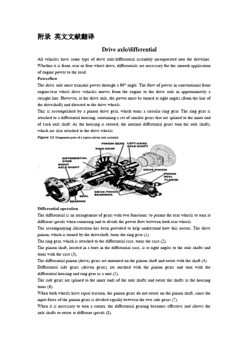
附录英文文献翻译Drive axle/differentialAll vehicles have some type of drive axle/differential assembly incorporated into the driveline. Whether it is front, rear or four wheel drive, differentials are necessary for the smooth application of engine power to the road.PowerflowThe drive axle must transmit power through a 90° angle. The flow of power in conventional front engine/rear wheel drive vehicles moves from the engine to the drive axle in approximately a straight line. However, at the drive axle, the power must be turned at right angles (from the line of the driveshaft) and directed to the drive wheels.This is accomplished by a pinion drive gear, which turns a circular ring gear. The ring gear is attached to a differential housing, containing a set of smaller gears that are splined to the inner end of each axle shaft. As the housing is rotated, the internal differential gears turn the axle shafts, which are also attached to the drive wheels.Figure 11 Component parts of a typical driven axle assembly.Differential operationThe differential is an arrangement of gears with two functions: to permit the rear wheels to turn at different speeds when cornering and to divide the power flow between both rear wheels.The accompanying illustration has been provided to help understand how this occurs. The drive pinion, which is turned by the driveshaft, turns the ring gear (1).The ring gear, which is attached to the differential case, turns the case (2).The pinion shaft, located in a bore in the differential case, is at right angles to the axle shafts and turns with the case (3).The differential pinion (drive) gears are mounted on the pinion shaft and rotate with the shaft (4). Differential side gears (driven gears) are meshed with the pinion gears and turn with the differential housing and ring gear as a unit (5).The side gears are splined to the inner ends of the axle shafts and rotate the shafts as the housing turns (6).When both wheels have equal traction, the pinion gears do not rotate on the pinion shaft, since the input force of the pinion gears is divided equally between the two side gears (7).When it is necessary to turn a corner, the differential gearing becomes effective and allows the axle shafts to rotate at different speeds (8).As the inner wheel slows down, the side gear splined to the inner wheel axle shaft also slows. The pinion gears act as balancing levers by maintaining equal tooth loads to both gears, while allowing unequal speeds of rotation at the axle shafts. If the vehicle speed remains constant, and the inner wheel slows down to 90 percent of vehicle speed, the outer wheel will speed up to 110 percent. However, because this system is known as an open differential, if one wheel should become stuck (as in mud or snow), all of the engine power can be transferred to only one wheel.Figure 12 Overview of differential gear operating principles.Limited-slip and locking differential operationLimited-slip and locking differentials provide the driving force to the wheel with the best traction before the other wheel begins to spin. This is accomplished through clutch plates, cones or locking pawls.The clutch plates or cones are located between the side gears and the inner walls of the differential case. When they are squeezed together through spring tension and outward force from the side gears, three reactions occur. Resistance on the side gears causes more torque to be exerted on the clutch packs or clutch cones. Rapid one wheel spin cannot occur, because the side gear is forced to turn at the same speed as the case. So most importantly, with the side gear and the differential case turning at the same speed, the other wheel is forced to rotate in the same direction and at the same speed as the differential case. Thus, driving force is applied to the wheel with the better traction. Locking differentials work nearly the same as the clutch and cone type of limited slip, except that when tire speed differential occurs, the unit will physically lock both axles together and spin them as if they were a solid shaft.Figure 13 Limited-slip differentials transmit power through the clutches or cones to drive the wheel having the best traction.Identifying a limited-slip drive axleMetal tags are normally attached to the axle assembly at the filler plug or to a bolt on the cover. During the life of the vehicle, these tags can become lost and other means must be used to identify the drive axle.To determine whether a vehicle has a limited-slip or a conventional drive axle by tire movement, raise the rear wheels off the ground. Place the transmission in PARK (automatic) or LOW (manual), and attempt to turn a drive wheel by hand. If the drive axle is a limited-slip type, it will be very difficult (or impossible) to turn the wheel. If the drive axle is the conventional (open) type, the wheel will turn easily, and the opposing wheel will rotate in the reverse direction.Place the transmission in neutral and again rotate a rear wheel. If the axle is a limited-slip type, the opposite wheel will rotate in the same direction. If the axle is a conventional type, the opposite wheel will rotate in the opposite direction, if it rotates at all.Gear ratioThe drive axle of a vehicle is said to have a certain axle ratio. This number (usually a whole number and a decimal fraction) is actually a comparison of the number of gear teeth on the ring gear and the pinion gear. For example, a 4.11 rear means that theoretically, there are 4.11 teeth on the ring gear for each tooth on the pinion gear or, put another way, the driveshaft must turn 4.11 times to turn the wheels once. Actually, with a 4.11 ratio, there might be 37 teeth on the ring gear and 9 teeth on the pinion gear. By dividing the number of teeth on the pinion gear into the number of teeth on the ring gear, the numerical axle ratio (4.11) is obtained. This also provides a good method of ascertaining exactly which axle ratio one is dealing with.Another method of determining gear ratio is to jack up and support the vehicle so that both drive wheels are off the ground. Make a chalk mark on the drive wheel and the driveshaft. Put the transmission in neutral. Turn the wheel one complete turn and count the number of turns that the driveshaft/halfshaft makes. The number of turns that the driveshaft makes in one complete revolution of the drive wheel approximates the axle ratio.Figure 14 The numerical ratio of the drive axle is the number of the teeth on the ring gear divided by the number of the teeth on the pinion gear.译文:驱动桥/差速器所有的车辆有一些类型的驱动桥/差速器总成包含在传动系统中。
最新外文翻译汽车差速器
外文翻译汽车差速器Failure analysis of an automobile differential pinion shaftAbstractDifferential is used to decrease the speed and to provide moment increase for transmitting the movement coming from the engine to the wheels by turning it according to the suitable angle in vehicles and to provide that inner and outer wheels turn differently. Pinion gear and shaft at the entrance are manufactured as a single part whereas they are in different forms according to automobile types. Mirror gear which will work with this gear should become familiar before the assembly. In case of any breakdown, they should be changed as a pair. Generally, in these systems there are wear damages in gears. The gear inspected in this study has damage as a form of shaft fracture.In this study, failure analysis of the differential pinion shaft is carried out. Mechanical characteristics of the material are obtained first. Then, the microstructure and chemical compositions are determined. Some fractographic studies are carried out to asses the fatigue and fracture conditions.Keywords: Differential; Fracture; Power transfer; Pinion shaft1. IntroductionThe final-drive gears may be directly or indirectly driven from the output gearing of the gearbox. Directly driven final drives are used when the engine and transmission units are combined together to form an integral construction. Indirectly driven final drives are used at the rear of the vehicle being either sprung and attached to the body structure or unsprung and incorporated in the rear-axle casing. The final-drive gears are used in the transmission system for the following reasons [1]:(a) to redirect the drive from the gearbox or propeller shaft through 90° and,(b) to provide a permanent gear reduction between the engine and the driving road-wheels.In vehicles, differential is the main part which transmits the movement coming from the engine to the wheels. On a smooth road, the movement comes to both wheels evenly. The inner wheel should turn less and the outer wheel should turn more to do the turning without lateral slipping and being flung. Differential, which is generally placed in the middle part of the rear bridge, consists of pinion gear, mirror gear, differential box, two axle gear and two pinion spider gears.A schematic illustration of a differential is given in Fig. 1. The technical drawing of the fractured pinion shaft is also given in Fig. 2. Fig. 3 shows the photograph of the fractured pinion shaft and the fracture section is indicated.In differentials, mirror and pinion gear are made to get used to each other during manufacturing and the same serial number is given. Both of them are changed on condition that there are any problems. In these systems, the common damage is the wear of gears [2–4]. In this study, the pinion shaft of the differential of aminibus has been inspected. The minibus is a diesel vehicle driven at the rear axle and has a passenger capacity of 15 people. Maximum engine power is 90/4000 HP/rpm, and maximum torque is 205/1600 Nm/rpm. Its transmission box has manual system (5 forward, 1 back). The damage was caused by stopping and starting the minibus at atraffic lights. In this differential, entrance shaft which carries the pinion gear was broken. Various studies have been made to determine the type and possible reasons of the damage.These are:studies carried out to determine the material of the shaft;studies carried out to determine the micro-structure;studies related to the fracture surface.There is a closer photograph of the fractured surfaces and fracture area in Fig. 4. The fracture was caused by taking out circular mark gear seen in the middle of surfaces.Fig. 1. Schematic of the analysed differential.Fig. 2. Technical drawing of the analysed pinion shaftFig. 3. The picture of the undamaged differential pinion analysed in the studyFig. 4. Photographs of failed shaft2. Experimental procedureSpecimens extracted from the shaft were subjected to various tests including hardness tests and metallographic and scanning electron microscopy as well as the determination of chemical composition. All tests were carried out at room temperature.2.1. Chemical and metallurgical analysisChemical analysis of the fractured differential material was carried out using a spectrometer. The chemical composition of the material is given in Table 1. Chemical composition shows that the material is a low alloy carburising steel of the AISI 8620 type.Hardenability of this steel is very low because of low carbon proportion. Therefore, surface area becomes hard and highly enduring, and inner areas becomes tough by increasing carbon proportion on the surface area with cementation operation. This is the kind of steel which is generally used in mechanical parts subjected do torsion and bending. High resistance is obtained on the surface and high fatigue endurance value can be obtained with compressive residual stress by making the surface harder [5–7].In which alloy elements distribute themselves in carbon steels depends primarily on the compound- and carbide-forming tendencies of each element. Nickel dissolves in the a ferrite of the steel since it has less tendency to form carbides than iron. Silicon combines to a limited extent with the oxygen present in the steel to form nonmetallic inclusions but otherwise dissolves in the ferrite. Most of the manganese added tocarbon steels dissolves in the ferrite. Chromium, which has a somewhat stronger carbide-forming tendency than iron, partitions between the ferrite and carbide phases. The distribution of chromium depends on the amount of carbon present and if other stronger carbide-forming elements such as titanium and columbium are absent. Tungsten and molybdenum combine with carbon to form carbides if there is sufficient carbon present and if other stronger carbide-forming elements such as titanium and columbium are absent. Manganese and nickel lower the eutectoid temperature [8].Preliminary micro structural examination of the failed differential material is shown in Fig. 5. It can be seen that the material has a mixed structure in which some ferrite exist probably as a result of slow cooling and high Si content. High Si content in this type of steel improves the heat treatment susceptibility as well as an improvement of yield strength and maximum stress without any reduction of ductility [9]. If the microstructure cannot be inverted to martensite by quenching, a reduction of fatigue limit is observed.Table 1Chemical analysis of the pinion gear material (wt%)Fe C Si Mn P S Cr Mo Ni 96.92 0.235 0.252 0.786 0.044 0.016 0.481 0.151 0.517 and fracture surfaces.Fig. 5. Micro structure of the material (200·).There are areas with carbon phase in Fig. 5(a). There is the transition boundary of carburisation in Fig. 5(b) and (c) shows the matrix region without carburisation. As far as it is seen in these photographs, the piece was first carburised, then the quenching operation was done and than tempered. This situation can be understood from blind martensite plates.2.2. Hardness testsThe hardness measurements are carried out by a MetTest-HT type computer integrated hardness tester. The load is 1471 N. The medium hardness value of the interior regions is obtained as 43 HRC. Micro hardness measurements have been made to determine the chance of hardness values along the cross-section because of the hardening of surface area due to carburisation. The results of Vickers hardness measurement under a load of 4.903 N are illustrated in Table 2.2.3. Inspection of the fractureThe direct observations of the piece with fractured surfaces and SEM analyses are given in this chapter. The crack started because of a possible problem in the bottom of notch caused the shaft to be broken completely. The crack started on the outer part, after some time it continued beyond the centre and there was only a little part left. And this part was broken statically during sudden starting of the vehicle at the traffic lights. As a characteristic of the fatigue fracture, there are two regions in the fractured surface. These are a smooth surface created by crack propagation and a rough surface created by sudden fracture. These two regions can be seen clearly for the entire problem as in Fig. 4. The fatigue crack propagation region covers more than 80% of the cross-section.Table 2Micro hardness values Distance from surface (lm) 50 100 200 400 CenterValues HV (4903N) 588 410 293 286 263Fig.Fig. 6. SEM image of the fracture surface showing the ductile shear.Fig. 7. SEM image of the fracture surface showing the beach marks of the fatigue crack propagation.Shaft works under the effect of bending, torsion and axial forces which affect repeatedly depending on the usage place. There is a sharp fillet at level on the fractured section. For this reason, stress concentration factors of the area have been determined. Kt = 2.4 value (for bending and tension) and Kt = 1.9 value (for torsion) have been acquired according to calculations. These are quite high values for areas exposed to combined loading.These observations and analysis show that the piece was broken under the influence of torsion with low nominal stresses and medium stress concentration [10].The scanning electron microscopy shows that the fracture has taken place in a ductile manner (Fig. 6). There are some shear lips in the crack propagation region which is a glue of the plastic shear deformations. Fig. 7 shows the beach marks of the fatigue crack propagation. The distance between any two lines is nearly 133 nm.3. ConclusionsA failed differential pinion shaft is analysed in this study. The pinion shaft is produced from AISI 8620 low carbon carburising steel which had a carburising, quenching and tempering heat treatment process. Mechanical properties, micro structural properties, chemical compositions and fractographic analyses are carried out to determine the possible fracture reasons of the component. As a conclusion, the following statements can be drawn:The fracture has taken place at a region having a high stress concentration by a fatigue procedure under a combined bending, torsion and axial stresses having highly reversible nature.The crack of the fracture is initiated probably at a material defect region at the critical location.The fracture is taken place in a ductile manner.Possible later failures may easily be prevented by reducing the stress concentration at the critical location.AcknowledgementThe author is very indebted to Prof. S. Tasgetiren for his advice and recommendations during the study.H. Bayrakceken / Engineering Failure Analysis 13 (2006) 1422–1428References[1] Heisler H. Vehicle and engine technology. 2nd ed. London: SAE International; 1999.[2] Makevet E, Roman I. Failure analysis of a final drive transmission in off-road vehicles. Eng Failure Anal 2002;9:579–92.[3] Orhan S, Aktu¨rk N. Determination of physical faults in gearbox through vibration analysis. J Fac Eng Arch Gazi University2003;18(3):97–106.[4] Tas getiren S, Aslantas K, Ucun I. Effect of press-fitting pressure on the fatigue damages of root in spur gears. Technol Res: EJMT2004;2:21–9.[5] Nanawarea GK, Pableb MJ. Failures of rear axle shafts of 575 DI tractors. Eng Failure Anal 2003;10:719–24.[6] Aslantas K, Tas getiren S. A study of spur gear pitting formation and life prediction. Wear 2004;257:1167–75.[7] Savas V, O¨ zek C. Investigation of the distribution of temperature on a shaft with respect to the deflection. Technol Res: EJMT2005;1:33–8.[8] Smith FW. Principles of materials science and engineering. 3rd ed. USA: McGraw-Hill Series; 1996. p. 517–18.[9] ASM metal handbook, vol. 1. Properties and selection, irons, steels, and high performance alloys; 1991.[10] Voort GFV. Visual examination and light microscopy. ASM handbook metallography and microstructures. Materials Park(OH): ASM International; 1991. p. 100–65.汽车差速器小齿轮轴的失效分析摘要差速器的作用是根据车辆合适的角度, 通过将运动转向, 为运动传输减速或者提供瞬间加速, 这个运动来自引擎, 到车轮去, 使内外车轮转动不同。
驱动桥和差速器中英文对照外文翻译文献
中英文对照外文翻译文献(文档含英文原文和中文翻译)原文:Drive axle/differentialAll vehicles have some type of drive axle/differential assembly incorporated into the driveline. Whether it is front, rear or four wheel drive, differentials are necessary for the smooth application of engine power to the road.PowerflowThe drive axle must transmit power through a 90°angle. The flow of power in conventional front engine/rear wheel drive vehicles moves from the engine to the drive axle in approximately a straight line. However, at the drive axle, the power must be turned at right angles (from the line of the driveshaft) and directed to the drive wheels.This is accomplished by a pinion drive gear, which turns a circular ring gear. The ring gear is attached to a differential housing, containing a set of smaller gears that are splined to the inner end of each axle shaft. As the housing is rotated, the internal differential gears turn the axle shafts, which are also attached to the drive wheels.Fig 1 Drive axleRear-wheel driveRear-wheel-drive vehicles are mostly trucks, very large sedans and many sports car and coupe models. The typical rear wheel drive vehicle uses a front mounted engine and transmission assemblies with a driveshaft coupling the transmission to the rear drive axle. Drive in through the layout of the bridge, the bridge drive shaft arranged vertically in the same vertical plane, and not the drive axle shaft, respectively, in their own sub-actuator with a direct connection, but the actuator is located at the front or the back of the adjacent shaftof the two bridges is arranged in series. Vehicle before and after the two ends of the driving force of the drive axle, is the sub-actuator and the transmission through the middle of the bridge. The advantage is not only a reduction of the number of drive shaft, and raise the driving axle of the common parts of each other, and to simplify the structure, reduces the volume and quality.Fig 2 Rear-wheel-drive axleSome vehicles do not follow this typical example. Such as the older Porsche or Volkswagen vehicles which were rear engine, rear drive. These vehicles use a rear mounted transaxle with halfshafts connected to the drive wheels. Also, some vehicles were produced with a front engine, rear transaxle setup with a driveshaft connecting the engine to the transaxle, and halfshafts linking the transaxle to the drive wheels.Differential operationIn order to remove the wheel around in the kinematics due to the lack of co-ordination about the wheel diameter arising from a different or the same rolling radius of wheel travel required, inter-wheel motor vehicles are equipped with about differential, the latter to ensure that the car driver Bridge on both sides of the wheel when in range with a trip to the characteristics of rotating at different speeds to meet the requirements of the vehicle kinematics.Fig 3 Principle of differentialThe accompanying illustration has been provided to help understand how this occurs.1.The drive pinion, which is turned by the driveshaft, turns the ring gear.2.The ring gear, which is attached to the differential case, turns the case.3.The pinion shaft, located in a bore in the differential case, is at right angles to the axle shafts and turns with the case.4.The differential pinion (drive) gears are mounted on the pinion shaft and rotate with the shaft .5.Differential side gears (driven gears) are meshed with the pinion gears and turn with the differential housing and ring gear as a unit.6.The side gears are splined to the inner ends of the axle shafts and rotate the shafts as the housing turns.7.When both wheels have equal traction, the pinion gears do not rotate on the pinion shaft, since the input force of the pinion gears is divided equally between the two side gears.8.When it is necessary to turn a corner, the differential gearing becomes effective and allows the axle shafts to rotate at different speeds .Open-wheel differential on each general use the same amount of torque. To determine the size of the wheel torque to bear two factors: equipment and friction. In dry conditions, when a lot of friction, the wheel bearing torque by engine size and gear restrictions are hours in the friction (such as driving on ice), is restricted to a maximum torque, so that vehicles will not spin round. So even if the car can produce more torque, but also need to have sufficient traction to transfer torque to the ground. If you increase the throttle after the wheels slip, it will only make the wheels spin faster.Fig 4 Conventional differentialLimited-slip and locking differential operationFig 5 Limited-slip differentialDifferential settlement of a car in the uneven road surface and steering wheel-driven speed at about the different requirements; but is followed by the existence of differential in the side car wheel skid can not be effective when the power transmission, that is, the wheel slip can not produce the driving force, rather than spin the wheel and does not have enough torque. Good non-slip differential settlement of the car wheels skid on the side of the power transmission when the issue, that is, locking differential, so that no longer serve a useful differential right and left sides of the wheel can be the same torque.Limited-slip and locking differential operation can be divided into two major categories:(1) mandatory locking type in ordinary differential locking enforcement agencies to increase, when the side of the wheel skid occurs, the driver can be electric, pneumatic or mechanical means to manipulate the locking body meshing sets of DIP Shell will be with the axle differential lock into one, thus the temporary loss of differential role. Relatively simple structure in this way, but it must be operated by the driver, and good roads to stop locking and restore the role of differential.(2) self-locking differential installed in the oil viscosity or friction clutch coupling, whenthe side of the wheel skid occurs when both sides of the axle speed difference there, coupling or clutch friction resistance on the automatic, to make certain the other side of the wheel drive torque and the car continued to travel. When there is no speed difference on both sides of the wheel, the frictional resistance disappeared, the role of automatic restoration of differentials. More complicated structure in this way, but do not require drivers to operate. Has been increasingly applied in the car. About non-slip differential, not only used for the differential between the wheels, but also for all-wheel drive vehicle inter-axle differential/.Gear ratioThe drive axle of a vehicle is said to have a certain axle ratio. This number (usually a whole number and a decimal fraction) is actually a comparison of the number of gear teeth on the ring gear and the pinion gear. For example, a 4.11 rear means that theoretically, there are 4.11 teeth on the ring gear for each tooth on the pinion gear or, put another way, the driveshaft must turn 4.11 times to turn the wheels once. The role of the final drive is to reduce the speed from the drive shaft, thereby increasing the torque. Lord of the reduction ratio reducer, a driving force for car performance and fuel economy have a greater impact. In general, the more reduction ratio the greater the acceleration and climbing ability, and relatively poor fuel economy. However, if it is too large, it can not play the full power of the engine to achieve the proper speed. The main reduction ratio is more Smaller ,the speed is higher, fuel economy is better, but the acceleration and climbing ability will be poor.翻译:驱动桥和差速器所有的汽车都装有不同类型的驱动桥和差速器来驱动汽车行驶。
汽车差速器中英文对照外文翻译文献
中英文对照外文翻译(文档含英文原文和中文翻译)Failure analysis of an automobile differential pinion shaft AbstractDifferential is used to decrease the speed and to provide moment increase for transmitting the movement coming from the engine to the wheels by turning it according to the suitable angle in vehicles and to provide that inner and outer wheels turn differently. Pinion gear and shaft at the entrance are manufactured as a single part whereas they are in different forms according to automobile types. Mirror gear which will work with this gear should become familiar before the assembly. In case of any breakdown, they should be changed as a pair. Generally, in these systems there are wear damages in gears. The gear inspected in this study has damage as a form of shaft fracture.In this study, failure analysis of the differential pinion shaft is carried out. Mechanical characteristics of the material are obtained first. Then, the microstructure and chemical compositions are determined. Some fractographic studies are 2005 Elsevier Ltd. All rights reserved.Keywords: Differential; Fracture; Power transfer; Pinion shaft1. IntroductionThe final-drive gears may be directly or indirectly driven from the output gearing of the gearbox. Directly driven final drives are used when the engine and transmission units are combined together to form an integral construction. Indirectly driven final drives are used at the rear of the vehicle being either sprung and attached to the body structure or unsprung and incorporated in the rear-axle casing. The final-drive gears are used in the transmission system for the following reasons [1]:(a) to redirect the drive from the gearbox or propeller shaft through 90°and,(b) to provide a permanent gear reduction between the engine and the driving road-wheels.In vehicles, differential is the main part which transmits the movement coming from the engine to the wheels On a smooth road, the movement comes to both wheels evenly. The inner wheel should turn less and the outer wheel should turn more to do the turning without lateral slipping and being flung. Differential, which is generally placed in the middle part of the rear bridge, consists of pinion gear, mirror gear, differential box, two axle gear and two pinion spider gears.A schematic illustration of a differential is given in Fig, 1. The technical drawing of pinion the fractured pinion shaft is also given in Fig, 2, Fig. 3 shows the photograph of the fractured pinion shaft and the fracture section is indicated.In differentials, mirror and pinion gear are made to get used to each other during manufacturing and the same serial number is given. Both of them are changed on condition that there are any problems. In these systems, the common damage is the wear of gears [2-4]. In this study, the pinion shaft of the differential of a minibus has been inspected. The minibus is a diesel vehicle driven at the rear axle and has a passenger capacity of 15 people. Maximum engine power is 90/4000 HP/rpm, and maximum torque is 205/1600 Nm/rpm. Its transmission box has manual system (5 forward, 1 back). The damage was caused by stopping and starting the minibus at a traffic lights. In this differential, entrance shaft which carries the pinion gear was broken. Various studies have been made to determine the type and possible reasons of the damage. These are:•studies carried out to determine the material of the shaft;•studies carried out to determine the micro-structure;•studies related to the fracture surface.There is a closer photograph of the fractured surfaces and fracture area in Fig. 4. The fracture was caused by taking out circular mark gear seen in the middle of surfaces.2. Experimental procedureSpecimens extracted from the shaft were subjected to various tests including hardness tests and metallographic and scanning electron microscopy as well as the determination of chemical composition. All tests were carried out at room temperature.2.1 Chemical and metallurgical analysisChemical analysis of the fractured differential material was carried out using a spectrometer. The chemical composition of the material is given in Table 1. Chemical composition shows that the material is a lowalloy carburizing steel of the AISI 8620 type.Hardenability of this steel is very low because of low carbon proportion. Therefore, surface area becomes hard and highly enduring, and inner areas becomes tough by increasing carbon proportion on the surface area with cementation operation. This is the kind of steel which is generally used in mechanical parts subjected do torsion and bending. High resistance is obtained on the surface and high fatigue endurance value can be obtained with compressive residual stressby making the surface harder [5-7].In which alloy elements distribute themselves in carbon steels depends primarily on the compound and carbide forming tendencies of each element. Nickel dissolves in the αferrite of the steel since it has less tendency to form carbides than iron Silicon combines to a limited extent with the oxygen present in the steel to form nonmetallic inclusions but otherwise dissolves in the ferrite. Most of the manganese added to carbon steels dissolves in the ferrite. Chromium, which has a somewhat stronger carbide-forming depends on the iron, partitions between the ferrite and carbide phases. The distribution of chromium depends on the amount of carbon present and if other stronger carbide-forming elements such as titanium and columbium amount of carbon present and if other stronger carbide-forming elements such as titanium and columbium are absent. Tungsten and molybdenum combine with carbon to form carbides is there is sufficient carbon present and if other stronger carbide-forming elements such da titanium and columbium are absent. Manganese and nickel lower the eutectoid temperature [8]. Preliminary micro structural examination of the failed differential material is shown in Fig. 5. It can be seen that the material has a mixed structure in which some ferrite exist probably as a result of slow cooling and high Si content. High Si content in this type of steel improves the heat treatment susceptibility as well asan improvement of yield strength and maximum stress without any reduction of ductility [9]. If the micro-structure cannot be inverted to martensite by quenching, a reduction of fatigue limit is observed.There are areas with carbon phase in Fig. 5(a). There is the transition boundary of carburization in Fig. 5(b) and (c) shows the matrix region without carburization. As far as it is seen in there photographs, the piece was first carburized, then the quenching operation was done than tempered. This situation can be understood from blind martensite plates.2.2 Hardness testsThe hardness measurements are carried out by a MetTest-HT type computer integrated hardness tester. The load is 1471 N. The medium hardness value of the interior regions is obtained as obtained as 43 HRC. Micro hard-ness measurements have been made to determine the chance of hardness values along cross-section be-cause of the hardening of surface area dueto carburization. The results of Vickers hardness measurement under a load of 4.903 N are illustrated in Table 2.2.3 Inspection of the fractureThe direct observations of the piece with fractured surfaces and SEM analyses are given in this chapter. The crack started because of a possible problem in the bottom of notch caused the shaft to be broken completely. The crack started on the outer part, after some time it continued beyond the centre and there was only a little part left. And this part was broken statically during sudden starting of the vehicle at the traffic lights. As a characteristic of the fatigue , there are two regions in the fractured surface. These are a smooth surface created by crack propagation and a rough surface created by sudden fracture. These two regions can be seen clearly for the entire problem as in Fig. 4. The fatigue crack propagation region covers more than 80% of the cross-section.Shaft works under the effect of bending, torsion and axial forces which affect repeatedlydepending on the usage place. There is a sharp fillet at level on the fractured section. For this reason, stress concentration factors of the area have been determined. K t = 2.4 value (for bending and tension), and K t = 1.9 value (for torsion) have been acquired according to calculations. These are quite high values for areas exposed to combined loading.These observations and analysis show that the piece was broken under the influence of torsion with low nominal stresses electron microscopy shows that the fracture has taken place in a ductile manner (Fig.6). There are some shear lips in the crack propagation region which is a glue of the plastic shear deformations. Fig. 7 shows the beach marks of the fatigue crack propagation. The distance between any lines is nearly 133 nm.3. ConclusionsA failed differential pinion shaft is analysed in this study. The pinion shaft is produced from AISI 8620 low carbon carburising steel which had a carbursing, quenching and tempering heat treatment process. Mechanical properties, micro structural properties, chemical compositions and fractographic analyses are carried out to determine the possible fracture reasons of the component. As a conclusion, the following statements can be drawn:•The fracture has taken place at a region having a high stress concentration by a fatigue procedure under a combined bending, torsion and axial stresses having highly reversible nature.•The crack of the fracture is initiated probably at a material defect region at the critical location.•The fracture is taken place in a ductile manner.•Possible later failures may easily be prevented by reducing the stress concentration at the critical locationAcknowledgementThe author is very indebted to Prof. S. Tasgetiren for his advice and recommendations during the srudy.References[1]Heisler H. Vehicle and engine technology. 2nd ed. London: SAE International; 1999.[2]Makevet E, Roman I. Failure analysis of a final drive transmission in off-road vehicles. EngFailure Anal 2002;9:579-92.[3]Orhan S, Aktu ¨rk N. Determination of physical faults in gearbox through vibrationanalysis. J Fac Eng Arch Gazi University 2003;18(3):97–106..[4]Tasgetiren S, Aslantas ? K, Ucun I. Effect of press-fitting pressure on the fatiguedamages of root in spur gears. Technol Res: EJMT 2004;2:21–9.[5]Nanawarea GK, Pableb MJ. Failures of rear axle shafts of 575 DI tractors. EngFailure Anal 2003;10:719–24.[6]Aslantas K, Tasgetiren S. A study of spur gear pitting formation and life prediction.Wear 2004;257:1167–75.[7]Savas V, O ¨ zek C. Investigation of the distribution of temperature on a shaft withrespect to the deflection. Technol Res: EJMT 2005;1:33–8.[8]Smith FW. Principles of materials science and engineering. 3rd ed. USA: McGraw-HillSeries; 1996. p. 517–18.[9]ASM metal handbook, vol. 1. Properties and selection, irons, steels, and highperformance alloys; 1991.[10]Voort GFV. Visual examination and light microscopy. ASM handbook metallographyand microstructures. Materials Park (OH): ASM International; 1991. p. 100–65.汽车差速器小齿轮轴的失效分析摘要差速器是用来降低速度增加扭矩并根据合适的角度向两轮传递动力。
- 1、下载文档前请自行甄别文档内容的完整性,平台不提供额外的编辑、内容补充、找答案等附加服务。
- 2、"仅部分预览"的文档,不可在线预览部分如存在完整性等问题,可反馈申请退款(可完整预览的文档不适用该条件!)。
- 3、如文档侵犯您的权益,请联系客服反馈,我们会尽快为您处理(人工客服工作时间:9:00-18:30)。
浅谈差速器普通行星齿轮差速器由行星架(差速器壳),半轴齿轮等零件组成。
它将发动机的动力,直接驱动差速器壳体内的轴,再由行星齿轮驱动左、右两半轴,并分别驱动左、右车轮。
差速器的设计应满足:左半轴转速与右半轴转速之和等于两倍的行星架转速。
当两侧车轮以纯滚动的形式做等距行驶时,会减少轮胎和路面的摩擦.差速器的这种调整是自动的,这里涉及到“最小能耗原理”,即地球上所有物体都倾向于耗能最小的状态。
例如把一粒豆子放入一个碗内,豆子会自动停留在碗底,而不会留在碗壁,因为碗底是能量消耗最低的位置(位能),它会自动选择静止(动能最小)而不会不断地运动。
同样的道理,汽车转弯时所有的驱动轮,左、右车轮与行星架的速度是相等的,而在汽车转弯时的三个平衡状态被破坏,导致内侧轮转速减小,横向轮RPM增加。
汽车差速器是驱动桥的主要部件。
其功能是传递两侧半轴的动力,同时允许两半轴以不同的速度旋转,同时能够满足按照国家标准的自动的最低能量消耗的趋势,在转弯时自动接受转向半径来调整右轮转速,由于横向摩擦轮拖动现象,内侧车轮有滑动现象,现在两个驱动轮可以产生两个相反方向的附加力,因此符合最小的能源消耗原理, 这不可避免地导致了两侧车轮的速度差,从而摧毁了三个平衡关系,并通过半轴齿轮体现出来。
迫使行星齿轮产生自转,使外侧半轴转速更快,内侧半轴减速,从而实现两侧车轮转速的差异。
如果任意一侧驱动轴上的驱动轮都使用一个整体的刚性连接,那么这两个轮子只能以相同的角度旋转。
所以,当车辆的转向轮驱动时,由于外侧车轮比内侧车轮横过的距离大,将使外侧车轮在滚动的同时产生延迟,内侧车轮在滚动的同时产生滑动。
即使车轮在凹凸不平的道路上跑直线,因为虽然道路是直,但轮胎滚动半径范围(轮胎制造误差,磨损不同,通过不均或气压不等所造成的车轮滑动)轮毂时,不仅会加剧轮胎的磨损滑动,增加动力性和燃油消耗,还能使车辆的转向困难,制动性能变得差.为了使车轮尽可能不会发生滑动的结构,必须保证车轮可以以不同的角度旋转。
轴间差速器:通常驾驶的轿车轮毂轴承支撑在主轴上,能够以任何角度旋转,驱动车轮分别与两根半轴刚性连接,在两根半轴之间有一个差速器,这种差速器称为轴间差速器。
如果使后轮轴成为一个整体,他将无法使两侧的车轮转速有差异,即不能做自动调整。
为了解决这个问题,早在一百年前,法国雷诺汽车公司创始人路易斯·雷诺设计了一个差速器。
现代汽车上的差速器通常是根据其工作特性分为齿轮式差速器和限滑差速器两大类。
1.开模差速器诺基开模差速器的结构是典型的行星齿轮组的结构,只有太阳轮和小齿轮环外是相同的。
在此行星齿轮组中,驱动轮是行星架,被动轮是两个太阳轮。
通过行星齿轮组,我们知道了它的传输性能,如果行星架作为主动轴,两个太阳轮的转速和旋转方向是不确定的,甚至两个太阳轮旋转方向是相反的。
该差速器特征是两个半轴传递转矩相同,在一个驱动车轮的情况下,如果驱动轴旋转,驱动力会均匀地粘附在驱动轮上,如果没有驱动轴,转速就会加快,连接的两个半部的差动轴的转矩方向相反的,用来驱动车辆前进,而且只有车轮的内侧,行星架和内侧的太阳轮之间由等速传动变成了减速传动,驾驶感觉高速弯道加速比直行更强大。
开模差速器的优点是在路面上安装的转向驱动上的最佳效果。
缺点是在一个驱动轮丧失附着力的情况下,另外一个驱动轮也没有行驶力。
开模差速器可以适应于前轴和后轴驱动器驱动的汽车,在任何铺平道路上行驶。
2.限滑差速器限滑差速器可以弥补开模差速器的部分越野缺陷,它是对开模差速器机构的提升,差速器壳侧之间的摩擦增加,对应于所述行星齿轮组来讲,是行星架和太阳轮之间增加了摩擦片,增加的太阳轮和行星架的自由旋转的阻力矩。
限滑差速器提供的附加扭矩,与摩擦片传递的功率和两个驱动轮的转速差有关。
在开模差速器结构中改善的限滑差速器,不能达到100%的限滑,因为限滑系数越高,车辆的性能越差。
限滑差速器有开模差速器传动装置的特点和机械的结构。
优点是能提供一定的限滑力矩,缺点是转弯性能变差,摩擦片的寿命有限。
限滑差速器一般适用于铺装路面或者轻度越野的情况下。
通常用于驱动器,前驱车一般不装,因为限滑差速器干涉转向和限滑系数,转向越大就限滑就越困难。
3. 锁式差速器(机械锁定检查,电锁,气动锁紧检查)为了保证越野车在复杂条件下的驾驶性能,通过一定机械结构的差速器锁定,实现两个半轴的同步旋转。
通过分析行星齿轮组来锁定行星齿轮组机构,保证行星架轮与太阳轮,两个太阳轮之间的传动比是1:1。
太阳轮和行星架上的锁,可以把这个行星架和行星齿轮锁死,还可以把两个太阳轮锁死。
锁止式差速器如果没有锁,在传动比固定为1:1的情况下,其传输特性和开模差速器完全一样。
这种差速器在越野上的优点不言而喻,最大的缺点是动力,差速器在锁止情况下,车辆转向极其困难,现有的单个车轮有可能承载发动机100%的转矩,半轴会因为扭矩过大而变形或破裂,车辆在转弯时两个半轴的转矩是相对的,如果两侧的轮胎附着力过大,将扭动半轴。
此外,这种差速器在车辆在执行锁止的过程中会产生较大的噪声。
4 .电子锁差速器电子锁差速器和上述开模差速器比较,在结构和特性上不发生改变,但通过使用ABS或EBD系统来实现制动单侧打滑车轮的运动,限制两个驱动轮旋转差,保证驱动轮的动力。
优点:安全性好,不会损坏车辆。
缺点:需要ABS,成本高;在恶劣的越野条件下,EBD系统这一电子产品变成了机械产品;和锁式差速器一样驱动力在单侧车轮上。
5.齿轮式差速器:当驱动轮的以不同的方式旋转时,差速器分配给转速较慢的驱动轮的转矩大于转速较快的驱动轮的转矩,这种差速器的转矩分配特性能满足汽车在良好路面移动的要求。
但是,当汽车在恶劣的道路上行驶时,会严重影响其通过性能。
例如当汽车的一个驱动轮进入泥泞的道路,虽然另一驱动轮在良好的道路,汽车往往不能前进(滑动)。
在泥泞道路上的这一点上驱动轮在原地滑动,在良好的道路车轮是静止的。
这是因为在泥泞道路上,车轮和道路表面之间的粘附的较小,道路只有通过这一轮的较小的反应转矩,因此,差速器分配给这一轮的转矩也小,虽然另一个驱动轮和更好的道路,以提高粘附性较大,但由于扭矩的平均分布特性,使此驱动轮也只能被分配到驱动轮滑移需要的转矩,从而使驱动力来克服行驶阻力,汽车不能前进和动机消耗在驱动轮的滑移。
在这个时候不能使汽车相对地面前进,消耗燃油,加速零件的磨损,尤其是轮胎磨损加剧。
有效的解决方法是:切片机打滑驱动轮下的泥土,或在此轮垫干土,碎石,树枝,干草等。
6.滑动差速器:为了提高汽车在劣质路面上的通过性能,一些越野车和豪华轿车都采用滑动差速器。
滑动差速器的特点是:当驱动轮在劣质的路面上发生侧滑时,可以使大部分甚至全部的转矩传递给在好的路面上的驱动轮,以致充分利用驱动轮的附着力,以产生足够的力量使汽车开始或者继续行驶。
1. 差速器壳体不可以有任何性质的裂纹,外壳和行星齿轮垫片,差速器半轴齿轮之间的接触,应是光滑没有凹槽的,如果有轻微的凹槽或磨损,经过研磨可以继续使用,否则就必须更换新的或者进行修复。
2.行星齿轮差速器壳和行星齿轮的嵌合时,间隙不得超过0.1-0.15毫米,半轴齿轮轴颈部和壳孔间隙配合,应该没有明显的松散感,否则必须更换新的或进行修复。
原文:Something about the differentialBy ordinary differential planetary gear, the planet round rack (differential shell) and half axle gears, etc parts. By the power of the engine, direct drive shaft into differential planetary wheel frame, again by the planets wheel drive left, right, two half shaft arerespectively driven wheels left and right. Differential design requirements meet: (left) + (right shaft speed shaft speed) = 2 (planets wheel frame speed). When sides wheel as pure rolling forms do isometric driving, reducingtire and the surface friction.Differential this adjustment is automatic, here involves " minimal energy consumption principle", namely earth all objects are inclined to consumption mini mum state. For example a grain of beans into a bowl, beans will automatically stays in the bowl bottom and never stay in bowl wall, because bowl bottom is lowest energy position (potential), it automatically select static (minimum) without constantly kinetic energy movement. In the same way, Wheel in cornering would all the automobile moher, left, right wheel and planetary wheel frame three speed equal in balance, while in the car when turning three equilibrium state is destroyed, cause the medial wheel speed decreases, and the lateral wheel RPM increases.Automotive differential is driven axle Lord pieces. Its function is to both sides half shaft transmission power, while allowing both si-des half shaft in different speed rotating, satisfy both so automatically tendency of the lowest energy consumption in accordance with state, automaticaly turning radiu adjusting right wheels speed When cornering, due to the lateral friction wheel dragged phenomenon, medial wheel have slip phenomenon, two driving wheel now can produce two opposite direction of additional force, as a result of minimal energy consumption principle", which inevitably leads on both sides of the wheel speed difference, thus destroyed three balance relationship, and through the half shaft are reflected in half axle gear, forcing planetary gear produce rotation, make the lateral half shaft speed faster,medial half axle planetismal, thus realize both sides wheel speed difference.If the drive wheels on either side of the drive axle shaft to theuse of a whole rigid connection,the two wheels can only at the sameAngle rotation. So, when the vehicle steering wheel drive, due to the lateral than medial wheels moved across the distance is big, will make the lateral wheels in rolling produced simultaneously slippery procrastinate, and medial wheels in rolling produced simultaneously slip. Even the car run straight road gravamen, because although pavement straight but tyres or rolling radius range (tyre manufacture error, weardifferent, by the uneven or pneumatic ranging caused by the wheels of sliding)Wheel when not only aggravate sliding tire wear,increase power and fuel consumption, still can make the vehicle steering difficulties,braking performance becomes poor.For the wheel as far as possiblewill not occur in the structure of sliding, must guarantee the wheelscan come with different Angle rotation.Axis between differential:usually driven wheel bearings for support on spindle, enable to any Angle rotation, and drive wheels respectively with two root half axle rigid connection, in between two root half shaft withdifferential. This differential also called shaft between differential.If after axles make it a whole, he couldn't do it on both sides of the wheel speed difference,namely can't do an automatic adjustment. In order to solve this problem, as early as in a hundred years ago, France Renaultautomotive company founder luis Renault will design a differential in this thing. Modern vehicles on the differential usually according to its work characteristics into gear type differential and slip differential two kinds big.1. Open-die differential The structure of the Cherokee open-die differential is typical of planetary gear set structure, only the sun wheel and outside the pinion gear ring are the same. In this planetary gear set, driving gear is planet shelf, passive round is two SUNS wheel. Through the planetary gear set the transmission properties we know, if the planet shelf as Zhudong Zhou, two SUNS wheel speed and rotation direction is not affirmatory, even two SUNS wheel rotation direction is the opposite.Vehicle condition, this differential moher, feature is to two and a half shaft transmission torque of the same. In a driving wheel impending case, if the drive shaft rotation, have adhesion is uniform the driving wheels of driving force, if there is no drive shaft rotation is accelerated,have adhesion the driving wheels driving force equals impending wheel Angle acceleration and rotary inertia of the product Vehicle turning tires don't skid condition, connect the two halves of the differential shafttorque direction is opposite, give the vehicle driving forward, andonly the inside of the wheel, the planet shelf and medial sun round by the isokinetic transmission between became deceleration transmission, driving sensation is accelerated speed corners than straight more powerful.The advantages of open-die differential is installed in the pavement turned driving on the best effect. Weakness is in a driving wheel loss adhesion, under the situation of another nor drivingforce.Open-die differential is the suitable scope that all paving road traffic, front axle and rear axle driver drive can be installed.2. Limited slip differentialLimited slip differential used for parts make up open-die differential transmission in off-road defects, it is in the open differential institution improved,and the differential shell side increase friction between gear piece, corresponding to the planetary gear set speaking, is the planet shelf and the sun round between increased friction slices, increase the sun wheel and planet shelf free rotating resistance torque.Limited slip differential provide additional torque, and friction slices transfer of power and two driving wheel rotation difference of concerned.In open-die differential structure to improve on LSD, cannot produce 100% limited slip, because the limited slip coefficient, the higher the vehicles to the characteristics of the poor.LSD have open-die differential transmission characteristics and mechanical structure. Advantage is to provide certain limited slip torque,defect is turning performance becomes poor, friction slices limited life.LSD is the suitable scope paving road surface and mild off-road. Usually used for the drive. Former drove generally does not installed, because LSD interfere steering,limited slip coefficient, the greater the steering the more difficult.3. The lock type differential(mechanical locking check, electric the lock, pneumatic locking check)In order to guarantee the off-road vehicles in complex conditions, driving performance through certain mechanical structure of the differential locked achieve two half axle synchronous rotation. Through the analysis of planetary gear set is the planetary gear set of gearmechanisms locked, guarantee the planet shelf wheel with the sun, and two SUNS round between the transmission ratio between is 1:1.Can the sun to the wheel and planet shelf the lock, can put the planetshelf and planetary gear locked,still can put two SUNS wheel locked.The lock type differential,without the lock, its transmission characteristics and open-die differential exactly the same as that in the lock, under the situation of transmission ratio was fixed for 1:1.The advantages of this differential in off-road self-evident that provides the biggest drawback is the driving force, the differential lock up the situation, vehicle steering extremely difficult, Existing single wheel inherit engine 100% torque possible, half shaft will because torque excessive deformation or break, Vehicles in the process of steering bearings two and a half by opposite torque, if both sides tires adhesion are large, would wring half axle.Moreover, this kind of differentials, the vehicle process execution lock up the action will produce larger noise.4 . Electronic differentials lockElectronic differentials lock and the aforesaid compared,without changing the structure and characteristics of open-die differential, but use ABS or EBD system to implement unilateral braking skid wheels movement, limit of two driving wheel rotation difference, guarantee the drive wheels momentum.Advantages: good safety,won't damaged vehicle. Faults:need ABS and costly; EBD system, In the harsh off-road conditions, electronic product reliability as mechanical products; Unilateral wheel driving force, as the lock type differential.5. gear type differential:When driving wheel rotation difference exists about when, differential assigned to slow turns driving wheel torque is greater than turn fast driving wheel torque. This kind of differential torque partitioningcharacteristics can satisfy the car in good pavement moving. But when the automobile in bad the road, but serious influence through capacity. E.g. when a car driving wheel into muddy road, although another driving wheel in good road,the car was often cannot advance (known as slips). At this point in the muddy road on the driving wheels in-situ slip, in good roadwheels is motionless. This is because in the muddy road wheels and road surface adhesion between the lesser, road only through this round of half-and-half shaft role of smaller reaction torque,therefore differential assigned to this round of torque also small,although another driving wheel and better road to improve adhesion of the larger, but because average distribution characteristics of torque, which make this drive wheelscan only also assigned to the drive wheels with slip equalamounts of torque, so that the driving force to overcome driving resistance, cars can't advance and motivation is expended in slip driving wheel. At this time to floor not only made the car ahead,instead of waste fuel, accelerate parts wear, especially tire wear is intensified.Effective solutions are: slicer slip driving wheel under the mud or in this wheel mat dry soil, gravel, branches, hay,etc.6. slip differential:In order to improve the car in a bad way through capacity, some off-road vehicle and limousines screwup slip differential. Slip differential characteristics are,when driving wheel in a bad way side slip, can make the most or all torque in good road to the driving wheels, to take full advantage of the drive wheels adhesion to generate enough force, that carstart or continue to drive.1. Differential shell there cannot be any properties of crack, shell and planetary gear gaskets,differential half axle gear contact between, should be smooth without groove, If there is a slight groove or wear, can continue to use after grinding, otherwise must be changed or be repaired.2 the planetary gear differential shell and planetary gear wheel when the fitting clearance must not be more than 0.1-0.15 mm, half axle gear shaft neck and shell with holes for clearance fit, should have no obvious loose feeling, otherwise desert must be changed or repair.五分钟搞定5000字毕业论文外文翻译,你想要的工具都在这里!在科研过程中阅读翻译外文文献是一个非常重要的环节,许多领域高水平的文献都是外文文献,借鉴一些外文文献翻译的经验是非常必要的。