HS50 操作培训
【最新】hs50-word范文模板 (9页)

本文部分内容来自网络整理,本司不为其真实性负责,如有异议或侵权请及时联系,本司将立即删除!== 本文为word格式,下载后可方便编辑和修改! ==hs50篇一:HS5056使用说明书使用说明书产品名称:凝汽式汽轮机产品代号:HS5056 产品型号:N10-1.25目录1. 前言..............................................................................1 2. 汽轮机的技术规范及结构说明 (2)2.1 技术规范...................................................................2 2.2 机组结构及布置说明......................................................5 2.3 汽水系统...................................................................5 2.4 调节系统和保安系统......................................................6 2.4.1 调节和控制概述...........................................................6 2.5 供油系统 (7)2.5.1 供油系统概述................................................................ 72.6主要部套简介................................................................ .. (8)3.1 安装前的准备工作..........................................................17 3.2 安装 (17)3.汽轮机的安装 (17)4.起动和运行 (19)4.1 起动前的准备................................................................19 4.2 起动.............................................................................19 4.3 停机.. (20)5. 运行维护及停机保养………………...……...….………..….216. WW505程序卡 0-0350-5056-2201. 前言本说明书向用户简单介绍汽轮机的结构及其一般特性, 帮助用户了解该机组的性能和结构特点, 用户和安装单位在编制详细的安装和操作规程时可作为参考。
西格玛安全截止阀S 50产品信息说明书

Safety Shut-Off ValveS 50Product informationAC Accuracy classAG o Upper response pressure group AG u Lower response pressure group BV Breather valveGPR Gas pressure regulator HDS High-pressure spindle K G Valve flow rate coefficient p Pressure p d Outlet pressure p df SRV closing pressure p do SRV opening pressure p ds Setpoint of the response pressurep ds oUpper SSV response pressure p ds u Lower SSV response pressure p f,max Maximum closing pressure PS Maximum allowable pressure p u Inlet pressureQ n Standard volumetric flow rate RE Diaphragm assembly RSD2 Throttle valveSSV Safety shut-off valve SRV Safety relief valveSG Closing pressure group t Gas Gas inlet temperature VS Valve seatw d Outlet gas velocity w uInlet gas velocityW ds o Upper spring adjustment range (SSV)W ds u Lower spring adjustment range (SSV)Δp Pressure difference from inlet pressure to outlet pressure Δp wo Min. re-engagement difference between upper response pressure and normal operating pressure Δp wu Min. re-engagement difference between lower response pressure and normal operating pressure ρn Gas densityTable of ContentsApplication, Characteristics, Technical Data 4Application 4Characteristics 4Type of models / Options (see page 10) 4Technical data 5Structure and function 6Sectional view 7SSV setpoint spring table - control device 8Dimensions, Connection, and Weight 9Dimensional drawing 9Dimensions and weight 9Connection of the measuring lines and breather lines 9Types of Models / Options 10Design 11Properties of Gases 11Order Data 12Notes 13Contact 14Notes 16Observe the following publications in relation toinstallation, start-up and maintenance: DVGW - work sheets G 491 and G 600Operating and Maintenance Instructions S50ATTENTION List of abbreviations and formula symbolsApplication, Characteristics, Technical DataApplicationSafety shut-off valve (SSV), direct-acting (operating without auxiliary power), for systems acc. to DVGW work sheets G 491 (A) and G 600 (A) (TRGI)Can be used for the gases defined in DVGW work sheet G 260 / G 262 and neutral non-aggressive gases. (other gases on request)Characteristics• Integral pressure-tight version (IS)• High flow rate capacity• Open-air model• with BV breather valve• with electric position indicator SSV 'Closed' via inductive proximity initiator or via reed contact • with SSV electromagnetic remote release when power is applied or in case of power failure• with SSV manual release• oxygen model• hydrogen modelResponse pressure groupsLower response pressure AGu incommand area wdsu AG U Upper response pressure group AGoin command area wdsoAGo10 mbar to 50 mbar2050 mbar to 500 mbar10> 50 mbar10> 500 mbar5 Type of models / Options (see page 10)Technical dataType S 50ModelIntegral pressure-tight (IS)Max. allowable pressure PS 3 barNominal width Rp 1“ (DN 25), Rp 1½“ (DN 40), Rp 2“ (DN 50)(NPT thread on request)Standard volumetric flow rate Q n,max Rp 1“: 100m³/h, Rp 1½“: 300m³/h, Rp 2“: 300m³/h Type of connection Internal thread acc. to EN 10226-1MaterialHousing / actuator housing/ Control device housing Al cast alloy DIN EN 1706-AC-42100 ST6Corrosivity categoryDIN EN ISO 12944-2C1 to C5-I without additional coatingsC5-Man epoxy resin coating is recommended (see page10)Temperature range, Class 2-20°C to +60°C (operating/ambient temperature)Function, strength and tightness DIN EN 14382CE mark acc. to PED/ PIN number C E -0085-BS0420Ex protection The mechanical parts of the device do not have anypotential ignition sources of their own and therefore do not fall within the scope of ATEX 95 (94/9/EC). Electrical components fitted to the devicecomply with the ATEX requirements.Preferred installation positionThe safety shut-off valves (SSV) shall be installed in the pipeline preferably in horizontal position. For all nominal widths, the direction of flow is indicated by an arrow on the housing.Note: Observe the following documents in relation to installation, start-up, and maintenance:• DVGW - work sheets G 491 and G 600• Operating and Maintenance Instructions S50Installation upside down only after consultation with Medenus GmbHStructure and functionThe safety shut-off valve S 50 shuts off the gas flow when the outlet pressure in the regulation section exceeds or falls below a certain response pressure. To this end, the outlet pressure to be monitored is passed on to the SSV control device via a separate measurement line. As a function of the change in pressure, the diaphragm in the control device is raised or lowered. When the outlet pressure in the regulation section falls below the lower switch-off point or exceeds the upper switch-off point, the switch socket connected to the SSV diaphragm will move to the corresponding disengaging position, the balls of the engaging mechanism will release the SSV screw spindle, and the closing spring will press the SSV valve plate against the valve seat. The SSV actuator shuts off the gas flow gas-tight.The SSV can only be opened by hand and engaged in the open position. To do so, the outlet pressure at the measuring point must be lowered below the upper response pressure or raised above the lower response pressure by at least the re-engaging differential amount (Δp).The SSV can, except where otherwise stipulated in specific national legislation, be used in either functional class A (with diaphragm rupture protection) or B (without diaphragm rupture protection).There is also the option of using a remote display for the SSV position “CLOSED” and a manual and remote release when power is applied or in case of power failure.Installation exampleP 1P 2m in . 5x D NInlet OutletRange formeasuring points*(approx. 3x DN P 2)*) Recommended max. velocity at the measurement line port 25 m/sKSN75DF100S50SL10R50Sectional viewActuator housingValve seatActuatorBall detentRe-engagement unitDiaphragmSetting screw for lowerresponse pressureSetting screw for upperresponse pressure*) Standard spring**) If the control device is set up for simultaneous monitoring of upper and lower response pressures, the differencebetween the setpoints for the upper and lower response pressures (pdso and pdsu) should be at least 10% greater than thetotal of values given for Δpwo and Δpwu.SSV setpoint spring table - control deviceB ALYDimensions, Connection, and WeightDimensional drawingConnection of the measuring lines and breather linesNominal width MeasurementlineBreather lineDN 025 Rp 1“Connection* for: tube 12 x 1.5 (thread G 1/4)DN 040 Rp 1½“DN 050 Rp 2“Reactivation of SSVDimensions and weightInductivetransmitterSignal transmitterTypes of Models / OptionsSSV manual and remote releaseReed contacts and inductive transmittersare used to monitor the position (closed oropen position) of the safety shut-off valvevia remote display.Reed contact / inductive transmitterThe direct-acting safety solenoid valve is used aselectromagnetic remote release for closing the safetyshut-off valve when power is applied or in case of powerfailure.To protect the gas pressure regulator from externalinfluences, starting from a corrosivity category C5-M werecommend an epoxy resin coating.Epoxy resin coating in RAL colorsTypes of modelsOxygen version O2Hydrogen version H2(with helium leak test)The BV breather valve is used as for securing the installationroom against inadmissible escape of gas from diaphragmcomparator compartments of safety shut-off valves. In case ofa defect, the impermissible escape of gas into the surroundingatmosphere is limited to a maximum of 30l/h (air).It also serves as a substitute for an expensive and complexinstallation of breather lines.(Option not available for hydrogen version H2)BV breather valve BV breather valveDesignExample:Checking the gas velocitiesw = 380 ∙ Q n / (DN² ∙ p abs )Note: The factor 380 refers to an operating gas temperature fromapprox. 15°C to 20°C. For other temperatures, the velocity must be corrected as follows: w corr = w ∙ (t gas + 273.15) / 290Recommended max. gas velocity at the inlet flange:50 - 70 m/s Lower value for redirections upstream of the SSVInlet and outlet nominal width of the pipeline according to the selected device: 25 mm Q n = 70m³/h p u / (p d ) = 5 bar w u = 380 ∙ 70 / (25² ∙ 6) = 7.1 m/sDetermining the upper response pressureOutlet pressure P d(mbar)Upper response pressure W dso≤200P d +100 mbar >200 - ≤800P d x 1.5>800 - ≤1600P d x 1.3>1600P d +500 mbarPressure loss formulaCalculation pressure absolute (p u +1 bar)= p u,absΔp = Q nK Gx1000p u,abs2Properties of Gases• for natural gas (ρn = 0.83 kg/m³; t = 15°C)•f - natural gas conversion factor- LGas f Hs,n Gas f Hs,n [kWh/m³] [kWh/m³]Acetylene 0.84 16.25 Sewage gas 0.84 Ammonia 1.04 4.83 Carbon monoxide 0.81 3.51Butane 0.55 37.23 Carbon dioxide 0.65 -Chlorine 0.51 - Air 0.80 -Landfill gas approx. 0.80 Methane 1.08 11.06Natural gas L 1.00 9.77 Propane 0.64 28.03Natural gas H 1.03 11.45 Oxygen 0.76 -E thane 0.78 19.55 Sulphur dioxide 0.53 -E thylene 0.97 16.516 Nitrogen 0.81 -Mine gas (30% CH4) 0.86 Hydrogen 3.04 13.43Helium 2.15 -Order DataSafety shut-off S50/Rp1“/MD-R/left/BV/N/H/WAZ/SoIn every selection group, only one option can be selected in each case.............................................................................. ............................................................................. ............................................................................. ............................................................................. ............................................................................. ............................................................................. ............................................................................. ............................................................................. ............................................................................. ............................................................................. ............................................................................. ............................................................................. ............................................................................. ............................................................................. ............................................................................. ............................................................................. ............................................................................. ............................................................................. ............................................................................. ............................................................................. ............................................................................. ............................................................................. ............................................................................. .............................................................................If you want to know more about solutions from MEDENUS for the gas industry, please contact your local contact person or go to our internet site at www.medenus.de Trade representation worldwide medenus.de/de/kontakt.htmlManagementALEXANDER CHRISTIANI Phone: +49 (0) 2761 / 82788-18Mail:***********************Head of Sales & Marketing FRANZ FEICHTNERPhone: +49 (0) 2761 / 82788-26Mobile phone: +49 (0) 151 / 51002711Mail:**********************Technical Inside Sales Department MINDAUGAS PECKAITISPhone: +49 (0) 2761 / 82788-23Mail:**********************Inside Sales Department SEBASTIAN HUCKESTEINPhone: +49 (0) 2761 / 82788-11Mail:***********************MEDENuSGas-Druckregeltechnik GmbHIm Langen Feld 3D-57462 Olpe Phone: +49 (0)2761 82788-0Fax: +49 (0)2761 82788-9Mail:***************Internet: www.medenus.deInside Sales Department STEFANIE MÜLLERPhone: +49 (0) 2761 / 82788-13Mail:********************Head of Inside Sales Department MANUEL SCHEPPPhone: +49 (0) 2761 / 82788-20Mobile phone: +49 (0) 170 / 6355309Mail:*******************Notes .............................................................................. .............................................................................. .............................................................................. .............................................................................. .............................................................................. .............................................................................. .............................................................................. .............................................................................. .............................................................................. .............................................................................. .............................................................................. .............................................................................. .............................................................................. .............................................................................. .............................................................................. .............................................................................. .............................................................................. .............................................................................. .............................................................................. .............................................................................. .............................................................................. .............................................................................. .............................................................................. ..............................................................................Deutsch:http://medenus.de/files/upload/downloads/S50/Pi_S50_de.pdfEnglish:http://medenus.de/files/upload/downloads/S50/Pi_S50_en.pdfIn the download area of our homepage, this document is available in different languages. You can use the following QR codes and links to go directly to this document in your language.MEDENuS Gas-Druckregeltechnik GmbH Phone +49 (0)2761 82788-0Fax +49 (0)2761 82788-9Im Langen Feld 3 / D-57462 Olpe***************www.medenus.de。
渡边50切片机-培训资料

如图固定后拧上限位螺丝
31- 31
Shanghai Ishida Electronic Scales Ltd., Co.
擦拭干净后重新抹上黄油
将螺丝拧上后,用扳手加固
将开关部件上的银色外圈拧上
32- 32
Shanghai Ishida Electronic Scales Ltd., Co.
按上黑色开关的时候,注意按照如图所示的方向
厚
厚
度
度
相
相
差
差
较
较
大
小
大曲饼上方取下螺丝
联动轴下方的螺丝
拧下左右两侧下方各一个螺丝
9- 9
Shanghai Ishida Electronic Scales Ltd., Co.
注意左右两侧都各有一个黑色的垫圈
10- 10
Shanghai Ishida Electronic Scales Ltd., Co.
28- 28
Shanghai Ishida Electronic Scales Ltd., Co.
先只需固定一个限位螺丝,之后还要调整厚薄刻度
将螺丝拧上固定
29- 29
Shanghai Ishida Electronic Scales Ltd., Co.
将螺丝拧紧后调节到所示位置
30- 30
Shanghai Ishida Electronic Scales Ltd., Co.
你到最后一个螺丝,如果套筒伸不进去,可以适量的将曲柄往外拔一点
17- 17
Shanghai Ishida Electronic Scales Ltd., Co.
依次取下以上器件
18- 18
Shanghai Ishida Electronic Scales Ltd., Co.
siemens HS50培训资料_2
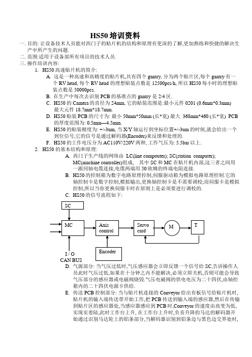
HS50培训资料一.目的: 让设备技术人员能对西门子的贴片机的结构和原理有更深的了解,更加熟练和快捷的解决生产中所产生的问题.二.范围:适用于设备部所有项目的技术人员.三.操作培训内容:1.HS50高速贴片机的简介:A. 这是一种高速和高精度的贴片机,共有四个gantry, 分为两个贴片区,每个gantry有一个RV head, 每个RV head 的理想贴装点数是12500pcs/h, 所以HS50每小时的理想贴装点数是50000pcs.B. 在生产中每次去识别PCB的基准点的gantry 是2/4区.C.HS50的Camera的直径为24mm, 它的贴装范围是:最小元件0201 (0.6mm*0.3mm)最大元件 18.7mm*18.7mm.D.HS50贴装PCB的尺寸为: 最小 50mm*50mm (长*宽) 最大 368mm*460 (长*宽) PCB的厚度范围为: 0.5mm—4.5mm.E.HS50的贴装精度为: +/-3um, 当X/Y轴运行到坐标位置+/-3um的时候,就会给出一个到位信号,它的信号是通过解码器(Encoder)来反馈和处理的.F.HS50的工作电压分为AC110V/220V两种, 工作气压为: 5.5bar以上.2.HS50 的基本结构和原理:A.西门子生产线的网络由 LC(line compouter); SC(station computer);MC(machine controller)组成, 其中SC和MC 在贴片机内部,这三者之间用一跟同轴电缆连接,电缆两端用50欧姆的终端电阻连接.B.HS50的控制箱为数字电路原理控制,伺服驱动箱为模拟电路原理控制.它的轴控制卡是数字控制,模拟输出,更换轴控制卡是不需要调校;而伺服卡是模拟控制,所以当你更换伺服卡时在原则上是必须要进行调校的.C.HS50的信号流程如下:D.气源部分: 当气压过低时,气压感应器会立即反馈一个信号给SC,告诉操作人员此时气压过低,如果在十分钟之内不能解决,必须立即关机,否则可能会导致气压部分的感应器或电磁阀烧毁.气压电磁阀的供电电压为二十四伏,由轴控箱内的二十四伏电源卡供给.E.传送PCB控制部分: 当与贴片机连接的Conveyor给出有板信号给贴片机时,贴片机的输入端传送带开始工作,把PCB传送到输入端的感应器,然后在传输到贴片区的感应器处,当感应器感应到PCB时,Conveyor的速度由高变为低,实现实着陆,此时工作台上升, 在工作台上升时,负责升降的马达的解码器开始通过识别马达轮上的铝条部分,当解码器识别到铝条边与黑色边交界处时,会给出一个到位信号给马达,此时马达会刹车停止. 在拆装工作台下马达的电源线时,应切记用手按住电源插头的底部,以防止损坏电源插头.传送PCB到下一个传输带所需要的信号包括:1. 请求信号2. 允许过板信号3. 到板信号4. 有板信号F.自动更换吸嘴部分: 它的控制原理为: 进气电磁阀气动电机吸嘴盒, 此装置工作时所需的气压压力为5bar, 且可以通过进气阀来调节气压压力.G.切刀部分: 切刀是通过两个气缸来实现控制的, 它的左右两个气缸的进气管接插方式不同,左边气管的接插方式为交叉式,切刀的背刃是双边刃,所以切刀的两边是可以对调过来使用的, 它通过调节气缸上的感应器来调节切刀动作的行程.切刀的信号连接是用CAN BUS(总线控制模式来实施的,用跳线来区分.在SITEST内可以读出切刀的\控制板的版本,以此来判断切刀控制是否OK.H.供料器工作台(简称料车)部分: HS50的料车电源与其他机型不同,因为它的电源是主机供给的,当机器每完成一个吸料循环时,它会供给切刀一个切料带的信号,此时切刀就会动作一次.所以料车有问题时,也有可能是切刀有问题造成的.料车的EPROM版本与机器内Software版本不一致时,可以进入SITEST内手动设置和装载料车EPROM的版本.I.RV Head(旋转头)部分:a. HS50的旋转头有十二个Segment,共装有十二个Sleeve,主要是用来执行吸取/识别/贴装元件动作的.它在正常情况下的贴装过程如下: 取料真空值检查旋转元件到指定贴片角度元件照相识别检查贴片角度贴片在这个过程中有任何一项如果不能通过,则会执行抛料动作再重新开始.b. 真空气路部分: 分为大小两路真空, 大的一路是用来提供在吸取元件后保持吸嘴上的元件时所需的真空,小的一路是用来提供吸取元件时所需的真空 ,这两个真空回路都是通过同一个真空发生器来执行的,通过真空测试板来测试这两个回路的真空值,这两路真空通过分配器将气压分配至各个转换气阀(既Plunger valve assy), 再通过吸取驱动马达(placement valve driver)和抛弃驱动马达(reject valve driver)来驱动活塞(plunger)来打开和关闭吸嘴吸取/贴装/抛弃元件所需要的气压.c. 头板: 主要是用来处理光栅尺信号,转换电机电压,处理真空测试板所反馈的信号的.头板的信号反馈和控制是通过Can Bus来实现,所以每个贴片区的头板信号是通过跳线来区分的.d. 角度控制马达(Dp Motor):主要是用来通过旋转Sleeve的角度来达到贴装元件所要求的角度的.它自带一个30V的测速电机来检测自身的旋转速度, 在它完成旋转角度后,会通过角度旋转扫描器(DP Scanner)来检测它旋转的角度是否正确.角度旋转扫描器与Sleeve光栅尺表面的间距为1.5mm+/-0.1mm.e. 元件识别照相和PCB识别照相机(Component Camera/PCB Camera): 元件识别照相机(简称CC)是根据程序内的元件库来识别元件的尺寸外形,以此找出元件的贴装中心点,它共有三种灯光控制,分别为: Plane Middle Steep, 我们可以通过调节这三种光来使CC识别元件时能达到一个好的效果;PCB识别照相机(简称PC)是根据程序内的基准点资料来识别PCB的基准点,算出PCB的准确位置,让元件贴装的位置更加精确,它的照明和照相是分开的,照明有CANBus来控制,照相由ICOS(图形处理卡)卡来控制.CC与PC的所有图形处理都要经过ICOS卡来处理,HS50共有两张ICOS卡,分别处理两个贴装区的元件识别和PCB识别所产生的图像,并提供相关的资料给MC和SC.f. Z轴控制部分: Z轴是通过Z轴马达工作传动Z轴滑轨来执行Segment上下的取料动作的,它通过上限和下限的感应器来反馈Z轴的行程,即我们所说的Top/Bottom Sensor.-> Fast CAN-Bus(500kBit/s)Units controlled by CAN Bus controller head boardSlow CAN Bus (125KBit/s)Z-axis bottom sensor 1.3mmValve driver mechanical position 0.2mmfeeler gauge 0,4 mmdistance with the aid of the 5/10 gauge 0.5mmAssembly race wayAssembly race star motorZ-axis upper 0.4mmUse0.01mm,0.02mm,0.03m m feeler gauge真空发生器原理:5个进气管,两个出气管(真空发生器里有两个喷嘴),小的透明管叫 pick up气路,供给segment 1位置;大的透明管叫holding气路,通过真空分配器供给2~12号位置。
E+H 50系列电磁流量计简明操作手册
按 键进入菜单,仿真结束后SIMULATION CURR:OFF。 输入密码:0050,也可以直接输入“50” ,当从左向右数第三个“*”号变成回车键后按“E”确认就可。
仿真电流输出,仿真结束后改 OFF
仿真电流
该资料仅供参考,若有异议,请以随设备附带的操作手册为准
50系列电磁流量计脉冲设置
按键控制 同时按 按 键, 键 键并保持3秒以上直接回到主显示页位置,同时 键步步退出功能矩阵到主显示页位置,同时按 键取消数据输入。
口径mm 小流量切 除 (v ~ 0.04 m/s) 口径mm 小流量切 除 (v ~ 0.04 m/s) 口径mm 小流量切 除 (v ~ 0.04 m/s) 口径mm 50 2" 5 dm3/min 65 – 8 dm3/min 80 3" 12 dm3/min 100 4" 20 dm3/min 125 30 dm3/min 150 6" 2.5 m3/h 200 8" 5.0 m3/h 250 10" 7.5 m3/h 300 12" 10 m3/h
50系列电磁流量计的简明操作手册
目录 50系列电磁流量计启动显示和按键操作说明 2、 50系列电磁流量计快速设置 3、 50系列电磁流量计修改单位 4、 50系列电磁流量计量程范围设置 5、 50系列电磁流量计电流输出仿真 6、 50系列电磁流量计脉冲设置 7、 50系列电磁流量计脉冲输出仿真 8、 50系列电磁流量计小流量切除功能 9、 50系列电磁流量计空管检测功能 10、 50系列电磁流量计累积流量设置和复位
OFF – ON SPECIAL – OED – ON STANDARD OFF:(即没有激活EPD,也没有激活OED) ON SPECIAL(只用于DN<400): 用于分离型仪表(传感器和变送器分开安装),开启的空管检测功能 OED:开启开路电极检测(OED) ON STANDARD:开启空管检测功能,用于: ---一体化仪表(传感器和变送器组成一个机械单元) ---应用在测量管内衬和测量管电极,产生介质的覆盖层。 出厂设置:OFF 注意: 只有当传感器安装EPD电极,ON STANDARD 和ON SPECIAL才可选。 设备交货时,EPD/OED功能的缺省设置是OFF,这个功能根据需要必须激活。 设备在工厂标定是用水标定(大约500us/cm),如果流体的电导率与这个参考的电导率有偏差的话,就 需要在现场重新做空管/满管校正。(看EPD/OED ADJUSTMENT功能) 在你开启EPD/OED功能之前,调整系数必须是有效的。如果这些系数不是有效的,则显示EPD/OED ADJUSTMENT (6481)功能。 如果在调整中有问题,则在显示器上出现下列错误信息: ——ADJUSTMENT FULL = EMPTY: 空管和满管的校正值是相同的,在这种情况下,必须重新做空管校正/满管校正。 ——ADJUSTMENT NOT OK: 由于介质的电导率已经超过所需的范围,校正式不可以进行的。
EH-HS50使用说明书

ALWAYS FOLLOW THESE IMPORTANT SAFETY INSTRUCTIONS!
After reading these safety instructions, ensure they are kept in a place allowing easy viewing at all times by the appliance user. Electrical Conditions
负离子发射口的清洁方法
EH-HS50_CH.indb
5
Safety Instructions
Please read the safety instructions before using this appliance. The safety instructions explained here help you to use this appliance safely and correctly, and also to prevent you from injuring yourself or others.
安全说明
中文
EH-HS50_CH.indb
2
2009/05/28
18:48:05
20. 请勿使直发器掉落或受到撞击。 如果直发器损坏, 请勿使用。 21. 请勿往直发器上直接喷雾。 22. 请勿强行打开夹板。 23. 除非夹板和加热板已经冷却,否则请勿将直发器放置 或存放在塑料或其他可能溶化的材料中或附近。 24. 当拔出电源插头时,请捏住电源插头。 25. 本直发器只供家庭使用。 26. 直发器只能用于其设计用途。 本 27. 果电源软线损坏,为避免危险,必须由制造厂或其 如 维修部或类似的专职人员来更换。 28. 果电源线或电源插头损坏,请立即停止使用,并联 如 系 Panasonic 授权服务中心。 29. 用时,请将本直发器电源断开,将其存放在干燥、 不 安全、儿童够不到的地方。请勿猛拉或猛拽插头连接 处的电源线。请勿将电源线缠绕在本直发器上。请使 电源线保持自然下垂状态。 30. 用本直发器时,请谨慎操作。电源打开后,加热板 使 将变得很热,请避免其接触皮肤。 31. 直发器不需要保养。如果需要清洁,请将直发器与 本 电源断开连接,待加热板冷却后,用湿布擦拭直发器 表面。 如果发生异常情况,请拔下直发器,待其冷却后拿到 Panasonic 授权服务中心维修。切勿尝试自己维修。
HS50装系统及软件

前言:在工作中,HS50的系统或软件可能会出现问题,所以我们要重装系统和操作软件。
跟大家一起在S5线HS50-1上进行了重装系统(版本NT4.0)和操作软件,部分已截图和摄像,现整理如下,如有不足处还请大家祢补。
首先准备物品及工具:中等型号一字螺丝刀一个,硬盘一个,WIN NT的安装光盘一个(平时放在老赵的抽屉里)。
一.备份MA数据到BIRD服务器首先启动机器,进入操作系统界面:点击图标,进入如下界面:然后点击上图中的图标,出现如下界面:继续点击,出现下图:点击上图所选,出现下图:点击图标(注:上图所选图标有误),出现下图后,输入用户名和密码,均为:plr。
输入完后点OK。
点击上图所指文件夹。
然后新建一个文件夹,建后如下图。
注:503.04.2a这个文件夹是软件的存放目录,503.04sp2LG是软件语言的存放目录,这两个文件以后要用到,所以大家要记住地址。
图中,S5HS50-1 11.15是今天新建的文件,准备将MA数据备份到这个目录。
下面回到HS50的操作系统,进入C盘目录下,找到SRDaten这个文件,复制到bird服务器上,我们刚才建的S5HS50-1 11.15文件夹里。
二.安装系统更换硬盘:关闭机器,打开1区下面的门,把SC机箱后面的连线拆下来(共7根连线,拆线需要用一字螺丝刀)。
打开4区下面的门,取出主机箱,更换我们事先准备好的硬盘,然后插好刚才拆下的7根连线。
2.设置启动顺序:开启机器,按F2进入BIOS里面,按向下键选择boot options选项(如下图)选择第一启动为光驱启动就是下图中的CD-ROM Drive保存设置退出BIOS,如下图。
安装系统:将NT4.0的安装光盘放进光驱:机器处于刚启动状态时,当屏幕提示此时,按任一键,系统则从光驱启动,开始检测硬盘数据等等。
直到屏幕提示:要点I Agree那个设置,然后点YES键继续,屏幕提示:点Yes继续,然后屏幕提示:此时,点Yes继续:出现上图,点Next,不需要更改设置,会出现下图:要填your name和your company,这两个我们统一为bird,然后点Next继续。
50使用说明书
攀钢集团江油长城特殊钢有限公司50穿孔机使用说明书编写:武仁慧审查:马际青太原科达重工成套设备有限公司2014年3月目录一.操作前准备工作............................................................... - 1 - 二.操作区域介绍................................................................. - 1 -1.主操作台 (1)2.稀油站操作箱 (8)3.干油站操作箱 (8)4.工控机 (9)三.操作方式及操作权限的说明..................................................... - 9 - 四.操作说明..................................................................... - 9 -1.控制电源操作 (9)2.液压站操作说明 (10)3.稀油站操作说明 (10)4.干油站操作说明 (11)5.手动操作说明 (11)6.自动操作说明 (13)7.调整操作说明 (14)8.上位操作说明 (18)五、安全注意事项................................................................ - 21 - 附件一 ......................................................................... - 23 -本操作规程诣在说明如何操作穿孔机,不包含穿孔机的电气组成、工作原理。
本操作规程不包含设备的上电操作,只有对设备本体的操作。
定义和警告:指的是若不采取适当的措施,可能会造成死忙、严重人身伤害或物质财产损失!指的是若不采取适当的措施,可能会造成一定的人身伤害或部件损坏!一.操作前准备工作开始运行前请务必检查设备状况,待检查完以下各项后,方可开始操作。