20ETS08FPPBF;20ETS12FPPBF;中文规格书,Datasheet资料
HARNESSES BF8D BF20D 电缆和电气部分产品说明书
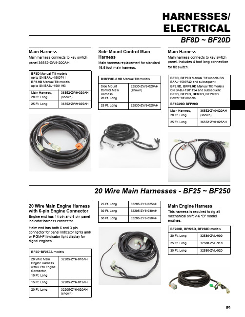
BF8D ~ BF20DMain HarnessMain harness connects to key switch panel 36552-ZW9-200AH.Side Mount Control Main HarnessMain harness replacement for standard 16.5 foot main harness.Main HarnessMain harness connects to key switch panel. Includes 4 foot long connection for tilt switch.20 Wire Main Harnesses - BF25 ~ BF25020 Wire Main Engine Harness with 6-pin Engine ConnectorEngine end has 14 pin and 6 pin panel indicator harness connector.Helm end has both 6 and 3 pinconnector for panel indicator lights and/or PGM-FI indicator light display for digital engines.Main Engine HarnessThis harness is required to rig all mechanical shift V-6 “D” model engines.BF8D Manual Tilt models up to SN BAAJ-1500741BF9.9D Manual Tilt models up to SN BABJ-1501193Main Harness, 20 Ft. Long 36552-ZW9-020AH (shown)25 Ft. Long36552-ZW9-025AHB/BFP8D-9.9D Manual Tilt models Side Mount Control Main Harness,20 Ft. Long 32530-ZW9-020AH (shown)25 Ft. Long32530-ZW9-025AHBF8D, BFP8D Manual Tilt models SN BAAJ-1500742 and subsequentBF9.9D, BFP9.9D Manual Tilt models SN BABJ-1501194 and subsequent BF8D, BFP8D, BF9.9D, BFP9.9D Power Tilt models; BF15/20D BFP20D Main Harness,20 Ft. Long 36552-ZY0-020AH (shown)25 Ft. Long36552-ZY0-025AHBF25~BF250A models 20 Wire Main Engine Harness with 6-Pin Engine Connector,10 Ft. Long 32205-ZY6-010AH15 Ft. Long 32205-ZY6-015AH 20 Ft. Long32205-ZY6-020AH (shown)25 Ft. Long 32205-ZY6-025AH 30 Ft. Long 32205-ZY6-030AH 50 Ft. Long32205-ZY6-050AHBF200D, BF225D, BF250D models 20 Ft. Long 32580-ZVL-90025 Ft. Long 32580-ZVL-91030 Ft. Long32580-ZVL-920ExtensionsMain Harness Extension7 Foot Long : Connects at engine end.Main Harness Extension7 Foot Long : Connects at engine end.17 Wire Extension7 Foot Long : Connects at helm end.Power Harness Cable25 Feet Long : When extended battery cables are in use.BF8D, BFP8D, BF9.9D, BFP9.9D, BF15D, BF20D Manual Tilt models 7 Ft. Long Main Harness Extension32570-ZW9-000AHBF8D, BFP8D, BF9.9D, BFP9.9DBF15D, BF20D Power Tilt models7 Ft. Long Main Harness Extension32570-ZY1-000AHBF25~BF250D 7 Ft. Long 17 Wire Extension08M66-ZW7-230AHBF200D, BF225D, BF250D 25 Ft. Long Power Harness Cable31576-ZVL-000No image available3 Wire PGM-FI Harnesses3 Wire PGM-FI Panel Harness Extension3 Foot Long : Connects at helm end.3 Wire PGM-FI Panel Harness Extension30 Foot Long : Harness connects PGM-FI panel to engine. Use with 30 foot long 14 wire main harness for 30 foot runs.3 Wire PGM-FI Panel Harness Extension7 Foot Long : Connects at helm end.3 Wire PGM-FI Panel Harness Extension16.5 Foot Long : Original equipment harness connects PGM-FI panel to engine.BF115~BF225A 3 Ft. Long, 3 Wire PGM-FI Panel Harness Extension08M66-ZW7-240AHBF115~BF225A 30 Ft. Long, 3Wire PGM-FI Panel Harness Extension08M66-ZW7-220AHBF115~BF225A 7 Ft. Long, 3 Wire PGM-FI Panel Harness Extension08M66-ZW7-210AHBF115~BF225A 16.5 Ft. Long, 3Wire PGM-FI Panel Harness Extension32185-ZW5-0009 Wire PGM-FI HarnessesDigital Gauge Ready - 9 Wire Panel Indicator HarnessEngine end has a 6 pin connector.Helm end has both 6 and 3 pinconnector for panel indicator lights on key switch panel and/or PGM-FIindicator light display for digital gauges. Includes sealing caps provided for unused connector.Connects to digital gauge harnesses 06326-ZY3-802AH and 32540-ZY3-800AHR when using a 17 wire main harness.9 Wire Panel Indicator Harness Extension4 foot extension harness to extend the 6 pin and 3 pin connectors at the helm end of the following harnesses: •20 wire main engine harness •23 wire universal main engine harness•9 wire panel indicator harnessBF40D~BF250A Digital Gauge Ready - 9 WirePanel Indicator Harness,20 Ft. Long 32185-ZY6-020AH (shown)25 Ft. Long32185-ZY6-025AHBF40D~BF250A 9 Wire Panel Indicator Harness Extension,4 Ft. Long32185-ZY6-004AHAdapter HarnessesTachometer Adapter HarnessJumper harness from charge coil to tach sending wire.6 Pin to 3 Pin Panel Indicator Harness AdapterAllows old style 17 wire main engine harness to connect to 2005 and subsequent year model BF115 thru BF225 with 6 pin panel indicator connector at engine end.3 Pin to 6 Pin Panel Indicator Harness AdapterAllows new 20 wire main engine harness to connect to 2005 and subsequent year model BF115 thru BF225 with 6 pin panel indicator connector at harness end.“D” Series Adapter Harness“D” model V-6 engine adapter harness for boats that already have a two-connector harness installed.BF8~BF50 Tiller Tachometer Adapter Harness32197-ZH8-003BF40D~225 2005 model year andsubsequent BF250A 6 Pin to 3 PinPanel Indicator Harness Adapter32197-ZY6-002AHBF115~225 2005 model year and subsequent, BF250A 3 Pin to 6 Pin Panel Indicator Harness Adapter32198-ZY6-002AHBF200D, BF225D,BF250D 6 ft.32590-ZVL-90010 ft.32590-ZVL-910BF200D ~ BF250D iST ® CablesTrunk CableEngine Drop Cable - Single EngineEngine drop cable for single engine configuration.Engine Drop Cable - Multi-EngineEngine drop cable for multi-engine configurations.Branch Cable AssemblyRequired for multi engine installations .12V Load Signal ConnectorProvides a key-on signal to devices such as trim tabs, power steering, and other devices that require 12V.Not to be used for accessory power supply; wake up signal only.BF200D~BF250D iST Engines 18 ft.32580-ZVL-60024 ft.32580-ZVL-70030 ft.32580-ZVL-800BF200D~BF250D iST Engines 6 ft.32590-ZVL-00016 ft.32590-ZVL-81020 ft.32590-ZVL-82025 ft.32590-ZVL-83030 ft.32590-ZVL-840BF200D~BF250D iST Engines 6 ft.32590-ZVL-60010 ft.32590-ZVL-70014 ft.32590-ZVL-800BF200D~BF250D iST Engines Branch Cable32540-ZVL-600BF200D~BF250D iST Engines Signal Connector32531-ZVL-000Engine Outlet GrommetEngine Outlet GrommetEngine Outlet GrommetAllows waterproof connection of hard wall conduit or covering material.Engine Outlet GrommetAccommodates 17 wire main harness for BF115/130. Grommet extends out approximately 2 inches and allows waterproof connection of cable and harness covering material.Engine Outlet GrommetEngine Outlet Grommet (Mechanical)Engine Outlet Grommet(iST)BF75DK, BF90DK, BF100A Engine Outlet Grommet40105-ZY9-000BF75A, BF90A Engine Outlet Grommet32168-ZW1-000AHBF115A, BF130A Engine Outlet Grommet40106-ZW7-U00Engine Outlet Grommet,BF200/225A2~A540105-ZY3-010(shown)BF200/225A6~K040105-ZY3-A11BF200/225K1~K3, BF250A40105-ZY3-C01BF200D, BF225D, BF250D Engine Outlet Grommet40105-ZVL-900BF200D, BF225D, BF250D iST Engine Outlet Grommet40105-ZVL-000No Image AvailableRigging Tube AdaptersSplit Rigging Tube KitFive piece kit allows easy rigging of engine harnesses, control cables, fuel line. Replaces rubber grommet. Note: Solid wall tubing must be used with this kit.Split Rigging Tube Service KitThis kit consists of 4 sheets of the rubber material used with the split rigging tube kit. When re-rigging an engine with the split rigging tube kit, you will need to re-apply two sheets per engine–this kit accommodates a twin engine installation.Threaded Rigging Tube AdapterThis adapter allows the use of a solid rigging tube from the outboard engine to the hull of the boat.Threaded Rigging Tube AdapterThis adapter allows the use of a solid rigging tube from the outboard engine to the hull of the boat. All rigging tubes are not the same diameter. The tube inside diameter must be 1-7/8 inches.BF200A, BF225A, BF250A Split Rigging Tube Kit40105-ZY3-010AHBF200A, BF225A Split Rigging Tube ServiceKit40106-ZY3-010BF115D, BF135A, BF150AThreaded Rigging Tube Adapter40105-ZY6-010AHBF200A, BF225A, BF250A ThreadedRigging Tube Adapter40200-ZY3-020AH。
得捷电子 保温热交换器系列说明书

H EAT R ECOVERY F OR P ROCESS E FFICIENCY. E ven when fuel prices are low, companies in energy-intensive industries can see a benefit and enjoy a relatively short payback from utilizing some type of heat recovery system to improve the efficiency of their process. A uthored by Jessica Irons, Product Marketing Manager,Honeywell Thermal SolutionsTABLE OF CONTENTS 3 Abstract 4 Introduction 5 Basic Heat Recovery Methods for Process Heating 6 Heat Exchanger Types 7 Air-to-Air Heat Exchanger Selection Guide 8 F low Configurations for Air-to-Air HeatExchangers 9 T hings to Consider Before Selecting a Heat Exchanger10 P lug In for Energy Savings11 C onclusion12 A bout the AuthorABSTRACTIn many industrial applications, the waste heat in the form of heated air or steam is unused and allowed to escape up the stack. Implementing ways to capture waste heat can improve efficiency while helping processors save money. This article talks about how installing an effective air-to-air heat exchanger helps you recover this resource and increase energy efficiency of the plant.INTRODUCTIONWith an ever-increasing focus on energy efficiency and improving system performance, industrial processors are looking for ways to achieve these goals while reducing costs and material usage wherever possible.One proven way to increase energy efficiency and reduce fuel usage is to recover heat from industrial processes. Waste heat is unused heat given off by a process or equipment in the form of thermal energy -- that is, heat which is not being captured to heat some other product or process. Waste heat can be thought of as free energy. Though, of course, there is a cost to create it, waste heat is thermal energy you would otherwise let escape up the stack rather than using in your process. Implementing ways to capture waste heat can improve efficiency while helping processorssave money.Even when fuel prices are low, companies in energy-intensive industries can see a benefit and enjoy a relatively short payback from utilizing some type of heat recovery system to improve the efficiency of their process.1Plate Type Heat ExchangerThe exchanger uses the properties of thermodynamics and fluid mechanics to heator cool one medium to the desired temperature. A basic schematic of a process oven with heat recovery demonstrates the general process (figure 1).In many industrial applications, the waste heat will be in the form of a gas. Usually, itis heated air or steam. Thus, air-to-air heat exchangers are quite common in industrial applications. (Air-to- air heat exchangers are also found in many commercial buildings, HVAC systems, and even in some modern houses.)Air-to-air heat exchangers are used for many industrial applications:• H eat recovery for preheating the same process or other processes• C ombustion air pre-heating• O ven/furnace makeup air preheating• F ume preheat on catalytic/recuperative thermal oxidizers• S econdary heat recovery on regenerative oxidizers• H eat exchange and recovery for Volatile Organic Compound (VOC) concentrators One of the benefits of using a heat exchanger to recover waste heat is that they are designed and built such that the air containing the waste heat does not come into contact with the new, clean process air. This is particularly helpful when the exhaust has excess dirt or dust particles that could contaminate products or equipment elsewhere in the process.2BASIC HEAT RECOVERY METHODS FOR PROCESS HEATINGThe most straightforward method of capturing waste heat energy is a heat exchanger. Aheat exchanger is a device used to transfer heat from one medium — typically air, gas, or fluid — to another medium. The two media are separated by solid wall, a plate or tube.Figure 1. The most straightforward method of capturing waste heat energy is through the use of aheat exchanger. Shown here is a basic schematic of a process oven with heat recovery.3HEAT EXCHANGER TYPES The most common types of air-to-air heat exchangers are tubular type and plate type.Tubular: Tubular type heat exchangers use a series of tubes to allow the exchange of heat between the two media. The waste stream passes over the tubes, pre-heating the process stream flowing inside the tubes. Depending on the needs of the application, the configuration can be reversed such that the waste stream flows through the tubes and the process air flows over the tubes. For ease of cleaning, make sure the dirty stream flows through the inside of the tubes.Tubular-type heat exchangers are not as effective at transferring heat as plate types. However, they can withstand higher temperatures, can be made out of exotic materials, and take a lower pressure drop. They tend to weigh more than plate types, and improper install and consistent high-low temperature cycling can promote cracking of the tubes. Additionally, due to the reduced effectiveness of the tubular type, the exchangers end up being big and long, taking up additional space in the plant. The size can also increase the stress on the tube end welds.Plate: Plate-type heat exchangers use a series of nested plates to allow the exchange of heat between the two media without the two air streams coming into contact with each other.Dimple and Sinusoidal: The two most common plate styles are dimple plate and wave/sinusoidal plate. Dimple-plate types are better for process steams that are dirty and could potentially cause clogging between the plates. Sinusoidal- or wave-plate types offer the best heat transfer effectiveness. The basic premise behind the plate technology is to have a pattern in the plate that causes a lot of turbulence in the air asit flows around the plates, which increases heat transfer. (Figures 4a and 4b)Figure 2: Tubular-type heat exchangers use a series of tubes to allow exchange of heatbetween the two media.Figure 3: Plate-type heat exchangers use a series of nested plates to allow the exchange of heat between the two media without the two airstreams coming into contact with each other.Figure 4a: Example of Dimple Plate Heat ExchangerFigure 4b: Sinusoidal or wave-plate exchangers offer the best heat transfer effectiveness.4AIR-TO-AIR HEAT EXCHANGERSELECTION GUIDETubularSinusoidal Plate Dimple Plate Table 1: When considering a heat exchanger design, plate or tube spacing is a key factor in heat exchanger performance.5FLOW CONFIGURATIONS FOR AIR-TO-AIR HEAT EXCHANGERS Another important consideration when selecting a heat exchanger is what type of flow configuration makes most sense for the process. Given that each exchanger will carry two flowing media, transferring heat between them, four flow configurations are available for plate-type heat exchangers.IU —One vertical stream and one in a “U” patternLL — Both flows in an “L ” patternIZ — One vertical stream and one in a “Z” patternLU — One “L ” flow and one in a “U” flowEach configuration has its pros and cons. One thing to be aware of when selecting a flow configuration is any potential “ineffective zone.” In those areas, hot and cold spots are created by the airflow pattern, and limited heat exchange is taking place.In any given flow configuration, there are two things going on:1. S eparate ineffective zones exist for each side (pass) of the exchanger. Certain ineffective zones are created in each of the flow patterns except for the (I) pattern.2. T he ineffective zones can change location depending on flow rate. For example, in a “U” flow pattern, at low flow rates, the ineffective zone is on the far side of the exchanger. With high flow rates, the ineffective zone is on the near side of the exchanger.For air-to-air heat recovery in waste heat applications, a vertical flow pattern (IU) is best the configuration for heat transfer. It heats the process air most evenly and has fewer ineffective zones. It also is easiest to clean for applications such as food, where washdown is required. Water or cleaning solutions can literally be pumped into the top of the exchanger, and the solution will flow down in the direction of gravity without concern of getting caught in the exchanger.The LL Flow pattern where each stream flows in an “L ” shape — is the most common for heat recovery applications. It transfers heat less effectively and the air to be heated will be a little hotter on the far side of the exchanger. The ineffective zones are on either side of the L flows, creating two ineffective zones instead of just one.The IZ flow pattern - one vertical pattern and one in a Z pattern - is less common. It can be useful to help fit in an existing space. It also creates two ineffective zones on either side of the exchanger.The LU flow pattern — one in an L pattern and one in a U pattern -- also has two ineffective zones. Depending on the orientation of the heat exchanger, debris orcondensation can collect in the bottom.Figure 5: A vertical flow pattern (IU) is the best configuration for heat transfer. It is the most effective, heats the process air most evenly, and has fewer ineffective zones. The potential ineffective zone is shown in yellow inthis diagram.Figure 6: Flow configurations and associated potential ineffective heat transfer zones.6 THINGS TO CONSIDERBEFORE SELECTING AHEAT EXCHANGERWhen selecting an appropriate heatexchanger for your process, consider thingssuch as durability, exchanger life expectancy,ease of installation, maintenance required,ease of cleaning, and space available toinstall the exchanger.Dimple-plate type heat exchangers tend to be the most durable of the three typesbecause thick plates are used, and they are designed to withstand dirty processair streams. Tubular heat exchangers have a shorter life expectancy because theexpansion and contraction of the tube material -- due to temperature changes overtime -- makes the tubes more susceptible to wear and breakage. Sinusoidal- plate-type exchangers tend to be more fragile, with thinner plates. They must be monitoredclosely to ensure they do not overheat. Overheating could cause failure of the plate,and lose heat transfer effectiveness, and compromising cleanliness of the processair stream.It is also important to ensure that the filter for the air intake to the process andexchanger is replaced on a regular basis. Excess debris in the filter could cause airflowto the exchanger to be compromised, reducing the effectiveness and performance ofthe unit. Additionally, if the filter is dirty or not properly installed, dirt and dust couldmake its way into the equipment and cause plate failures.Lastly, it is important to remember that when considering a heat exchanger design,plate or tube spacing is a key factor in heat exchanger performance. (Table 1) Tubesor plates packed more closely can offer more heat transfer surface area in a smallerfootprint. The tradeoff is they are more difficult to clean, and you may experience ahigher pressure drop across the exchanger. Tubes or plates packed less closely are lesseffective but easier to clean. The tradeoff is you may have a smaller pressure drop acrossthe exchanger.7PLUG IN FOR ENERGY SAVINGSAnother type of tubular heat exchanger is known as a plug-in recuperator. As the name implies, it is plugged into the exhaust stream, paired with an eductor, and uses waste heat to preheat the combustion air. Table 2 shows the potential fuel savings that can be achieved when using preheated combustion air (PCA) from any heat exchanger like the plug in recuperators. This data is calculated based on the difference of available heat with and without a recuperator. Keep in mind this data is for preheatedcombustion air only, not for process air.FUEL SAVINGS ACHIEVED USING A PLUG-IN RECUPERATOR WHOLE SYSTEM THINKINGWhen a heat exchanger such as a sinusoidal plate type is paired with a complete system — which includes a burner, controls, recirculation fans, and all system components — it can be inserted into a process where it is critical to have a supply of clean, indirectly heated process air.Recirculating heaters are designed to prevent the products of combustion from getting into the process airstream. This is especially important in applications such as food and beverage, pharmaceuticals, and automotive paint finishing.Figure 8 shows a schematic of a burner/heater system.Figure 9 shows an Indirect Air Heater, which combines an ultra-low NOx burner with asinusoidal plate heat exchanger for low emissions, highly effective process air heating.Figure 7: Types of plug-in recuperators Figure 9: An indirect air heater, which combines an ultra-low NOx burner with a sinusoidal-plate heat exchanger can provide low emissions andeffective process air heating.Figure 8: Process Flow Diagram for heater systemCONCLUSIONEnergy equals money, and waste heat is essentially free energy. If you are looking for ways to improve the overall efficiency of your process, improve fuel savings and, ultimately, save money, consider installing a heat exchanger to recover process heat in almost any application.ABOUTTHE AUTHORJessica Irons, HoneywellJessica Irons is a Product Marketing Manager at Honeywell Thermal Solutions, Rockford, IL and can be reached at (815) 877-3031. The Honeywell Thermal Solutions family of products includes Honeywell Combustion Safety, Honeywell Combustion Service, Eclipse, Exothermics, Hauck, Kromschröder and Maxon. To learn more, visit .For More InformationThe Honeywell Thermal Solutions family ofproducts includes Honeywell CombustionControls, Honeywell Combustion Safety,Honeywell Combustion Service, Eclipse,Exothermics, Hauck, Kromschröder andMaxon. To learn more about our products,visit orcontact your Honeywell Sales Engineer.Honeywell Process Solutions:1250 West Sam Houston ParkwaySouth Houston, TX 77042Honeywell House, Skimped Hill LaneBracknell, Berkshire, England RG12 1EB UKBuilding #1, 555 Huanke Road,Zhangjiang Hi-Tech Industrial Park,WP-20-04-ENG | 02/20。
F1220D_QSG_CN说明书

EUROLIVEF1220DBi-Amped 250-Watt Monitor Speaker System with 12" Woofer, 3" Tweeter and Feedback FilterV 6.0带有此标志的终端设备具有强大的电流, 存在触电危险。
仅限使用带有 ¼'' TS 或扭锁式插头的高品质专业扬声器线。
所有的安装或调整均须由合格的专业人员进行。
此标志提醒您, 产品内存在未绝缘的危险电压, 有触电危险。
此标志提醒您查阅所附的重要的使用及维修说明。
请阅读有关手册。
小心为避免触电危险, 请勿打开机顶盖 (或背面挡板)。
设备内没有可供用户维修使用的部件。
请将维修事项交由合格的专业人员进行。
小心为避免着火或触电危险, 请勿将此设备置于雨淋或潮湿中。
此设备也不可受液体滴溅, 盛有液体的容器也不可置于其上, 如花瓶等。
小心维修说明仅是给合格的专业维修人员使用的。
为避免触电危险, 除了使用说明书提到的以外, 请勿进行任何其它维修。
所有维修均须由合格的专业人员进行。
1. 请阅读这些说明。
2. 请妥善保存这些说明。
3. 请注意所有的警示。
4. 请遵守所有的说明。
5. 请勿在靠近水的地方使用本产品。
6. 请用干布清洁本产品。
7.请勿堵塞通风口。
安装本产品时请遵照厂家的说明。
8. 请勿将本产品安装在热源附近,如 暖 气 片, 炉子或其它产生热量的设备 ( 包 括功放器)。
9. 请勿移除极性插头或接地插头的安全装置。
接地插头是由两个插塞接点及一个接地头构成。
若随货提供的插头不适合您的插座, 请找电工更换一个合适的插座。
10. 妥善保护电源线, 使其不被践踏或刺破, 尤其注意电源插头、多用途插座及设备连接处。
11. 请只使用厂家指定的附属设备和配 件。
12. 请只使用厂家指定的或随货销售的手推车, 架子, 三 角架, 支架和桌子。
若使用手推车来搬运设备, 请注意安全放置设备, 以 避免手推车和设备倾倒而受伤。
IRGP4086PBF;中文规格书,Datasheet资料

tf
Fall time
td(on)
Turn-On delay time
tr
Rise time
— 65 —
— 30 —
IC = 25A, VCC = 196V
— 33 — ns RG = 10Ω, L=200μH, LS= 200nH
td(off) tf tst
EPULSE
Turn-Off delay time Fall time Shoot Through Blocking Time
2
/
240
VGE = 18V
200
VGE = 15V
VGE = 12V
160
VGE = 10V VGE = 8.0V
120
VGE = 6.0V
ICE (A)
80
40
0
0
4
8
12
16
VCE (V)
Fig 1. Typical Output Characteristics @ 25°C
––– 29 ––– ––– 65 ––– ––– 22 ––– — 36 — — 31 — — 112 —
S VCE = 25V, ICE = 25A nC VCE = 200V, IC = 25A, VGE = 15Ve
IC = 25A, VCC = 196V ns RG = 10Ω, L=200μH, LS= 200nH
Parameter Thermal Resistance Junction-to-Case-(each IGBT) d Case-to-Sink (flat, greased surface) Junction-to-Ambient (typical socket mount) d Weight
华氏12012线性4-20mA输出温度传感器说明书

To Order (Specify Model Number)
Model No.
Price Description
Applications
OS1611(*)-(**) OS1711(*)-(**) OS1811(*)-(**)
$ 930 1125 1850
Remote IR sensing head and electronics
Shown smaller than actual size.
OS1700 Series sensor with integral electronics.
ߜ Linear 4 to 20 mA Output
ߜ Simple 2-Wire Installation
ߜ 10 to 40 Vdc Power Operation
ߜ 3 Models to Choose From
ߜ 6 Infrared Spectral Responses
OS1800 Series sensor with integral electronics/display.
OS1600 Series OEM style sensor and remote electronics.
J-95
RUGGED!
INDUSTRIAL!
Rear view showing sensor.
J
OS1811-112-S, $1600, shown actual size.
signal allows the sensor to be interfaced with a variety of remote devices: indicators, controllers, recorders, and/or computers, etc.
Schneider Electric TeSys F 联接式接触器数据册说明书

T h e i n f o r m a t i o n p r o v i d e d i n t h i s d o c u m e n t a t i o n c o n t a i n s g e n e r a l d e s c r i p t i o n s a n d /o r t e c h n i c a l c h a r a c t e r i s t i c s o f t h e p e r f o r m a n c e o f t h e p r o d u c t s c o n t a i n e d h e r e i n .T h i s d o c u m e n t a t i o n i s n o t i n t e n d e d a s a s u b s t i t u t e f o r a n d i s n o t t o b e u s e d f o r d e t e r m i n i n g s u i t a b i l i t y o r r e l i a b i l i t y o f t h e s e p r o d u c t s f o r s p e c i f i c u s e r a p p l i c a t i o n s .I t i s t h e d u t y o f a n y s u c h u s e r o r i n t e g r a t o r t o p e r f o r m t h e a p p r o p r i a t e a n d c o m p l e t e r i s k a n a l y s i s , e v a l u a t i o n a n d t e s t i n g o f t h e p r o d u c t s w i t h r e s p e c t t o t h e r e l e v a n t s p e c i f i c a p p l i c a t i o n o r u s e t h e r e o f .N e i t h e r S c h n e i d e r E l e c t r i c I n d u s t r i e s S A S n o r a n y o f i t s a f f i l i a t e s o r s u b s i d i a r i e s s h a l l b e r e s p o n s i b l e o r l i a b l e f o r m i s u s e o f t h e i n f o r m a t i o n c o n t a i n e d h e r e i n .Product data sheetCharacteristicsLC1F400P7TeSys F contactor - 3P (3 NO) - AC-3 - <= 440V 400 A - coil 230 V ACMainRange TeSys Product name TeSys F Product or component typeContactor Device short name LC1F Contactor application Motor control Resistive load Utilisation categoryAC-1AC-3AC-4Poles description 3PPower pole contact composition3 NO[Ue] rated operational voltage<= 1000 V AC 50/60 Hz <= 460 V DC[Ie] rated operational current500 A (at <40 °C) at <= 440 V AC AC-1400 A (at <55 °C) at <= 440 V AC AC-3Motor power kW75 KW at 400 V AC 50/60 Hz (AC-4)200 KW at 380...400 V AC 50/60 Hz (AC-3)220 KW at 415 V AC 50/60 Hz (AC-3)250 KW at 440 V AC 50/60 Hz (AC-3)257 KW at 500 V AC 50/60 Hz (AC-3)280 KW at 660...690 V AC 50/60 Hz (AC-3)185 KW at 1000 V AC 50/60 Hz (AC-3)110 kW at 220...230 V AC 50/60 Hz (AC-3)[Uc] control circuit voltage230 V AC 40...400 HzComplementary[Uimp] rated impulse withstand voltage 8 kV Overvoltage categoryIII[Ith] conventional free air thermal current 500 A (at 40 °C)Rated breaking capacity3200 A conforming to IEC 60947-4-1[Icw] rated short-time withstand current3600 A 40 °C - 10 s 2400 A 40 °C - 30 s 1700 A 40 °C - 1 min 1200 A 40 °C - 3 min 1000 A 40 °C - 10 min Associated fuse rating 400 A aM at <= 440 V 500 A gG at <= 440 V Average impedance 0.26 mOhm - Ith 500 A 50 Hz[Ui] rated insulation voltage 1000 V conforming to IEC 60947-4-11500 V conforming to VDE 0110 group C Power dissipation per pole 65 W AC-142 W AC-3Mounting support PlateStandardsEN 60947-1EN 60947-4-1IEC 60947-1IEC 60947-4-1JIS C8201-4-1Product certifications ABSCSAULBVDNVRMRoSLROS (Lloyds register of shipping)CBRINAConnections - terminals Control circuit: screw clamp terminals 1 cable(s) 1…4 mm²flexible without cableendControl circuit: screw clamp terminals 2 cable(s) 1…4 mm²flexible without cableendControl circuit: screw clamp terminals 1 cable(s) 1…4 mm²flexible with cable endControl circuit: screw clamp terminals 2 cable(s) 1…2.5 mm²flexible with cableendControl circuit: screw clamp terminals 1 cable(s) 1…4 mm²solid without cable endControl circuit: screw clamp terminals 2 cable(s) 1…4 mm²solid without cable endPower circuit: bar 2 cable(s) - busbar cross section: 30 x 5 mmPower circuit: lugs-ring terminals 2 cable(s) 150 mm²Power circuit: bolted connectionTightening torque Control circuit: 1.2 N.mPower circuit: 35 N.mControl circuit voltage limits Operational: 0.85...1.1 Uc 40...400 Hz (at 55 °C)Drop-out: 0.3...0.5 Uc 40...400 Hz (at 55 °C)Inrush power in VA1075 VA 40...400 Hz cos phi 0.9 (at 20 °C)Hold-in power consumption in VA15 VA 40...400 Hz cos phi 0.9 (at 20 °C)Heat dissipation14 WOperating time40...65 ms closing100...170 ms openingMechanical durability10 McyclesMaximum operating rate2400 cyc/h 55 °CCompatibility code LC1FMotor power range110…220 KW at 480…500 V 3 phases110…220 KW at 380…440 V 3 phases110…220 KW at 200…240 V 3 phases250…500 kW at 480…500 V 3 phasesMotor starter type Direct on-line contactorContactor coil voltage230 V AC standardEnvironmentIP degree of protection IP20 front face with shrouds conforming to IEC 60529IP20 front face with shrouds conforming to VDE 0106Protective treatment THAmbient air temperature for operation-5…55 °CAmbient air temperature for storage-60…80 °C-40…70 °CPermissible ambient air temperature around thedeviceHeight206 mmWidth213 mmDepth219 mmNet weight9.1 kgPacking UnitsPackage 1 Weight9.176 kgPackage 1 Height 2.600 dmPackage 1 width 2.500 dmPackage 1 Length 3.200 dmOffer SustainabilitySustainable offer status Green Premium productEU RoHS Directive Compliant EU RoHS DeclarationMercury free YesRoHS exemption information YesChina RoHS Regulation China RoHS DeclarationEnvironmental Disclosure Product Environmental ProfileCircularity Profile End Of Life InformationWEEE The product must be disposed on European Union markets following specificwaste collection and never end up in rubbish binsContractual warrantyWarranty18 monthsProduct data sheetLC1F400P7Dimensions DrawingsDimensions and DrawingsLC1 F400 and F500(1)Power terminal protection shroudNOTE: X1 (mm) = Minimum electrical clearance according to operating voltage and breaking capacity.TeSys F reversing contactors and changeover contactor pairs Vertically mountedNOTE: For customer assembly, with mechanical interlock (MI) LA9 F, fixing recommended on AM1 EC uprights (please consult your Regional Sales Office). 2 x LC1 identical or different ratings (LC1 F115 to F630 and F800).Assembly A(1)Mechanical interlock shaft.(2)For assembly of contactors of different ratings only.(3) 4 x Ø6.5 for LC1 F115 to F225.Assembly A(7) - Mechanical interlock reference(4) 4 x Ø6.5 for LC1 F265.(5)Mechanical interlock guide bracket. Assembly B(7) - Mechanical interlock referenceAssembly C(6) 4 x Ø8.5 for LC1 F400, F500 or 4 x Ø10.5 for LC1 F630 and F800.(7)Only 3P for F800.(8)In this case, G4 is greater than G5.Assembly C(7)Connections and SchemaConnections and Schema2, 3, and 4-pole ContactorsLC1 F115 to F630, F1250(coil LX1 F )LC1 F115 to F630 , F1250 (coil LX4 F ) LC1 F115 to F265 (coil LX9 F )LC1 F800 (coil LX8 F / )。
分立元件库元件名称及中英对照

部分分立元件库元件名称及中英对照AND ------------------------------------与门ANTENNA --------------------------------天线BA TTERY --------------------------------直流电源BELL -----------------------------------铃,钟BVC ------------------------------------同轴电缆接插件BRIDEG 1 -------------------------------整流桥(二极管) BRIDEG 2 -------------------------------整流桥(集成块) BUFFER--------------------------------- 缓冲器BUZZER----------------------------------蜂鸣器CAP ------------------------------------电容CAPACITOR ------------------------------电容CAPACITOR POL --------------------------有极性电容CAPV AR ---------------------------------可调电容CIRCUIT BREAKER ------------------------熔断丝COAX -----------------------------------同轴电缆CON ------------------------------------插口CRYSTAL --------------------------------晶体整荡器DB --------------------------------------并行插口DIODE ---------------------------------二极管DIODE SCHOTTKY ------------------------稳压二极管DIODE V ARACTOR ------------------------变容二极管DPY_3-SEG---------------------------- 3段LEDDPY_7-SEG---------------------------- 7段LEDDPY_7-SEG_DP -------------------------7段LED(带小数点) ELECTRO ------------------------------电解电容FUSE ----------------------------------熔断器INDUCTOR -----------------------------电感INDUCTOR IRON -------------------------带铁芯电感INDUCTOR3 -----------------------------可调电感JFET N -------------------------------N沟道场效应管JFET P --------------------------------P沟道场效应管LAMP ----------------------------------灯泡LAMP NEDN -----------------------------起辉器LED -----------------------------------发光二极管METER ---------------------------------仪表MICROPHONE ----------------------------麦克风MOSFET --------------------------------MOS管MOTOR AC -----------------------------交流电机MOTOR SERVO --------------------------伺服电机NAND ----------------------------------与非门NOR ----------------------------------或非门NOT -----------------------------------非门NPN -----------------------------------NPN----三极管NPN-PHOTO ------------------------------感光三极管OPAMP ----------------------------------运放OR ------------------------------------或门PHOTO ---------------------------------感光二极管PNP -----------------------------------三极管NPN DAR ----------------------------NPN三极管PNP DAR ----------------------------PNP三极管POT ----------------------------滑线变阻器PELAY-DPDT---------------------------- 双刀双掷继电器RES1.2 ----------------------------电阻RES3.4 ----------------------------可变电阻RESISTOR BRIDGE ? ----------------------------桥式电阻RESPACK ? ----------------------------电阻SCR ----------------------------晶闸管PLUG ?---------------------------- 插头PLUG AC FEMALE---------------------------- 三相交流插头SOCKET ? ----------------------------插座SOURCE CURRENT---------------------------- 电流源SOURCE VOLTAGE ----------------------------电压源SPEAKER ----------------------------扬声器SW ? ----------------------------开关SW-DPDY ?---------------------------- 双刀双掷开关SW-SPST ? ----------------------------单刀单掷开关SW-PB ----------------------------按钮THERMISTOR ----------------------------电热调节器TRANS1 ----------------------------变压器TRANS2 ----------------------------可调变压器TRIAC ?---------------------------- 三端双向可控硅TRIODE ? ----------------------------三极真空管V ARISTOR ----------------------------变阻器ZENER ? ----------------------------齐纳二极管DPY_7-SEG_D---------------------------- 数码管SW-PB ---------------------------- 开关7805----------------------------------LM7805CT。
2008年Ford自动变速箱组件目录说明书

1622008 AUTOMATIC TRANSMISSION KIT & COMPONENTS CATALOG ©2008 PARKER HANNIFIN CORP. ALL RIGHTS RESERVED3790103008397797405R55N / 5R55S / 5R55WRWD 5 SpeedA544510034070670Input ShaftO.Dr. Ring GearO.Dr. CenterShaft783Center SupportInterm. BandDirect DrumForward ClutchForward PlanetReverse BandReverse DrumLow Sprag310037179520036178530311914363912911913910896904896437490996V.B.Parts741E414494765-6370Case313321320Valve Body917747765746322420002OHK Kit004Master L/Steels Kit 006Master 030External Seal Kit1632008 AUTOMATIC TRANSMISSION KIT & COMPONENTS CATALOG ©2008 PARKER HANNIFIN CORP . ALL RIGHTS RESERVEDRWD 5 Speed5R55N / 5R55S / 5R55W862981971961560961971985879565126106146861*229964974877564285872962972104124552894Intermediate Sprag690074266Park Gear264847Park Pawl Assy995-1995-2995-3995916-2916-3919922915916-2916-3919922916263EDA181554770Ext. Hsg.781493305678Output ShaftO.Dr. Band StrutInterm. Band Strut268841Internal Linkage991-2991-3994799991-4761P-4991072410992Yoke1642008 AUTOMATIC TRANSMISSION KIT & COMPONENTS CATALOG©2008 PARKER HANNIFIN CORP. ALL RIGHTS RESERVED*Prefix Letter ‘T’ denotes Toledo-Trans Kit (TTK) Brand Transmission Kits *Prefix Letter ‘B’ denotes Bryco Brand Transmission Kits002.............T16002AP......Overhaul Kit, 5R55N (With Bonded Pistons) 1999-Up ..............................................................1..........002.............T16002GP......Overhaul Kit, 5R55S/5R55W (With Bonded Pistons) 2002-Up..................................................1..........004.............T16004AP......Master L/Steels Kit, 5R55N (With Bonded Pistons) 1999-Up ....................................................1..........004.............T16004GP......Master L/Steels Kit, 5R55S/5R55W (With Bonded Pistons) 2002-Up .......................................1..........006.............T16006AP......Master W/Steels Kit, 5R55N (With Bonded Pistons) 1999-Up...................................................1..........006.............T16006GP......Master W/Steels Kit, 5R55S/5R55W (With Bonded Pistons) 2002-Up ......................................1..........E300...........45019............Gasket, 5R55N Bottom Pan (Plastic With Silicon Bead) OE Style (With Large Holes) 1999-Up 1..........XW4Z-7A191CA D305...........45097668......Gasket, 5R55N/5R55S/5R55W Extension Housing To Case 1999-Up......................................1..........XW4Z-7086-AA A309..........41217............Gasket, 5R55N/5R55S/5R55W Pump Bolt Washer...................................................................AR ........A310..........45097667......Gasket, 5R55N/5R55S/5R55W Pump 1999-Up..........................................................................1..........XW4Z-7A136AB A311...........1988096........O-Ring, 5R55N/5R55S/5R55W Pump Cover 1999-Up ...............................................................1..........XW4Z-7A248AA A313..........1994747........O-Ring, 5R55N Inner Pump Gear 1999-Up.................................................................................1..........F77Z-7L323AA E320...........45097692......Gasket, 5R55N Valve Body Separator Plate To Case 1999-Up ................................................1..........XW4Z-7D100-BF E320...........45097738......Gasket, 5R55S/5R55W Valve Body Separator Plate To Case (Upper) 2002-Up......................1..........1L2Z-7Z490AB-1A070..........70243V..........Seal, 5R55N/5R55S/5R55W Front (No Flange) (Rubber Coated) 1999-Up ..............................1..........F77Z-7A248AA D072...........70083............Seal, 5R55N Linkage 1999-Up ..................................................................................................1..........D5AZ-7B498A D074...........70283............Seal, 5R55N Rear 2WD 2000-Up ...............................................................................................1..........XW4Z-7052AA D074...........70205............Seal, 5R55S/5R55W Rear (W/Long Boot) 2WD 2002-Up .........................................................1..........F6UZ-7052A D074...........70282............Seal, 5R55S/5R55W Extension Housing 4X4 2002-Up .............................................................1..........1L2Z-7052BA175.............6358..............Ring Kit, 5R55N/5R55S/5R55W (2 Metal 4PTFE 2 Torlon Rings) 1999-Up ...............................1..........A178..........45060279......Ring, 5R55N, 5R55W, 5R55S Pump Support (Lock-Up) 1999-Up .............................................1..........B181...........TAW- 2212....Ring, 5R55N, 5R55W, 5R55S Forward Clutch Cylinder 1999-Up .............................................2..........D184...........45060265......Ring, 5R55N, 5R55W, 5R55S Output Shaft 1999-Up.................................................................1..........A179..........30308............Ring, 5R55N, 5R55W, 5R55S Overdrive Brake Drum 1999-Up.................................................2..........B179...........30308P ..........Ring, 5R55N, 5R55W, 5R55S Direct Clutch (Center Support) 1999-Up Torlon .........................2..........119.............45082NR........Friction Module, 5R55N 1999-Up................................................................................................1..........119.............45082LR........Friction Module, 5R55S/5R55W 2002-Up...................................................................................1..........E010...........45040N ..........Filter, 5R55N (3/8” Tall Pick-up Tube) 1999-Up ..........................................................................1..........XW4Z-7A098BB E010...........F-340.............Filter, 5R55S/5R55W (2 1/4” Tall Pick-Up Tube) 2002-Up..........................................................1..........1L2Z-7A098AC5R55N / 5R55S / 5R55WRWD 5 Speed1652008 AUTOMATIC TRANSMISSION KIT & COMPONENTS CATALOG ©2008 PARKER HANNIFIN CORP. ALL RIGHTS RESERVEDB022...........45090............Band, 5R55N Overdrive/Intermediate (Hi-Energy) 1999-Up......................................................2..........XW4Z-7D034BA 030.............45030G..........Bushing Kit, 5R55N/5R55S/5R55W 1999-Up.............................................................................1..........A034..........31530............Bushing, 5R55N/5R55S/5R55W Pump Cover 1999-Up .............................................................1..........A036..........31531............Bushing, 5R55N/5R55S/5R55W Overdrive Sun Gear 1999-Up................................................1..........A036..........45039............Bushing, 5R55N/5R55S/5R55W Stator (Front) 1999-Up ...........................................................1..........A037..........31532............Bushing, 5R55N/5R55S/5R55W Stator (Rear) 1999-Up............................................................1..........A046..........31533............Bushing, 5R55N/5R55S/5R55W Coast Clutch Drum e 56036A................................................................................................................................1..........B211...........45176A..........Washer, 5R55N/5R55S/5R55W Pump To Coast Clutch Drum .063" (Plastic) 1999-Up.............1..........F7TZ-7D014TA B211...........45176B ..........Washer, 5R55N/5R55S/5R55W Pump To Coast Clutch Drum .071" (Plastic) 1999-Up.............1..........F7TZ-7D014MA B211...........45176C ..........Washer, 5R55N/5R55S/5R55W Pump To Coast Clutch Drum .075" (Plastic) 1999-Up.............1..........F7TZ-7D014NA B211...........45176D ..........Washer, 5R55N/5R55S/5R55W Pump To Coast Clutch Drum .079" (Plastic) 1999-Up.............1..........F7TZ-7D014PA B211...........45176E ..........Washer, 5R55N/5R55S/5R55W Pump To Coast Clutch Drum .083" (Plastic) 1999-Up.............1..........F7TZ-7D014RA B211...........45176F ..........Washer, 5R55N/5R55S/5R55W Pump To Coast Clutch Drum .087" (Plastic) 1999-Up.............1..........F7TZ-7D014SA C232...........45145............Washer, 5R55N/5R55S/5R55W Bearing to Forward Hub (Solid Bronze) 1999-Up .................1..........FOTZ-7D090A D263...........45077............Washer, 5R55N/5R55S/5R55W Parking Gear To Case 1999-Up ..............................................1..........D4ZZ-7B368-AD410...........D56955J ........Switch, 5R55N Neutral Safety (12 Prong Connector) 1999-Up ...............................................1..........XW4Z-7F293AA E922...........33991............Nut, 5R55N/S/W Band 1999-Up .................................................................................................2..........380850-SRWD 5 Speed5R55N / 5R55S / 5R55W。
- 1、下载文档前请自行甄别文档内容的完整性,平台不提供额外的编辑、内容补充、找答案等附加服务。
- 2、"仅部分预览"的文档,不可在线预览部分如存在完整性等问题,可反馈申请退款(可完整预览的文档不适用该条件!)。
- 3、如文档侵犯您的权益,请联系客服反馈,我们会尽快为您处理(人工客服工作时间:9:00-18:30)。
Peak Half Sine Wave Forward Current (A)
150
300
Maximum Allowable Case Temperature (°C)
VS-20ETS.. Series
125
250
At any rated load condition and with rated VRRM applied following surge. Initial TJ = 150 °C at 60 Hz 0.0083 s at 50 Hz 0.0100 s
DESCRIPTION
High voltage rectifiers optimized for very low forward voltage drop with moderate leakage. These devices are intended for use in main rectification (single or three phase bridge).
Mounting torque
Marking device
20ETS08FP 20ETS12FP
Document Number: 94339 2 For technical questions within your region: DiodesAmericas@, DiodesAsia@, DiodesEurope@ THIS DOCUMENT IS SUBJECT TO CHANGE WITHOUT NOTICE. THE PRODUCTS DESCRIBED HEREIN AND THIS DOCUMENT ARE SUBJECT TO SPECIFIC DISCLAIMERS, SET FORTH AT /doc?91000 /
Revision: 07-Nov-11
VS-20ETS..FPPbF Series, VS-20ETS..FP-M3 Series
Vishay Semiconductors
150
35
Maximum Average Forward Power Loss (W)
VS-20ETS.. Series
Maximum Allowable Case Temperature (°C)
30 25 20
125
100
180° 120° 90° 60° 30°
DC 180° 120° 90° 60° 30° RMS limit
Ø
Conduction angle
75
15 10 5 0
Ø
Conduction period VS-20ETS.. Series TJ = 150 °C 0 5 10 15 20 25
50
25
0 4 8 12 16 20 24
Average Forward Current (A)
Fig. 1 - Current Rating Characteristics
Average Forward Current (A)
Fig. 4 - Forward Power Loss Characteristics
• Fully isolated package (VINS = 2500 VRMS)
TO-220 FULL-PAK
1 Cathode 3 Anode
• UL E78996 approved • Compliant to RoHS Directive 2002/95/EC • Halogen-free according to IEC 61249-2-21 definition (-M3 only)
200
150
Ø
Conduction angle VS-20ETS.. Series TJ = 150 °C 0 4 8 12 16 20 24
100
VS-20ETS.. Series
50 0.01
0.1
1
Average Forward Current (A)
OUTPUT CURRENT IN TYPICAL APPLICATIONS
APPLICATIONS Capacitive input filter TA = 55 °C, TJ = 125 °C common heatsink of 1 °C/W SINGLE-PHASE BRIDGE 18 THREE-PHASE BRIDGE 22 UNITS A
MAJOR RATINGS AND CHARACTERISTICS
SYMBOL IF(AV) VRRM IFSM VF TJ 10 A, TJ = 25 °C CHARACTERISTICS Sinusoidal waveform Range VALUES 20 800/1200 300 1.0 - 40 to 150 UNITS A V A V °C
Revision: 07-Nov-11
VS-20ETS..FPPbF Series, VS-20ETS..FP-M3 Series
Vishay Semiconductors
ABSOLUTE MAXIMUM RATINGS
PARAMETER Maximum average forward current Maximum peak one cycle non-repetitive surge current Maximum I2t for fusing Maximum I2t for fusing SYMBOL IF(AV) IFSM I2t I2t TEST CONDITIONS TC = 51 °C, 180° conduction half sine wave 10 ms sine pulse, rated VRRM applied 10 ms sine pulse, no voltage reapplied 10 ms sine pulse, rated VRRM applied 10 ms sine pulse, no voltage reapplied t = 0.1 ms to 10 ms, no voltage reapplied VALUES 20 250 300 316 442 4420 A2s A2s A UNITS
100
Ø
Conduction period 360° 180° 120° 90° 60° 30° 0 5 10 15 20 25 30 35
200
75
150
50
100
VS-20ETS.. Series
50
25
1
10
100
Average Forward Current (A)
Fig. 2 - Current Rating Characteristics
THERMAL - MECHANICAL SPECIFICATIONS
PARAMETER Maximum junction and storage temperature range Maximum thermal resistance, junction to case Maximum thermal resistance, junction to ambient Typical thermal resistance, case to heatsink Approximate weight minimum maximum Case style TO-220 FULL-PAK (94/V0) SYMBOL TJ, TStg RthJC RthJA RthCS Mounting surface, smooth and greased DC operation TEST CONDITIONS VALUES - 40 to 150 2.8 62 0.5 2 0.07 6.0 (5.0) 12 (10) g oz. kgf · cm (lbf · in) °C/W UNITS °C
25 20 15 10 5 0
180° 120° 90° 60° 30°
300Biblioteka 250RMS limitMaximum non-repetitive surge current versus pulse train duration. Initial TJ = 150 °C No voltage reapplied Rated VRRM reapplied
Number of Equal Amplitude Half Cycle Current Pulses (N)
Fig. 5 - Maximum Non-Repetitive Surge Current
30
Peak Half Sine Wave Forward Current (A)
Maximum Average Forward Power Loss (W)
PRODUCT SUMMARY
Package IF(AV) VR VF at IF IFSM TJ max. Diode variation TO-220FP 20 A 800 V, 1200 V 1.1 V 300 A 150 °C Single die
APPLICATIONS
• Input rectification • Vishay Semiconductors switches and output rectifiers which are available in identical package outlines
VOLTAGE RATINGS
PART NUMBER VS-20ETS08FPPbF, VS-20ETS08FP-M3 VS-20ETS12FPPbF, VS-20ETS12FP-M3 VRRM, MAXIMUM PEAK REVERSE VOLTAGE V 800 1200 VRSM, MAXIMUM NON-REPETITIVE PEAK REVERSE VOLTAGE V 900 1300 IRRM AT 150 °C mA 1