abaqus中的局部坐标系2013
abaqus怎么建立随动坐标系

Abaqus怎么建立随动坐标系在ABAQUS中,随动坐标系(RCS)是一个相对于全局坐标系移动的坐标系,它可用于模拟特定位置上的应变和应力状态。
要在ABAQUS中建立随动坐标系,可以按照以下步骤进行操作:1. 定义全局坐标系在建立随动坐标系之前,我们首先需要定义全局坐标系。
全局坐标系是模型中的参考坐标系,用于定义模型的整体几何形状和方向。
在ABAQUS中,可以使用以下命令来定义全局坐标系:*Coordinate System, name=GLOBAL, Cartesian, System, 0., 0., 0.2. 定义随动坐标系在全局坐标系定义完成后,我们可以定义随动坐标系。
随动坐标系可以相对于全局坐标系进行旋转和平移,并可以指定参考点和参考方向。
以下是在ABAQUS 中定义随动坐标系的示例命令:*Coordinate System, name=RCS, RACS在这个命令中,RCS是随动坐标系的名称,RACS指定随动坐标系相对于全局坐标系旋转和平移的方式。
3. 使用随动坐标系定义完随动坐标系后,我们可以将其用于模拟中的各个部分。
以下是一些使用随动坐标系的常见场景:•在材料属性定义中,可以通过定义相对于随动坐标系的材料方向来指定材料的各向异性。
例如,可以通过如下命令定义材料的各向异性:**Material, name=Material-1*Anisotropic, type=ENGINEERING CONSTANTS, \\stiffness=ROTATED, orientation=RCS•在模型加载或边界条件中,可以使用随动坐标系来定义加载载荷的方向。
例如,可以通过如下命令定义加载载荷的方向:**CloadNODEID, component=3, load_magnitude, RC•在后处理中,可以使用随动坐标系来查看特定位置上的应变和应力状态。
例如,可以使用如下命令查看特定节点上的应变和应力:*EL PRINT, POSITION=INTEGRATION POINTS, \\COORDINATE SYSTEM=RCS通过以上步骤,在ABAQUS中建立并使用随动坐标系可以帮助我们更方便地模拟和分析特定位置上的应变和应力状态。
abaqus中的局部坐标系2013
abaqus中的局部坐标系在abaqus中,在不同的模块中使用不同的局部坐标系类型,主要有下面几种局部坐标系:1、定义节点的局部坐标系2、定义节点自由度的局部坐标系3、单元局部坐标系1.定义节点的局部坐标系(*SYSTEM)有时在一个局部坐标系中定义节点坐标是方便的,然后再转换这些坐标值到总体坐标系中。
用户可以定义一个局部节点坐标系,Abaqus将转换和旋转局部坐标值()到总体坐标系。
在input完成后立刻完成该转换,并且该转换将施加到在定义了节点坐标系后的所有输入的节点坐标上。
【1】关键字*SYSTEM关键字*SYSTEM使用规则:先定义坐标系,再使用。
先用*SYSTEM 定义局部坐标系,然后在node definition(如*NODE关键字)里面选择定义的坐标系。
返回到整体的坐标系使用*SYSTEM+ 空白的数据行。
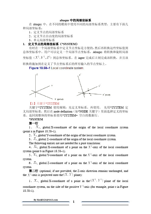
*SYSTEM第一行1、, global X-coordinate of the origin of the local coordinate system (point a in Figure 18.58–1).2、, global Y-coordinate of the origin of the local coordinate system.3、, global Z-coordinate of the origin of the local coordinate system.The following entries are not needed for a pure translation:4、, global X-coordinate of a point on the -axis of the local coordinate system (point b in Figure 18.58–1).5、, global Y-coordinate of a point on the -axis of the local coordinate system.6、, global Z-coordinate of a point on the -axis of the local coordinate system.第二行(optional; if not provided, the Z-axis direction remains unchanged, and the -axis is projected onto the plane):1、, global X-coordinate of a point in the plane of the localcoordinate system, on the side of the positive -axis (for example, point c in Figure 18.58–1).2、, global Y-coordinate of a point in the plane of the local coordinate system, on the side of the positive -axis.3、, global Z-coordinate of a point in the plane of the local coordinate system, on the side of the positive -axis.如果*SYSTEM中只给出一个点(原点),Abaqus假设用户只需要平移。
abaqus后处理参考坐标系

abaqus后处理参考坐标系Abaqus是一款强大的有限元分析软件,它可以进行各种复杂的力学分析,如静力学、动力学、热力学等。
在进行分析时,我们需要对结果进行后处理处理,其中参考坐标系是一个重要的概念。
本文将围绕“abaqus后处理参考坐标系”进行详细的讲解。
第一步:建立模型在进行abaqus后处理前,我们需要首先建立模型。
这个模型可以是通过建模软件建立的,也可以是通过abaqus的预处理模块建立的。
无论是哪种方式建立的模型,都需要经过网格划分和分析参数设定的过程。
只有这样,模型才能被提交给abaqus进行分析计算。
第二步:进行分析计算当模型经过分析参数设定后,就可以提交给abaqus进行分析计算了。
在进行计算时,abaqus会根据设定参数,按照一定的计算算法进行计算,并将计算结果输出。
第三步:查看结果当计算完成后,就需要对结果进行查看了。
在abaqus中,可以使用多种方式查看结果,如XY数据图、模态图等。
如果需要进行更深入的后处理,就需要使用abaqus的后处理功能了。
第四步:启动后处理模块在abaqus中,启动后处理模块可以通过点击主界面上的“Results”按钮,在下拉菜单中选择“Visualization”并点击“Abaqus/CAE”选项。
这样,就会进入abaqus的后处理模块了。
第五步:选择参考坐标系在进行后处理时,我们需要选择参考坐标系。
参考坐标系用于描述物体的位置和运动状态。
在abaqus中,可以选择全局坐标系,局部坐标系或者用户定义坐标系作为参考坐标系。
第六步:查看结果一旦选择了参考坐标系,就可以使用abaqus后处理模块的图像显示功能来查看结果了。
这时,我们可以对分析结果进行分析和比较,以便更好地了解结构的行为和性能。
总之,abaqus后处理参考坐标系是一个非常重要的概念。
通过本文介绍的步骤,我们可以了解到如何在abaqus中进行后处理,并选择合适的参考坐标系来查看分析结果。
abaqus中坐标系不显示
Abaqus 中坐标系不显示背景介绍Abaqus是一款广泛应用于工程领域的有限元分析软件,能够进行结构分析、热分析、流体分析等多种物理场的仿真和分析。
在使用Abaqus进行建模和仿真过程中,我们通常需要使用坐标系来指定和描述模型中的几何特性和物理行为。
然而,有时候我们会遇到坐标系不显示的问题,本文将介绍这个问题的解决方法。
问题描述在Abaqus中,我们可以通过创建坐标系来描述模型的几何特性、加载方向等信息。
通常情况下,在模型的浏览器中,可以看到一个坐标系图标用于表示整个模型的坐标系。
然而,有时候我们会发现坐标系图标不显示,仅显示一个空白图标或者没有图标。
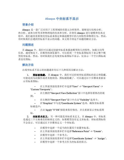
解决方法出现坐标系不显示的问题通常有以下几种原因及解决方法:1.图标被隐藏:在Abaqus中,我们可以控制坐标系图标的显示和隐藏。
可能是因为误操作或者其他原因,图标被隐藏了。
可以通过以下步骤来重新显示坐标系图标:–在主界面顶部的菜单栏中选择“View” -> “Viewport Views” -> “Custom Viewports”;–在左侧的“Viewport View Definition”窗口中选择你要修改的视图;–在右侧的“Viewport View”窗口中点击“Visibility”选项卡;–在“Graphics”中勾选“Coordinate System”选项,确保坐标系图标被选中;–点击“Apply”和“OK”按钮来保存修改,并且重新显示坐标系图标。
2.坐标系未定义:另一种可能是坐标系未定义。
在Abaqus中,坐标系是通过三个互相垂直的轴来定义的。
如果模型没有定义坐标系,坐标系图标将不会显示。
可以通过以下步骤来定义一个坐标系:–在模型中选择一个适当的位置用于放置坐标系;–在主界面顶部的菜单栏中选择“Reference Point” -> “Create”;–在模型中选择一个参考点;–在主界面顶部的菜单栏中选择“Coordinate System” -> “Assign”;–在模型中选择一个参考点作为坐标系的原点;–选择两个方向来定义坐标系的两个轴;–点击“OK”按钮来完成坐标系的定义。
abaqus中le计算方法
abaqus中le计算方法ABAQUS中的LE计算方法LE(Local Element)方法是ABAQUS中一种常用的局部坐标系下的单元应变、应力计算方法。
该方法适用于各种复杂的结构分析问题,可以更准确地描述材料的本构行为和局部应力分布情况。
本文将详细介绍ABAQUS中LE计算方法的原理和应用。
1. 原理LE方法是一种基于局部坐标系的单元应变、应力计算方法,通过将全局坐标系下的应变和应力转换到局部坐标系下进行计算。
其基本思想是将全局坐标系下的位移场和应变场转换到局部坐标系下,然后根据材料的本构关系计算出局部坐标系下的应力。
LE方法的核心是局部坐标系的选择和转换矩阵的确定。
2. 应用LE方法在ABAQUS中广泛应用于各种复杂的结构分析问题,如接触分析、断裂力学分析、材料疲劳寿命预测等。
下面以接触分析为例,介绍LE方法的具体应用步骤。
(1)建立模型:首先需要建立包含接触界面的模型,在ABAQUS中定义各个部分的几何形状、材料属性和边界条件。
(2)网格划分:将模型进行网格划分,选择合适的单元类型和单元尺寸。
(3)接触定义:定义接触界面,并设置接触类型、接触特性和接触参数。
(4)应变计算:在分析步中选择LE方法,并设置相应的计算参数,如单元类型、积分点数等。
通过LE方法计算得到局部坐标系下的应变。
(5)应力计算:根据材料的本构关系,将局部坐标系下的应变转换为应力,得到局部坐标系下的应力分布情况。
(6)结果分析:根据计算得到的结果,进行后续的应力分析、疲劳寿命预测等。
3. 注意事项在使用ABAQUS中的LE方法进行分析时,需要注意以下几点:(1)合理选择局部坐标系:局部坐标系的选择应符合结构的几何形状和加载条件,能够更准确地描述局部应力分布情况。
(2)适当调整单元尺寸和积分点数:单元尺寸和积分点数的选择会对计算结果的精度和计算时间产生影响。
需要根据具体问题进行合理的调整。
(3)验证计算结果:在使用LE方法进行分析后,需要对计算结果进行验证。
调整abaqus中节点坐标的方法

调整abaqus中节点坐标的⽅法Abaqus Analysis User's Manual2.1.6 Adjusting nodal coordinatesProducts: Abaqus/Standard Abaqus/Explicit Abaqus/CAEReferences*ADJUST“Defining adjust points constraints,” Section 15.15.5 of the Abaqus/CAE User's Manual OverviewNodal adjustment is used for:adjusting user-specified nodal coordinates so that the nodes lie on a given surface; andspecifying the direction along which the nodes are moved. Adjusting nodal coordinatesIn general, user-specified nodal coordinates are not modified during input file processing. However, there are some situations where mesh coordinates are known only in a generic way and it is inconvenient to determine their coordinates for their actual usage. For example, when using fasteners the specified reference node should be positioned at its projection point on the associated surface. Since that location may be known only approximately, you can use nodal adjustment to move the reference node to that location automatically. For typical usage of the nodal adjustment feature, refer to “About assembled fasteners,” Section 29.1.3 of the Abaqus/CAE User's Manual .When using this feature, the nodes are adjusted to lie on the specified surface without regard for shell thickness or shell offsets. Therefore,it is not advisable to use this feature as a way of correcting initial overclosures for contact or for tie constraints. In addition, care should be taken when choosing the nodes to be adjusted because the feature does not respect any constraints relating the relative position of the adjusted node with other nodes (e.g., rigid body definitions).Input File Usage: U se the following option to identify thenodes to be moved and the surface onto whichthe nodes are to be moved:*ADJUST, NODE SET=name, SURFACE=nameAbaqus/CAE Usage: U se the following option to move the control pointof a coupling constraint onto the coupling surface:Interaction module: Constraint Create: Coupling;Adjust control point to lie on surfaceUse the following option to move any point or pointsonto any surface:Interaction module: Constraint Create: AdjustpointsSpecifying the nodal adjustment directionA node can be moved to the surface using a normal adjustment or a directed adjustment. By default, the node is adjusted to the closest point on the specified surface along the normal to the surface. You can specify an orientation to move the node to the surface along a given direction rather than along the normal to the surface. The vector along the localZ-direction from the orientation definition is used to move the node to the surface (see “Orientations,” Section 2.2.5). If no projection can be found, the nodal coordinates are left unmodified.Input File Usage: *ADJUST, ORIENTATION=nameAbaqus/CAE Usage: T he orientation projection option is not supportedin Abaqus/CAE.。
abaqus 提取节点坐标参考资料

1、umat中如何得到单元节点的信息大家好:最近在学习umat(standard),因为程序中要用到单元节点的信息,特别是当前增量步的单元各个节点上的节点位移值和节点的整体坐标值。
据我所知,UMAT中由abqus主程序传入的STESS,COORDS等值分别是当前积分点上的信息。
请大家指点,如何得到当前增量步中积分点所在单元各个节点上信息,特别是节点位移与节点整体坐标。
有没有类似STESS,COORDS的变量可以直接传入UMAT中。
谢谢!望大家出手指点确实UMAT是在每个material point也就是高斯积分点调用,对于每一增量步,第一次迭代调用两次,以后每步迭代调用一次。
所有的操作都是针对material point来说的。
COORDS确实只是是当前积分点上的信息。
然而,我们可以应用utility subroutine GETPARTINFO来得到此时传入UMAT的节点和单元号,有了节点和单元号当然就知道他们的信息了。
2、如何输出后处理中部分节点的坐标?谢谢如果只需要一个节点的坐标的话可以通过Query来得到,但是如果要得到大量的节点坐标就不好弄了。
如何才能得到后处理中大量节点的坐标,如下图,我要得到节点150-285的坐标该如何弄啊?多谢各位!!!Re:如何输出后处理中部分节点的坐标?谢谢建立一个set然后后处理的时候用python编个程序把节点号码和坐标都读出来Re:如何输出后处理中部分节点的坐标?谢谢设置节点SET,使用如下命令:*NODE PRINT, NSET=??, FREQUENCY=??COORD到*.dat文件中查看。
Re:如何输出后处理中部分节点的坐标?谢谢*NODE PRINT, NSET=??, FREQUENCY=??COORD谢谢,上面那些该放在inp文件的什么位置阿?Re:如何输出后处理中部分节点的坐标?谢谢nset设置放到相应的part中,*node print放到完成你要的step后部。
局部坐标系建立及局部坐标系下读取坐标.

局部坐标系建立及局部坐标系下读取坐标1.局部坐标系建立:Abaqus中提供了两种方法:1.transform 2.orientation1. transformREQUIRED PARAMETERNSETOPTIONAL PARAMETERTYPE (R (DEFAULT)直角坐标系)(C 柱坐标系)(S 球坐标系) First line1.Clobal X-coordinate of point a specifying transformation.2.Clobal Y-coordinate of point a specifying transformation.3.Clobal Z-coordinate of point a specifying transformation.4.Clobal X-coordinate of point b specifying transformation.5.Clobal Y-coordinate of point b specifying transformation.6.Clobal Z-coordinate of point b specifying transformation. 其中a,b的定义是这样的:对于Ra 是X轴上一点,b是y轴上一点,原点和原先的重合对于Ca,b定义了Z轴方向。
对于Sa,b定义了Z轴方向。
(平行)说明:* transform 下面只能有一行六个参数,分别三个一组,为两个点在原坐标系中的坐标。
比如在平面直角坐标系中的变化,第一个点定义新的x轴,第二点定义新的y轴,原点不变例如:*Transform, nset=ln_piston_1_11.732050807568877/2,0.5,0,-0.5,1.732050807568877/2,0默认的转换坐标系为直角坐标系2. orientation定于材料中,参见于帮助First line:1. X-coordinate of point a.2. Y-coordinate of point a.3. Z-coordinate of point a.4. X-coordinate of point b.5. Y-coordinate of point b.6. Z-coordinate of point b.The following items, the coordinates of point c (the origin), are optional and relevant only for SYSTEM=RECTANGULAR and SYSTEM=Z RECTANGULAR. The default location of the origin, c, is the global origin.7. X-coordinate of point c.8. Y-coordinate of point c.9. Z-coordinate of point c.对直角坐标系可以定义c点,为坐标原点,a为x轴上点,b为xy平面上的点例如:*ORIENTATION, NAME=GK1,DEFINITION=COORDINATES228.907,-815.144,1222.000,389.290,-1277.958,1197.099,469.409,-1231.701,1221.980 *Solid Section, ELSET=SOLID_liner, material=MAT_HT250,ORIENT=GK12.hypermesh下创建局部坐标系以HM 8.0,创建笛卡尔坐标系为例:首先创建system的collector: system collectors然后Analysis--->System:1,选择节点以确定坐标系原点所在的位置,可以选择多个节点(n1,n2,n3,n4......)以同时创建多个相同的坐标系.2, 点orginal,随便选一个节点N1,作为坐标系的原点。
- 1、下载文档前请自行甄别文档内容的完整性,平台不提供额外的编辑、内容补充、找答案等附加服务。
- 2、"仅部分预览"的文档,不可在线预览部分如存在完整性等问题,可反馈申请退款(可完整预览的文档不适用该条件!)。
- 3、如文档侵犯您的权益,请联系客服反馈,我们会尽快为您处理(人工客服工作时间:9:00-18:30)。
abaqus中的局部坐标系在abaqus中,在不同的模块中使用不同的局部坐标系类型,主要有下面几种局部坐标系:1、定义节点的局部坐标系2、定义节点自由度的局部坐标系3、单元局部坐标系1.定义节点的局部坐标系(*SYSTEM)有时在一个局部坐标系中定义节点坐标是方便的,然后再转换这些坐标值到总体坐标系中。
用户可以定义一个局部节点坐标系,Abaqus将转换和旋转局部坐标值()到总体坐标系。
在input完成后立刻完成该转换,并且该转换将施加到在定义了节点坐标系后的所有输入的节点坐标上。
【1】关键字*SYSTEM关键字*SYSTEM使用规则:先定义坐标系,再使用。
先用*SYSTEM 定义局部坐标系,然后在node definition(如*NODE关键字)里面选择定义的坐标系。
返回到整体的坐标系使用*SYSTEM+ 空白的数据行。
*SYSTEM第一行1、, global X-coordinate of the origin of the local coordinate system (point a in Figure 18.58–1).2、, global Y-coordinate of the origin of the local coordinate system.3、, global Z-coordinate of the origin of the local coordinate system.The following entries are not needed for a pure translation:4、, global X-coordinate of a point on the -axis of the local coordinate system (point b in Figure 18.58–1).5、, global Y-coordinate of a point on the -axis of the local coordinate system.6、, global Z-coordinate of a point on the -axis of the local coordinate system.第二行(optional; if not provided, the Z-axis direction remains unchanged, and the -axis is projected onto the plane):1、, global X-coordinate of a point in the plane of the localcoordinate system, on the side of the positive -axis (for example, point c in Figure 18.58–1).2、, global Y-coordinate of a point in the plane of the local coordinate system, on the side of the positive -axis.3、, global Z-coordinate of a point in the plane of the local coordinate system, on the side of the positive -axis.如果*SYSTEM中只给出一个点(原点),Abaqus假设用户只需要平移。
如果给出了两个点,轴的方向与Z轴相同,即轴将被投影到(X,Y)平面。
为了改变起作用的当前节点坐标系,定义另外一个节点坐标系。
为了返回总体坐标系,使用*SYSTEM+ 空白的数据行。
【2】关键字*NODE*NODE, input=<定义节点坐标的文件名(可选项)>, nset=<节点集>, system=R(C,S)第一行1、Node number.2、First coordinate of the node.3、Second coordinate of the node.4、Third coordinate of the node.5、First direction cosine of the normal at the node (optional).6、Second direction cosine of the normal at the node (optional). For nodes entered in a cylindrical or spherical system, this entry is an angle given in degrees.7、Third direction cosine of the normal at the node (optional). For nodes entered in a spherical system, this entry is an angle given in degrees.当用*node 关键字定义节点坐标的时候,可选参数system指定当前起作用的节点坐标系的类型。
可选参数system指定的节点坐标系类型可以为R(直角坐标系),C(圆柱坐标系),S(球坐标系)。
对于在圆柱坐标系或球坐标系中输入节点数据中的方向余弦是角度,单位为度。
节点局部坐标系定义对于节点定义是完全局部的。
一旦节点数据被读入,这些坐标立刻被转换到直角笛卡尔坐标系。
【3】下面是定义节点局部坐标系的一些常用关键字:*SYSTEM #定义局部坐标系Data for system1 #局部坐标系的数据行*node, input=<定义节点坐标的文件名(可选项)>, nset=<节点集>, system=R(C,S)Data for node coordinates and direction cosine of normal at node #节点坐标值和方向余弦* SYSTEM #定义局部坐标系Data for system2 #局部坐标系的数据行*node, input=<输入文件名>, nset=<节点集>, system=R(C,S)Data for node number、coordinates and direction cosine of normal at node* SYSTEM #返回整体坐标*nodeData for node number、coordinates and direction cosine in global coordinate system【4】实例下面的input输入中,节点1和3在第一个节点坐标系中定义,节点4和5在第二个节点坐标系中定义,节点6和7在总体坐标系中定义。
节点8在第3个局部坐标系中定义,在局部坐标系中其坐标值(R,, , Z)为(10., 20., 5.)。
#定义局部坐标系*SYSTEM0, 0, 0, 5, 5, 5*NODE1, 0, 0, 12, 0, 0, 2(签名)3, 0, 1, 2#定义局部坐标系*SYSTEM2, 3, 4*NODE4, 0, 0, 15, 1, 4, 0#回到整体坐标系*SYSTEM*NODE6, 1, 0, 17, 0, 4, 2#定义局部坐标系*SYSTEM4, 5, 6*NODE, NSET=DISC, SYSTEM=C8, 10., 20., 5.2.定义节点自由度的局部坐标系(*TRANSFORM)在定义表面集中力、集中矩,或者边界条件和线性约束的时候,有时候不是在整体坐标系下定义的,需要在一个局部的坐标系下面定义,所以此时需要定义局部的坐标系。
若对一个节点指定了*TRANSFORM关键词定义的局部坐标系,则所有属于该节点的数据,如位移和转动自由度、集中载荷、边界条件、节点输出变量(如位移、速度、反力等)也被定义在该局部坐标系中。
在大位移分析中,此局部坐标系的方向不会随着材料的旋转而旋转。
关键字*TRANSFORM使用规则:先定义节点集合,然后对于特定的节点集合使用局部坐标系。
*TRANSFORM, NSET=<节点集>, TYPE=<坐标系类>数据行Xa, Ya, Za, Xb, Yb, Zb数据行指定了a,b两点的坐标,可以指定坐标系为直角(TYPE=R)、柱坐标系(TYPE=C)、球坐标系(TYPE=S)。
用NSET指定应用在这个局部坐标系的节点集。
关于*TRANSFORM的例子:*node, nset=set1*node, nset=set2……*TRANSFORM ,nset=set1,type=R(C,S) #R,C,R代表不同的坐标系,如图三Dataline for transform……#施加集中力*Cload #集中力作用在对应于 set1 的局部坐标系上面set1 ,1, 1000.#施加线性约束*Equation2Set1, 2, 1. #局部坐标系第二个自由度Set2, 1, -1. #整体坐标系下面第一个自由度#约束方程的数学表达:1×Set1 :2(局部坐标)-1×Set2 :1 (整体坐标)=03.定义单元局部坐标系(*ORIENTATION)This option is used to define a local coordinate system for definition of material properties; for material calculations at integration points; for element property definitions (e.g., connector elements); for output of components of stress, strain, and element section forces; and for kinematic and distributing coupling constraints.单元局部坐标系用于定义材料本构关系、用于在积分点处的材料计算、用于单元属性定义(例如connector单元)、定义单元应力应变的输出方向、单元截面力的输出方向、以及用于kinematic和distributing coupling constraints。
实体单元默认的材料方向为整体直角坐标系。
壳单元、膜单元默认的材料方向为整体直角坐标系在壳或膜单元表面的投影。
在大位移分析中,单元局部坐标系的方向会随着材料的旋转而旋转。