机械设计外文翻译(中英文)
机械设计中英文外文翻译文献
(文档含英文原文和中文翻译)中英文资料外文翻译Fundamentals Of Machinery DesignThis introductory chapter is a general survey of machinery design.First it presents the definition and major role of machinery design,the relationship between machineryand its components.Then it gives an overview of machinery design as a fundamental course and outlines a general procedure of machinery design followed by all the engineers.Finally, it lists the contents of the course and the primary goals to be achieved.1.1 The role of machinery designMachinery design is to formulate all engineering plan.Engineering in essence is to utilize the existing resources and natural law to benefit humanity.As a major segment of engineerin,machinery design involves a range of disciplines in materials,mechanics,heat,flow,control,electronics and production.Although many hightechnologies are computerized and automated,and are rapidly merged into Our daily life,machines are indispensable for various special work that is difficult or impracticable to be carried out by human.Moreover,machinery can significantly improve efficiency and quality of production,which is crucial in current competitive global market.In the modern industrialized world,the wealth and living standards of a nation are closely linked with their capabilities to design and manufacture engineering products.It can be claimed that the advancement of machinery design and manufacturing can remarkable promote the overall level of a country’s industrialization.Those nations,who do not perform well in design and manufacture fields,are not competitive in world markets.It is evident that several countries that used to be leaders in the design and manufacturing sectors until the l 960s and the1 970s had,by the l990s,slipped back and lost their leadership.On the contrary, our Country is rapidly picking up her position in manufacturing industry since the l 9 80s and is playing a more and more vital role in the global market.To accelerate such an industrializing process of our country, highly skilled design engineers having extensiveknowledge and expertise are needed.That is why the course of machinery design is of great significance for students of engineering.The course of machinery design is considerable different from those background subjects in science and mathematics.For many students,it is perhaps one of their basic professional engineering courses concerned with obtaining solutions to practical problem s.Definitely these solutions must clearly represent an understanding of the underlying science,usually such an understanding may not be sufficient,empirical knowledge or engineering judgement has to be also involved.Furthermore,due to be professional nature of this subject,most design problems may not have one right solution.Nevertheless it is achievable to determine a better design from all feasible solutions.1.2 Machinery and componentsA state-of-the-art machine may encompass all or part of mechanical,electrical,control,sensor,monitoring and lubricating sub—systems.Intermsof the functions of those parts,the machine can also be viewed to be comprised of power,transmission,execution and control/manipulation parts.Regardless of the complexity, however,the major functional part may be still the mechanical system.Forconvenience of analysis,the mechanical system can be decomposed int0.mechanisms that are designed to execute some specific tasks.And the mechanism can be further decomposed into mechanical components.In this sense,the mechanical components are the fundamental elements of machinery.On the whole,mechanical components can be classified as universal and special components.Bolts,gear and chains are the typical examples of the universal components which can be used extensively in different machines across various industrial sectors.Turbine blades,crankshaft and aircraft propeller are the examples ofthe special components,which Can be used extensively in different machines across various industrial sectors.turbine blades,crankshaft and aircraft propeller arethe examples of the special components,which are designed for some specific purposes.In addition to this,if a number of components are manufactured,assembled and even equipped as an individual system,e.g.leaf spring setin a vehicle,it is also termed as a mechanical part.A good machine definitely requires quality individual components.Thus,the design of components is very important.When designing a machine,on the otherhand,engineers invariably find that requirements and constraints of its components areinterrelated.As a local portion,the component is expected to play a certain role on the machine and therefore must be appropriately restrained by the whole system.The design of a gear drive in a speed—reducer,for instance,depends upon not only the strength and stiffness,but also the space available for the gears in the shaft and relation with other transmission drive.This means that the design of the mechanical components inevitably requires a whole view in the whole system.Due to relationship between a machine and its components,the process of machinery design usually covers interconnected designs of machine,parts,and components.Any modification and adjustment in one component may considerably affect the designs of other components or parts.To present the best possible design solution,the iteration of evaluation,analysis and optimization across all the process seem indispensable.1.3 Overview of machinery designThis course is primarily concerned with the design of specific components of machines or mechanical systems.Competence in this area is basic to the consideration and synthesis of complete machines and systems in subsequent courses and professional practice.It Can be seen that even the design of a single bolt or spring needs the designer’s thorough understanding of the principles and methods ofmachinery design together with empirical information,good judgment and even a degre3e of ingenuity in order to produce the best product for the society today.It is natural that designing engineers give first consideration to the functional and economic aspects of new products or devices.Machinery design needs to ensure safetyand reliability in a prescribed lifetime.To address such a problem conventionally,the technical consideration of the mechanical component design is largely centered around two main areas of concerns:(1) strength-stiffness-stability criteria involving the bulk of a solid member and (2) surface phenomena including friction,lubrication,weal7,and environmental deterioration.However,in comparison with such relatively straightforward computations as stress and deflection,the design determination of safety and reliability is likely to be an elusive and indefinite matter,complicated by psychological and sociological factors.It must be kept in mind that safety and reliability are inherently relative to each other,and the value judgmentsmust be made with regard to trade—offs between safety,reliability,cost,weight,and soforth.On the other hand,a practical design needs to reflect clearly manufacturability and economy to make sure of the lowest cost as well as the least consumption of energy and materials.Otherwise,the products or devices designed will be of no further engineering or commercial interests.Nowadays,the simultaneous considerations of manufacturing and assembly factors phases including design,manufacturing,inspection,asassembly and other is considered in such a parallel fashion that the quality and cost arebest satisfied concurrently.In addition to these traditionally technological and economic considerations fundamental to the design and development of mechanical components and systems,the modern engineers have become increasingly concerned with the broader considerations of sustainability,ecology,aesthetics,ergonomics,maintainability,andoverall quality of life.It is clear that a greater than ever engineering effort is being recently devoted to broader considerations relating to the influences of engineered products on people as well as on the environment.The following is a list of general factors for engineers to consider in the design process,which from a different viewpoint shows us a panoramic picture with regard to the design-related activities and tasks.(1) Cost of manufacturing.Will the selling price be competitive? Are there cheaper ways of manufacturing the machine? Could other materials be used? Are any special tools,dies, jigs,or fixtures needed? Can it easily be inspected? Can the workshop produce it? Is heat treatment necessary? Can parts be easily welded?第4页Cost of operation.Are power requirements too large? What type of fuelwill be used? Will operation cost be less expensive?(3) Cost of maintenance.Are all parts easily accessible? Are access panels needed? Can common tools be used? Can replacement parts be available?(4) Safety features.Is a suitable factor of safety used? Does the safety factor meet existing codes? Are fuses,guards,and/or safety valves used? Are shear pins needed? Is there any radiation hazard? Any overlooked ”stress raiser”? Are there any dangerous fumes?(5) Packaging and transportation.Can the machine be readily packaged for shipping without breakage? Is its size suitable to parcel post regulations, freight car dimensions,or trailer truck size? Are shipping bolts necessary? Is its center of gravity in a desirable location?(6) Lubrication.Does the system need periodic checking? Is it automatic? Isit a sealed system?(7) Materials.Are chemical,physical,and mechanical properties suitable to its use? Is corrosion a factor? Will the materials withstand impact? Is thermal or electrical conductivity important? Will high or low temperatures present any problem? Will design stress keep parts reasonable in size?(8) Strength.Have dimensions of components been carefully calculated? Have all the load cases be taken into account? Have the stress concentrations been carefully considered? Has the fatigue effect be computed?(9) Kinematics.Does it provide necessary motion for moving parts? Are rotational speeds reasonable? Could linkages replace cams? What will be the best choice,the belts,chains or gears? Is intermittent motion needed?(10) Styling.Does the color have eye appeal? Is the sharp desirable? Is the machine well proportioned? Are the calibrations on dials easily read? Are the controls easy to operate?(11) Drawings.Are standardized parts used? Are the tolerances realistic? Is the surface finish over-specified? Must the design conform to any standards?(12) Ergonomics.Has the operator of the equipment been considered? Are the controls conveniently located to avoid operator fatigue? Are knobs,grab bars,hand wheels,levers,and dial calibrations of proper size to fit the average operator?1.4 A general procedure of machinery designWhatever design tasks the designers are expected to complete,theyalways,consciously or unconsciously,follow the similar process which goes as follows:(1)Studies of feasibilityAfter understanding the product functions,operational conditions,manufacturing constraints and key technologies,go on to uncover existing solutions to some similar problems so as to clarify the design tasks,understand the needs,present the major functional parameters and evaluate design tasks,proposal of design aims,and feasibility analysis.(2) Conceptual design of configurationAccording to the design of tasks and functional parameter,designs need to extensively search for various feasible configurations and alternatives.Forconvenience,usually,the system can be analyzed comprehensively by decomposing itinto power sources,transmission and work mechanisms.A great effort needs to be devoted to the analysis and synthesis of these different parts.For example,the power source may be selected from motor,engine and turbine.Each power source may have a range of power and kinematical parameters .Similarly, power trains may have numerous optionsavailable,e.g.belts,chains,gears,worm gears and many other drives.Obviously selecting an appropriate configuration would guarantee the Success of the whole design and the quality of the products.To make a best possible decision,an iterative process is normally required to select,analyze,compare and evaluate different configurations.At this stage,the goals involve sketching of configuration,determination of kinematical mechanisms,and evaluation of functional parameter(power and kinematics).(3)Detailed technical designBased on the design of configuration and parameters,a number ofassembly and component drawings will be completed to reflect the detaileddesign including kinematics,power,strength,stiffness,dynamics,stability,fatigue and SO on.Consideration should also be given to manufacturingfactors by presenting structural details,materials,and both geometricand dimensional tolerances.This part of work will also be carried out ina repeated process in drawings,calculation,evaluation and modificationuntil a best possible design is achieved.The goal at this stage is tocomplete assembly and component drawings,structural details,design calculations and detailed technical documentations.(4)Modification of designAfter the design is completed,a prototype is usually made for a more realistic physical assessment of the design quality.This will help correct any drawback or fault that may be overlooked or neglected during the design process.At this stage,the goal is to correct the design imperfection,test the potential manufacturing or assembly flaws and refine /improve design.1.5 Contents and tasks of the courseThe course Machinery Design will cover the following contents:(1)Preliminaries.the fundamental principles of machinery andComponents design,design theory,selection of materials,structure,friction,wear and lubrication.(2)Connection.sand.joints.thread.fasteners,keys,rivets,welds,bonds .and adhesive and interference joints.(3)Transmission.screws,chains,belts,gears,worms,bevel.gearsAnd helical gears.(4)Shaft.system.rolling—contact.bearings,slidingbearings,clutches,couplings,shafts,axles and spindles.(5)Other part s.springs,housings and frame s.The course centers on engineering design of mechanical components andis in a category of fundamental methodology and procedure.It is notfeasible or realistic for the students to become involved in the detaileddesign considerations associated with all machine components.Instead,the textbook has its main focus on some typical components and parts.However,the methodologies and procedures to be developed in this course can beextended to more design cases.For this reason,an emphasis will be laidon the methods and procedure s over the course so that the student s willgain a certain competence in applying these skills and knowledge todesigning more mechanical components.As a professional fundamental course,it will help students to acquirea sol id knowledge of mechanical design and engineering awareness.More specifically,the course will help to develop the students’ competence inthe following facets:Competence of creative design and solving practical problem;Competence of team work as well as professional presentation and communications:Competence of apprehending the design principles andregulations,synthesizing the knowledge to develop new designs:Competence of engineering research as well as using designcode s,handbooks,standards and references:Competence of doing experiments to solve problem in the design oftypical components:Competence of understanding newly introduced technological as well aseconomic codes to update the knowledge of machinery design.It is worth noticing that the course will also integrate a number ofpreceding relevant subjects at the university—level ,including mathematics ,physics,electronics,chemistry,solid mechanics,fluid mechanics,heat transfer,thermodynamics,computin9,and so forth.It will combine the knowledge about science and professional skills to solve some practical engineering problems,which will significantly advance students’ competence and enlarge their vision to the professional engineers.It should be pointed out that skills and experience could beacquired only by a great deal of practice——hour after monotonous hour ofit.It is acknowledged universally that nothing worthwhile in life canbe achieved without hard work,often tedious,dull and monotonous,and engineering is no exception.机械设计的基本原则这个导言章节是对机械设计的一个纵览。
机械毕业设计英文外文翻译204机电一体化
附录INTEGRATION OF MACHINERY(From ELECTRICAL AND MACHINERY INDUSTRY)ABSTRACTMachinery was the modern science and technology development inevitable result, this article has summarized the integration of machinery technology basic outline and the development background .Summarized the domestic and foreign integration of machinery technology present situation, has analyzed the integration of machinery technology trend of development.Key word:integration of machinery ,technology,present situation ,product t,echnique of manufacture ,trend of development0. Introduction modern science and technology unceasing development, impelled different discipline intersecting enormously with the seepage, has caused the project domain technological revolution and the transformation .In mechanical engineering domain, because the microelectronic technology and the computer technology rapid development and forms to the mechanical industry seepage the integration of machinery, caused the mechanical industry the technical structure, the product organization, the function and the constitution, the production method and the management system has had the huge change, caused the industrial production to enter into “the integration of machinery” by “the machinery electrification” for the characteristic development phase.1. Integration of machinery outline integration of machinery is refers in the organization new owner function, the power function, in the information processing function and the control function introduces the electronic technology, unifies the system the mechanism and the computerization design and the software which constitutes always to call. The integration of machinery development also has become one to have until now own system new discipline, not only develops along with the science and technology, but also entrusts with the new content .But its basic characteristic may summarize is: The integration of machinery is embarks from the system viewpoint, synthesis community technologies and so on utilization mechanical technology, microelectronic technology, automatic control technology,computer technology, information technology, sensing observation and control technology, electric power electronic technology, connection technology, information conversion technology as well as software programming technology, according to the system function goal and the optimized organization goal, reasonable disposition and the layout various functions unit, in multi-purpose, high grade, redundant reliable, in the low energy consumption significance realize the specific function value, and causes the overall system optimization the systems engineering technology .From this produces functional system, then becomes an integration of machinery systematic or the integration of machinery product. Therefore, “integration of machinery” covering “technology” and “product” two aspects .Only is, the integration of machinery technology is based on the above community technology organic fusion one kind of comprehensive technology, but is not mechanical technical, the microelectronic technology as well as other new technical simple combination, pieces together .This is the integration of machinery and the machinery adds the machinery electrification which the electricity forms in the concept basic difference .The mechanical engineering technology has the merely technical to develop the machinery electrification, still was the traditional machinery, its main function still was replaces with the enlargement physical strength .But after develops the integration of machinery, micro electron installment besides may substitute for certain mechanical parts the original function, but also can entrust with many new functions, like the automatic detection, the automatic reduction information, demonstrate the record, the automatic control and the control automatic diagnosis and the protection automatically and so on .Not only namely the integration of machinery product is human's hand and body extending, human's sense organ and the brains look, has the intellectualized characteristic is the integration of machinery and the machinery electrification distinguishes in the function essence.2. Integration of machinery development condition integration of machinery development may divide into 3 stages roughly.20th century 60's before for the first stage, this stage is called the initial stage .In this time, the people determination not on own initiative uses the electronic technology the preliminary achievement to consummate the mechanical product the performance .Specially in Second World War period, the war has stimulated the mechanical product and the electronic technology union, these mechanical and electrical union military technology, postwar transfers civilly, to postwar economical restoration positive function .Developed and the development at that time generally speaking also is at the spontaneouscondition .Because at that time the electronic technology development not yet achieved certain level, mechanical technical and electronic technology union also not impossible widespread and thorough development, already developed the product was also unable to promote massively. The 20th century 70~80 ages for the second stage, may be called the vigorous development stage .This time, the computer technology, the control technology, the communication development, has laid the technology base for the integration of machinery development . Large-scale, ultra large scale integrated circuit and microcomputer swift and violent development, has provided the full material base for the integration of machinery development .This time characteristic is :①A mechatronics word first generally is accepted in Japan, probably obtains the quite widespread acknowledgment to 1980s last stages in the worldwide scale ;②The integration of machinery technology and the product obtained the enormous development ;③The various countries start to the integration of machinery technology and the product give the very big attention and the support. 1990s later periods, started the integration of machinery technology the new stage which makes great strides forward to the intellectualized direction, the integration of machinery enters the thorough development time .At the same time, optics, the communication and so on entered the integration of machinery, processes the technology also zhan to appear tiny in the integration of machinery the foot, appeared the light integration of machinery and the micro integration of machinery and so on the new branch; On the other hand to the integration of machinery system modeling design, the analysis and the integrated method, the integration of machinery discipline system and the trend of development has all conducted the thorough research .At the same time, because the hugeprogress which domains and so on artificial intelligence technology, neural network technology and optical fiber technology obtain, opened the development vast world for the integration of machinery technology .These research, will urge the integration of machinery further to establish the integrity the foundation and forms the integrity gradually the scientific system. Our country is only then starts from the beginning of 1980s in this aspect to study with the application .The State Council had been established the integration of machinery leading group and lists as “863 plans” this technology .When formulated “95” the pla n and in 2010 developed the summary had considered fully on international the influence which and possibly brought from this about the integration of machinery technology development trend .Many universities, colleges and institutes, the development facility and some large andmiddle scale enterprises have done the massive work to this technical development and the application, does not yield certain result, but and so on the advanced countries compared with Japan still has the suitable disparity.3. Integration of machinery trend of development integrations of machinery are the collection machinery, the electron, optics, the control, the computer, the information and so on the multi-disciplinary overlapping syntheses, its development and the progress rely on and promote the correlation technology development and the progress .Therefore, the integration of machinery main development direction is as follows:3.1 Intellectualized intellectualizations are 21st century integration of machinery technological development important development directions .The artificial intelligence obtains day by day in the integration of machinery constructor's research takes, the robot and the numerical control engine bed intellectualization is the important application .Here sai d “the intellectualization” is to the machine behavior description, is in the control theory foundation, the absorption artificial intelligence, the operations research, the computer science, the fuzzy mathematics, the psychology, the physiology and the chaos dynamics and so on the new thought, the new method, simulate the human intelligence, enable it to have abilities and so on judgment inference, logical thinking, independent decision-making, obtains the higher control goal in order to .Indeed, enable the integration of machinery product to have with the human identical intelligence, is not impossible, also is nonessential .But, the high performance, the high speed microprocessor enable the integration of machinery product to have preliminary intelligent or human's partial intelligences, then is completely possible and essential.In the modern manufacture process, the information has become the control manufacture industry the determining factor, moreover is the most active actuation factor .Enhances the manufacture system information-handling capacity to become the modern manufacture science development a key point .As a result of the manufacture system information organization and structure multi-level, makes the information the gain, the integration and the fusion presents draws up the character, information measure multi-dimensional, as well as information organization's multi-level .In the manufacture information structural model, manufacture information uniform restraint, dissemination processing and magnanimous data aspects and so on manufacture knowledge library management, all also wait for further break through.Each kind of artificial intelligence tool and the computation intelligence method promoted the manufacture intelligence development in the manufacture widespread application .A kind based on the biological evolution algorithm computation intelligent agent, in includes thescheduling problem in the combination optimization solution area of technology, receives the more and more universal attention, hopefully completes the combination optimization question when the manufacture the solution speed and the solution precision aspect breaks through the question scale in pairs the restriction .The manufacture intelligence also displays in: The intelligent dispatch, the intelligent design, the intelligent processing, the robot study, the intelligent control, the intelligent craft plan, the intelligent diagnosis and so on are various These question key breakthrough, may form the product innovation the basic research system. Between 2 modern mechanical engineering front science different science overlapping fusion will have the new science accumulation, the economical development and society's progress has had the new request and the expectation to the science and technology, thus will form the front science .The front science also has solved and between the solution scientific question border area .The front science has the obvious time domain, the domain and the dynamic characteristic .The project front science distinguished in the general basic science important characteristic is it has covered the key science and technology question which the project actual appeared.Manufacture system is a complex large-scale system, for satisfies the manufacture system agility, the fast response and fast reorganization ability, must profit from the information science, the life sciences and the social sciences and so on the multi-disciplinary research results, the exploration manufacture system new architecture, the manufacture pattern and the manufacture system effective operational mechanism .Makes the system optimization the organizational structure and the good movement condition is makes the system modeling , the simulation and the optimized essential target .Not only the manufacture system new architecture to makes the enterprise the agility and may reorganize ability to the demand response ability to have the vital significance, moreover to made the enterprise first floor production equipment the flexibility and may dynamic reorganization ability set a higher request .The biological manufacture view more and more many is introduced the manufacture system, satisfies the manufacture system new request.The study organizes and circulates method and technique of complicated system from the biological phenomenon, is a valid exit which will solve many hard nut to cracks that manufacturing industry face from now on currently .Imitating to living what manufacturing point is mimicry living creature organ of from the organization, from match more, from growth with from evolution etc. function structure and circulate mode of a kind of manufacturing system and manufacturing process.The manufacturing drives in the mechanism under, continuously by one's own perfect raise on organizing structure and circulating mode and thus to adapt the process of[with] ability for the environment .For from descend but the last product proceed together a design and make a craft rules the auto of the distance born, produce system of dynamic state reorganization and product and manufacturing the system tend automatically excellent provided theories foundation and carry out a condition .Imitate to living a manufacturing to belong to manufacturing science and life science of\"the far good luck is miscellaneous to hand over\", it will produce to the manufacturing industry for 21 centuries huge of influence .The research contents which imitates to living a manufacturing has two aspects currently:1: Facing to the imitating of life livings a manufacturingStudy general regulation and model of biological phenomenon, for example the organization structure of the information processing technique, living creature intelligence, living creature type of artificial life, cell auto machine, living creature and circulate the evolution of mode and living creature and tend excellent mechanism etc.2: Face to make of imitating and livinging manufacturing The research imitates to living manufacturing system of from organize mechanism and method ,such as: Based on full information sharing biological modelling principle of design, based on multi-autonomy unit coordination distributional control and based on evolution mechanism optimization strategy; Research biological modelling manufacture concept system and foundation, for example: Biological modelling space formal description technique and information mapping relations, biological modelling system and evolutionary process order of complexity gauging device. The mechanical biological modelling and the biological modelling manufacture is mechanical discipline and so on science and life sciences, information science, materials science high fusions, its research content including growth forming craft, biological modelling design and manufacture system, intelligent biological modelling machinery and biological forming manufacture and soon .At present does the research work mostly will be the front exploring work, has the bright basic research characteristic, if holds the opportunity to study, possibly will have the revolutionary breakthrough .From now on will be supposed to pay attention the research area will have the biology to process technical, the biological modelling manufacture system, based on the fast prototype technique of manufacture organization engineering, as well as with bio-engineering correlation key technologies foundation and so on. Since 3 modern technique of manufacture trend of development 1990s, the various countries all has carried on the technique of manufacture research and the development as the national key technologies gives priority to development, like US's advanced technique of manufacture plans AMTP, Japan's intelligence technique of manufacture (IMS) international cooperation plan, South Korea's high-level modern technology national plan (G--7), Germany's manufacture 2000 plans with European Economic Community's ESPRIT and BRITE-EURAM plan. Along with high technology and new technology and so on electron, information unceasing development, the market demand personalization and the diversification, future the modern technique of manufacture development general trend will be to the precision, the flexibility, the network, the virtualization, intellectualized, the green integration, the globalization direction develops. The current modern technique of manufacture trend of development has following nine aspects approximately: (1) Information technology, the management technology and the processing technology close union, the modern manufacture production pattern can obtain develops unceasingly. (2) Design technology and method more modernized. (3) Formation and the technique of manufacture precision, the manufacture process realize the low energy consumption. (4) New special processing method formation. (5) Develops new one generation ultra precise, the supervelocity manufacture equipment. (6) Processing craft develops by the technique for the engineering science. (7) Implements the non-pollution green manufacture. (8) In manufacturing industry widespread application virtual reality technology. (9) Makes humanist.3.2 Modular modulations are one item important and the arduous project .Because the integration of machinery product type and the manufacturer are many, but the development and the development have standard mechanical connection, electrical connection, power connection, the environment connection integration of machinery product unit are an item extremely complex also are the extremely important matters .If the development collection deceleration, theintelligent velocity modulation, the electrical machinery in a body power unit, have function and so on vision, imagery processing, recognition and range finder control units, as well as each kind can complete the model operation the mechanism .Thus, may use the standard unit to develop the new product rapidly, simultaneously also may expand the scale of production .This need formulates each standard, in order to various parts, unit match and connection .As a result of the conflicts of interest, very will be difficult to formulate international or the domestic this aspect standard in the near future, but might through set up some big enterprises to form gradually .Obviously, the advantage which from the electrical product standardization, the seriation brings may affirm, regardless of is to produces the standard integration of machinery unit the enterprise to produce the integration of machinery product the enterprise, the formalization will give the integration of machinery enterprise to bring the happy future.3.3 Network 1990s, the computer technology and so on the prominent achievement is the networking .Networking starting with the rapid development for the science and technology, the industrial production, political, the military, the education magnanimous act person daily life has all brought the huge transformation .Each kind of network the global economy, the production links up into a single stretch, enterprise's competition will also globalize .Once the integration of machinery new product develops, so long as its function is original, the quality is reliable, very quick can the best-selling whole world .As a result of the network popularization, is on the rise based on network each kind of long-distance control and the surveillance technology, but long-distance control terminal device itself is the integration of machinery product .The field bus and the local area network technology was the domestic electric appliances network has become the situation, (home net) connected using the family network each kind of domestic electric appliances take the computer as the central computer integration electrical appliances system (computer integrated appliance system, CIAS), caused the people at home to share the inconvenience and the joy which each kind of high-tech brought .Therefore, the integration of machinery product faces the network direction to develop without doubt.3.4 Microminiaturized microminiaturization emerge in the end of 1980s, refers is the integration of machinery to the miniature machine and the microscopic domain development tendency .Overseas name it micro electron mechanical system (MEMS), makes a general reference the geometry size not to surpass 1-3CM theintegration of machinery product, and to micron, nanometer level development .The micro integration of machinery product volume small, consumes energy few, the movement is flexible, in aspects and so on biological medical service, military, information has the incomparable superiority .The micro integration of machinery development bottleneck lies in the micro mechanical technology, the micro integration of machinery product processing uses the fine processing technology, namely ultra precise technology, it including photoetching technology and etching technology two kinds.3.5 green industries lived developed for the people have brought the huge change .The material is at the same time rich, the life is comfortable; On the other hand, the resources reduce, the ecological environment receives the serious pollution .Therefore, the people appeal the protection environment resources, the return nature .The green product concept arises at the historic moment under this kind of call, the green is the time tendency .The green product in its design, the manufacture, the use and in the destruction life process, conforms to the specific environmental protection and the human health request, harmless or the harm are extremely few to the ecological environment, the resources use factor is extremely high .The design green integration of machinery product, has the broad development future .The integration of machinery product green mainly is refers, when use does not pollute the ecological environment, after the abandonment can recycle the use. One of3.6 Systematized systematization performance characteristics is the system architecture further uses open style and the patternizing main line structure .The system may the nimble configuration, carry on tailors and the combination willfully, simultaneously seeks realizes the multi-subsystem coordination control and the synthesis management .Second performance is the correspondence function big enhancement, generally besides RS232, but also has RS485, the DCS personification .The future integration of machinery will even more pay great attention to the product and human's relations, the integration of machinery personification will have two meanings .One is, the integration of machinery product finally user is a human, how entrusts with the integration of machinery product person's intelligence, the emotion, the human nature appears more and more importantly, specially the opposite party uses the robot, its high-level boundary is the man-machine integration .Another imitates the biological mechanism, develops each kind of mechanical and electrical body colored product .In fact, manyintegration of machinery products all are developed animal's inspiration.4. Conclusions in summary, the integration of machinery appearance is not isolated, it is many science and technology development crystallization, is the social productive forces develops the certain stage inevitably request .Certainly, also has with the integration of machinery related technology very many, and along with the science and technology development, the tendency which each kind of technology will fuse mutually more and more is obvious, the integration of machinery technology broad prospects for development more and more will be also bright.机电一体化摘要机电一体化是现代科学技术发展的必然结果,本文简述了机电一体化技术的基本概要和发展背景。
机械设计外文翻译--车床和铣床
中文4285字附录1LATHES & MILLINGA shop that is equipped with a milling machine and an engine lathe can machine almost any type of product of suitable size.The basic machines that are designed primarily to do turning,facing and boring are called lathes. Very little turning is done on other types of machine tools,and none can do it with equal facility. Because lathe can do boring,facing,drilling,and reaming in addition to turning,their versatility permits several operations to be performed with a single setup of the workpiece. This accounts for the fact that lathes of various types are more widely used in manufacturing than any other machine tool.Lathes in various forms have existed for more than two thousand years. Modern lathes date from about 1797,when Henry Maudsley developed one with a leads crew. It provided controlled,mechanical feed of the tool. This ingenious Englishman also developed a change gear system that could connect the motions of the spindle and leadscrew and thus enable threads to be cut.Lathe Construction.The essential components of a lathe are depicted in the block diagram of picture. These are the bed,headstock assembly,tailstock assembly,carriage assembly,quick-change gearbox,and the leadscrew and feed rod.The bed is the back bone of a lathe. It usually is made of well-normalized or aged gray or nodular cast iron and provides a heavy,rigid frame on which all the other basic components are mounted. Two sets of parallel,longitudinal ways,inner and outer,are contained on the bed,usually on the upper side. Some makers use an inverted V-shape for all four ways,whereas others utilize one inverted V and one flat way in one or both sets. Because several other components are mounted and/or move on the ways they must be made with precision to assure accuracy of alignment. Similarly,proper precaution should betaken in operating a lathe to assure that the ways are not damaged. Any inaccuracy in them usually means that the accuracy of the entire lathe is destroyed. The ways on most modern lathes are surface hardened tooffer greater resistance to wear and abrasion.The headstock is mounted in a fixed position on the inner ways at one end of the lathe bed. It provides a powered means of rotating the work at various speeds. It consists,essentially,of a hollow spindle,mounted in accurate bearings,and a set of transmission gears——similar to a truck transmission——through which the spindle can be rotated at a number of speeds. Most lathes provide from eight to eighteen speeds,usually in a geometric ratio,and on modern lathes all the speeds can be obtained merely by moving from two to four levers. An increasing trend is to provide a continuously variable speed range through electrical or mechanical drives.Because the accuracy of a lathe is greatly dependent on the spindle,it is of heavy construction and mounted in heavy bearings,usually preloaded tapered roller or ball types. Along- itudinal hole extends through the spindle so that long bar stock can be fed through it. The size of this hole is an important size dimension of a lathe because it determines the maximum size of bar stock that can be machined when the material must be fed through the spindle.The inner end of the spindle protrudes from the gear box and contains a means for mounting various types of chucks,face plates,and dog plates on it. Whereas small lathes often employ a threaded section to which the chucks are screwed,most large lathes utilize either cam-lock or key-drive taper noses. These provide a large-diameter taper that assures the accurate alignment of the chuck,and a mechanism that permits the chuck or face plate to be locked or unlocked in position without the necessity of having to rotate these heavy attachments.Power is supplied to the spindle by means of an electric motor through a V-belt or silent-chain drive. Most modern lathes have motors of from 5 to15 horsepower to provide adequate power for carbide and ceramic tools at their high cutting speeds.The tailstock assembly consists,essentially,of three parts. A lower casting fits on the inner ways of the bed and can slide longitudinally thereon,with a means for clamping the entire assembly in any desired location. An upper casting fits on the lower one and can be moved transversely upon it on some type of keyed ways. Thistransverse motion permits aligning the tailstock and headstock spindles and provides a method of turning tapers. The third major component of the assembly is the tailstock quill. This is a hollow steel cylinder,usually about2 to3 inches in diameter,that can be moved several inches longitudinally in and out of the upper casting by means of a hand wheel and screw. The open end of the quill hole terminates in a Morse taper in which a lathe center,or various tools such as drills,can be held. A graduated scale,several inches in length,usually is engraved on the outside of the quill to aid in controlling its motion in and out of the upper casting. A locking device permits clamping the quill in any desired position.The carriage assembly provides the means for mounting and moving cutting tools. The carriage is a relatively flat H-shaped casting that rests and moves on the outer set of ways on the bed. The transverse bar of the carriage contains ways on which the cross slide is mounted and can be moved by means of a feed screw that is controlled by a small hand wheel and a graduated dial. Through the cross slide a means is provided for moving the lathe tool in the direction normal to the axis of rotation of the work.On most lathes the tool post actually is mounted on a compound rest. This consists of abase,which is mounted on the cross slide so that it can be pivoted about a vertical axis,and an upper casting. The upper casting is mounted on ways on this base so that it can be moved back and forth and controlled by means of a short lead screw operated by a hand wheel and a calibrated dial.Manual and powered motion for the carriage,and powered motion for the cross slide,is provided by mechanisms within the apron,attached to the front of the carriage. Manual movement of the carriage along the bed is effected by turning a hand wheel on the front of the apron,which is geared to a pinion on the back side. This pinion engages a rack that is attached beneath the upper front edge of the bed in an inverted position.To impart powered movement to the carriage and cross slide,a rotating feed rod is provided. The feed rod,which contains a keyway through out most of its length,passes through the two reversing bevel pinions and is keyed to them . Either pinioncam be brought into mesh with amating bevel gear by means of the reversing lever on the front of the apron and thus provide “forward” or “reverse” power to the carriage. Suitable clutches connect either the rack pinion orthe cross-slide screw to provide longitudinal motion of the carriage or transverse motion of cross slide.For cutting threads,a second means of longitudinal drive is provided by a lead screw. Whereas motion of the carriage when driven by the feed-rod mechanism takes place through a friction clutch in which slippage is possible,motion through the lead screw is by a direct,mechanical connection between the apron and the lead screw. This is achieved by a split nut. By means of a clamping lever on the front of the apron,the split nut can be closed around the lead screw. With the split nut closed,the carriage is moved along the lead screw by direct drive without possibility of slippage.Modern lathes have a quick-change gear box. The input end of this gearbox is driven from the lathe spindle by means of suitable gearing. The out put end of the gear box is connected to the feed rod and lead screw. Thus,through this gear train,leading from the spindle to the quick-change gearbox,thence to the lead screw and feed rod,and then to the carriage,the cutting tool can be made to move a specific distance,either longitudinally or transversely,for each revolution of the spindle. A typical lathe provides,through the feed rod,forty-eight feeds ranging from 0.002 inch to0.118 inch per revolution of the spindle,and,through the lead screw,leads for cutting forty-eight different threads from 1.5 to 92perinch.On some older and some cheaper lathes,one or two gears in the gear train between the spindle and the change gear box must be changed in order to obtain a full range of threads and feeds.Milling is a basic machining process in which the surface is generated by the progressive formation and removal of chips of material from the workpiece as it is fed to a rotating cutter in a direction perpendicular to the axis of the cutter. .In some cases the workpiece is stationary and the cutter is fed to the work. In most instances a multiple-tooth cutter is used so that the metal removal rate is high,and frequently the desired surface is obtained in a single pass of the work.The tool used in milling is known as a milling cutter. It usually consists of a cylindrical body which rotates on its axis and contains equally spaced peripheral teeth that intermittently engage and cut the workpiece. In some cases the teeth extend part way across one or both ends of the cylinder.Because the milling principle provides rapid metal removal and can produce good surface finish,it is particularly well-suited for mass-production work,and excellent milling machines have been developed for this purpose. However,very accurate and versatile milling machines of a general-purpose nature also have been developed that are widely used in job-shop and tool and die work. A shop that is equipped with a milling machine and an engine lathe can machine almost any type of product of suitable size.Types of Milling Operations. Milling operations can be classified into two broad categories,each of which has several variations:1.In peripheral milling a surface is generated by teeth located in the periphery of the cutter body;the surface is parallel with the axis of rotation of the cutter. Both flat and formed surfaces can be produced by this method. The cross section of the resulting surface corresponds to the axial contour of the cutter. This procedure often is called slab milling.1.In face milling the generated flat surface is at right angles to the cutteraxis and is thecombined result of the actions of the portions of the teeth located on both the periphery and thewith the face portions providing a finishing action.The basic concepts of peripheral and face milling are illustrated in Fig. Peripheral milling operations usually are performed on machines having horizontal spindles,whereas face milling is done on both horizontal-and vertical-spindle machines.Surface Generation in Milling. Surfaces can be generated in milling by two distinctly different methods depicted in Fig. Note that in up milling the cutter rotatesagainst the direction of feed the workpiece,whereas in down milling the rotation is in the same direction as the feed .As shown in Fig., the method of chip formation is quite different in the two cases. In up milling the c hip is very thin at the beginning, where the tooth first contacts the work,and increases in thickness, be-coming a maximum where the tooth leaves the work. The cutter tends to push the work along and lift it upward from the table. This action tends to eliminate any effect of looseness in the feed screw and nut of the milling machine table and results in a smooth cut. However, the action also tends to loosen the work from the clamping device so that greater clamping forcers must be employed. In addition, the smoothness of the generated surface depends greatly on the sharpness of the cutting edges.In down milling,maximum chip thickness occurs close to the point at which the tooth contacts the work. Because the relative motion tends to pull the workpiece into the cutter,all possibility of looseness in the table feed screw must be eliminated if down milling is to be used. It should never be attempted on machines that are not designed for this type of milling. In as mush as the material yields in approximately a tangential direction at the end of the tooth engagement,there is much less tendency for the machined surface to show tooth marks than when up milling is used. Another consider able advantage of down milling is that the cutting force tends to hold the work against the machine table,permitting lower clamping force to be employed. This is particularly advantageous when milling thin workpiece or when taking heavy cuts.Sometimes a disadvantage of down milling is that the cutter teeth strike against the surface of the work at the beginning of each chip. When the workpiece has a hard surface,such as castings do,this may cause the teeth to dull rapidly.Milling Cutters. Milling cutters can be classified several ways. One method is to group them into two broad classes,based on tooth relief,as follows:1. Profile-cutters have relief provided on each tooth by grinding a small land back of the cutting edge. The cutting edge may be straight or curved.2.In form or cam-relieved cutters the cross section of each tooth is an eccentric curve behind the cutting edge,thus providing relief. All sections of the eccentric relief,parallel with the cutting edge,must have the same contour as the cutting edge. Cutters of this type are sharpened by grinding only the face of the teeth,with the contour of the cutting edge thus remaining unchanged.Another useful method of classification is according to the method of mounting the cutter. Arbor cutters are those that have a center hole so they can be mounted on an arbor. Shank cutters have either tapered or straight integral shank. Those with tapered shanks can be mounted directly in the milling machine spindle,whereas straight-shank cutters are held in a chuck. Facing cuttersusually are bolted to the end of a stub arbor.Types of Milling Cutters. Plain milling cutters are cylindrical or disk-shaped,having straight or helical teeth on the periphery. They are used for milling flat surfaces. This type of operation is called plain or slab milling. Each tooth in a helical cutter engages the work gradually,and usually more than one tooth cuts at a given time. This reduces shock and chattering tendencies and promotes a smoother surface. Consequently,this type of cutter usually is preferred over one with straight teeth. Side milling cutters are similar to plain milling cutters except that the teeth extend radially part way across one or both ends of the cylinder toward the center. The teeth may be either straight or helical. Frequently these cutters are relatively narrow,being disklike in shape. Two or more side milling cutters often are spaced on an arbor to make simultaneous,parallel cuts,in an operation called straddle milling.Interlocking slotting cutters consist of two cutters similar to side mills,but made to operate as a unit for milling slots. The two cutters are adjusted to the desired width by inserting shims between them.Staggered-tooth milling cutters are narrow cylindrical cutters having staggered teeth,and with alternate teeth having opposite helix angles. They are ground to cut only on the periphery,but each tooth also has chip clearance ground on the protruding side. These cutters have a free cutting action that makes them particularly effective in milling deep slots. Metal-slitting saws are thin,plain milling cutters,usually from 1/32 to 3/16 inch thick,which have their sides slightly“dished”to provide clearance and prevent binding. They usually have more teeth per inch of diameter than ordinaryplain milling cutters and are used for milling deep,narrow slots and for cutting-off operations.附录2车床和铣床车间里拥有一台车床和一台普通铣床就能加工出具有适合尺寸的各种产品。
机械专业毕业设计外文翻译12
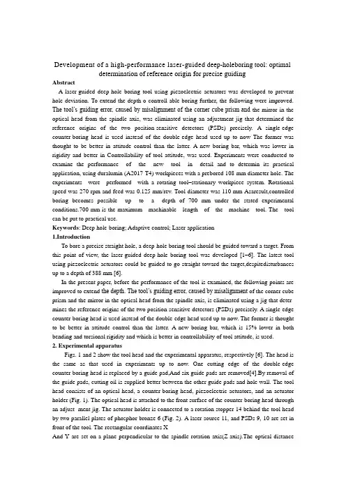
Development of a high-performance laser-guided deep-holeboring tool: optimal determination of reference origin for precise guidingAbstractA laser-guided deep-hole boring tool using piezoelectric actuators was developed to prevent hole deviation. To extend the depth o controll able boring further, the following were improved. The tool’s guiding error, caused by misalignment of the corner cube prism and the mirror in the optical head from the spindle axis, was eliminated using an adjustment jig that determined the reference origins of the two position-sensitive detectors (PSDs) precisely. A single-edge counter-boring head is used instead of the double-edge head used up to now The former was thought to be better in attitude control than the latter. A new boring bar, which was lower in rigidity and better in Controllability of tool attitude, was used. Experiments were conducted to examine the performance of the new tool in detail and to determin its practical application, using duralumin (A2017-T4) workpieces with a prebored 108-mm diameter hole. The experiments were performed with a rotating tool–stationary workpiece system. Rotational speed was 270 rpm and feed was 0.125 mm/rev. Tool diameter was 110 mm Asaresult,controlled boring becomes possible up to a depth of 700 mm under the stated experimental conditions.700 mm is the maximum machinable length of the machine tool. The tool can be put to practical use.Keywords: Deep hole-boring; Adaptive control; Laser application1.IntroductionTo bore a precise straight hole, a deep-hole boring tool should be guided toward a target. From this point of view, the laser-guided deep-hole boring tool was developed [1–6]. The latest tool using piezoelectric actuators could be guided to go straight toward the target,despitedisturbances up to a depth of 388 mm [6].In the present paper, before the performance of the tool is examined, the following points are improved to extend the depth. The tool’s guiding error, caused by misalignment of the corner cube prism and the mirror in the optical head from the spindle axis, is eliminated using a jig that deter- mines the reference origins of the two position-sensitive detectors (PSDs) precisely. A single-edge counter-boring head is used instead of the double-edge head used up to now. The former is thought to be better in attitude control than the latter. A new boring bar, which is 15% lower in both bending and torsional rigidity and which is better in controllability of tool attitude, is used.2. Experimental apparatusFigs. 1 and 2 show the tool head and the experimental apparatus, respectively [6]. The head is the same as that used in experiments up to now. One cutting edge of the double-edge counter-boring head is replaced by a guide pad,And six guide pads are removed[4].By removal of the guide pads, cutting oil is supplied better between the other guide pads and hole wall. The tool head consists of an optical head, a counter-boring head, piezoelectric actuators, and an actuator holder (Fig. 1). The optical head is attached to the front surface of the counter-boring head through an adjust- ment jig. The actuator holder is connected to a rotation stopper 14 behind the tool head by two parallel plates of phosphor bronze 6 (Fig. 2). A laser source 11, and PSDs 9, 10 are set in front of the tool. The rectangular coordinates XAnd Y are set on a plane perpendicular to the spindle rotation axis(Z-axis).The optical distancebetween a dichroic mirror in the optical head and PSD 10 for measuring tool inclina- tion is 2,040 mm [2].3. Method for detection of tool position and its inclinationFig. 3 shows the method used for measuring the tool position and its inclination. The laser beam, radiated from an argon laser, reaches the dichroic mirror 6 through the beam expander 5 and the half mirror 1. The dichroic mirror separates the two beams of wavelengths 514 nm (green) and 488 nm (blue). The green beam for measuring tool position passes through the dichroic mirror 6 and reachesthe corner cube prism 8. The reflected beam passes again through 6 and is deflected by the half mirror 1 toward dichroic mirror 2. By passing through the dichroic mirror 2, it reaches the PSD 9 used for measuring tool position. The blue beam for measuring tool inclination reaches the dichroic mirror 7 with an angle of incidence equal to 0°. The dichroic mirror 7 reflects the blue beam and trans- mits parts of the green beam, which are not completelyseparated by the dichroic mirror 6. The returning beam from the dichroic mirror 7 is deflected by the mirrors 6, 1, and 2, then passing through the dichroic mirror 4, and reaches the PSD 10 for measuring tool inclination. Re- flective characteristics of dichroic mirror 4 differs from that of dichroic mirror 7.4. Acquisition of data for controlling the toolData for tool attitude control are acquired from the two PSDs for tool position and its inclination every rotation of the counter-boring head. Until now, outputs of the two PSDs (measuring tool position and its inclination) some- times did not correspond well to the measured hole devia- tion. To determine what causes this, the following is exam- ined. The tool head with the optical head is supported by two V-blocks and is aligned on the Z-axis at the same longitudinal position as in the experiment. Then, the laser beam is radiated, and the optical head is rotated manually.Fig. 4 shows variations of outputs of two PSDs with encoder pulse during one rotation of the optical head fixed on the counter-boring head. Theoretically, outputs of two PSDs are constant during one rotation of the optical head corresponding to a 1,400 pulse of output of an encoder. Changes of X- and Y-outputs of tool position are caused by change of darkness of the laser spot because of interference and polarization of the laser beam. Changes of X- and Y- outputs of tool inclination are caused by inclination of the reflecting mirror in the optical head from the Z-axis. From the last experiment [6] on, tool position and its inclination are measured at rotational pulse position 700, where the brightness of the two PSDs are preferable at the same time.5. Misalignment of the optical parts in the optical headEven if the laser source and the PSDs for tool position and its inclination are aligned on Z-axis, hole deviation appeared. To discover its cause, the misalignment of the corner cube prism and inclination of reflecting mirror in the optical head from the Z-axis are examined.Fig. 5 shows all cases of alignment errors. Fig. 5(a) shows that the corner cube prism and the reflecting mirror are precisely aligned on the Z-axis. Figs. 5(b) and 5(c) are, the cases in which the corner cube prism is displaced by and the reflecting mirror is inclined byfrom the Z-axis, respectively.IncaseofFig.5(d),errorsofFigs.5(b)and(c) occur together. Fig. 5(e) shows the case when the optical head is inclined byduring the setup of the counter-boring head. Fig. 5(f) is the worst case, when all errors occur together. These errors cannot be eliminated by conventional adjustment. Therefore a new guiding strategy is developed to ensure that the tool can be guided straight, even if errors should occur.6. Optimal setup of reference origin for precise guidingFig. 6 shows the optimal setup method of reference origins. The laser source is aligned on the Z-axis [Fig. 6(a)] [6]. The optical head is fixed to the front surface of a cylindrical alignment jig through an adjustment jig. The alignment jig is inserted into the guide bush, which is fixed on a machine table, and the centers of both alignment jig and the optical head are aligned on Z-axis. Then the laser beam is radiated. Reflected beams reach the PSDs for tool position and its inclination. When the cylinder is rotated by hand, the rotational position, at which the output is most reliable, can be found. Next, the PSDs are moved until the spots lie at their centers. This position corresponds to the pulse position 700 of the encoder. The centers are reference origins for tool position and its inclination.At this rotational position,the optical head is fixed to the counter-boring head using the adjustment jig [Fig.6(b)].When the control starts, the tool head follows the alignment jig’s axis.7. Mechanism of tool displacementFig. 7 shows the mechanism of tool displacement. Fig. 7(a) shows the normal cutting condition [7]. The cutting force P is acting on the cutting edge and is counterbalanced by the guide pads. Fig. 7(b) shows the case where the tool is to correct for a deviation. A chain double-dashed line shows the hole wall before correction of hole deviation. A Directed line shows the direction of the correction.When the tool is controlled to incline toward the direction of the directed line, a cutting edge set ahead of the guide pads overcuts the hole wall. When the guide pad on the opposite side comes to the position of the overcutting zone, the cutting edge leaves a noncutting zone on the hole wall Opposite the overcutting zone.As a result,tool shifts toward the direction of the directed line.In the case of double-edge counter-boring head, the cut- ting force acting on one cutting edge is balanced by the force that acts on the other cutting edge [7]. As a result, the head is easy to vibrate, and the mechanism of tool displace- ment does not function well.Form: Precision Engineering 24 (2000) 9–14 开发高性能的激光制导deep-holeboring工具:最佳测定参考来源精确指导摘要激光制导深孔钻具使用压电致动器是防止孔偏差。
机械专业毕业设计外文翻译10
翻译部分英文部分ADV ANCED MACHINING PROCESSESAs the hardware of an advanced technology becomes more complex, new and visionary approaches to the processing of materials into useful products come into common use. This has been the trend in machining processes in recent years.. Advanced methods of machine control as well as completely different methods of shaping materials have permitted the mechanical designer to proceed in directions that would have been totally impossible only a few years ago.Parallel development in other technologies such as electronics and computers have made available to the machine tool designer methods and processes that can permit a machine tool to far exceed the capabilities of the most experienced machinist.In this section we will look at CNC machining using chip-making cutting tools. CNC controllers are used to drive and control a great variety of machines and mechanisms, Some examples would be routers in wood working; lasers, plasma-arc, flame cutting, and waterjets for cutting of steel plate; and controlling of robots in manufacturing and assembly. This section is only an overview and cannot take the place of a programming manual for a specific machine tool. Because of the tremendous growth in numbers and capability of comp uters ,changes in machine controls are rapidly and constantly taking place. The exciting part of this evolution in machine controls is that programming becomeseasier with each new advanced in this technology.Advantages of Numerical ControlA manually operated machine tool may have the same physical characteristics as a CNC machine, such as size and horsepower. The principles of metal removal are the same. The big gain comes from the computer controlling the machining axes movements. CNC-controlled machine tools can be as simple as a 2-axis drilling machining center (Figure O-1). With a dual spindle machining center, the low RPM, high horsepower spindle gives high metal removal rates. The high RPM spindle allows the efficient use of high cutting speed tools such as diamonds and small diameter cutters (Figure O-2). The cutting tools that remove materials are standard tools such as milling cutters, drills, boring tools, or lathe tools depending on the type of machine used. Cutting speeds and feeds need to be correct as in any other machining operation. The greatest advantage in CNC machining comes from the unerring and rapid positioning movements possible. A CNC machine does dot stop at the end of a cut to plan its next move; it does not get fatigued; it is capable of uninterrupted machining error free, hour after hour. A machine tool is productive only while it is making chips.Since the chip-making process is controlled by the proper feeds and speeds, time savings can be achieved by faster rapid feed rates. Rapid feeds have increased from 60 to 200 to 400 and are now often approaching 1000 inches per minute (IPM). These high feed rates can pose a safety hazard to anyone within the working envelope of the machine tool.Complex contoured shapes were extremely difficult to product prior to CNC machining .CNC has made the machining of these shapes economically feasible. Design changes on a part are relatively easy to make by changing the program that directs the machine tool.A CNC machine produces parts with high dimensional accuracy and close tolerances without taking extra time or special precautions, CNC machines generally need less complex work-holding fixtures, which saves time by getting the parts machined sooner. Once a program is ready and production parts, each part will take exactly the same amount of time as the previous one. This repeatability allows for a very precise control of production costs. Another advantage of CNC machining is the elimination of large inventories; parts can be machined as needs .In conventional production often a great number of parts must be made at the same time to be cost effective. With CNC even one piece can be machined economically .In many instances, a CNC machine can perform in one setup the same operations that would require several conventional machines.With modern CNC machine tools a trained machinist can program and product even a single part economically .CNC machine tools are used in small and large machining facilities and range in size from tabletop models to huge machining centers. In a facility with many CNC tools, programming is usually done by CNC programmers away from the CNC tools. The machine control unit (MCU) on the machine is then used mostly for small program changes or corrections. Manufacturing with CNC tools usually requires three categories of persons. The first is the programmer, who is responsible for developing machine-ready code. The next person involved is the setup person, who loads the raw stork into the MCU, checks that the co rrect tools are loaded, and makes the first part. The third person is the machine and unloads the finished parts. In a small company, one person is expected to perform all three of these tasks.CNC controls are generally divided into two basic categories. One uses a ward address format with coded inputs such as G and M codes. The other users a conversational input; conversational input is also called user-friendly or prompted input. Later in this section examples of each of these programming formats in machining applications will be describes.CAM and CNCCAM systems have changed the job of the CNC programmer from one manually producing CNC code to one maximizing the output of CNC machines. Since CNC machine tools are made by a great number of manufacturers, many different CNC control units are in use. Control units from different manufacturers use a variety of program formats and codes. Many CNC code words are identical for different controllers, but a great number vary from one to another.To produce an identical part on CNC machine tools with different controllers such as one by FANCU, OKUMA or DYNAPATH, would require completely different CNC codes. Each manufacturer is constantly improving and updating its CNC controllers. These improvements often include additional code words plus changes in how the existing code works.A CAM systems allows the CNC programmer to concentrate on the creation of an efficient machining process, rather then relearning changed code formats. A CNC programmer looks atthe print of a part and then plans the sequence of machining operations necessary to make it (Figure O-3). This plan includes everything, from the selection of possible CNC machine tools, to which tooling to use, to how the part is held while machining takes place. The CNC programmer has to have a thorough understanding of all the capacities and limitations of the CNC machine tools that a program is to be made for. Machine specifications such as horsepower, maximum spindle speeds, workpiece weight and size limitations, and tool changer capacity are just some of the considerations that affect programming.Another area of major importance to the programmer is the knowledge of machining processes. An example would be the selection of the surface finish requirement specified in the part print. The sequence of machining processes is critical to obtain acceptable results. Cutting tool limitations have to be considered and this requires knowledge of cutting tool materials, tool types, and application recommendations.A good programmer will spend a considerable amount of time in researching the rapidly growing volume of new and improved tools and tool materials. Often the tool that was on the cutting edge of technology just two years ago is now obsolete. Information on new tools can come from catalogs or tool manufacturers' tooling engineers. Help in tool selection or optimum tool working conditions can also be obtained from tool manufacturer software. Examples would be Kennametal's "TOOLPRO", software designed to help select the best tool grade, speed, and feed rates for different work materials in turning application. Another very important feature of "TOOLPRO" is the display of the horsepower requirement for each machining selection. This allow the programmer to select a combination of cutting speed, feed rate, and depth of cut that equals the machine's maximum horsepower for roughing cuts. For a finishing cut, the smallest diameter of the part being machined is selected and then the cutting speed varied until the RPM is equal to the maximum RPM of the machine. This helps in maximizing machining efficiency. Knowing the horsepower requirement for a cut is critical if more than one tool is cutting at the same time.Software for a machining center application would be Ingersoll Tool Company's "Actual Chip Thickness", a program used to calculate the chip thickness in relation to feed-per-tooth for a milling cutter, especially during a shallow finishing cut. Ingersoll's "Rigidity Analysis" software ealculates tool deflection for end mills as a function of tool stiffness and tool force.To this point we looked at some general qualifications that a programmer should possess. Now we examine how a CAM system works. Point Control Company's SmartCam system uses the following approach. First, the programmer makes a mental model of the part to be machined. This includes the kind of machining to be performed-turning or milling. Then the part print is studied to develop a machining sequence, roughing and finishing cuts, drilling, tapping, and boring operations. What work-holding device is to be used, a vise or fixture or clamps? After these considerations, computer input can be started. First comes the creation of a JOBPLAN. This JOBPLAN consists of entries such as inch or metric units, machine type, part ID, type of workpiece material, setup notes, and a description of the required tools.This line of information describes the tool by number, type, and size and includes theappropriate cutting speed and feed rate. After all the selected tools are entered, the file is saved.The second programming step is the making of the part. This represents a graphic modeling of the projected machining operation. After selecting a tool from the prepared JOBPLAN, parameters for the cutting operation are entered. For a drill, once the coordinate location of the hole and the depth are given, a circle appears on that spot. If the location is incorrect, the UNDO command erases this entry and allows you to give new values for this operation. When an end mill is being used, cutting movements (toolpath) are usually defined as lines and arcs. As a line is programmed, the toolpath is graphically displayed and errors can be corrected instantly.At any time during programming, the command SHOWPATH will show the actual toolpath for each of the programmed tools. The tools will be displayed in the sequence in which they will be used during actual machining. If the sequence of a tool movement needs to be changed, a few keystrokes will to that.Sometimes in CAM the programming sequence is different from the actual machining order. An example would be the machining of a pocket in a part. With CAM, the finished pocket outline is programmed first, then this outline is used to define the ro ughing cuts to machine the pocket. The roughing cuts are computer generated from inputs such as depth and width of cut and how much material to leave for the finish cut. Different roughing patterns can be tried out to allow the programmer to select the most efllcient one for the actual machining cuts. Since each tool is represented by a different color, it is easy to observe the toolpath made by each one.A CAM system lets the programmer view the graphics model from varying angles, such as a top, front, side, or isometric view. A toolpath that looks correct from a top view, may show from a front view that the depth of the cutting tool is incorrect. Changes can easily be made and seen immediately.When the toolpath and the sequence of operations are satisfactory, machine ready code has to be made. This is as easy as specifying the CNC machine that is to be used to machine the part. The code generator for that specific CNC machin e during processing accesses four different files. The JOBPLAN file for the tool information and the GRAPHICE file for the toolpath and cutting sequence. It also uses the MACHINE DEFINE file which defines the CNC code words for that specific machine. This file also supplies data for maximum feed rates, RPM, toolchange times, and so on. The fourth file taking part in the code generating process is the TEMPLATE file. This file acts like a ruler that produces the CNC code with all of its parts in the right place and sequence. When the code generation is complete, a projected machining time is displayed. This time is calculated from values such as feed rates and distances traveled, noncutting movements at maximum feed rates between points, tool change times, and so on. The projected machining time can be revised by changing tooling to allow for higher metal removal rates or creating a more efficient toolpath. This display of total time required can also be used to estimate production costs. If more then one CNC machine tool is available to machine this part, making code and comparing the machining time may show that one machine is more efficient than the others.CAD/CAMAnother method of creating toolpath is with the use of a Computer-aided Drafting (CAD) file. Most machine drawings are created using computers with the description and part geometry stored in the computer database. SmartCAM, though its CAM CONNECTION, will read a CAD file and transfer its geometry represents the part profile, holes, and so on. The programmer still needs to prepare a JOBPLAN with all the necessary tools, but instead of programming a profile line by line, now only a tool has to be assigned to an existing profile. Again, using the SHOWPA TH function will display the toolpath for each tool and their sequence. Constant research and developments in CAD/CAM interaction will change how they work with each other. Some CAD and CAM programs, if loaded on the same computer, make it possible to switch between the two with a few keystrokes, designing and programming at the same time.The work area around the machine needs to be kept clean and clear of obstructions to prevent slipping or tripping. Machine surfaces should not be used as worktables. Use proper lifting methods to handle heavy workpieces, fixtures, or heavy cutting tools. Make measurements only when the spindle has come to a complete standstill. Chips should never be handled with bare hands.Before starting the machine make sure that the work-holding device and the workpiece are securely fastened. When changing cutting tools, protect the workpiece being machined from damage, and protect your hands from sharp cutting edges. Use only sharp cutting tools. Check that cutting tools are installed correctly and securely.Do not operate any machine controls unless you understand their function and what the y will do.The Early Development Of Numerically Controlled Machine ToolsThe highly sophisticated CNC machine tools of today, in the vast and diverse range found throughout the field of manufacturing processing, started from very humble beginnings in a number of the major industrialized countries. Some of the earliest research and development work in this field was completed in USA and a mention will be made of the UK's contribution to this numerical control development.A major problem occurred just after the Second World War, in that progress in all areas of military and commercial development had been so rapid that the levels of automation and accuracy required by the modern industrialized world could not be attained from the lab our intensive machines in use at that time. The question was how to overcome the disadvantages of conventional plant and current manning levels. It is generally ackonwledged that the earliest work into numerical control was the study commissioned in 1947 by the US governme nt. The study's conclusion was that the metal cutting industry throughout the entire country could not copy with the demands of the American Air Force, let alone the rest of industry! As a direct result of the survey, the US Air Force contracted the Persons Corporation to see if they could develop a flexible, dynamic, manufacturing system which would maximize productivity. TheMassachusetts Institute of Technology (MIT) was sub-contracted into this research and development by the Parsons Corporation, during the period 1949-1951,and jointly they developed the first control system which could be adapted to a wide range of machine tools. The Cincinnati Machine Tool Company converted one of their standard 28 inch "Hydro-Tel" milling machines or a three-axis automatic milling made use of a servo-mechanism for the drive system on the axes. This machine made use of a servomechanism for the drive system on the axes, which controlled the table positioning, cross-slide and spindle head. The machine cab be classified as the first truly three axis continuous path machine tool and it was able to generate a required shape, or curve, by simultaneous slide way motions, if necessary.At about the same times as these American advances in machine tool control were taking Place, Alfred Herbert Limited in the United Kingdom had their first Mutinous path control system which became available in 1956.Over the next few years in both the USA and Europe, further development work occurred. These early numerical control developments were principally for the aerospace industry, where it was necessary to cut complex geometric shapes such as airframe components and turbine blades. In parallel with this development of sophisticated control systems for aerospace requirements, a point-to-point controller was developed for more general machining applications. These less sophisticated point-to-point machines were considerably cheaper than their more complex continuous path cousins and were used when only positional accuracy was necessary. As an example of point-to-point motion on a machine tool for drilling operations, the typical movement might be fast traverse of the work piece under the drill's position-after drilling the hole, anther rapid move takes place to the next hole's position-after retraction of the drill. Of course, the rapid motion of the slideways could be achieved by each axis in a sequential and independent manner, or simultaneously. If a separate control was utilisec for each axis, the former method of table travel was less esse ntial to avoid any backlash in the system to obtain the required degree of positional accuracy and so it was necessary that the approach direction to the next point was always the same.The earliest examples of these cheaper point-to-point machines usually did not use recalculating ball screws; this meant that the motions would be sluggish, and sliderways would inevitably suffer from backlash, but more will be said about this topic later in the chapter.The early NC machines were, in the main, based upon a modified milling machine with this concept of control being utilized on turning, punching, grinding and a whole host of other machine tools later. Towards the end of the 1950s,hydrostatic slideways were often incorporated for machine tools of highly precision, which to sonic extent overcame the section problem associated with conventional slideway response, whiles averaging-out slideway inaccuracy brought about a much increased preasion in the machine tool and improved their control characteristics allows "concept of the machining center" was the product of this early work, as it allowed the machine to manufacture a range of components using a wide variety of machining processes at a single set-up, without transfer of workpieces to other variety machine tools. A machining center differed conceptually in its design from that of a milling machine, In that thecutting tools could be changed automatically by the transfer machanism, or selector, from the magazine to spindle, or vice versa.In this ductively and the automatic tool changing feature enabled the machining center to productively and efficiently machine a range of components, by replacing old tools for new, or reselecting the next cutter whilst the current machining process is in cycle.In the mid 1960s,a UK company, Molins, introduced their unique "System 24" which was meant represent the ability of a system to machine for 24 hours per day. It could be thought of as a "machining complex" which allowed a series of NC single purpose machine tools to be linked by a computerized conveyor system. This conveyor allowed the work pieces to be palletized and then directed to as machine tool as necessary. This was an early, but admirable, attempt at a form of Flexible manufacturing System concept, but was unfortunately doomed to failure. Its principal weakness was that only a small proportion of component varieties could be machine at any instant and that even fewer work pieces required the same operations to be performed on them. These factors meant that the utilization level was low, coupled to the fact that the machine tools were expensive and allowed frequent production bottlenecks of work-in-progress to arise, which further slowed down the whole operation.The early to mid-1970s was a time of revolutionary in the area of machine tool controller development, when the term computerized numerical control (CNC) became a reality. This new breed of controllers gave a company the ability to change work piece geometries, together with programs, easily with the minimum of development and lead time, allowing it to be economically viable to machine small batches, or even one-off successfully. The dream of allowing a computerized numerical controller the flexibility and ease of program editing in a production environment became a reality when two ralated factors occurred.These were:the development of integrated circuits, which reduces electronics circuit size, giving better maintenance and allowing more standardization of desing; that general purpose computers were reduced in size coupled to the fact that their cost of production had fallen considerably.The multipie benefits of cheaper electorics with greater reliability have result in the CNC fitted to the machine tools today, with the power and sophistication progtessing considerably in the last few years, allowing an almost artificial intelligence(AI) to the latest systems. Over the years, the machine tools builders have produced a large diversity in the range of applications of CNC and just some of those development will be reviewed in V olume Ⅲ。
机械设计外文翻译--- 轴承的摩擦与润滑
毕业设计(论文)外文翻译毕业设计(论文)题目:外文题目:Friction , Lubrication of Bearing 译文题目:轴承的摩擦与润滑系别:机械工程系专业:机械工程制造及其自动化班级:学号:姓名:指导教师:2012年03 月03 日外文文献原文:Friction , Lubrication of BearingIn many of the problem thus far , the student has been asked to disregard or neglect friction . Actually , friction is present to some degree whenever two parts are in contact and move on each other. The term friction refers to the resistance of two or more parts to movement.Friction is harmful or valuable depending upon where it occurs. friction is necessary for fastening devices such as screws and rivets which depend upon friction to hold the fastener and the parts together. Belt drivers, brakes, and tires are additional applications where friction is necessary.The friction of moving parts in a machine is harmful because it reduces the mechanical advantage of the device. The heat produced by friction is lost energy because no work takes place. Also , greater power is required to overcome the increased friction. Heat is destructive in that it causes expansion. Expansion may cause a bearing or sliding surface to fit tighter. If a great enough pressure builds up because made from low temperature materials may melt.There are three types of friction which must be overcome in moving parts: (1)starting, (2)sliding,and(3)rolling. Starting friction is the friction between two solids that tend to resist movement. When two parts are at a state of rest, the surface irregularities of both parts tend to interlock and form a wedging action. To produce motion in these parts, the wedge-shaped peaks and valleys of the stationary surfaces must be made to slide out and over each other. The rougher the two surfaces, the greater is starting friction resulting from their movement .Since there is usually no fixed pattern between the peaks and valleys of two mating parts, the irregularities do not interlock once the parts are in motion but slide over each other. The friction of the two surfaces is known as sliding friction. As shown in figure ,starting friction is always greater than sliding friction .Rolling friction occurs when roller devces are subjected to tremendous stress which cause the parts to change shape or deform. Under these conditions, the material in front of a roller tends to pile up and forces the object to roll slightly uphill. This changing of shape , known as deformation, causes a movement of molecules. As a result ,heat is produced from the added energy required to keep the parts turning and overcome friction.The friction caused by the wedging action of surface irregularities can be overcome partly by the precision machining of the surfaces. However, even these smooth surfaces may require the use of a substance between them to reduce the friction still more. This substance is usually a lubricant which provides a fine, thin oil film. The film keeps the surfaces apart and prevents the cohesive forces of the surfaces from coming in close contact and producing heat .Another way to reduce friction is to use different materials for the bearing surfaces and rotating parts.This explains why bronze bearings, soft alloys, and copper and tin iolite bearings are used with both soft and hardened steel shaft. The iolite bearing is porous. Thus, when the bearing is dipped in oil, capillary action carries the oil through the spaces of the bearing. This type of bearing carries its own lubricant to the points where the pressures are the greatest.Moving parts are lubricated to reduce friction, wear, and heat. The most commonly used lubricants are oils, greases, and graphite compounds. Each lubricant serves a different purpose. The conditions under which two moving surfaces are to work determine the type of lubricant to be used and the system selected for distributing the lubricant.On slow moving parts with a minimum of pressure, an oil groove is usually sufficient to distribute the required quantity of lubricant to the surfaces moving on each other .A second common method of lubrication is the splash system in which parts moving in a reservoir of lubricant pick up sufficient oil which is then distributed to all moving parts during each cycle. This system is used in the crankcase of lawn-mower engines to lubricate the crankshaft, connecting rod ,and parts of the piston.A lubrication system commonly used in industrial plants is the pressure system. In this system, a pump on a machine carries the lubricant to all of the bearing surfaces at a constant rate and quantity.There are numerous other systems of lubrication and a considerable number of lubricants available for any given set of operating conditions. Modern industry pays greater attention to the use of the proper lubricants than at previous time because of the increased speeds, pressures, and operating demands placed on equipment and devices.Although one of the main purposes of lubrication is reduce friction, any substance-liquid , solid , or gaseous-capable of controlling friction and wear between sliding surfaces can be classed as a lubricant.V arieties of lubricationUnlubricated sliding. Metals that have been carefully treated to remove all foreign materials seize and weld to one another when slid together. In the absence of such a high degree of cleanliness, adsorbed gases, water vapor ,oxides, and contaminants reduce frictio9n and the tendency to seize but usually result in severe wear; this is called “unlubricated ”or dry sliding.Fluid-film lubrication. Interposing a fluid film that completely separates the sliding surfaces results in fluid-film lubrication. The fluid may be introduced intentionally as the oil in the main bearing of an automobile, or unintentionally, as in the case of water between a smooth tuber tire and a wet pavement. Although the fluid is usually a liquid such as oil, water, and a wide range of other materials, it may also be a gas. The gas most commonly employed is air.Boundary lubrication. A condition that lies between unlubricated sliding and fluid-film lubrication isreferred to as boundary lubrication, also defined as that condition of lubrication in which the friction between surfaces is determined by the properties of the surfaces and properties of the lubricant other than viscosity. Boundary lubrication encompasses a significant portion of lubrication phenomena and commonly occurs during the starting and stopping off machines.Solid lubrication. Solid such as graphite and molybdenum disulfide are widely used when normal lubricants do not possess sufficient resistance to load or temperature extremes. But lubricants need not take only such familiar forms as fats, powders, and gases; even some metals commonly serve as sliding surfaces in some sophisticated machines.Function of lubricantsAlthough a lubricant primarily controls friction and ordinarily does perform numerous other functions, which vary with the application and usually are interrelated .Friction control. The amount and character of the lubricant made available to sliding surfaces have a profound effect upon the friction that is encountered. For example, disregarding such related factors as heat and wear but considering friction alone between the same surfaces with on lubricant. Under fluid-film conditions, friction is encountered. In a great range of viscosities and thus can satisfy a broad spectrum of functional requirements. Under boundary lubrication conditions , the effect of viscosity on friction becomes less significant than the chemical nature of the lubricant.Wear control. wear occurs on lubricated surfaces by abrasion, corrosion ,and solid-to-solid contact wear by providing a film that increases the distance between the sliding surfaces ,thereby lessening the damage by abrasive contaminants and surface asperities.T emperature control. Lubricants assist in controlling corrosion of the surfaces themselves is twofold. When machinery is idle, the lubricant acts as a preservative. When machinery is in use, the lubricant controls corrosion by coating lubricated parts with a protective film that may contain additives to neutralize corrosive materials. The ability of a lubricant to control corrosion is directly relatly to the thickness of the lubricant film remaining on the metal surfaces and the chermical composition of the lubricant.Other functionsLubrication are frequently used for purposes other than the reduction of friction. Some of these applications are described below.Power transmission. Lubricants are widely employed as hydraulic fluids in fluid transmission devices.Insulation. In specialized applications such as transformers and switchgear , lubricants with highdielectric constants acts as electrical insulators. For maximum insulating properties, a lubricant must be kept free of contaminants and water.Shock dampening. Lubricants act as shock-dampening fluids in energy transferring devices such as shock absorbers and around machine parts such as gears that are subjected to high intermittent loads.Sealing. Lubricating grease frequently performs the special function of forming a seal to retain lubricants or to exclude contaminants.The object of lubrication is to reduce friction ,wear , and heating of machine pars which move relative to each other. A lubricant is any substance which, when inserted between the moving surfaces, accomplishes these purposes. Most lubricants are liquids(such as mineral oil, silicone fluids, and water),but they may be solid for use in dry bearings, greases for use in rolling element bearing, or gases(such as air) for use in gas bearings. The physical and chemical interaction between the lubricant and lubricating surfaces must be understood in order to provide the machine elements with satisfactory life.The understanding of boundary lubrication is normally attributed to hardy and doubleday , who found the extrememly thin films adhering to surfaces were often sufficient to assist relative sliding. They concluded that under such circumstances the chemical composition of fluid is important, and they introduced the term “boundary lubrication”. Boundary lubrication is at the opposite end of the spectrum from hydrodynamic lubrication.Five distinct of forms of lubrication that may be defined :(a) hydrodynamic;(b)hydrostatic;(c)elastohydrodynamic (d)boundary; (e)solid film.Hydrodynamic lubrication means that the load-carrying surfaces of the bearing are separated by a relatively thick film of lubricant, so as to prevent metal contact, and that the stability thus obtained can be explained by the laws of the lubricant under pressure ,though it may be; but it does require the existence of an adequate supply at all times. The film pressure is created by the moving surfaces itself pulling the lubricant under pressure, though it maybe. The film pressure is created by the moving surface to creat the pressure necessary to separate the surfaces against the load on the bearing . hydrodynamic lubrication is also called full film ,or fluid lubrication .Hydrostatic lubrication is obtained by introducing the lubricant ,which is sometime air or water ,into the load-bearing area at a pressure high enough to separate the surface with a relatively thick film of lubricant. So ,unlike hydrodynanmic lubrication, motion of one surface relative to another is not required .Elasohydrodynamic lubrication is the phenomenon that occurs when a lubricant is introduced between surfaces which are in rolling contact, such as mating gears or rolling bearings. The mathematical explanation requires the hertzian theory of contact stress and fluid mechanics.When bearing must be operated at exetreme temperatures, a solid film lubricant such as graphite or molybdenum disulfide must be use used because the ordinary mineral oils are not satisfactory. Must research is currently being carried out in an effort, too, to find composite bearing materials with low wear rates as well as small frictional coefficients.In a journal bearing, a shaft rotates or oscillates within the bearing , and the relative motion is sliding . in an antifriction bearing, the main relative motion is rolling . a follower may either roll or slide on the cam. Gear teeth mate with each other by a combination of rolling and sliding . pistions slide within their cylinders. All these applications require lubrication to reduce friction ,wear, and heating.The field of application for journal bearing s is immense. The crankshaft and connecting rod bearings of an automotive engine must poerate for thousands of miles at high temperatures and under varying load conditions . the journal bearings used in the steam turbines of power generating station is said to have reliabilities approaching 100 percent. At the other extreme there are thousands of applications in which the loads are light and the service relatively unimportant. a simple ,easily installed bearing is required ,suing little or no lubrication. In such cases an antifriction bearing might be a poor answer because because of the cost, the close ,the radial space required ,or the increased inertial effects. Recent metallurgy developments in bearing materials , combined with increased knowledge of the lubrication process, now make it possible to design journal bearings with satisfactory lives and very good reliabilities.参考文献:1. Chambers T. L., Parkinson A. R., 1998, “Knowledge Representation and Conversion ofHybridExpert Systems.” Transactions of the ASME, v 120,pp 468-4742. Koelsch, James R., 1999, “Software boosts mold design efficiency“ Molding Systems,v57, n 3,p16-23.3. Lee, Rong-Shean, Chen, Y uh-Min, Lee, Chang-Zou,1997 “Development of a concurrentmolddesign system: A knowledge-based approach”, Computer Integrated Manufacturing Systems, v 10,n 4, p 287-3074. Steadman Sally, Pell Kynric M, 1995, “ Expert systems in engineering design: An applicationforinjection molding of plastic parts“ Journal of Intelligent Manufacturing, v6, p 347-353.5. Fernandez A., Castany J., Serraller F., Javierre C., 1997, “CAD/CAE assistant for the designofmolds and prototypes for in jection of thermoplastics “Information Technological, v 8, p 117-124.6. Douglas M Bryce, 1997, “Plastic injection molding -Material selection and product design”, v 2,pp1-48.7. Douglas M Bryce, 1997, “Plastic injection molding-Mold design fundamentals”, v2, pp 1-120 中文译文:轴承的摩擦与润滑现在看来,有很多这种情况,许多学生在被问到关于摩擦的问题时,往往都没引起足够的重视,甚至是忽视它。
机械毕业设计英文外文翻译407驱动桥微分
附录(1)外文文献Drive axle/differentialAll vehicles have some type of drive axle/differential assembly incorporated into the driveline. Whether it is front, rear or four wheel drive, differentials are necessary for the smooth application of engine power to the road.PowerflowSee Figure 1The drive axle must transmit power through a 90°angle. The flow of power in conventional front engine/rear wheel drive vehicles moves from the engine to the drive axle in approximately a straight line. However, at the drive axle, the power must be turned at right angles (from the line of the driveshaft) and directed to the drive wheels.This is accomplished by a pinion drive gear, which turns a circular ring gear. The ring gear is attached to a differential housing, containing a set of smaller gears that are splined to the inner end of each axle shaft. As the housing is rotated, the internal differential gears turn the axle shafts, which are also attached to the drive wheels.Figure 1 Component parts of a typical driven axleassemblyDifferential operationSee Figure 2The differential is an arrangement of gears with two functions: to permit the rear wheels to turn at different speeds when cornering and to divide the power flow between both rear wheels.The accompanying illustration has been provided to help understand how this occurs. The drive pinion, which is turned by the driveshaft, turns the ring gear (1).The ring gear, which is attached to the differential case, turns the case (2).The pinion shaft, located in a bore in the differential case, is at right angles to the axle shafts and turns with the case (3).The differential pinion (drive) gears are mounted on the pinion shaft and rotate with the shaft (4).Differential side gears (driven gears) are meshed with the pinion gears and turn with the differential housing and ring gear as a unit (5).The side gears are splined to the inner ends of the axle shafts and rotate the shafts as the housing turns (6).When both wheels have equal traction, the pinion gears do not rotate on the pinion shaft, since the input force of the pinion gears is divided equally between the two side gears (7).When it is necessary to turn a corner, the differential gearing becomes effective and allows the axle shafts to rotate at different speeds (8).As the inner wheel slows down, the side gear splined to the inner wheel axle shaft also slows. The pinion gears act as balancing levers by maintaining equal tooth loads to both gears, while allowing unequal speeds of rotation at the axle shafts. If the vehicle speed remains constant, and the inner wheel slows down to 90 percent of vehicle speed, the outer wheel will speed up to 110 percent. However, because this system isknown as an open differential, if one wheel should become stuck (as in mud or snow), all of the engine power can be transferred to only one wheel.Figure 2 Overview of differential gear operatingprinciples.Limited-slip and locking differential operationSee Figure 3Limited-slip and locking differentials provide the driving force to the wheel with the best traction before the other wheel begins to spin. This is accomplished through clutch plates, cones or locking pawls.The clutch plates or cones are located between the side gears and the inner walls of the differential case. When they are squeezed togetherthrough spring tension and outward force from the side gears, three reactions occur. Resistance on the side gears causes more torque to be exerted on the clutch packs or clutch cones. Rapid one wheel spin cannot occur, because the side gear is forced to turn at the same speed as the case. So most importantly, with the side gear and the differential case turning at the same speed, the other wheel is forced to rotate in the same direction and at the same speed as the differential case. Thus, driving force is applied to the wheel with the better traction.Locking differentials work nearly the same as the clutch and cone type of limited slip, except that when tire speed differential occurs, the unit will physically lock both axles together and spin them as if they were a solid shaft.Figure 3 Limited-slip differentials transmit powerthrough the clutches or cones to drive the wheelhaving the best traction.Identifying a limited-slip drive axleMetal tags are normally attached to the axle assembly at the filler plug or to a bolt on the cover. During the life of the vehicle, these tags can become lost and other means must be used to identify the drive axle.To determine whether a vehicle has a limited-slip or a conventional drive axle by tire movement, raise the rear wheels off the ground. Place the transmission in PARK (automatic) or LOW (manual), and attempt to turn a drive wheel by hand. If the drive axle is a limited-slip type, it will be very difficult (or impossible) to turn the wheel. If the drive axle is the conventional (open) type, the wheel will turn easily, and the opposing wheel will rotate in the reverse direction.Place the transmission in neutral and again rotate a rear wheel. If the axle is a limited-slip type, the opposite wheel will rotate in the same direction. If the axle is a conventional type, the opposite wheel will rotate in the opposite direction, if it rotates at all.Gear ratioSee Figure 4The drive axle of a vehicle is said to have a certain axle ratio. This number (usually a whole number and a decimal fraction) is actually a comparison of the number of gear teeth on the ring gear and the pinion gear. For example, a 4.11 rear means that theoretically, there are 4.11 teeth on the ring gear for each tooth on the pinion gear or, put another way, the driveshaft must turn 4.11 times to turn the wheels once. Actually, with a 4.11 ratio, there might be 37 teeth on the ring gear and 9 teeth on the pinion gear. By dividing the number of teeth on the pinion gear into the number of teeth on the ring gear, the numerical axle ratio (4.11) is obtained. This also provides a good method of ascertaining exactly which axle ratio one is dealing with.Another method of determining gear ratio is to jack up and support the vehicle so that both drive wheels are off the ground. Make a chalk mark on the drive wheel and the driveshaft. Put the transmission in neutral. Turn the wheel one complete turn and count the number of turns that the driveshaft/halfshaft makes. The number of turns that the driveshaft makes in one complete revolution of the drive wheel approximates the axle ratio.Figure 4 The numerical ratio of the drive axle is the number of the teeth on the ring gear divided by the number of the teeth on the pinion gear.(2)文献翻译驱动桥/微分所有车辆有某种类型的驱动桥/微分装配纳入动力传动系统。
机械设计外文翻译---工艺规程制订与并行工程
外文文献原稿和译文原稿Process Planning and Concurrent EngineeringT. Ramayah and Noraini IsmailABSTRACTTh e product design is the plan for the product and its components and subassemblies. To convert the product design into a physical entity, a manufacturing plan is needed. The activity of developing such a plan is called process planning. It is the link between product design and manufacturing. Process planning involves determining the sequence of processing and assembly steps that must be accomplished to make the product. In the present chapter, we examine processing planning and several related topics.Process PlanningPr ocess planning involves determining the most appropriate manufacturing and assembly processes and the sequence in which they should be accomplished to produce a given part or product according to specifications set forth in the product design documentation. The scope and variety of processes that can be planned are generally limited by the available processing equipment and technological capabilities of the company of plant. Parts that cannot be made internally must be purchased from outside vendors. It should be mentioned that the choice of processes is also limited by the details of the product design. This is a point we will return to later.Process planning is usually accomplished by manufacturing engineers. The processplanner must be familiar with the particular manufacturing processes available in the factory and be able to interpret engineering drawings. Based on the planner’s knowledge, skill, and experience, the processing steps are developed in the most logical sequence to make each part. Following is a list of the many decisions and details usually include within the scope of process planning..nterpretation of design drawings.The part of product design must be analyzed (materials, dimensions, tolerances, surface finished, etc.) at the start of the process planning procedure..Process and sequence.The process planner must select which processes are required and their sequence. A brief description of processing steps must be prepared..Equipment selection. In general, process planners must develop plans that utilize existing equipment in the plant. Otherwise, the component must be purchased, or an investment must be made in new equipment..Tools, dies, molds, fixtures, and gages.The process must decide what tooling is required for each processing step. The actual design and fabrication of these tools is usually delegated to a tool design department and tool room, or an outside vendor specializing in that type of tool is contacted..Methods analysis.Workplace layout, small tools, hoists for lifting heavy parts, even in some cases hand and body motions must be specified for manual operations. The industrial engineering department is usually responsible for this area..Work standards.Work measurement techniques are used to set time standards for each operation..Cutting tools and cutting conditions.These must be specified for machining operations, often with reference to standard handbook recommendations.Process planning for partsO r individual parts, the processing sequence is documented on a form called a route sheet. Just as engineering drawings are used to specify the product design, route sheets are used to specify the process plan. They are counterparts, one for product design, the other for manufacturing.Typical processing sequence to fabricate an individual part consists of: (1) a basic process, (2) secondary processes, (3) operations to enhance physical properties, and (4) finishing operations. A basic process determines the starting geometry of the work parts. Metal casting, plastic molding, and rolling of sheet metal are examples of basic processes. The starting geometry must often be refined by secondary processes, operations that transform the starting geometry (or close to final geometry). The secondary geometry processes that might be used are closely correlated to the basic process that provides the starting geometry. When sand casting is the basic processes, machining operations are generally the second processes. When a rolling mill produces sheet metal, stamping operations such as punching and bending are the secondary processes. When plastic injection molding is the basic process, secondary operations are often unnecessary, because most of the geometric features that would otherwise require machining can be created by the molding operation. Plastic molding and other operation that require no subsequent secondary processing are called net shape processes. Operations that require some but not much secondary processing (usually machining) are referred to as near net shape processes. Some impression die forgings are in this category. These parts can often be shaped in the forging operation (basic processes) so that minimal machining (secondary processing) is required.The geometry has been established, the next step for some parts is to improve their mechanical and physical properties. Operations to enhance properties do not alter the geometry of the part; instead, they alter physical properties. Heat treating operations on metal parts are the most common examples. Similar heating treatments are performed on glass to produce tempered glass. For most manufactured parts, these property-enhancing operations are not required in the processing sequence.Finally finish operations usually provide a coat on the work parts (or assembly) surface. Examples included electroplating, thin film deposition techniques, and painting. The purpose of the coating is to enhance appearance, change color, or protect the surface from corrosion, abrasion, and so forth. Finishing operations are not required on many parts; for example, plastic molding rarely require finishing. Whenfinishing is required, it is usually the final step in the processing sequence. Processing Planning for AssembliesTh e type of assembly method used for a given product depends on factors such as: (1) the anticipated production quantities; (2) complexity of the assembled product, for example, the number of distinct components; and (3) assembly processes used, for example, mechanical assembly versus welding. For a product that is to be made in relatively small quantities, assembly is usually performed on manual assembly lines. For simple products of a dozen or so components, to be made in large quantities, automated assembly systems are appropriate. In any case, there is a precedence order in which the work must be accomplished. The precedence requirements are sometimes portrayed graphically on a precedence diagram.Process planning for assembly involves development of assembly instructions, but in more detail .For low production quantities, the entire assembly is completed at a single station. For high production on an assembly line, process planning consists of allocating work elements to the individual stations of the line, a procedure called line balancing. The assembly line routes the work unit to individual stations in the proper order as determined by the line balance solution. As in process planning for individual components, any tools and fixtures required to accomplish an assembly task must be determined, designed, built, and the workstation arrangement must be laid out. Make or Buy DecisionAn important question that arises in process planning is whether a given part should be produced in the company’s own factory or purchased from an outside vendor, and the answer to this question is known as the make or buy decision. If the company does not possess the technological equipment or expertise in the particular manufacturing processes required to make the part, then the answer is obvious: The part must be purchased because there is no internal alternative. However, in many cases, the part could either be made internally using existing equipment, or it could be purchasedexternally from a vendor that process similar manufacturing capability.In our discussion of the make or buy decision, it should be recognized at the outset that nearly all manufactures buy their raw materials from supplies. A machine shop purchases its starting bar stock from a metals distributor and its sand castings from a foundry. A plastic molding plant buys its molding compound from a chemical company. A stamping press factory purchases sheet metal either fro a distributor or direct from a rolling mill. Very few companies are vertically integrated in their production operations all the way from raw materials, it seems reasonable to consider purchasing at least some of the parts that would otherwise be produced in its own plant. It is probably appropriate to ask the make or buy question for every component that is used by the company.Here are a number of factors that enter into the make or buy decision. One would think that cost is the most important factor in determining whether to produce the part or purchase it. If an outside vendor is more proficient than the company’s own plant in the manufacturing processes used to make the part, then the internal production cost is likely to be greater than the purchase price even after the vendor has included a profit. However, if the decision to purchase results in idle equipment and labor in the company’s own plant, then the apparent advantage of purchasing the part may be lost. Consider the following example make or Buy Decision.The quoted price for a certain part is $20.00 per unit for 100 units. The part can be produced in the company’s own plant for $28.00. The components of making the part are as follows:Unit raw material cost = $8.00 per unitDirect labor cost =6.00 per unitLabor overhead at 150%=9.00 per unitEquipment fixed cost =5.00 per unit________________________________Total =28.00 per unitShould the component by bought or made in-house?Solution: Although the vendor’s quote seems to favor a buy decision, let us consider the possible impact on plant operations if the quote is accepted. Equipment fixed cost of $5.00 is an allocated cost based on investment that was already made. If the equipment designed for this job becomes unutilized because of a decision to purchase the part, then the fixed cost continues even if the equipment stands idle. In the same way, the labor overhead cost of $9.00 consists of factory space, utility, and labor costs that remain even if the part is purchased. By this reasoning, a buy decision is not a good decision because it might be cost the company as much as $20.00+$5.0+$9.00=$34.00 per unit if it results in idle time on the machine that would have been used to produce the part. On the other hand, if the equipment in question can be used for the production of other parts for which the in-house costs are less than the corresponding outside quotes, then a buy decision is a good decision.ake or buy decision are not often as straightforward as in this example. A trend in recent years, especially in the automobile industry, is for companies to stress the importance of building close relationships with parts suppliers. We turn to this issue in our later discussion of concurrent engineering.Computer-aided Process PlanningHere is much interest by manufacturing firms in automating the task of process planning using computer-aided process planning (CAPP) systems. The shop-trained people who are familiar with the details of machining and other processes are gradually retiring, and these people will be available in the future to do process planning. An alternative way of accomplishing this function is needed, and CAPPsystems are providing this alternative. CAPP is usually considered to be part of computer-aided manufacturing (CAM). However, this tends to imply that CAM is a stand-along system. In fact, a synergy results when CAM is combined with computer-aided design to create a CAD/CAM system. In such a system, CAPP becomes the direct connection between design and manufacturing. The benefits derived from computer-automated process planning include the following: .Process rationalization and standardization. Automated process planning leads to more logical and consistent process plans than when process is done completely manually. Standard plans tend to result in lower manufacturing costs and higher product quality..Increased productivity of process planner. The systematic approach and the availability of standard process plans in the data files permit more work to be accomplished by the process planners..Reduced lead time for process planning. Process planner working with a CAPP system can provide route sheets in a shorter lead time compared to manual preparation..Improved legibility. Computer-prepared rout sheets are neater and easier to read than manually prepared route sheets..Incorporation of other application programs. The CAPP program can be interfaced with other application programs, such as cost estimating and work standards.Computer-aided process planning systems are designed around two approaches. These approaches are called: (1) retrieval CAPP systems and (2) generative CAPP systems .Some CAPP systems combine the two approaches in what is known as semi-generative CAPP.Concurrent Engineering and Design for ManufacturingOncurrent engineering refers to an approach used in product development in which the functions of design engineering, manufacturing engineering, and other functions are integrated to reduce the elapsed time required to bring a new product to market. Also called simultaneous engineering, it might be thought of as the organizationalProduct design Manufacturing engineering and process planning Production and assembly The “wall” bet ween design and manufacturing Product launch time, traditional design/manufacturing cycle Difference in product launch time (a)Traditional product development cycle Product design Sales and marketing Quality engineering Vendors Manufacturing engineering and process planning Production and assemblyProduct laugh time,concurrent engineering(b) Product development using concurrent engineeringcounterpart to CAD/CAM technology. In the traditional approach to launching a new product, the two functions of design engineering and manufacturing engineering tend to be separated and sequential, as illustrated in Fig.(1).(a).The product design department develops the new design, sometimes without much consideration given to the manufacturing capabilities of the company, There is little opportunity for manufacturing engineers to offer advice on how the design might be alerted to make it more manufacturability. It is as if a wall exits between design and manufacturing. When the design engineering department completes the design, it tosses the drawings and specifications over the wall, and only then does process planning begin.g.(1). Comparison: (a) traditional product development cycle and (b) product development using concurrent engineeringContrast, in a company that practices concurrent engineering, the manufacturing engineering department becomes involved in the product development cycle early on, providing advice on how the product and its components can be designed to facilitate manufacture and assembly. It also proceeds with early stages of manufacturing planning for the product. This concurrent engineering approach is pictured in Fig.(1).(b). In addition to manufacturing engineering, other function are also involved in the product development cycle, such as quality engineering, the manufacturing departments, field service, vendors supplying critical components, and in some cases the customer who will use the product. All if these functions can make contributions during product development to improve not only the new product’s function and performance, but also its produceability, inspectability, testability, serviceability, and maintainability. Through early involvement, as opposed to reviewing the final product design after it is too late to conveniently make any changes in the design, the duration of the product development cycle is substantially reduced.On current engineering includes several elements: (1) design for several manufacturing and assembly, (2) design for quality, (3) design for cost, and (4) design for life cycle. In addition, certain enabling technologies such as rapid prototyping, virtual prototyping, and organizational changes are required to facilitate the concurrent engineering approach in a company.Design for Manufacturing and AssemblyIt has been estimated that about 70% of the life cycle cost of a product is determined by basic decisions made during product design. These design decisions include the material of each part, part geometry, tolerances, surface finish, how parts are organized into subassemblies, and the assembly methods to be used. Once these decisions are made, the ability to reduce the manufacturing cost of the product is limited. For example, if the product designer decides that apart is to be made of analuminum sand casting but which processes features that can be achieved only by machining(such as threaded holes and close tolerances), the manufacturing engineer has no alternative expect to plan a process sequence that starts with sand casting followed by the sequence of machining operations needed to achieve the specified features .In this example, a better decision might be to use a plastic molded part that can be made in a single step. It is important for the manufacturing engineer to be given the opportunity to advice the design engineer as the product design is evolving, to favorably influence the manufacturability of the product.Erm used to describe such attempts to favorably influence the manufacturability of a new product are design for manufacturing (DFM) and design for assembly(DFA). Of course, DFM and DFA are inextricably linked, so let us use the term design for manufacturing and assembly (DFM/A). Design for manufacturing and assembly involves the systematic consideration of manufacturability and assimilability in the development of a new product design. This includes: (1) organizational changes and (2) design principle and guidelines..Organizational Changes in DFM/A.Effective implementation of DFM/A involves making changes in a company’s organization structure, either formally or informally, so that closer interaction and better communication occurs between design and manufacturing personnel. This can be accomplished in several ways: (1)by creating project teams consisting of product designers, manufacturing engineers, and other specialties (e.g. quality engineers, material scientists) to develop the new product design; (2) by requiring design engineers to spend some career time in manufacturing to witness first-hand how manufacturability and assembility are impacted by a product’s design; and (3)by assigning manufacturing engineers to the product design department on either a temporary or full-time basis to serve as reducibility consultants..Design Principles and Guidelines.DFM/A also relies on the use of design principles and guidelines for how to design a given product to maximize manucturability and assembility. Some of these are universal design guidelines that can be applied to nearly any product design situation. There are design principles thatapply to specific processes, and for example, the use of drafts or tapers in casted and molded parts to facilitate removal of the part from the mold. We leave these more process-specific guidelines to texts on manufacturing processes.The guidelines sometimes conflict with one another. One of the guidelines is to “simplify part geometry, avoid unnecessary features”. But another guideline in the same table states that “spe cial geometric features must sometimes be added to components” to design the product for foolproof assembly. And it may also be desirable to combine features of several assembled parts into one component to minimize the number of parts in the product. In these instances, design for part manufacture is in conflict with design for assembly, and a suitable compromise must be found between the opposing sides of the conflict.译文工艺规程制订与并行工程T. Ramayah and Noraini Ismail摘要产品设计是用于产品,及它的部件装配的计划。
机械设计外文文献翻译、中英文翻译
机械设计外文文献翻译、中英文翻译unavailable。
The first step in the design process is to define the problem and XXX are defined。
the designer can begin toXXX evaluated。
and the best one is XXX。
XXX.Mechanical DesignA XXX machines include engines。
turbines。
vehicles。
hoists。
printing presses。
washing machines。
and XXX and methods of design that apply to XXXXXX。
cams。
valves。
vessels。
and mixers.Design ProcessThe design process begins with a real need。
Existing apparatus may require XXX。
efficiency。
weight。
speed。
or cost。
while new apparatus may be XXX。
To start。
the designer must define the problem and XXX。
ideas and concepts are generated。
evaluated。
and refined until the best one is XXX。
XXX.XXX。
assembly。
XXX.During the preliminary design stage。
it is important to allow design XXX if some ideas may seem impractical。
they can be corrected early on in the design process。
机械设计外文翻译--机器人
Robotthe industrial robot is a tool that is used in the manufacturing environment to increase productivity.It can perform jobs that mights be hazardous to the human worker.One of the first industrial robots was used to replace the nuclear power plants.The industrial robot can also operate on the assembly line such as placing electronic components on a printed circuit board .Thus ,the human worker can be relieved of the routine operation of this tedious task .Robots can also be programmed to defuse bombs,to serve the handicapped ,and to perform functions in numerous applications in our society.A robot is a reprogrammable,multifunctional manipulator designed to more parts,materials tools or special devices through variable pregrammed locations for the performance of a variety of different tasks.Preprogrammed locations are paths that the robot must follow to accomplish work.At some of these locations ,the robot will stop and perform some operation,such as assembly of parts,spray painting,or welding.These ppreprogrammed locations are stored in the robot’s memory and are recalled later for continous operation.Furthermore,these preprogrammed locations,as well as other program data,can be changed later as the work requirements change .Thus ,with regard to this programming feature,an industrial robot is very much like a computer.The robotic system can also control the work cell of the operating robot.The work cell of the robot is the total enviroment in which the robot must perform its task.Included within this cell may be the robot manipulator,controller,a work table ,safety features,or a conveyor.In addition, signals from outside device can communicate with the robot.The manipulator,which does the physical work of the robotic system,consists of two sections:the mechanical section and the attached appendage.The manipulator also has a base to which the appendages are attached.The base of the manipulator is usually fixed to the floor of the work area.Sometimes,through,the base may be movable.In this case,the base is attached to either a rail or a track,allowing the manipulator to be moved from one location to another.the manipulator is mainly composed of the hand and the motion. The hand is uses for to grasp holds the work piece (or tool) the part, according to is grasped holds the thing shape, the size, the weight, the material and the work request has many kinds of structural styles, like the clamp, therequest hold and the adsorption and so on. The motion, causes the hand to complete each kind of rotation (swinging), the migration or the compound motion realizes the stipulation movement, changes is grasped holds the thing position and the posture. Motion's fluctuation, the expansion, revolving and so on independence movement way, is called manipulator's degree-of-freedom. In order to capture in the space the optional position and the position object, must have 6 degrees-of-freedom. The degree-of-freedom is the key parameter which the manipulator designs. The degree-of-freedom are more, manipulator's flexibility is bigger, the versatility is broader, its structure is also more complex. Generally the special-purpose manipulator has 2~3 degrees-of-freedom.The appendage is the arm of the robot.It can be either a straight,movable arm or a jointed arm and gives the manipulator its various axes of motion.The jointed arm is also known as an articulated arm.At the end of the arm,a wrist is connected.The wrist is made up of additional axes and a wrist flange.The wrist flange allows therobot user to connectdifferent tooling to the wrist for different jobs.The manipulator’saxes allow it to perform work within acertain area.This area is called the work cell of the robot,and its size corresponds to the size of the manipulator.As the robot’physical size increases,the size of the work cell must also increase.The movement of the manipulator is controlled by actuators, or drive system can use electric,hydraulic,or pneumatic power.The energy developed by the drive system is convered to mechanical power by various mechanical drive systems.The drive systems are coupled through mechanical linkages.These linkages,in turn,drive the different axes of the robot. The mechanical linkages may be composed of chains,geas,and ball screws.The controller is used to control the robot manipulator’movements as well as to control peripheral components within the work cell.The user can program themovements of the manipulator into the controller through the use of a hand-held teach pendant.This information is stored in the memory of the controller for later recall.The controller is also required to communicate with peripheral equipment within the work cell.For example,a controller has an input line.When the machine cycle is completed,the input line turns on ,telling the controller to position the manipulator so that it can pick up the finished part.Then ,a new part is picked up by the manipulator and placed into the machine.Next,the controller signals the machine to start operation.The controller can be made from mechanically operated drums that step through a sequence of events.This type of controller operates with simple robotic system.The controllers found on the majority of robotic systems are more complex devices and represent state-of-the-art electronics.That is,they are microprocessor-operated.This power allows the controller to be very flexible in its operation.The controller can send electric signals over communication lines.This two- way communication between the robot manipulator and the controller maintains a constant update of the location and the operation of the system.The controller also has the job of communicating with the different plant computer.The communication link establishes the robot as part of a computer-assisted manufacturing(CAM)system.The microprocessor-based systems operate in conjunction with solid-state memory devices.These memory devices may be magnetic bubbles,random-access memory,floppy disk,or magnetic tape.The power supply is the unit that supplies power to the controller and the manipulator.Two types of power are delived to the robotic system.One type of power is the Acpower for operation of the controller.The other type of power is used for driving the various axes of the manipulator.For example,if the robot manipulator is controlled by hydraulic or pneumatic drives,control signals are sent to these devices,causing motion of the robot.Industrial robots vary widely in size ,shape,number of axes,degrees of freedom,and design configuration .Each factor influences the dimensions of the robot’s working envelop or the volume of space within which it can move and perform its designated task.A broader classification of robots can been described as below.Fixed-and Variable-Sequence Robots .The fixed-sequence robot(also called a pick-and place robot)is programmed for a specific sequence of operqtions.Its movements are from point to point ,and the cycle is repeated continuously.The variable-sequence robot can be programmed for a specific sequence of operations but can be reprogrammed to perform another sequence of operation.Playback Robot.An operator leads or walks the playback robot and its end effector through the deired path .The robot memorizes and records the path and sequence of motions and can repeat them continually without any further action or guidance by the operator.Numerically Controlled Robot.The numerically cantrolled robot is programmed and operatedmuch like a numerically controlled machine .The robot is servocontrolled by digital data ,and its sequence of movements can be changed with relative ease.Intelligent Robot.[3]The intelligent robot is capable of performing some of the functions and tasks carried out by human beings .It is equipped with a variety of sensors with visual and tactile capabilities.机器人工业机器人是一种提高制造业生产力的工具,它可以承担那些对人类可能有危险的工作。
- 1、下载文档前请自行甄别文档内容的完整性,平台不提供额外的编辑、内容补充、找答案等附加服务。
- 2、"仅部分预览"的文档,不可在线预览部分如存在完整性等问题,可反馈申请退款(可完整预览的文档不适用该条件!)。
- 3、如文档侵犯您的权益,请联系客服反馈,我们会尽快为您处理(人工客服工作时间:9:00-18:30)。
机械设计理论机械设计是一门通过设计新产品或者改进老产品来满足人类需求的应用技术科学。
它涉及工程技术的各个领域,主要研究产品的尺寸、形状和详细结构的基本构思,还要研究产品在制造、销售和使用等方面的问题。
进行各种机械设计工作的人员通常被称为设计人员或者机械设计工程师。
机械设计是一项创造性的工作。
设计工程师不仅在工作上要有创造性,还必须在机械制图、运动学、工程材料、材料力学和机械制造工艺学等方面具有深厚的基础知识。
如前所诉,机械设计的目的是生产能够满足人类需求的产品。
发明、发现和科技知识本身并不一定能给人类带来好处,只有当它们被应用在产品上才能产生效益。
因而,应该认识到在一个特定的产品进行设计之前,必须先确定人们是否需要这种产品。
应当把机械设计看成是机械设计人员运用创造性的才能进行产品设计、系统分析和制定产品的制造工艺学的一个良机。
掌握工程基础知识要比熟记一些数据和公式更为重要。
仅仅使用数据和公式是不足以在一个好的设计中做出所需的全部决定的。
另一方面,应该认真精确的进行所有运算。
例如,即使将一个小数点的位置放错,也会使正确的设计变成错误的。
一个好的设计人员应该勇于提出新的想法,而且愿意承担一定的风险,当新的方法不适用时,就使用原来的方法。
因此,设计人员必须要有耐心,因为所花费的时间和努力并不能保证带来成功。
一个全新的设计,要求屏弃许多陈旧的,为人们所熟知的方法。
由于许多人墨守成规,这样做并不是一件容易的事。
一位机械设计师应该不断地探索改进现有的产品的方法,在此过程中应该认真选择原有的、经过验证的设计原理,将其与未经过验证的新观念结合起来。
新设计本身会有许多缺陷和未能预料的问题发生,只有当这些缺陷和问题被解决之后,才能体现出新产品的优越性。
因此,一个性能优越的产品诞生的同时,也伴随着较高的风险。
应该强调的是,如果设计本身不要求采用全新的方法,就没有必要仅仅为了变革的目的而采用新方法。
在设计的初始阶段,应该允许设计人员充分发挥创造性,不受各种约束。
即使产生了许多不切实际的想法,也会在设计的早期,即绘制图纸之前被改正掉。
只有这样,才不致于堵塞创新的思路。
通常,要提出几套设计方案,然后加以比较。
很有可能在最后选定的方案中,采用了某些未被接受的方案中的一些想法。
心理学家经常谈论如何使人们适应他们所操作的机器。
设计人员的基本职责是努力使机器来适应人们。
这并不是一项容易的工作,因为实际上并不存在着一个对所有人来说都是最优的操作范围和操作过程。
另一个重要问题,设计工程师必须能够同其他有关人员进行交流和磋商。
在开始阶段,设计人员必须就初步设计同管理人员进行交流和磋商,并得到批准。
这一般是通过口头讨论,草图和文字材料进行的。
为了进行有效的交流,需要解决下列问题:(1)所设计的这个产品是否真正为人们所需要?(2)此产品与其他公司的现有同类产品相比有无竞争能力?(3)生产这种产品是否经济?(4)产品的维修是否方便?(5)产品有无销路?是否可以盈利?只有时间能对上述问题给出正确答案。
但是,产品的设计、制造和销售只能在对上述问题的初步肯定答案的基础上进行。
设计工程师还应该通过零件图和装配图,与制造部门一起对最终设计方案进行磋商。
通常,在制造过程中会出现某个问题。
可能会要求对某个零件尺寸或公差作一些更改,使零件的生产变得容易。
但是,工程上的更改必须要经过设计人员批准,以保证不会损伤产品的功能。
有时,在产品的装配时或者装箱外运前的试验中才发现设计中的某种缺陷。
这些事例恰好说明了设计是一个动态过程。
总是存在着更好的方法来完成设计工作,设计人员应该不断努力,寻找这些更好的方法。
近些年来,工程材料的选择已经显得重要。
此外,选择过程应该是一个对材料的连续不断的重新评价过程。
新材料不断出现,而一些原有的材料的能够获得的数量可能会减少。
环境污染、材料的回收利用、工人的健康及安全等方面经常会对材料选择附加新的限制条件。
为了减轻重量或者节约能源,可能会要求使用不同的材料。
来自国内和国际竞争、对产品维修保养方便性要求的提高和顾客的反馈等方面的压力,都会促使人们对材料进行重新评价。
由于材料选用不当造成的产品责任诉讼,已经产生了深刻的影响。
此外,材料与材料加工之间的相互依赖关系已经被人们认识得更清楚。
因此,为了能在合理的成本和确保质量的前提下获得满意的结果,设计工程师的制造工程师都必须认真仔细地选择、确定和使用材料。
制造任何产品的第一步工作都是设计。
设计通常可以分为几个明确的阶段:(a)初步设计;(b)功能设计;(c)生产设计。
在初步设计阶段,设计者着重考虑产品应该具有的功能。
通常要设想和考虑几个方案,然后决定这种思想是否可行;如果可行,则应该对其中一个或几个方案作进一步的改进。
在此阶段,关于材料选择唯一要考虑的问题是:是否有性能符合要求的材料可供选择;如果没有的话,是否有较大的把握在成本和时间都允许的限度内研制出一种新材料。
在功能设计和工程设计阶段,要做出一个切实可行的设计。
在这个阶段要绘制出相当完整的图纸,选择并确定各种零件的材料。
通常要制造出样机或者实物模型,并对其进行试验,评价产品的功能、可靠性、外观和维修保养性等。
虽然这种试验可能会表明,在产品进入到生产阶段之前,应该更换某些材料,但是,绝对不能将这一点作为不认真选择材料的借口。
应该结合产品的功能,认真仔细地考虑产品的外观、成本和可靠性。
一个很有成就的公司在制造所有的样机时,所选用的材料应该和其生产中使用的材料相同,并尽可能使用同样的制造技术。
这样对公司是很有好处的。
功能完备的样机如果不能根据预期的销售量经济地制造出来,或者是样机与正式生产的装置在质量和可靠性方面有很大不同,则这种样机就没有多大的价值。
设计工程师最好能在这一阶段完全完成材料的分析、选择和确定工作,而不是将其留到生产设计阶段去做。
因为,在生产设计阶段材料的更换是由其他人进行的,这些人对产品的所有功能的了解不如设计工程师。
在生产设计阶段中,与材料有关的主要问题是应该把材料完全确定下来,使它们与现有的设备相适应,能够利用现有设备经济地进行加工,而且材料的数量能够比较容易保证供应。
在制造过程中,不可避免地会出现对使用中的材料做一些更改的情况。
经验表明,可采用某些便宜材料作为替代品。
然而,在大多数情况下,在进行生产以后改换材料要比在开始生产前改换材料所花费的代价要高。
在设计阶段做好材料选择工作,可以避免多数这样的情况。
在生产制造开始后出现了可供使用的新材料是更换材料的最常见的原因。
当然,这些新材料可能降低成本、改进产品的性能。
但是,必须对新材料进行认真的评价,以确保其所有性能都满足要求。
应当记住,新材料的性能和可靠性很少像现有材料那样为人们所了解。
大部分的产品失效和产品责任事故案件是由于在选用新材料作为替代材料之前,没有真正了解它们的长期使用性能而引起的。
产品的责任诉讼迫使设计人员和公司在选择材料时,采用最好的程序。
在材料过程中,五个最常见的问题为:(a)不了解或者不会使用关于材料应用方面的最新最好的信息资料;(b)未能预见和考虑擦黑年品可能的合理用途(如有可能,设计人员还应进一步预测和考虑由于产品使用方法不当造成的后果。
在近年来的许多产品责任诉讼案件中,由于错误地使用产品而受到伤害的原告控告生产厂家,并且赢得判决);(c)所使用的材料的数据不全或是有些数据不确定,尤其是当其长期性能数据是如此的时候;(d)质量控制方法不适当和未经验证;(e)由一些完全不称职的人员选择材料。
通过对上述五个问题的分析,可以得出这些问题是没有充分理由存在的结论。
对这些问题的研究分析可以为避免这些问题的出现指明方向。
尽管采用最好的材料选择方法也不能避免发生产品责任诉讼,设计人员和工业界按照适当的程序进行材料选择,可以大大减少诉讼的数量。
从以上的讨论可以看出,选择材料的人们应该对材料的性质,特点和加工方法有一个全面而基本的了解。
Machine design theoryThe machine design is through designs the new product or improves the old product to meet the human need the application technical science. It involves the project technology each domain, mainly studies the product the size, the shape and the detailed structure basic idea, but also must study the product the personnel which in aspect the and so on manufacture, sale and use question.Carries on each kind of machine design work to be usually called designs the personnel or machine design engineer. The machine design is a creative work. Project engineer not only must have the creativity in the work, but also must in aspect and so on mechanical drawing, kinematics, engineerig material, materials mechanics and machine manufacture technology has the deep elementary knowledge.If front sues, the machine design goal is the production can meet the human need the product. The invention, the discovery and technical knowledge itself certainly not necessarily can bring the advantage to the humanity, only has when they are applied can produce on the product the benefit. Thus, should realize to carries on before the design in a specific product, must first determine whether the people do need this kind of product Must regard as the machine design is the machine design personnel carries on using creative ability the product design, the system analysis and a formulation product manufacture technology good opportunity. Grasps the project elementary knowledge to have to memorize some data and the formula is more important than. The merely service data and the formula is insufficient to the completely decision which makes in a good design needs. On the other hand, should be earnest precisely carries on all operations. For example, even if places wrong a decimal point position, also can cause the correct design to turn wrongly.A good design personnel should dare to propose the new idea, moreover is willing to undertake the certain risk, when the new method is not suitable, use original method. Therefore, designs the personnel to have to have to have the patience, because spends the time and the endeavor certainly cannot guarantee brings successfully. A brand-new design, the request screen abandons obsoletely many, knows very well the method for the people. Because many person of conservativeness, does this certainly is not an easy matter. A mechanical designer should unceasingly explore the improvement existing product the method, should earnestly choose originally, the process confirmation principle of design in this process, with has not unified it after the confirmation new idea.Newly designs itself can have the question occurrence which many flaws and has not been able to expect, only has after these flaws and the question are solved, can manifest new goods come into the market the product superiority. Therefore, a performance superior product is born at the same time, also is following a higher risk. Should emphasize, if designs itself does not request to use the brand-new method, is not unnecessary merely for the goal which transform to use the new method.In the design preliminary stage, should allow to design the personnel fully to display the creativity, not each kind of restraint. Even if has had many impractical ideas, also can in the design early time, namely in front of the plan blueprint is corrected. Only then, only then does not send to stops up the innovation the mentality. Usually, must propose several sets of design proposals, then perform the comparison. Has the possibility very much in the plan which finally designated, has used certain not in plan some ideas which accepts.How does the psychologist frequently discuss causes the machine which the people adapts them to operate. Designs personnel''s basic responsibility is diligently causes the machine to adapt the people. This certainly is not an easy work, because certainly does not have to all people to say in fact all is the most superior operating area and the operating process.Another important question, project engineer must be able to carry on the exchange and the consultation with other concerned personnel. In the initial stage, designs the personnel to have to carry on the exchange and the consultation on the preliminary design with the administrative personnel, and is approved. This generally is through the oral discussion, the schematic diagram and the writing material carries on. In order to carry on the effective exchange, needs to solve the following problem: (1) designs whether this product truly does need for the people? Whether there is competitive ability(2) does this product compare with other companies'' existing similar products?(3) produces this kind of product is whether economical?(4) product service is whether convenient?(5) product whether there is sale? Whether may gain?Only has the time to be able to produce the correct answer to above question. But, the product design, the manufacture and the sale only can in carry on to the above question preliminary affirmation answer foundation in. Project engineer also should through the detail drawing and the assembly drawing, carries on the consultation together with the branch of manufacture to the finally design proposal.Usually, can have some problem in the manufacture process. Possibly can request to some components size or the common difference makes some changes, causes the components the production to change easily. But, in the project change must have to pass through designs the personnel to authorize, guaranteed cannot damage the product the function. Sometimes, when in front of product assembly or in the packing foreign shipment experiment only then discovers in the design some kind of flaw. These instances exactly showed the design is a dynamic process. Always has a better method to complete the design work, designs the personnel to be supposed unceasingly diligently, seeks these better method.Recent year, the engineerig material choice already appeared importantly. In addition, the choice process should be to the material continuously the unceasing again appraisal process. The new material unceasingly appears, but some original materials can obtain the quantity possibly can reduce. The environmental pollution, material recycling aspect and so on use, worker''s health and security frequently can attach the new limiting condition to the choice of material. In order to reduce the weight or saves the energy, possibly can request the use different material. Comes from domestic and international competition, to product service maintenance convenience request enhancement and customer''s aspect the and so on feedback pressure, can urge the people to carry on to the material reappraises. Because the material does not select when created the product responsibility lawsuit, has already had the profound influence. In addition, the material and between the material processing interdependence is already known by the people clearly. Therefore, in order to can and guarantees the quality in the reasonable cost under the premise to obtain satisfaction the result, project engineer makes engineers all to have earnestly carefully to choose, the determination and the use material.Makes any product the first step of work all is designs. Designs usually may divide into several explicit stages: (a) preliminary design; (b) functional design; (c) production design. In the preliminary design stage, the designer emphatically considered the product should have function. Usually must conceive and consider several plans, then decided this kind of thought is whether feasible; If is feasible, then should makes the further improvement to or several plans. In this stage, the question which only must consider about the choice of material is: Whether has the performance to conform to the request material to be possible to supply the choice; If no, whether has a bigger assurance all permits in the cost and the time in the limit develops one kind of new material.In the functional design and the engineering design stage, needs to makea practical feasible design. Must draw up the quite complete blueprint in this stage, chooses and determines each kind of components the material. Usually must make the prototype or the working model, and carries on the experiment to it, the appraisal product function, the reliability, the outward appearance and the service maintenance and so on. Although this kind of experiment possibly can indicate, enters in the product to the production base in front of, should replace certain materials, but, absolutely cannot this point take not earnestly chooses the material the excuse. Should unify the product the function, earnestly carefully considers the product the outward appearance, the cost and the reliability. Has the achievement very much the company when manufacture all prototypes, selects the material should the material which uses with its production in be same, and uses the similar manufacture technology as far as possible. Like this has the advantage very much to the company. The function complete prototype if cannot act according to the anticipated sales volume economically to make, or is prototypical and the official production installment has in the quality and the reliable aspect is very greatly different, then this kind of prototype does not have the great value. Project engineer is best can completely complete the material in this stage the analysis, the choice and the determination work, but is not remains it to the production design stage does. Because, is carries on in the production design stage material replacement by other people, these people are inferior to project engineer to the product all functions understanding. In the production design stage, is should completely determine with the material related main question the material, causes them to adapt with the existing equipment, can use the existing equipment economically to carry on the processing, moreover the material quantity can quite be easy to guarantee the supply.In the manufacture process, inevitably can appear to uses the material to make some changes the situation. The experience indicated that, may use certain cheap materials to take the substitute. However, in the majority situation, in will carry on the production later to change the material to have in to start before the production to change the price which the material will spend to have to be higher than. Completes the choice of material work in the design stage, may avoid the most such situations. Started after the production manufacture to appear has been possible to supply the use the new material is replaces the material the most common reason. Certainly, these new materials possibly reduce the cost, the improvement product performance. But, must carry on the earnest appraisal to the new material, guarantees its all performance all to answer the purpose. Must remember that, the new material performance and the reliable very few pictures materials on hand such understood for the people. The majority of products expiration and the product accident caused by negligence case is because in selects the new material to take in front of substitution material, not truly understood their long-term operational performance causes.The product responsibility lawsuit forces designs the personnel and the company when the choice material, uses the best procedure. In the material process, five most common questions are: (a) did not understand or cannot use about the material application aspect most newly the best information paper; (b) has not been able to foresee and to consider the dusk year possible reasonable use (for example to have the possibility, designs the personnel also to be supposed further to forecast and the consideration because product application method not when creates consequence. ecent years many products responsibilities lawsuit case, because wrongly uses the plaintiff which the product receives the injury to accuse produces the factory, and wins the decision); (c) uses the material data not entire perhaps some data are indefinite, works as its long-term performance data is the like this time in particular; (d) the quality control method is not suitable and not after the confirmation; (e) the personnel which completely is not competent for the post by some chooses the material.Through to the above five questions analysis, may obtain these questions is does not have the sufficient reason existence the conclusion. May for avoid these questions to these questions research analyses the appearance indicating the direction. Although uses the best choice of material method not to be able to avoid having the product responsibility lawsuit, designs the personnel and the industry carries on the choice of material according to the suitable procedure, may greatly reduce the lawsuit the quantity. May see from the above discussion, the choice material people should to the material nature, the characteristic and the processing method have comprehensive and the basic understanding.(注:文档可能无法思考全面,请浏览后下载,供参考。