机械设计制造及其自动化外文翻译外文文献英文文献普通钻床改造为多轴钻床复习过程
机械设计制造及自动化中英文对照外文翻译文献

机械设计制造及⾃动化中英⽂对照外⽂翻译⽂献中英⽂对照外⽂翻译⽂献(⽂档含英⽂原⽂和中⽂翻译)使⽤CBN砂轮对螺杆转⼦进⾏精密磨削的⽅法摘要:针对⾼精度加⼯螺杆转⼦,这篇论⽂介绍了利⽤⽴⽅氮化硼(CBN砂轮)对螺杆转⼦进⾏精密磨削的加⼯⽅法。
⾸先,使⽤⼩型电镀CBN砂轮磨削螺杆转⼦。
精确的CBN砂轮轴向轮廓的模型是在齿轮啮合理论的基础上建⽴开发的。
考虑到螺杆转⼦和涂层厚度之间的间隙,主动砂轮的修整引⼊了CBN的砂轮的设计⽅法。
主动砂轮的形状采⽤低速电⽕花线切割技术(低速⾛丝线切割机)进⾏加⼯线CBN主动砂轮的成形车⼑采⽤低速⾛丝机切割机进⾏加⼯。
CBN螺杆转⼦砂轮采⽤本⽂提出的原理进⾏有效性和正确性的验证。
电镀CBN砂轮对螺杆转⼦进⾏加⼯,同时进⾏机械加⼯实验。
在实验中获得的数据达到GB10095-88五级认证。
关键词: CBN砂轮精密磨削螺杆转⼦砂轮外形修整专业术语⽬录:P 螺杆转⼦的参数H 螺杆转⼦的直径Σ砂轮和转⼦的安装⾓度Au 砂轮和转⼦的中⼼距8 螺旋转⼦接触点的旋转⾓x1, y1, z1:转⼦在σ系统中的位置x, y, z: 砂轮端⾯的位置x u ,y u ,z u: x, x y z轴的法向量n x ,ny,nz:X Y Z轴的端⾯法向量n u , nu, nu:砂轮的⾓速度的⽮量:砂轮模块的⾓速度wu:螺旋转⼦的⾓速度w1螺旋转⼦模块的⾓速度转⼦接触点的⾓速度转⼦表⾯接触点的初始速度砂轮表⾯接触点的⾓速度砂轮表⾯接触点的初始速度l砂轮的理论半径砂轮轴的理想位置砂轮表⾯的修改半径砂轮轴的修改位置砂轮表⾯的法向量1.引⾔螺旋转⼦是螺杆压缩机、螺钉、碎纸机以及螺杆泵的关键部分。
转⼦的加⼯精度决定了机械性能。
⼀般来说,铣⼑⽤于加⼯螺旋转⼦。
许多研究者,如肖等⼈[ 1 ]和姚等⼈[ 2 ],对⽤铣⼑加⼯螺旋转⼦做了⼤量的⼯作。
该⽅法可以提⾼加⼯效率。
然⽽,加⼯精度低和表⾯粗糙度不⾼是其主要缺点。
机械设计制造及其自动化外文翻译外文文献英文文献普通钻床改造为多轴钻床
普通钻床改造为多轴钻床目前,我国中、小型企业的产品质量和生产效率都需要有一个新的提高,但是加工手段却远远不能满足需要,许多中小型企业都结合自己的实际对设备的技术状态进行改进,通过强化自身,以求自我发展普通钻床为单轴机床,但安装上多轴箱就会成为多轴的钻床,改造成多轴钻床后,能大大地缩短加工时间,提高生产效率。
多轴加工应用:据统计,一般在车间中普通机床的平均切削时间很少超过全部工作时间的15%。
其余时间是看图、装卸工件、调换刀具、操作机床、测量以及清除铁屑等等。
使用数控机床虽然能提高85%,但购置费用大。
某些情况下,即使生产率高,但加工相同的零件,其成本不一定比普通机床低。
故必须更多地缩短加工时间。
不同的加工方法有不同的特点,就钻削加工而言,多轴加工是一种通过少量投资来提高生产率的有效措施。
多轴加工优势:虽然不可调式多轴头在自动线中早有应用,但只局限于大批量生产。
即使采用可调式多轴头扩大了使用范围,仍然远不能满足批量小、孔型复杂的要求。
尤其随着工业的发展,大型复杂的多轴加工更是引人注目。
例如原子能发电站中大型冷凝器水冷壁管板有15000个ψ20孔,若以摇臂钻床加工,单单钻孔与锪沉头孔就要842.5小时,另外还要划线工时151.1小时。
但若以数控八轴落地钻床加工,钻锪孔只要171.6小时,划线也简单,只要1.9小时。
因此,利用数控控制的二个坐标轴,使刀具正确地对准加工位置,结合多轴加工不但可以扩大加工范围,而且在提高精度的基础上还能大大地提高工效,迅速地制造出原来不易加工的零件。
有人分析大型高速柴油机30种箱形与杆形零件的2000多个钻孔操作中,有40%可以在自动更换主轴箱机床中用二轴、三轴或四轴多轴头加工,平均可减少20%的加工时间。
1975年法国巴黎机床展览会也反映了多轴加工的使用愈来愈多这一趋势。
多轴加工的设备:多轴加工是在一次进给中同时加工许多孔或同时在许多相同或不同工件上各加工一个孔。
这不仅缩短切削时间,提高精度,减少装夹或定位时间,并且在数控机床中不必计算坐标,减少字块数而简化编程。
毕业设计论文外文文献翻译机械设计制造及其自动化轴承的摩擦与润滑中英文对照
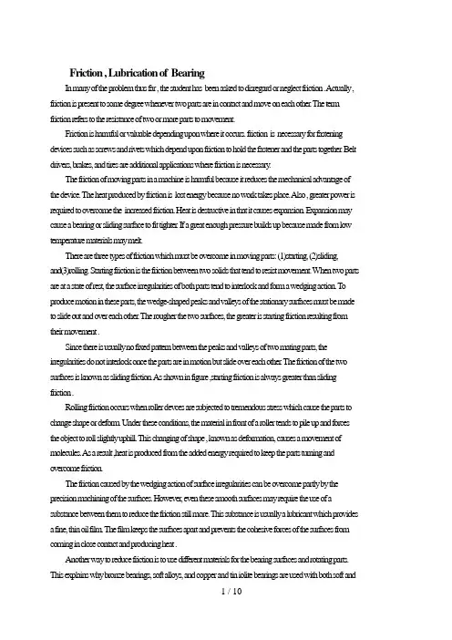
Friction , Lubrication of BearingIn many of the problem thus far , the student has been asked to disregard or neglect friction . A ctually , friction is present to some degree whenever two parts are in contact and move on each other. The term friction refers to the resistance of two or more parts to movement.Friction is harmful or valuable depending upon where it occurs. friction is necessary for fastening devices such as screws and rivets which depend upon friction to hold the fastener and the parts together. Belt drivers, brakes, and tires are additional applications where friction is necessary.The friction of moving parts in a machine is harmful because it reduces the mechanical advantage of the device. The heat produced by friction is lost energy because no work takes place. A lso , greater power is required to overcome the increased friction. Heat is destructive in that it causes expansion. Expansion may cause a bearing or sliding surface to fit tighter. If a great enough pressure builds up because made from low temperature materials may melt.There are three types of friction which must be overcome in moving parts: (1)starting, (2)sliding,and(3)rolling. Starting friction is the friction between two solids that tend to resist movement. When two parts are at a state of rest, the surface irregularities of both parts tend to interlock and form a wedging action. T o produce motion in these parts, the wedge-shaped peaks and valleys of the stationary surfaces must be made to slide out and over each other. The rougher the two surfaces, the greater is starting friction resulting from their movement .Since there is usually no fixed pattern between the peaks and valleys of two mating parts, the irregularities do not interlock once the parts are in motion but slide over each other. The friction of the two surfaces is known as sliding friction. A s shown in figure ,starting friction is always greater than sliding friction .Rolling friction occurs when roller devces are subjected to tremendous stress which cause the parts to change shape or deform. Under these conditions, the material in front of a roller tends to pile up and forces the object to roll slightly uphill. This changing of shape , known as deformation, causes a movement of molecules. As a result ,heat is produced from the added energy required to keep the parts turning and overcome friction.The friction caused by the wedging action of surface irregularities can be overcome partly by the precision machining of the surfaces. However, even these smooth surfaces may require the use of a substance between them to reduce the friction still more. This substance is usually a lubricant which provides a fine, thin oil film. The film keeps the surfaces apart and prevents the cohesive forces of the surfaces from coming in close contact and producing heat .Another way to reduce friction is to use different materials for the bearing surfaces and rotating parts. This explains why bronze bearings, soft alloy s, and copper and tin iolite bearings are used with both soft andhardened steel shaft. The iolite bearing is porous. Thus, when the bearing is dipped in oil, capillary action carries the oil through the spaces of the bearing. This type of bearing carries its own lubricant to the points where the pressures are the greatest.Moving parts are lubricated to reduce friction, wear, and heat. The most commonly used lubricants are oils, greases, and graphite compounds. Each lubricant serves a different purpose. The conditions under which two moving surfaces are to work determine the type of lubricant to be used and the system selected for distributing the lubricant.On slow moving parts with a minimum of pressure, an oil groove is usually sufficient to distribute the required quantity of lubricant to the surfaces moving on each other .A second common method of lubrication is the splash system in which parts moving in a reservoir of lubricant pick up sufficient oil which is then distributed to all moving parts during each cycle. This system is used in the crankcase of lawn-mower engines to lubricate the crankshaft, connecting rod ,and parts of the piston.A lubrication system commonly used in industrial plants is the pressure system. In this system, a pump on a machine carries the lubricant to all of the bearing surfaces at a constant rate and quantity.There are numerous other sy stems of lubrication and a considerable number of lubricants available for any given set of operating conditions. Modern industry pays greater attention to the use of the proper lubricants than at previous time because of the increased speeds, pressures, and operating demands placed on equipment and devices.Although one of the main purposes of lubrication is reduce friction, any substance-liquid , solid , or gaseous-capable of controlling friction and wear between sliding surfaces can be classed as a lubricant.V arieties of lubricationUnlubricated sliding. Metals that have been carefully treated to remove all foreign materials seize and weld to one another when slid together. In the absence of such a high degree of cleanliness, adsorbed gases, water vapor ,oxides, and contaminants reduce frictio9n and the tendency to seize but usually result in severe wear。
机械设计过程外文文献翻译、中英文翻译
附录英文Machine design processThe machine is the organization with other components combinations, transforms,the transmission or using the energ,the strength or the movementexample for the beneficial use has the engine.the turbine wheel,the vehicles.the hoist,the printer,the washer and the movie camera Many is suitable tbr themachine design principle and the strength law also is suitable to is not thegenuine machine finished product.the driven wheel hub and the file cabinet tothe measuring appl iance and the nuclear pressure vessel.”Machine designt thisterminology compared to”machine design”more generalized,it including machine design.But regarding certain instruments.1ike uses to determine hot,the mobile line and the volume thermal energy as well as the fluid aspect question needs alone to consider.But when machine design must consider themovement and the structure aspect question as well as preserved and the sealstipulation.In the mechanical engineering domain and all that project domainapplication machine design,all need such as mechanism and so on the svdtch,cam,valve,vessel and mixer.The design beginning tO being true or the imagination need.The existing instrument possibly needs in the durability,the efficiency,the weight,the speedor the cost performs to improve.]he possible need new instrument tO completebefore made the function by the person.1ike t was abundant Assembly or maintenance.After the goal completely or partially determines,the design nextstep is the idea carl complete needs the ffmction the organization and its thearrangement for this,the free hand drawing schematic diagram value is enormous,it not only takes a person idea the recording and the auxiliary.methodwhich if the other people discusses,moreover especially is suitable for with ownidea exchange,also needs to concern as the creative mentality stimulant to thepart widespread knowledge,because a new machine frequently by knew very well each kind of components rearrange or the replace become,perhaps changedthe size and the material.Regardless of after idea process or,a designer callcarry on fast either the sketchy computation or the analysis determines thegeneral size and the feasibility.After about need or may use the spatial meteidea determination,may start according to the proportion picture schematicdiagram.When several components approximate shapes and several sizes come out,the analysis was allowed truly to start.The analysis goal lies in enable it to havesatisfying or the superior performance,as well as will seek the best proportionand the size under the smallest weight security and the durability and thecompetitive cost designer for each essential load bearing section,as well asseveral components intensities balance then choice material and processingmethod.These important goals only have through only then may obtain based on the mechanism analysis,like about reacting force and friction most superioruse principie of statics;About inertia,acceleration and energy principle ofdynamics:About stress and deflection material elasticity and intensity principle;About material physical behavior principle;About lubrication and water poweractuation hydromechanics principle.The analysis may identical engineer whicharranges by the idea machinery do,or makes the analysis in the big company bythe independent analysis department or the research group the result,possibleneed new arrangement and new size.No matter is officially does orunofficialdoes,supposes Japan is relapse and the cooperation process.the analysis staffmay play the role to all stages but not merely is he stage.Some design criteriaIn this part,some people suggested carries on the analysis using the creative manner,this kind of analysis may cause the significant improvement aswell as to the spare product idea and the consummation,the product functionmore.more economical,is perhaps more durable. The creation stage does notneed is at first and the independent stage.Alttlough the analysis staff possiblycertainlv is not responsible for the entire design,but he not meyely is can fromthe numeral proposc wants question correct answer which he soIVes,not merelyis Droduces the stress value,the size or the work limit. He may propose a morewidespread opinion,in order to improvement standard or plan. Because beforethe analysis or in the analysis process,he can familiar install and its the workingcondition.he is in an idea to prepare chooses the plan the rantage Poinl.Best hecan propose the suggestion transfigure eliminates the moment of force or thestress concentration,but was not the permission constructs has the blgsectlonand the excessively many dynamic loads organization should better be he discards his careful desi{;n but is not afterwards saw the machinery discarded.In order to stimulate the creative thought,below suggested designs thepersonnel and the analysis staff uses the criterion.The first 6 criteria especially are suitable for the analysis staff,although he possibly involves to possesses this l o items.1.Creatively the use needs the physical performance and the control doesnot need.2.Knows the practical load and its the importance.3.D00s not consider the function load in advance.4.Invents the more advantageous loading environment.5.Provides the minimurn weight the most advantageous stress distributionand the rigidity.6.uses the fundamental equation computation proportion and causes thesize optimization.7.The selection material obtains the perlbrmance combination.8.In between spare parts and integrated components carefid choice. 9.Revisions functional design adapts the production process and reduces thecost.10.In the consideration assembly causes the part pintpointing and mutuallydoes not disturb.Designs the personnel to have in such domain,like the statics,the inematics,dynamics and the materials mechanics have the good accomplishment,in addition.but also must familiar make the material and themanufacture craft.Designs the personnel to have to be able to combine allcollrelations the fact,carries on teaches Wei.the manufacture schematic diagramand the charting comes the manufacture request totransmit the workshop. Any product design one of first step of work is the choice uses in to makeeach part the material.Today design personnel may obtain innumerably.When choice,the product function,the outward appearance,the material cost and theproduction cost very are all important.Before any computation must carefullyappraise the material the performance.It is the necessary careful computation toguarantee the design the validity The computation ever does not appear on thechart,but is saved by ten each kind of reason.Once any part expires,had makeclear when is designing at first this had the flaw the components has made any;Moreover,。
机械设计制造及其自动化毕业设计外文翻译

机械设计制造及其自动化毕业设计外文翻译英文原文名Automatic production line PLC control of automatic feeding station中文译名基于PLC的自动化生产线自动上料站的控制中文译文:自动化生产线自动上料站的PLC控制自动生产线是由工件传送系统和控制系统,将一组自动机床和辅助设备按照工艺顺序联结起来,自动完成产品全部或部分制造过程的生产系统,简称自动线。
二十世纪20年代,随着汽车、滚动轴承、小电机和缝纫机和其他工业发展,机械制造业开始出现在自动生产线,第一个是组合机床自动线。
在20世纪20年代,第一次出现在汽车工业流水生产线和半自动生产线,然后发展成自动生产线。
第二次世界大战后,在机械制造工业发达国家,自动生产线的数量急剧增加。
采用自动生产线生产的产品应该足够大,产品设计和技术应该是先进的、稳定的和可靠的,基本上保持了很长一段时间维持不变。
自动线用于大,大规模生产可以提高劳动生产率,稳定和提高产品质量,改善劳动条件,降低生产区域,降低生产成本,缩短生产周期,保证生产平衡、显著的经济效益。
自动生产线的一个干预指定的程序或命令自动操作或控制的过程,我们的目标是稳定、准确、快速。
自动化技术广泛用于工业、农业、军事、科学研究、交通运输、商业、医疗、服务和家庭,等自动化生产线不仅可以使人们从繁重的体力劳动、部分脑力劳动以及恶劣、危险的工作环境,能扩大人的器官功能,极大地提高劳动生产率,提高人们认识世界的能力,可以改变世界。
下面我说下它的应用范围:机械制造业中有铸造、锻造、冲压、热处理、焊接、切削加工和机械装配等自动线,也有包括不同性质的工序,如毛坯制造、加工、装配、检验和包装等的综合自动线。
加工自动线发展最快,应用最广泛的机械制造。
主要包括:用于处理盒、外壳、各种各样的部件,如组合机床自动线;用于加工轴、盘部分,由通用、专业化、或自动机器自动专线;转子加工自动线;转子自动线加工过程简单、小零件等。
机械类外文文献及翻译
机械类外文文献及翻译(文档含中英文对照即英文原文和中文翻译)原文:GEAR AND SHAFT INTRODUCTIONAbstract:The important position of the wheel gear and shaft can't falter in traditional machine and modern machines.The wheel gear and shafts mainly install the direction that delivers the dint at the principal axis box. The passing to process to make them can is divided into many model numbers, using for many situations respectively. So we must be the multilayers to the understanding of the wheel gear and shaft in many ways .Key words: Wheel gear; ShaftIn the force analysis of spur gears, the forces are assumed to act in a single plane. We shall study gears in which the forces have three dimensions. The reason for this, in the case of helical gears, is that the teeth are not parallel to the axis of rotation. And in the case ofbevel gears, the rotational axes are not parallel to each other. There are also other reasons, as we shall learn.Helical gears are used to transmit motion between parallel shafts. The helix angle is the same on each gear, but one gear must have a right-hand helix and the other a left-hand helix. The shape of the tooth is an involute helicoid. If a piece of paper cut in the shape of a parallelogram is wrapped around a cylinder, the angular edge of the paper becomes a helix. If we unwind this paper, each point on the angular edge generates an involute curve. The surface obtained when every point on the edge generates an involute is called an involute helicoid.The initial contact of spur-gear teeth is a line extending all the way across the face of the tooth. The initial contact of helical gear teeth is a point, which changes into a line as the teeth come into more engagement. In spur gears the line of contact is parallel to the axis of the rotation; in helical gears, the line is diagonal across the face of the tooth. It is this gradual of the teeth and the smooth transfer of load from one tooth to another, which give helical gears the ability to transmit heavy loads at high speeds. Helical gears subject the shaft bearings to both radial and thrust loads. When the thrust loads become high or are objectionable for other reasons, it may be desirable to use double helical gears. A double helical gear (herringbone) is equivalent to two helical gears of opposite hand, mounted side by side on the same shaft. They develop opposite thrust reactions and thus cancel out the thrust load. When two or more single helical gears are mounted on the same shaft, the hand of the gears should be selected so as to produce the minimum thrust load.Crossed-helical, or spiral, gears are those in which the shaft centerlines are neither parallel nor intersecting. The teeth of crossed-helical fears have point contact with each other, which changes to line contact as the gears wear in. For this reason they will carry out very small loads and are mainly for instrumental applications, and are definitely not recommended for use in the transmission of power. There is on difference between a crossed heli : cal gear and a helical gear until they are mounted in mesh with each other. They are manufactured in the same way. A pair of meshed crossed helical gears usually have the same hand; that is ,a right-hand driver goes with a right-hand driven. In the design of crossed-helical gears, the minimum sliding velocity is obtained when the helix angle areequal. However, when the helix angle are not equal, the gear with the larger helix angle should be used as the driver if both gears have the same hand.Worm gears are similar to crossed helical gears. The pinion or worm has a small number of teeth, usually one to four, and since they completely wrap around the pitch cylinder they are called threads. Its mating gear is called a worm gear, which is not a true helical gear. A worm and worm gear are used to provide a high angular-velocity reduction between nonintersecting shafts which are usually at right angle. The worm gear is not a helical gear because its face is made concave to fit the curvature of the worm in order to provide line contact instead of point contact. However, a disadvantage of worm gearing is the high sliding velocities across the teeth, the same as with crossed helical gears.Worm gearing are either single or double enveloping. A single-enveloping gearing is onein which the gear wraps around or partially encloses the worm.. A gearing in which each element partially encloses the other is, of course, a double-enveloping worm gearing. The important difference between the two is that area contact exists between the teeth of double-enveloping gears while only line contact between those of single-enveloping gears. The worm and worm gear of a set have the same hand of helix as for crossed helical gears, but the helix angles are usually quite different. The helix angle on the worm is generally quite large, and that on the gear very small. Because of this, it is usual to specify the lead angle on the worm, which is the complement of the worm helix angle, and the helix angle on the gear; the two angles are equal for a 0-deg. Shaft angle.When gears are to be used to transmit motion between intersecting shaft, some of bevel gear is required. Although bevel gear are usually made for a shaft angle of 0 deg. They may be produced for almost any shaft angle. The teeth may be cast, milled, or generated. Only the generated teeth may be classed as accurate. In a typical bevel gear mounting, one of the gear is often mounted outboard of the bearing. This means that shaft deflection can be more pronounced and have a greater effect on the contact of teeth. Another difficulty, which occurs in predicting the stress in bevel-gear teeth, is the fact the teeth are tapered.Straight bevel gears are easy to design and simple to manufacture and give very good results in service if they are mounted accurately and positively. As in the case of squr gears, however, they become noisy at higher values of the pitch-line velocity. In these cases it is often go : od design practice to go to the spiral bevel gear, which is the bevel counterpart of thehelical gear. As in the case of helical gears, spiral bevel gears give a much smoother tooth action than straight bevel gears, and hence are useful where high speed are encountered.It is frequently desirable, as in the case of automotive differential applications, to have gearing similar to bevel gears but with the shaft offset. Such gears are called hypoid gears because their pitch surfaces are hyperboloids of revolution. The tooth action between such gears is a combination of rolling and sliding along a straight line and has much in common with that of worm gears.A shaft is a rotating or stationary member, usually of circular cross section, having mounted upon it such elementsas gears, pulleys, flywheels, cranks, sprockets, and other power-transmission elements. Shaft may be subjected to bending, tension, compression, or torsional loads, acting singly or in combination with one another. When they are combined, one may expect to find both static and fatigue strength to be important design considerations, since a single shaft may be subjected to static stresses, completely reversed, and repeated stresses, all acting at the same time.The word “shaft” covers numerous v ariations, such as axles and spindles. Anaxle is a shaft, wither stationary or rotating, nor subjected to torsion load. A shirt rotating shaft is often called a spindle.When either the lateral or the torsional deflection of a shaft must be held to close limits, the shaft must be sized on the basis of deflection before analyzing the stresses. The reason for this is that, if the shaft is made stiff enough so that the deflection is not too large, it is probable that the resulting stresses will be safe. But by no means should the designer assume that they are safe; it is almost always necessary to calculate them so that he knows they are within acceptable limits. Whenever possible, the power-transmission elements, such as gears or pullets, should be located close to the supporting bearings, This reduces the bending moment, and hence the deflection and bending stress.Although the von Mises-Hencky-Goodman method is difficult to use in design of shaft, it probably comes closest to predicting actual failure. Thus it is a good way of checking a shaft that has already been designed or of discovering why a particular shaft has failed in service. Furthermore, there are a considerable number of shaft-design problems in which the dimension are pretty well limited by other considerations, such as rigidity, and it is only necessary for the designer to discover something about the fillet sizes, heat-treatment,and surface finish and whether or not shot peening is necessary in order to achieve the required life and reliability.Because of the similarity of their functions, clutches and brakes are treated together. In a simplified dynamic representation of a friction clutch, or brake, two in : ertias I and I traveling at the respective angular velocities W and W, one of which may be zero in the case of brake, are to be brought to the same speed by engaging the clutch or brake. Slippage occurs because the two elements are running at different speeds and energy is dissipated during actuation, resulting in a temperature rise. In analyzing the performance of these devices we shall be interested in the actuating force, the torque transmitted, the energy loss and the temperature rise. The torque transmitted is related to the actuating force, the coefficient of friction, and the geometry of the clutch or brake. This is problem in static, which will have to be studied separately for eath geometric configuration. However, temperature rise is related to energy loss and can be studied without regard to the type of brake or clutch because the geometry of interest is the heat-dissipating surfaces. The various types of clutches and brakes may be classified as fllows:. Rim type with internally expanding shoes. Rim type with externally contracting shoes. Band type. Disk or axial type. Cone type. Miscellaneous typeThe analysis of all type of friction clutches and brakes use the same general procedure. The following step are necessary:. Assume or determine the distribution of pressure on the frictional surfaces.. Find a relation between the maximum pressure and the pressure at any point. Apply the condition of statical equilibrium to find (a) the actuating force, (b) the torque, and (c) the support reactions.Miscellaneous clutches include several types, such as the positive-contact clutches, overload-release clutches, overrunning clutches, magnetic fluid clutches, and others.A positive-contact clutch consists of a shift lever and two jaws. The greatest differences between the various types of positive clutches are concerned with the design of the jaws. To provide a longer period of time for shift action during engagement, the jaws may be ratchet-shaped, or gear-tooth-shaped. Sometimes a great many teeth or jaws are used, and they may be cut either circumferentially, so that they engage by cylindrical mating, or on the faces of the mating elements.Although positive clutches are not used to the extent of the frictional-contact type, they do have important applications where synchronous operation is required.Devices such as linear drives or motor-operated screw drivers must run to definite limit and then come to a stop. An overload-release type of clutch is required for these applications. These clutches are usually spring-loaded so as to release at a predetermined toque. The clicking sound which is heard when the overload point is reached is considered to be a desirable signal.An overrunning clutch or coupling permits the driven member of a machine to “freewheel” or “overrun” bec ause the driver is stopped or because another source of power increase the speed of the driven. This : type of clutch usually uses rollers or balls mounted between an outer sleeve and an inner member having flats machined around the periphery. Driving action is obtained by wedging the rollers between the sleeve and the flats. The clutch is therefore equivalent to a pawl and ratchet with an infinite number of teeth.Magnetic fluid clutch or brake is a relatively new development which has two parallel magnetic plates. Between these plates is a lubricated magnetic powder mixture. An electromagnetic coil is inserted somewhere in the magnetic circuit. By varying the excitation to this coil, the shearing strength of the magnetic fluid mixture may be accurately controlled. Thus any condition from a full slip to a frozen lockup may be obtained.齿轮和轴的介绍摘要:在传统机械和现代机械中齿轮和轴的重要地位是不可动摇的。
机械设计类英文文献及翻译
The Sunflower Seed Huller and Oil PressBy Jeff Cox-- from Organic Gardening, April 1979, Rodale PressIN 2,500 SQUARE FEET, a family of four can grow each year enough sunflower seed to produce three gallons of homemade vegetable oil suitable for salads or cooking and 20 pounds of nutritious, dehulled seed -- with enough broken seeds left over to feed a winter's worth of birds.The problem, heretofore, with sunflower seeds was the difficulty of dehulling them at home, and the lack of a device for expressing oil from the seeds. About six months ago, we decided to change all that. The job was to find out who makes a sunflower seed dehuller or to devise one if none were manufactured. And to either locate a home-scale oilseed press or devise one. No mean task.Our researches took us from North Dakota -- hub of commercial sunflower activity in the nation -- to a search of the files in the U.S. Patent Office, with stops in between. We turned up a lot of big machinery, discovered how difficult it is to buy really pure, unrefined vegetable oils, but found no small-scale equipment to dehull sunflowers or press out their oil. The key to success, however, was on our desk the whole time. In spring 1977, August Kormier had submitted a free-lance article describing how he used a Corona grain mill to dehull his sunflower seeds, and his vacuum cleaner exhaust hose to blow the hulls off the kernels. A second separation floated off the remaining hulls, leaving a clean product. We'd tried it, but because some kernels were cracked and the process involved drying, we hadn't been satisfied. Now we felt the best approach was to begin again with what we learned from Mr. Kormier and refine it.Staff Editor Diana Branch and Home Workplace Editor Jim Eldon worked with a number of hand- and electric-powered grain mills. While the Corona did a passable job, they got the best results with the C.S. Bell #60 hand mill and the Marathon Uni Mill, which is motor-driven. "I couldn't believe my eyes the first time I tried the Marathon," Diana says. "I opened the stones to 1/8th inch, and out came a bin full of whole kernels and hulls split right at the seams. What a thrill that was!"She found that by starting at the widest setting,and gradually narrowing the opening, almost every seed was dehulled. The stones crack the hulls open, then rub them to encourage the seed away from the fibrous lining. The Bell hand mill worked almost as well. "As long as the stones open at least as wide as the widest unhulled seed, any mill will work," she says.Because the seed slips through the mill on its flat side, grading is an important step to take before dehulling. We made three sizing boxes. Thefirst is 1/4-inch hardware cloth [wire screen]. The second is two layers of1/4-inch cloth, moved slightly apart to narrow the opening in one direction, and the third is two layers of screen adjusted to make a still-smaller opening. Since the smallest unhulled seeds are about the size of the largest hulled kernels, the grading step prevents these undersized seeds from passing through unhulled. Processed together at a closer setting, the smallest seeds hulled out.Jim Eldon's workshop is littered with strange-looking pieces of apparatus. They represent initial attempts to build a workable winnowing box, using Kormier's vacuum exhaust idea for a source of air. Jim, Fred Matlack and Diana finally made a box with a Plexiglas front, through which they could observe what was happening.They cut a hole in the back of the box with a sliding cover to regulate the air pressure, and fiddled with various arrangements of baffles. The result was a stream of hulls exiting through one hole while the kernels fell to the bottom of the box. Now they were ready to try a five-pound sample of unhulled sunflower seeds to see how much they could recover.The five pounds were graded and dehulled, then winnowed. We got about one hull for every ten kernels in the final, winnowed product. These are easily picked out. They usually contain kernels still held behind the fibrous strings of the hull. Their weight prevents them from blowing out with the empty hulls. We found that bug-eaten seeds do blow away with the chaff, which was a bonus for cleanliness of the final product. Toss the hulls to the birds, who will find broken seeds among them.Starting with 80 ounces of unhulled seed, we ended up with 41-1/4 ounces of edible whole seeds, 1.8 ounces of damaged seeds suitable for animal feed, and 36.6 ounces of hulls. It took us about an hour. Notbad.Sunflower seeds store perfectly in the hulls, but they deteriorate more rapidly when shelled out. The grain mill dehuller and winnowing box give the gardener a way to have the freshest possible seeds for eating at all times of the year. With the construction of one more piece of equipment -- the oil press -- he can have absolutely fresh, unrefined, polyunsaturated sunflower oil for salads, mayonnaise and cooking.Most light, refined vegetable oils have been extracted using hexane, a form of naphtha. The oil is then heated to boil off the hexane. Lye is dumped into it. It's washed with steam, then heated to remove odors and taste before being laced with preservatives and stabilizers. It may feel oily in the mouth, but you might as well taste air. No so with fresh-made sunflower oil -- it's deliciously yet subtly nutty in flavor, adding unsurpassed flavor to salads.There's good reason to believe that sunflower oil may become the #1 vegetable oil in the U.S. in a few years. It's already #1 in health-conscious Europe. Corn oil has already caught on here for health reasons, and sunflower oil is so much better. Sunflower oil's 70 percent polyunsaturate is just under safflower, with corn oil bringing up the rear with 55 percent. And sunflowers yield 40 percent oil, soybeans only 20 percent.Our oil press isrelatively simple, but it must be welded together. Check the construction directions for details. The press consists of a welded tubular frame which accepts a three-ton hydraulic jack. You may already have one. If not, it can be purchased at most auto and hardware stores for about $16. A metal canister with holes drilled in its sides and one end welded shut holds the mashed sunflower seeds. A piston is inserted in the canister and then inverted and slipped over a pedestal on the frame. The jack is set in place, and the pressure gradually increased over half an hour. The oil drips from the sides of the canister into a tray -- the bottom of a plastic jug slipped over the pedestal works fine -- which empties the oil into a cup. You can filter the oil with a coffee filter to remove pieces of seed and other fine particles that would burn if the oil were used for cooking. If it's for salads or mayonnaise, there's no need to filter it.We first tried using "confectionary" sunflower seeds for oil. These are the regular eating kernels we're used to seeing. They give less than half as much oil as the oilseed types of sunflower. Although you can use confectionary types such as MAMMOTH RUS- SIAN for oil, don't expect to get more than an ounce and a half from a pound of seed. Oilseed produces three or more ounces of oil from a pound of seed and is well worth planting along with confectionary-type seeds. Oilseed has another big advantage -- to prepare it, you can put the whole, unhulled seed into a blender and whiz it until it forms a fine meal, while confectionary seeds must be dehulled first. The entire sequence of grading, dehulling and winnowing is avoided with oilseed.Oil types produce about a tenth of a pound of seed per head in commercial production. Gardeners, with their better soil and care, invariably do better than that. Our conservative estimate is that 1,280 plants will be enough for three gallons of oil. Spaced one foot apart in rows two feet apart, 1,280 oilseed plants will take a space 40-by-56 feet, or 80-by-28 if you want a more rectangular patch to face south.We worked in pound batches, since the canister just holds one pound of mash. After blending, we heated it to 170 degrees F. (77 deg C) by placing it in a 300-degree F. (149 deg C) oven and stirring it every five minutes for 20 minutes. Heating gets the oil flowing and doubles the yield of oil. In case you're wondering,"cold-pressed" oils sold commercially are also heated, and some are subjected to the entire chemical process. The term has no firm meaning within the industry, according to the literature we've surveyed.Heating does not change the structure of fats. It will not turn polyunsaturated fats into saturated fats. In fact, Dr. Donald R. Germann in his book, "TheAnti-Cancer Diet", says that "... an unsaturated fat must be heated to high temperatures -- above 425 degrees F. or 200 degrees C. -- at least 8 or 10 times before any shift toward saturation occurs..." Dean C. Fletcher, Ph.D., of the American Medical Association Department of Foods and Nutrition in Chicago, says, "It's true that either high temperature or repeated heatingdoes change the nature of some of the unsaturated oil molecules. (But) the flavor of the oil changes as these chemical changes occur, spoiling its taste. This effect is probably more profound than any of the physiological changes the altered oil might produce within the body."From 500 gm. of heated mash, we pressed 89 gm. of oil, 89 percent of the entire amount available and twice as much as we could press from unheated oil! The decision is up to you whether or not to heat the mash, but that extra 50 percent seems like an awful lot, especially when the whole technique is so labor intensive. The oil should be stored in the refrigerator, and it's probably best to use it within a month, since it has no preservatives. Mayonnaise made with such fresh oils should be kept refrigerated and used within two weeks. The leftover cake, still containing 50 percent of its oil, is a nutritious addition to your dishes, and makes excellent feed for animals or winter birds. Store the pressed cake in the freezer.We're talking then about a sunflower patch with two kinds of plants -- confectionary such as MAMMOTH RUSSIAN and oilseed such as PEREDOVIK. The oilseed plants should be grown 12 inches apart in rows two feet apart. Four average confectionary heads yield about a pound of unhulled seed. You'll need about 35 pounds of unhulled seed, or 140plants-worth, to yield 20 pounds of hulled kernels, about what a family of four will use in a year. That many plants can be grown in an area 26-by-10 feet. That's 260 square feet. Put that together with the 2,240 square feet for the oilseed sunflowers, and you need a patch about 2,500 square feet -- 25 100-foot rows -- to keep yourself supplied year-round with super nutrition and unsurpassable taste.Winnowing Machine For Sunflower SeedsThe winnowing machine operates on the age-old principle of blowing the chaff away from the heavy grain with a controlled current of air.The unit uses a household or shop-type vacuum cleaner for its air supply. A vacuum cleaner was used as a power source because it can supply a large volume of air over an extended period of time, and most homes and farms have a vacuum cleaner.A cloth bag has been attached to the chaff chute to catch the chaff as it is separated from the seed. The bag allows the hulls to be collected and greatly reduces the amount of waste material normally blown into the air by conventional systems.The unit has been constructed in such a way that the cloth bag and cleaner box can be placed inside the seed box, making a compact package for storage.Tools Required1. Table Saw2. Drill Press3. Band Saw4. Saber SawProcedure (cleaner box)1 . Cut out the two sides of the cleaner box from 1/4-inch plywood.2. Cut out the six interior pieces of the cleaner box from 3/4 x 3-1/2-inch select pine.3. Assemble the cleaner box elements with glue and nails.4. Cut four 1/4-inch square strips of pine four inches long.5. Glue the strips around the end of the chaff chute.6. Sand all surfaces and edges.7. Finish with clear lacquer finish.Procedure (seed box)1. Cut two pieces of pine /34" x 5 /12 x 15 inches for the sides.2. Cut two pieces of pine 3/4 x 5-1/2 x inches for the top and bottom.3. Plow a /14 x 1/4 groove for the front and back panels in all four pieces.4. Rip the top board to 5 inches so that the front panel can slide into the grooves in the side boards.5. Rabbet both ends of each 15-inch side piece to accept the top and bottom boards.6. Drill a hole in the left side board 2-1/2 inches from the top. The size of the hole is determined by the vacuum cleaner hose fitting.7. Cut a 3-1/4 x 4 inch hole in the top 1/2 inch from the right end. This hole will accept the cleaner box.8. Cut two pieces of pine for the baffle.9. Drill two 1-inch holes in the bottom of the baffle box.10. Cut a piece of 1/4 x 8-1/2 x 14 inch plywood for the back panel.11. Cut a 3-inch hole, centered 1-7/8 inches from the top and left sides of the plywood back.12. Assemble the sides, baffles, top, bottom, and back panel with glue and nails.13. Cut an 8-7/16 x 15-3/4-inch piece of Plexiglas for the front.14. Cut a one-inch radius on the top corners of the front.and sand the edges.15. Drill a one-inch thumb hole centered 7/8 inch from the top edge.16. Cut a 3-1/2-inch disk of 1/4-inch plywood for the vent cover.17. Drill a 3/16-inch hole 3/8 inch from the edge of the disk.18. Mount the disk over the vent with a #10 x 1-inch screw.19. Sand all surfaces and edges of the, box.20. Finish with clear lacquer finish.MaterialsCleaner Box2 -- 7-3/4 x 7-1/2 x 3/4" plywood (sides)6 -- 3/4 x 3-1/2 x 24" for all members (baffles)4 -- 1/4 x 1/4 x 4" pine (chute cleats)22 -- 1" x 18 ga. headed nailsWhite vinyl glueClear lacquer finishSeed Box2 -- 3/4' x 5-1/2 x 15" select pine (sides)2 -- 3/4 x 5-1/2 x 8-1/2" select pine (top and bottom)1 -- 3/4 x 3-1/2 x 4-1/2" select pine (baffle)1 -- 3/4 x 4-1/2 x 4-1/2" select pine (baffle)1 -- 1/4 x 8-1/2 x 14" plywood (back)1 -- 1/4 x 3-1/2" dia. plywood (control valve)1 -- 1/4' x 8-7/16 x 15-1/4" Plexiglas (front)1 - #10 x 1" flat head screw18 - 4d finish nailsWhite vinyl glueClear lacquer finish1 -- 17 x 31" cloth laundry bagSunflower Seed Oil PressThe press was designed so that homesteaders can produce sunflower oil from their own seeds. The oil can be pressed as is or heated to 170 degrees F., which doubles oil yield.Both methods require the seed to be ground to fine powder. If you are pressing the oil seed variety, a meat grinder or electric blender will do an excellent job of grinding the seed. The confectionary type of seed will require the seed to be hulled and winnowed before it is ground. A food mill with the stones set at the coarse setting can be used to accomplish this step. The ground kernels are placed in the cylinder with the piston closing the bottom portion of the cylinder.The cylinder is mounted in the press frame and a three-ton hydraulic jack is used to supply the pressure.Because of the great pressures created by the hydraulic jack, it is important that the frame be properly constructed and firmly mounted to the work surface before the pressing operation begins. The following instructions can be given to a welder.Tools Required1. Power Hacksaw2. Metal Band Saw3. Metal Lathe4. Drill Press5. Belt or Disk Grinder6. Arc Welder7. Hand ClampsProcedure (Frame)1. Cut two pieces of 1-3/4" O.D. x 1-3/8" I.D. x 24-1/2 inch long tubing for the uprights.2. Cut one piece of 1-3/4" O.D. x 1-3/8" I.D. x 6-1/2 inch long tubing for the center tube.3. Cut one 3/4" x 2-3/4 x 5-1/2 inch steel bar for the top cross member.4. Cut two pieces of 1-3/4 x 1-3/4 x 8 inch angle iron for the base members.5. Drill two 9/32-inch holes in each base member 1/2 inch from the outer edges.6. Weld the base members, tubes and cross member together as per the drawing.7. Grind all edges to remove any burrs.8. Paint the frame.9. If a mounting board is desired, cut a piece of pine 1-1/4 x 6-1/2 x 12 inches long.10. Center the frame on the board and mark the location of the four mounting holes.11. Drill four 7/8-inch holes 1/4-inch deep to accept the T-nuts.12. Drill four 5/16-inch holes through the mounting board using the same centers created by the 7/8-inch holes.13. Round the edges of the base and sand all surfaces.14. Install four 1/4-20 T-nuts.15. Finish the base with clear lacquer finish.16. Assemble the base to the frame using four 1/4-20 x 1-1/4-inch round head bolts.Procedure (Cylinder)1. Cut a piece of 3-1/2" O.D. x 3-1/4" I.D. tubing 5-3/8 inches long.2. Face both ends on the lathe.3. Cut out a 3-1/2-inch round disk from 1/4-inch plate steel.4. Weld the disk to one end of the tube.5. Drill a series of 3/32-inch holes around the side of the tube on 1/2-inch centers.6. Remove all burrs on the inside and outside of the tube.Procedure (Piston)1. Cut out a 3-3/8-inch disk of 1/4-inch plate steel.2. Cut a 1-3/8" O.D. x 1-1/8" I.D. piece of tubing 1-1/8 inches long.3. Face both ends of the tube.4. Weld the tube in the center of the 3-3/8-inch disk. All welds should be made on the inside of the tube.5. Mount the piston in the lathe and turn the disk to fit the inside diameter of the cylinder. This will be about 3-15/64 inches in diameter.6. Remove any sharp edges.Procedure (Collector Ring)1. Cut the bottom out of a one-gallon plastic bottle. The cut line should be approximately 1-1/2 inches from the bottom of the bottle.2. Make a 1/8 x 1 inch slot at one edge of the bottom outside ring. This will allow the oil to pour into a receiving cup.3. Cut a 1-3/4-inch hole in the center of the bottom, so that the unit will fit over the center tube in the frame.MaterialsFrame2 -- 1-3/4 O.D. x 1-3/8 I.D. x 24-1/2" long H.R.S. (frame tubes)1 -- 1-3/4 O.D. x 1-3/8 I.D. x 6-1/2 inch long H.R.S. (center tube)1 -- 3/4 x 2-3/4 x 5-1/2" flat bar H.R.S. (top cross member)2 -- 1-3/4 x 1-3/4 x 8" angle iron H.R.S. (base members)1 -- 1-1/4 x 6-1/2 x 12" #2 white pine (wood base)4 -- 1/4-20 x 1-1/4 R.H. mounting bolts4 -- 1/4-20 T-nutsBlack enamel for frame (finishing material)Clear lacquer finish for wood base3 -- 1/8" dia. welding rodsCylinder1 -- 1/4 x 3-1/2" dia. C.R.S. disk (top)1 -- 3-1/2 O.D. x 3-1/4 I.D. C.R.S. tube (cylinder)1 -- 1/8 dia. welding rodPiston1 -- 1/4 x 3-3/8 D.A. C.R.S. disk (piston top)1 -- 1-1/4 O.D. x 1 I.D. x 1" long H.R.S. (piston tube)1 -- 1/8 dia. welding rodCollector Ring1 -- Bottom from a one-gallon plastic bottle (oil collector ring)葵花籽脱壳机和油压机由Jeff考克斯-从有机园艺,1979年4月,罗代尔新闻2,500平方尺,一个四口之家每年可以长到足以产生三种葵花籽国产蔬菜沙拉或烹调油和20磅的营养丰富,适合脱皮加仑种子 - 与遗留养活一个冬天的产值,破碎的种子鸟类。
机械设计制造及其自动化专业外文翻译--机器人
外文原文RobotsThe industrial robot is used in the manufacturing environment to increase productivity . It can be used to do routine and tedious assembly line jobs , or it can perform jobs that might be hazardous to do routine and tedious assembly line jobs , or it can perform jobs that might be hazardous to the human worker . For example , one of the first industrial robots was used to replace the nuclear fuel rods in nuclear power plants . A human doing this job might be exposed to harmful amounts of radiation . The industrial robot can also operate on the assembly line , putting together small components , such as placing electronic components on a printed circuit board . Thus , the human worker can be relieved of the routine operation of this tedious task . Robots can also be programmed to defuse bombs , to serve the handicapped , and to perform functions in numerous applications in our society .The robot can be thought of as a machine that will move an end-of-arm tool , sensor , and gripper to a preprogrammed location . When the robot arrives at this location , it will perform some sort of task . This task could be welding , sealing , machine loading , machine unloading , or a host of assembly jobs . Generally , this work can be accomplished without the involvement of a human being , except for programming and for turning the system on and off .The basic terminology of robotic systems is introduced in the following :1. A robot is a reprogrammable , multifunctional manipulator designed to move parts , materials , tools , or special devices through variable programmed motions for the performance of a variety of different task . This basic definition leads to other definitions , presented in the following paragraphs , that give a complete picture of a robotic system .2. Preprogrammed locations are paths that the robot must follow to accomplish work . At some of these locations , the robot will stop and perform some operation , such as assembly of parts , spray painting , or welding . These preprogrammed locations are stored in the robot’s memory and are recalled later for continuous operation . Furthermore , these preprogrammed locations , as well as other program data , can be changed later as the work requirements change . Thus , with regard to this programming feature , an industrial robot is very much like a computer , where data can be stored and later recalled and edited .3. The manipulator is the arm of the robot . It allows the robot to bend , reach ,and twist . This movement is provided by the mani pulator’s axes , also called the degrees of freedom of the robot . A robot can have from 3 to 16 axes . The term degrees of freedom of freedom will always relate to the number of axes found on a robot .4. The tooling and grippers are not part of the robotic system itself ; rather , they are attachments that fit on the end of the robot’s arm . These attachments connected to the end of the robot’s arm allow the robot to lift parts , spot-weld , paint , arc-weld , drill , deburr , and do a variety of tasks , depending on what is required of the robot .5. The robotic system can also control the work cell of the operating robot . the work cell of the robot is the total environment in which the robot must perform its task . Included within this cell may be the controller , the robot manipulator , a work table , safety features , or a conveyor . All the equipment that is required in order for the robot to do its job is included in the work cell . In addition , signals from outside devices can communicate with the robot in order to tell the robot when it should assemble parts , pick up parts , or unload parts to a conveyor .The robotic system has three basic components : the manipulator , the controller , and the power source .A . ManipulatorThe manipulator , which does the physical work of the robotic system , consists of two sections : the mechanical section and the attached appendage . The manipulator also has a base to which the appendages are attached . Fig.1 illustrates the connection of the base and the appendage of a robot .The base of the manipulator is usually fixed to the floor of the work area . Sometimes , though , the base may be movable . In this case , the base is attached to either a rail or a track , allowing the manipulator to be moved from one location to another .As mentioned previously , the appendage extends from the base of the robot . The appendage is the arm of the robot . It can be either a straight , movable arm or a jointed arm . the jointed arm is also known as an articulated arm .The appendages of the robot manipulator give the manipulator its various axes of motion . These axes are attached to a fixed base , which , in turn , is secured to a mounting . This mounting ensures that the manipulator will remain in one location。
机械设计制造及其自动化 英文
机械设计制造及其自动化英文Mechanical Design, Manufacturing and AutomationMechanical design, manufacturing, and automation are essential components of the modern industrial economy. These fields encompass the creation and production of a wide variety of products, from consumer goods to high-tech machinery.In mechanical design, engineers utilize computer-aided design (CAD) software to develop and optimize the design of mechanical components and systems. This allows for the creation of precise and efficient designs that can be easily modified and tested before production begins.Once the design phase is complete, manufacturing processes take over to bring the design to life. This involves a combination of traditional machining techniques and advanced manufacturing technologies such as 3D printing and robotic assembly. The goal of manufacturing is to efficiently produce high-quality products at scale, while minimizing waste and cost.Automation plays a crucial role in both the design and manufacturing phases. Automated systems and robotics are widely used to streamline production processes, increase precision, and improve overall efficiency. This can include automated assembly lines, robotic machining, and computer-controlled quality control systems.Overall, the integration of mechanical design, manufacturing, and automation has revolutionized the way products are created andproduced. By leveraging the latest technologies and technical expertise, businesses are able to innovate and bring new productsto market more quickly and efficiently than ever before.当今的机械设计、制造和自动化技术也在不断创新。
机械加工外文翻译、中英文翻译、机械类外文文献翻译
机械加工外文翻译、中英文翻译、机械类外文文献翻译The engine lathe is an old but still useful metal removal machine with many desirable attributes。
While it is no longer commonlyXXX。
In today's n shops。
it has largely been XXX。
turret lathes。
and automatic XXX of single-point tooling for maximum metal removal。
and the use of form tools for finished products that are on par with the fastest processing XXX.When it XXX for the engine lathe。
it largely depends on the skill of the operator。
Design XXX part for n。
it is XXX.XXX cutting tools。
XXX ns。
as the machine can perform these ns in one setup。
They are also capable of producing parts with high n and accuracy。
XXX industries.Now more than ever。
n machining XXX of a specific method。
the XXX.When designing for low quantities。
such as 100 or 200 parts。
it is most cost-effective to use a XXX。
designers should aim to minimize the number of ns required.Another n for n XXX。
- 1、下载文档前请自行甄别文档内容的完整性,平台不提供额外的编辑、内容补充、找答案等附加服务。
- 2、"仅部分预览"的文档,不可在线预览部分如存在完整性等问题,可反馈申请退款(可完整预览的文档不适用该条件!)。
- 3、如文档侵犯您的权益,请联系客服反馈,我们会尽快为您处理(人工客服工作时间:9:00-18:30)。
普通钻床改造为多轴钻床
目前,我国中、小型企业的产品质量和生产效率都需要有一个新的提高, 但是加工手段却远远不能满足需要, 许多中小型企业都结合自己的实际对设备的技术状态进行改进,通过强化自身, 以求自我发展普通钻床为单轴机床,但安装上多轴箱就会成为多轴的钻床,改造成多轴钻床后,能大大地缩短加工时间,提高生产效率。
多轴加工应用:据统计,一般在车间中普通机床的平均切削时间很少超过全部工作时间的15%。
其余时间是看图、装卸工件、调换刀具、操作机床、测量以及清除铁屑等等。
使用
数控机床虽然能提高85%,但购置费用大。
某些情况下,即使生产率高,但加工相同的零件,其成本不一定比普通机床低。
故必须更多地缩短加工时间。
不同的加工方法有不同的特点,就钻削加工而言,多轴加工是一种通过少量投资来提高生产率的有效措施。
多轴加工优势:虽然不可调式多轴头在自动线中早有应用,但只局限于大批量生产。
即使采用可调式多轴头扩大了使用范围,仍然远不能满足批量小、孔型复杂的要求。
尤其随着工业的发展,大型复杂的多轴加工更是引人注目。
例如原子能发电站中大型冷凝器水冷壁管板有15000个“ 20孔,若以摇臂钻床加工,单单钻孔与锪沉头孔就要842.5小时,另外还要
划线工时151.1 小时。
但若以数控八轴落地钻床加工,钻锪孔只要171.6 小时,划线也简单,只要1.9 小时。
因此,利用数控控制的二个坐标轴,使刀具正确地对准加工位置,结合多轴加工不但可以扩大加工范围,而且在提高精度的基础上还能大大地提高工效,迅速地制造出原来不易加工的零件。
有人分析大型高速柴油机30 种箱形与杆形零件的2000 多个钻孔操作中,有40%可以在自动更换主轴箱机床中用二轴、三轴或四轴多轴头加工,平均可减少20%的加工时间。
1975年法国巴黎机床展览会也反映了多轴加工的使用愈来愈多这一趋势。
多轴加工的设备:多轴加工是在一次进给中同时加工许多孔或同时在许多相同或不同工件上各加工一个
孔。
这不仅缩短切削时间,提高精度,减少装夹或定位时间,并且在数控机
床中不必计算坐标,减少字块数而简化编程。
它可以采用以下一些设备进行加工:立钻或摇臂钻上装多轴头、多轴钻床、多轴组合机床心及自动更换主轴箱机床。
甚至可以通过二个能
自动调节轴距的主轴或多轴箱,结合数控工作台纵横二个方向的运动,加工各种圆形或椭圆
形孔组的一个或几个工序。
现在就这方面的现状作一简介。
多轴头:从传动方式来说主要有齿轮传动与万向联轴节传动二种。
这是大家所熟悉的。
前者效率较高,结构简单,后者易于调整轴距。
从结构来说有不可调式与可调式二种。
前者轴距不能改变,多采用齿轮传动,仅适用于大批量生产。
为了扩大其赞许适应性,发展了可调式多轴头,在一定范围内可调整轴距。
它主要装在有万向. 二种。
(1)万向轴式也有二种: 具有对准装置的主轴。
主轴装在可调支架中,而可调支架能在壳体的T 形槽中移动,并能在对准的位置以螺栓固定。
(2)具有公差的圆柱形主轴套。
主轴套固定在与式件孔型相同的模板中。
前一种适用于批量小且孔组是规则分布的工件(如孔组分布在不同直径的圆周上)后一种适用于批量较大式中小批量的轮番生产中,刚性较好,孔距精度亦高,但不同孔型需要不同的模板。
多轴头可以装在立钻式摇臂钻床上,按钻床本身所具有的各种功能进行工作。
这种多轴加工方法,由于钻孔效率、加工范围及精度的关系,使用范围有限。
多轴箱:也象多轴头那样作为标准部件生产。
美国Secto 公司标准齿轮箱、多轴箱等设计
的不可调式多轴箱。
有32种规格,加工面积从300 X 300毫米到600 X1050毫米,工作轴达60根,动力达22.5千瓦。
Romai工厂生产的可调多轴箱调整方便,只要先把齿轮调整到接近孔型的位置,然后把与它联接的可调轴移动到正确的位置。
因此,这种结构只要改变模板,就能在一定范围内容易地改变孔型,并且可以达到比普通多轴箱更小的孔距。
根据成组加工原理使用多轴箱或多轴头的组合机床很适用于大中批量生产。
为了在加工中获得良好的效果,必需考虑以下数点:(1)工件装夹简单,有足够的冷却液冲走铁屑。
(2)夹具刚性好,
加工时不形变,分度定位正确。
(3)使用二组刀具的可能性,以便一组使用,另一组刃磨与调整,从而缩短换刀停机时间。
(4)使用优质刀具,监视刀具是否变钝,钻头要机磨。
(5)尺寸超差时能立即发现。
多轴钻床:这是一种能满足多轴加工要求的钻床。
诸如导向、功率、进给、转速与加工范围
等。
巴黎展览会中展出的多轴钻床多具液压进给。
其整个工作循坏如快进、工进与清除铁屑等都是自动进行。
值得注意的是,多数具有单独的变速机构,这样可以适应某一组孔中不同孔径的加工需要。
(1)自动更换主轴机床
自动更换主轴机床顶部是回转式主轴箱库,挂有多个不可调主轴箱。
纵横配线盘予先编好工作程序,使相应的主轴箱进入加工工位,定位紧并与动力联接,然后装有工件的工作台转动到主轴箱下面,向上移动进行加工。
当变更加工对象时,只要调换悬挂的主轴箱,就能适应不同孔型与不同工序的需要。
(2)多轴转塔机床
转塔上装置多个不可调或万向联轴节主轴箱,转塔能自动转位,并对夹紧在回转工作台的工件作进给运动。
通过工作台回转,可以加工工件的多个面。
因为转塔不宜过大,故它的工位数一般不超过4—6 个。
且主轴箱也不宜过大。
当加工对象的工序较多、尺寸较大时,就不如自动更换主轴箱机床合适,但它的结构简单。
(3)自动更换主轴箱组合机床
它由自动线或组合机床中的标准部件组成。
不可调多轴箱与动力箱按置在水平底座上,主轴箱库转动时整个装置紧固在进给系统的溜板上。
主轴箱库转动与进给动作都按标准子程序工作。
换主轴箱时间为几秒钟。
工件夹紧于液压分度回转工作台,以便加工工件的各个面。
好果回转工作台配以卸料装置,就能合流水生产自动化。
在可变生产系统中采用这种装置,并配以相应的控制器可以获得完整的加工系统。
(4) 数控八轴落地钻床
大型冷凝器的水冷壁管板的孔多达15000个,它与支撑板联接在一起加工。
孔径为20 毫米,
孔深180 毫米。
采用具有内冷却管道的麻花钻,5-7 巴压力的冷却液可直接进入切削区,有利于排屑。
钻尖磨成90°供自动定心。
它比普通麻花钻耐用,且进给量大。
为了缩短加工时间,以8 轴数控落地加工。
多轴加工趋势:多轴加工生产效率高,投资少,生产准备周期短,产品改型时设备损失少。
而且随着我国数控技术的发展,多轴加工的范围一定会愈来愈广,加工效率也会不断提高。
生产任务:在一批铸铁连接件上有同一个面上有多个孔加工。
在普通立式钻床上进行孔加工,通常是一个孔一个孔的钻削,生产效率低,用非标设备,即组合机床加工,生产效率高,但设备投资大。
但把一批普通立式普通单轴钻床改造为立式多轴钻床,改造后的多轴钻床,可以同时完成多个孔的钻、扩、铰、等工序。