基于Fluent高压气动驱动系统的仿真研究
基于Fluent流场仿真的气动电磁阀气道结构改进
基 于 Fu n 流场仿真 的气 动 l t e 电磁 阀气 道 结构 改进
张 功 晖
(. 京科 技大 学土木 与环境 工程 学 院 , 1 北 北京
黎 志 航
周 志鸿
56 3) 22 8
’
一
B
气 道4
阀
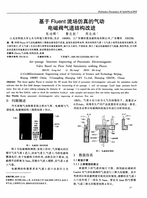
图 1 电 磁 网 三 维 结 构 图
图 2为 电磁 阀原 理 图 , 系统 工作 时 , 泵输 出 的压 气 缩 空气 从 气道 1 入 , 由气 道 2 气 3 当给 电磁 线 进 经 、 。
0 问题 描 述
汽 车座 椅气 动按 摩 系统 主要 由气泵 、电磁 阀 与气 袋组成 , 电磁阀结 构三维 图如 图 l 示 。 所 一 ‘
1ka 0P,气道4 处为大气压的情况下,流量应≥ 出口
65 / i。而 现 有生 产 的产 品 流量 没有 达 到 这一 要求 , . mn L 因此有 必要 对 电磁 阀的流场 分 布进行 分析 和改 进 。
Ai—p sa e S r c u e mp o i g o ne m ai e to a nei r a sg tu t r I r v n f P u t El cr m g t c c
V av s d n lw F e d i u ai w ih n l n l e Bae o F o il Sm lt on t i K F ue t
Z HANG Go g h i n - u L Z i^ I h一 帆 Z HOU Z i h n a h - o g
(.ii n i n e t n ier g sh o o nvri fS in ea d T c nlg e ig 1 v &E vr m n E g ei co l fU iesy o c c n eh o y B in , C l o n n t e o j
基于Fluent的弹道修正弹制导状态气动仿真
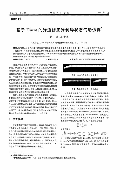
当前 , 弹道修正弹在现代 战争中发挥着越来越 重要的 作用 。弹道修正弹是对传统“ 弹进行 改造 的产物 , 笨” 他依 靠对弹丸的飞行弹道进行一定次数 的修 正 , 可有效 提高弹
Saa — l aa 模 型的求 解 变量 是 , 征 出了 近壁 plrAl rs t m 表 ( 粘性影响 ) 区域 以外 的湍 流运 动 粘性 系数 。 的输运 方
程 为
于控制体 中心 的精度要高 , 特别适合非结构化 网格 。
2 )设 置 流 体 的 物 理 属 性 。材 料 设 为 a , 度 项 设 置 i密 r 为 iel a , “ i oi ” 项 中选 择 stel d d a gs在 Vs s y 一 — c t uhr n 。气 体 黏 a 度 的 S te ad定 律 非 常 适 合 高 速 可压 缩 流 动 。 u rn hl 3 )壁 面 条 件 为 无 滑 移 条 件 , 面 粗 糙 度 选 为 默 认 值 壁 0 5 所 有 其 他 标 量 均 采 用 不 可渗 透 壁 面 条 件 。 .,
比, 即
行修正后可显著提高弹药 的精确打击能力 。
弗 收 稿 日期 :0 0— 4— 9 21 0 0
作者简 介: 秦豪 (9 4 ) 男 , 18一 , 硕士研究生 , 主要从事 简易制导舵机技术研究 。
秦 豪 , : 于 Fu n 的 弹道修 正 弹制导状 态气动仿 真 等 基 le t
第3 l卷
第 7期
四 川 兵 工 学 报
21 0 0年 7月
FLUENT在汽车空气动力学研究中的应用
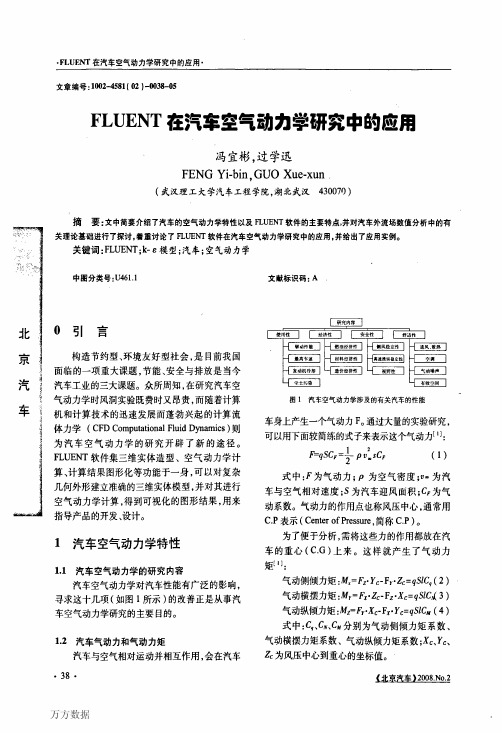
1.2汽车气动力和气动力矩
气动横摆力矩系数、气动纵倾力矩系数;X。、y“
汽车与空气相对运动并相互作用,Fra bibliotek在汽车磊为风压中心到重心的坐标值。
·38·
万方数据
2 FLUENT软件简介
FLUENT软件的最大特点是具有专门几何 模型制作软件Gambit模块,并可以与CAD连接 使用,同时备有很多附加条件和附加方程添加接 口,使用了目前较先进的离散技术和计算精度控 制技术,如多层网格法、快速收敛准则以及光滑 残差法等,数学模型的离散化和软件计算方法处 理较为得当。实际应用中发现,该软件在模拟单 相流动或进出口同向或反向流动时,可以得到较 好的模拟计算结果,且具有一定的计算精度。 FLUENT软件包主要具有常用的6种湍流数学 模型、辐射数学模型、化学物质反应和传递流动 模型、污染物质形成模型、相变模型、离散相模 型、多相模型、流团移动模型、多孔介质、多孑L泵 模型等。
hlel新模型的空气速度分布图研究发现经过改进各个出风口出风量的分配基本满足了设计要求达到了期望的优化目33fluent在汽车超车过程中空气动力特性研究中的应用汽车高速超车时车身周围的空气流场之间将会产生强烈的气动干扰不仅严重影响汽车的气动特性而且危及汽车的操纵稳定性和行驶安全性
·FI。UENT在汽车空气动力学研究中的应用· 文章编号:1002-4581(舵)一∞38一惦
车身上产生一个气动力F。通过大量的实验研究,
可以用下面较简练的式子来表示这个气动力[1]:
1
’
户q.sc,=下1 PtJ=,sC,
(1)
‘
式中:F为气动力;P为空气密度;口一为汽 车与空气相对速度;S为汽车迎风面积;c,为气
动系数。气动力的作用点也称风压中心,通常用
用VC_研发基于FLUENT的高压气淬过程数值模拟软件_英文_

第10卷 第15期 2010年5月167121815(2010)1523772206 科 学 技 术 与 工 程Science Technol ogy and Engineering Vol 110 No 115 M ay 2010Ζ 2010 Sci 1Tech 1Engng 1用VC++研发基于F LUENT 的高压气淬过程数值模拟软件胡祥敏 黄 鹏1,2(广东科学技术职业学院,珠海519090;华南理工大学机械工程学院1,广州510641;肇庆学院机械工程学院2,肇庆526061)摘 要 分析了F LUE NT 的用户自定义函数(UDF )的编译过程,提出了一种在集成开发环境中编写和编译UDF 的方法。
讨论了用面向对象方法(OO )编写UDF 的优势和可能性,提出了通过修改VC 开发环境选项和在程序中增加宏来实现OO 开发。
用OO 法编程,用户可以使用M FC 及其它的库比如Object A RX 来加快开发过程,并降低开发难度。
基于以上方法开发了高压气淬过程的数值模拟软件,F LUE NT 用于计算气体流场和温度场,以及金属温度场,有限元软件FEPG 被F LUE NT 调用,用于计算金属内部的应力和应变。
关键词 数值模拟 F LUE NT 二次开发 高压气淬中图法分类号 TP391.75; 文献标志码 A2010年3月8日收到 F LUENT is one of the most i m portant Finite Vol 2ume Method (F VM )based nu merical si m ulati on s oft 2ware,which has been widely used t o si m ulate the p r ocesses of constant and inconstant fl ow,comp ressible and unco mp ressible fl ow,evaporati on,and combus 2ti on .The s oft w are was written with C language,and a Secondary Devel opment I nterface (S D I )of C language was p resented,which is used t o define material p r oper 2ties and boundary conditi ons,read and edit cell coordi 2nates and variables related t o fields .App licati onscopes are extended and the accuracy of calculati on is i m p r oved because of the UDF .Because F LUENT Cor 2porati on has not p resented an integrated s oft w are devel 2op ing t oolkits f or writing and editing UDFs,users can only write and edit UDFs in s oft w are such as a notepad and then comp ile the p r ogra m s at cons ole or DOS envi 2r onment,which make it very difficult t o edit p r ogra m s and t o find err ors .And t oday,C language has already ev olved t o C++language .One benefit of writing C++p r ogra m s is that object oriented method can be usedrefs .[1,2],which can si m p lify the p r ocesses of p r o 2gra mm ing .Another benefit is that s ome libraries like MFC and Object A RX can be used in p r ogra m s s o that the devel op ing p r ocesses can be much easier .It is ex 2pected t o write and comp ile C++OO F LUENT UDF in M icr os oft VC++I D E and devel op a high p ressure gas quenching syste m in this study .1 Ana lysis of Co m p ili n g Processes of FL U 2ENT UD Fs F LUE NT p r ovides the comp iling envir on ment of UDFs,and its comp iling p r ocesses are as f oll ows:writ 2ing C style UDFs in word -editing s oft w are like note 2pad,and then calling a comp iling command in F LU 2ENT .The command p r oduces a file na med “user _na me .c ”and the file is na med “makefile ”.Every ele 2ment of an array of udf_data in “user_na me .c ”points t o a user functi on .The file na med “makefile ”is a de 2scri p ti on file .Searching paths of header and libraryfiles,static libraries used in comp iling,and thep r ocesses of comp iling are all described in this file .U 2sing the“makefile”as a para meter,F LUENT calls the C comp iler,and then a Dyna m ical L inking L ibrary (DLL)is p r oduced[3].W hen the DLL is l oaded, F LUE NT gets the udf_data array and then gets all user2 defined functi ons for using.Foll owing the above p r ocesses,p r ogra mmers can write and co mp ile F LUENT UDFs in a s oft w are I nte2 grated Devel opment Envir onment(I D E).I n I D E, comp iling op ti ons should be changed manually accord2 ing t o the above descri p ti ons,which is not easy f or most of users.2 Co mpili n g F L UENT U DFs i n VC++I DEW riting and co mp iling p r ogra m s in VC++I D E has many advantages.U sing MFC and other libraries like Object A RX t o write Object O riented C++p r ogra m s ben2 efits writing large p r ogra m s and si m p lifying the p r ogra m2 m ing p r ocesses.Thr ough this way,the user can input data t o the running p r ogra m s thr ough dial og windows. When pr ogra mm ing in VC++I D E,s o me pr oble m s should be considered.First,many C style functi ons pr ovided by F LUE NT Cor porati on should be used in the ne w syste m. They must be recognized by the VC++co mpiler.Second, UDFs and the udf_data array should be ex ported accord2 ing t o C style.T o s olve these p r oble m s,a macr o na med “extern“C”should be added t o the beginning of C++ files.The step s of writing UDFs in VC++I D E can be described as f oll ows.First,running VC++I D E s oft2 ware and selecting appwizard(dll),and then getting a dll p r oject.Second,editing the I D E comp iler op ti ons, and including p r oject“including paths”and“static li2 braries paths”.Third,adding correct F LUE NT static libraries t o the p r oject op ti ons dial og.Fourth,adding functi ons.cpp file t o the p r oject.UDFs will be written in the file.Fifth,writing correct user_na me.cpp file and adding it t o the p r oject.The f or mat of C++files is as foll ows:#include“stdafx.h”extern“C”{#include“udf.h”//user define functi ons……}The above p r ocess can be done manually,and can als o be done by s oft w are[4]s o that p r ogra mmers can concentrate on making UDFs.3 D evelop i n g S i m ul a ti on Software for H i gh Pressure Gas Quenchi n g Syste m by V C++ and F LUENT Compared with quenching p r ocesses by water or oil,high p ressure gas quenching by nitr ogen or heliu m has advantages of unif or m heat transference,reducti on of part defor mati on,and no oxidati on.H igh p ressure gas quenching p r ocesses are widely used in mould in2 dustry.Numerical si m ulati on of fl ow field and te mpera2 ture field in quenched metal by F LUENT,and si m ula2 ti on of stress field and strain field in metal by Finite Ele mentMethod(FE M)are vital t o testify the feasibil2 ity of quenching p r ocesses,t o op ti m ize the p r ocesses, and t o op ti m ize the design of quenching st oves.For si m ulating fl ow field and te mperature field of high p ressure gas quenching,inlet gas vel ocity and temperature,and outlet p ressure can be regarded as boundary conditi ons.I nlet gas vel ocity was p r ovided by the st ove manufacturer,and inlet gas te mperature was measured by the real2ti m e method.The pur poses of UDFs in this syste m are t o realize the foll owing p r oces2 ses:First,changing inlet te mperature and outlet back2 fl ow te mperature.Second,modifying material p r oper2 ties.Third,calculating the metal s olid phase change and the heat p r oduced by the change.Fourth,calcu2 lating the radiati on energy.Fifth,creating dial ogs,377315期胡祥敏,等:用VC++研发基于F LUE NT的高压气淬过程数值模拟软件 which are used t o input data t o Fluent by the real2ti m e method.Sixth,at the end of every ti m e step,extrac2 ting cells te mperature,and then calculating and out2 putting nodes te mperature according t o the require2 ments of FE M s oft w are,s o that the stress and strain of the metal can be calculated by FE M s oft w are.Because F LUE NT and FE M s oft w are use different grid syste m s,and F LUE NT out puts cells te mperature but FE M needs nodes te mperature,it is necessary t o inter polate FE M node te mperature by F LUENT cells te mperature,and it is als o necessary t o judge which F LUE NT cell every FE M node is in,and t o calculate the vect or fr om the cell center t o the node.I f the sum of volume of all the entities f or med by the FE M node and F LUE NT cell surfaces’nodes is equal t o the v ol2 ume of the cell,then the node is in the cell.O ther2 wise,the node is outside the cell.I f the cells in F LU2 ENT have not been refined,the area and nor mal vec2 t ors of all surface can be got by F LUENT macr os,but after grids have been refined,they cannot be got cor2 rectly,excep t for nodes coordinates.So it is the p r o2 gra mmer’s duty t o judge how many points are on a p lane and the area of the p lane.For a tetrahedr on,three nodes are on a p lane.T o judge if a point is in the tetrahedr on,it is necessary t o get the sum of f our tetrahedr on volu me f or med by the point and three points of the tetrahedr ons,and the v ol2 ume of the tetrahedr on.I f they are equal,the point is in the tetrahedr on.O ther wise,the point is outside the tetrahedr on.For a pyra m id,a vertex and a bott om should first be recognized.The characteristic of a bott om is that four points are on a p lane.Random ly select three points of four considered points,and build t w o p lanes, then calculate the nor mal vect ors of the t w o p lanes.I f the t w o vect ors are on the sa me directi on,then the f our points are on a p lane.This p r ocess can be p r ogra mmed by the user,and the user can als o use Object A RX p r o2 vided by Aut odesk Cor porati on,s o that the p r ocess can be si m p lified.For a hexahedr on,a four point bott om and a f our point t op surface should first be recognized.The char2 acteristic of a bott om is that f our points are on a p lane. The other four points are on the sa me side of the p lane. W hen the bott om and the t op surface have been recog2 nized,the user can calculate the nor mal vect ors of the t w o p lanes.I f the directi ons of the t w o p lanes are op2 posite,the user can adjust the sequences of the points on one p lane s o that the nor mals are on the sa me direc2 ti on.Revolve the f our points of the t op surface s o that the points on the above surface and those on the bott om are corres ponding.W hen the hexahedr on has been rec2 ognized,it is easy t o judge if a point is in the Entity according t o the method menti oned bef ore.A si m p le method t o calculate the relati onshi p of F LUE NT cells and FE M nodes is t o judge if a FE M point is in a certain cell one by one.I n fact,this is a ti m e2consu m ing method and the ti m e2comp lexity is O(n),of which the n is the di m ensi on of the cells. One i m p r oved method is t o compare the distances fr om the point t o the cell centers one by one.Then,choo2 sing the first m ini m al distance cells and judge whether the points are in those cells.The comp lexity of this method is O(n),t oo.Because it just costs a little ti m e t o judge whether a point is in the cells,the i m2 p r oved method is a ti m e2saving method.Another i m2 p r oved method uses a m ini2stack data structure.The comp licity of the method is just half of the t w o methods menti oned before.The running of the s oft w are can be described as foll o ws:when the s oft w are starts,it calls initialized functi ons.The first ai m of the functi ons is t o extract F LUE NT cells and corres ponding nodes coordinates. The second ai m is t o l oad FEPG FE M node message4773科 学 技 术 与 工 程10卷files and extract nodes .The third ai m is t o judge which cell each node is in one by one and get the vect or fr om the cell centre t o the FEPG node .W hen a ti m e step is over,the te mperature of the nodes can be inter polated by cells te mperature and te mperature grads and the vect ors,and then a F ORT RAN binary file out puts .Then Calling FEPG FE M Fortran or C p r ogra m s and calculating the stress and strain filed in the metal .Fi 2nally,calculate the p r oble m s of the next ti m e step,un 2til the ti m e is over .The hierarchy structure of user defined classes can be exp ressed as f oll ows fig .1Fig .1 H ierarchy structure of user defined classesSome i m portant classes:Class HEntity{Public:static AcGePoint3d original _point;//AcGePoint3d is definedby Object A RX AcGePoint3dA rray points;//points of the entity bool operat or <(HEntity&en );//comparing the distance fr omentity en t o the original_point and the distance fr om this entity t o the original_point . virtual bool isPointI n It (AcGePoint3d&po )=0;//virtual func 2ti on,t o judge if po is int o the entity . double distanceTo (AcGePoint3d &p );//calculating the distancefor m p t o the center of the entity virtual AcGePoint3d center ();//calculating the center of thecell . int cell_id;//I D of a F LUENT cell }Class HPlaneEntity:public HEntity{Public: virtual double get A rea ();//calculating the area of a p lane entity virtual bool isPointI n It (AcGePoint3d&po )=0;// virtual nor malize ();//arranging the points of the entitypoints sequential }Triangle and quadrangle are inherited fr om HEntity,and the decla 2rati ons of the t w o classes are the sa me as HEntity .Class HBodyEntity:public HEntity{Public: virtual bool isPointI n It (AcGePoint3d&); virtual void nor malize (); virtual double volume ();//calculating the volume of the 3D enti 2ty .}Tetrahedr on,pyra m id and hexahedr on are all in 2herited fr om HBodyEntity,and the declarati ons of the three classes are the sa me as HBodyEntity .4 Exam pleA high p ressure gas quenching st ove (model VG Q150)was studied as an exa mp le .The inner di m en 2si on of the st ove is Ф1200×1320mm 2.The dia meterof the 96sy mmetrical distributed inlet is Ф22mm.The vel ocity of the inlet gas p r ovided by the st ove manufac 2ture is 35m /s .The inlet gas te mperature was measured by a real 2ti m e method .The p ressure in the st ove was four bars .The dra wing of the st ove is sho wn in fig .2.The fl ow field distributi on in the st ove was shown in fig .3.The te mperature field was shown in fig .4.The calcu 2lated and experi m ental te mperature hist ory was shown in fig .5.The te mperature of FEPG nodes is written in a file .After opening it in FEPG,the te mperature filed is sho wn in fig .6.This exa mp le de monstrates that the si m 2ulati on s oft w are can si m ulate the fl ow field and te mpera 2ture field of the quenching gas,the stress and strain of the quenched metal in the st ove .5 Conclusi onNumerical si m ulati on s oft w are based on F LUE NT for high p ressure gas quenching syste m has been devel 2oped by VC++and UDFs .The s oft w are can calculate the fl ow field and te mperature filed of quenching gas,the te mperature field,the s olid phase changing,and577315期胡祥敏,等:用VC++研发基于F LUE NT 的高压气淬过程数值模拟软件the stressandstrain in quenched metal.Fig .2 Gas fl ow syste m in high p ressure gasquenching st ove (1/4view scope)Fig .3 D istributi on field of gas vel ocity inthe axial secti on of stoveFig .4 D istributi on field of metal te mperaturein the axial secti on of stoveFig .5 Experi m ental and calculated te mperatureat the metalcenterFig .6 Temperature distributi on of metal alculated by Finite Ele mentMethod s oft w are FEPGReferences1 Huang Peng .An aut o p r ogra mm ing syste m f or punching machinebased on Object A RX .Q inggong J ixie,2004;(3):72—752 Deng Q in .Realized mechanis m of method in object oriented engineer 2ing database manage ment syste m s .machinery &Electr onics,2001;(4):43—453 F LUENT Cor porati on .F LUE NT UDF manual,20034 Huang Peng,Hu Xiang m ing .Soft w are of secondary devel opment ofF LUENT by VC++.htt p://219.232.54.3/cgi -bin /LB5000/t op 2ic .cgi?forum =51&t op ic =78&show =0,2006—2(下转第3783页)6773科 学 技 术 与 工 程10卷The Research of M ultim ed i a QoS Guaran tee M ethod i n LAN Ba sed on Network Ca lculusQ IU Chun 2r ong(Changsha SocialWork College,Changsha 410004,P .R.China )[Abstract] Basic definiti on and conclusi on of net w ork calculus is researched,and studied RS VP p r ot ocol of I nt 2Serv model .It analyzes the multi m edia strea m QoS guarantee method in typ ic LAN based on the basic deducti on of Net w ork Calculus and p r oposes a net w ork res ource reservati on algorithm ,analyzing the syste m perf or mance .The re 2search result has s ome app licati on value in ad m issi on contr ol technol ogy and QoS manage ment of LAN multi m edia strea m.[Key words] net w ork calculus multi m edia strea m net w ork res ource reservati on(上接第3776页)D evelopm en t of Fluen t Ba sed S im ul a ti on Software for H i gh Pressure Ga s Quench i n g System Usi n g VC++LanguageHU Xiang 2m in 1,HUANG Peng1,2(Depart m ent of Mechanical Engineering,Guangdong I nstitute Of Science And Technol ogy,Zhuhai 519090,P .R.China;Depart m ent of Mechanical Engineering,South China University of Technol ogy 1,Guangzhou 510641,P .R.China;Depart m ent Of Mechanical Engineering,Zhaoqing University 2,Zhaoging 526061,P .R.China )[Abstract] Comp iling p r ocesses of F LUE NT U ser Defined Functi ons (UDF )were analyzed in this paper,and a method t o write and comp ile UDF in s oft w are I ntegrated Devel opment Envir on ment (I D E )was p resented .The ben 2efit and p r obability of devel op ing C++Object 2O riented (OO )UDF were discussed,and thr ough changing VC++I D E p r oject op ti ons and adding extern “C ”macr os in p r ogra m s,a method t o devel op VC++OO UDF p r ogra m s in M icr os oft I D E was p resented .U ser defined classes .M icr os oft Foundati on Class (MFC )libraries and other C and C++libraries like Object Aut oCAD Run 2ti m e Classes (Objext A RX )can be used by this way .U sing this method,si m ulati on s oft w are of high p ressure gas quenching syste m was devel oped .I n this s oft w are,F LUE NT is used t o cal 2culate the fl ow field of gas and the te mperature field of gas and metal,and a Finite Ele mentMethod (FE M )s oft 2ware FEPG called by F LUET N is used t o calculate the stress and strain of quenched metal .[Key words] si m ulati on F LUE NT secondary devel opment gas quenching387315期邱春荣:基于网络演算的局域网多媒体QoS 保障方法研究 。
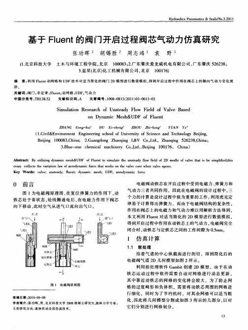
基于Fluent的阀门开启过程阀芯气动力仿真研究
t e di e i ,t ) m m
{ it < O0 ) fi = .1 *阀芯运 动时间 { (me / /
一 ,●●●●●●● ● ● ●. ●.● ● ● ● ●●●● ● ●● ●
e_ e 1= 0 5 *阀芯运动 速度 , gv l ]一 . ; [ 0/
缝 隙区
座 之间保 留了一层 非常小 尺度 的网格[ 2 1 。
2 计 算 结果
21 动铁芯 匀速 运动规律 时计 算结果 . 设 动铁 芯 为匀 速运 动 .设 置 动铁 芯 的运 动速度 分 别 为 01 /、. m s00 5 /、.1 /、. 5 /,图 5 .m s00 /、. m s00 m s0O m s 5 2 0 为人 E压力 为 1 k a时 ,动铁 芯在 不 同运 动速 度情 况 l 0P
13 求 解 设 置 .
图 4为上 阀腔 区与 左 右缝 隙 区 的局 部放 大 图 。 图 中局 部放 大 3和 4为缝隙 。需要 说 明的是 , 当动铁 芯开
度 为 0时 , 芯和 阀座 间 的接 触 面 ( 4中局部 放 大 l 阀 图
对 所 有 区 域 进 行 初 始 化 , 代 时 间 步 长 设 为 迭 00 0 s时 间步数为 3 , . 5, 0 0 最大迭 代数 为 2 0 , 0 0 设置 每个
因此 使用 三角形 网格[ 3 1 。 设 置边 界条 件类 型 :人 口和 出 口均 使 用压力 边 界 条 件 ,同时 将 动 铁 芯 对 应 的所 有 边 进 行 统 一 命 名 为 Vl 。 av 以便于在 下文 中进行 动 网格 区域设 置 。完成 以上 e 所 有工作 以后 。 出 网格 文件 。 输
利用 Fun 2 let D单精度 求解器进行计 算 , 读人并 检 查 网格 , 置长度单位制 。选 择非稳态求解 模型 ,一 设 k 湍
基于Fluent的末制导炮弹初始段气动仿真[1]
![基于Fluent的末制导炮弹初始段气动仿真[1]](https://img.taocdn.com/s3/m/13505b45b307e87101f69677.png)
系数、 俯仰力矩系数变化曲线与实验所得基本一致。 通过以上图表的对比,可以看出仿真所得结果 偏大,分析后可知主要原因有以下方面: 1) 网格划分误差。划分网格过程中,网格模型 的弹体表面由网格面拼接而成, 造成拼接面不光滑, 从而引起附加的阻力、升力等,导致计算结果偏大。
庞英良,等:基于 Fluent 的末制导炮弹初始段气动仿真 这种误差可认为属于计算的系统误差,根据实验数 据进行修正后可以予以消除。
α=0 0.6 0.5
CY
马赫数 试验俯仰力矩系数 M zg 仿真俯仰力矩系数 M zg 相对误差 /% 0.50 0.0250 0.0259 3.60 0.70 0.0232 0.0241 3.88 0.90 0.0184 0.0192 4.35 1.00 0.0216 0.0209 3.24 1.10 0.0251 0.0260 3.59 1.20 0.0220 0.0211 4.09 1.53 0.0252 0.0261 3.57 1.79 0.0293 0.0303 3.41
试验俯仰力矩系数曲线 仿真俯仰力矩系数曲线
0.028
CY
0.35 0.3 0.25 0.2 0.4 0.6 0.8 1 1.2 1.4 1.6 1.8 2 M 2.2
0.04
MZg
0.6 0.8 1 1.2 M 1.4 1.6 1.8 2
0.026 0.024 0.022 0.02 0.018 0.4 0.6 0.8 1 1.2 1.4 M 1.6 1.8 2
表2 全弹模型实验升力与仿真升力系数对比(攻角 α=1°)
试验升力系数 C y 仿真升力系数 C y 相对误差( %) 0.0342 0.0351 2.63 0.0356 0.0370 3.93 0.0423 0.0431 1.89 0.0379 0.0388 2.58 0.0383 0.0392 2.35 0.0368 0.0356 3.26 0.0371 0.0379 2.16 0.0386 0.0394 2.07 马赫数 0.50 0.70 0.90 1.00 1.10 1.20 1.53 1.79
基于Fluent的气力输送弯管流场仿真模拟

2020年增刊前言水泥工程系统粉体物料的主要输送方式是气力输送,包括气力输送泵,气力提升泵,仓式泵,料封泵,空气输送斜槽等设备。
气力输送系统由气力输送设备和管道组成,在输送过程中,由于粉体和输送管道的相互作用,导致输送过程效率下降,同时粉体颗粒对管道造成冲蚀磨损。
计算流体力学(CFD )是计算机辅助工程(CAE )的主要分支,广泛应用于科学研究、工程设计中。
Fluent 是目前国际上通用的商用CFD 软件包,用于模拟复杂条件下的流动、热传递和化学反应。
本文基于Fluent 软件对气力输送管路的弯管两相流场进行了定性仿真模拟,简要介绍Fluent 程序求解步骤,为输送管路的优化设计和复杂流体分析提供理论依据。
1模型建立本文选用某工程输送管道一段80°弯管建立简化模型:弯管内径d =150mm ,弯管半径R =300mm ,进口直段长度500mm ,弯管出口角度80°,出口直段长度500mm ,模型剖面示意见图1。
入口出口50050080°150ΦR 300图1弯管模型基于Fluent 软件平台对流场的模拟包括:(1)前处理器:可以通过GAMBIT 模块建立计算模型、进行网格划分,也可以通过导入其它主流建模软件模型或中间格式,使用Fluent Meshing 模块划分网格;(2)求解器:基于Fluent 进行参数设置和求解计算。
求解器是流体计算软件的核心.可对基于非结构化网格进行求解;(3)后处理器:通过对计算结果的后处理,实现图形图表化的输出显示。
本次使用SolidWorks 软件3D 建模,导入FluentFlow Meshing 模块进行划分网格,网格划分质量会直接影响到计算结果。
为了平衡计算工作量和计算的准确性,此次计算共划分弯管六面体网格数量75540个。
经检查网格质量良好,见图2。
图2弯管网格模型2求解计算粉体颗粒随高速气流在管道里流动,气体是连续相,粉体是离散相,这是典型的气固两相流模型。
利用计算机仿真技术研究气动力提升系统

利用计算机仿真技术研究气动力提升系统引言:气动力提升系统是一种利用空气动力学原理,通过风力将物体或人体提升至空中的系统。
随着科技的不断发展,计算机仿真技术的应用也日益广泛。
本文将探讨如何利用计算机仿真技术研究气动力提升系统,从而提高安全性和系统性能。
一、气动力提升系统的原理气动力提升系统是基于贝努利原理和流体动力学的原理设计的。
根据贝努利原理,当流体速度增加时,压力就会降低。
而气动力提升系统通过设计特定的形状和结构,利用风的速度差异和气流的压力差来实现物体或人体的提升。
二、计算机仿真技术在气动力提升系统中的应用1. 数值计算模型的建立利用计算机仿真技术,可以通过建立数值计算模型来模拟气动力提升系统的工作过程。
首先,需要收集相关气动力学参数,包括空气密度、气流速度、物体形状等。
然后,利用数值计算方法,根据流体动力学定律,建立数学模型。
2. 流场模拟与可视化通过计算机仿真技术,可以对气流的流动进行模拟,并将结果可视化。
利用流场模拟软件,可以模拟出气流在系统内的流动情况,包括速度分布、压力分布等。
同时,通过可视化技术,可以直观地展示出气动力提升系统内部的气流状态,有助于了解系统的运行情况。
3. 动力学仿真与优化除了模拟气流的流动,计算机仿真技术还可进行动力学仿真和优化。
通过建立物体或人体的动力学模型,可以模拟其在气动力提升系统中的运动轨迹和受力情况。
通过对仿真结果进行分析,可以优化系统的设计,提高提升效果和安全性。
三、气动力提升系统仿真技术的优势1. 安全性:通过计算机仿真技术,可以在系统设计阶段模拟出各种情况下的受力和运动情况,从而避免设计缺陷对实际使用的不良影响。
这有助于提高系统的安全性。
2. 成本:利用计算机仿真技术,可以在系统设计和优化阶段快速提供准确的数据和结果,降低试错成本和设备开发周期,对提升系统的研究和开发具有较高的经济效益。
3. 精度:由于计算机仿真技术能够快速计算多参数的复杂运算,因此可以提供较为准确的结果。
- 1、下载文档前请自行甄别文档内容的完整性,平台不提供额外的编辑、内容补充、找答案等附加服务。
- 2、"仅部分预览"的文档,不可在线预览部分如存在完整性等问题,可反馈申请退款(可完整预览的文档不适用该条件!)。
- 3、如文档侵犯您的权益,请联系客服反馈,我们会尽快为您处理(人工客服工作时间:9:00-18:30)。
基于Fluent高压气动驱动系统的仿真研究
董岱;李小宁
【摘要】为获得某高压气动负载驱动系统的驱动特性,建立其包含储气瓶、控制阀和气缸进气腔的三维模型,基于流场仿真软件Fluent平台,运用动网格技术和UDF
实现了该驱动系统的动态仿真,得到三维流场压力、速度等随时间变化和气缸活塞
的运动特性.通过改变系统参数,分析了驱动系统的负载驱动特性随储气瓶初始压力、控制阀通径和气缸缸径的变化规律,为驱动系统的设计提供了参考依据.
【期刊名称】《液压与气动》
【年(卷),期】2015(000)006
【总页数】4页(P76-79)
【关键词】Fluent;仿真;动网格;UDF;高压驱动系统
【作者】董岱;李小宁
【作者单位】南京理工大学机械工程学院,江苏南京210094;南京理工大学机械工
程学院,江苏南京210094
【正文语种】中文
【中图分类】TH138
引言
某高压气动驱动系统主要由储气瓶、控制阀、驱动气缸和负载组成,通过一定压力的压缩空气驱动气缸最终实现负载的高速驱动。
需对该驱动系统进行仿真研究,以
获得系统负载驱动特性,为驱动系统的设计提供参考。
目前,对以上气动驱动系统仿真多采用集中参数方法,但该方法忽略了系统内部结构对气体流动的影响,往往误差较大;随着计算机技术的发展,CFD(Computational Fluid Dynamics,计算流体动力学)技术已经逐步成为流场仿真分析的重要手段[1],运用CFD软件对气动元件流场仿真已有较多研究[2-6]。
本研究以Fluent软件为平台,建立了包括储气罐、控制阀和气缸进气腔等在内的驱动系统三维模型,运用动网格技术对驱动系统进行数值仿真,得到系统的负载驱动特性。
1 驱动系统原理
驱动系统的组成如图1所示。
驱动系统主要包括储气罐、控制阀、驱动气缸、连接管路和负载。
其工作原理为:储气瓶内存储一定压力的压缩空气气体,通过控制阀来控制气瓶向气缸进气腔充气,通过气缸驱动负载,最终实现负载的高速运动;气缸的排气口被关闭,用于气缸运动末端的缓冲。
图1 驱动系统组成
2 仿真模型的建立
2.1 仿真模型
由于Fluent只能对连续流场模型进行分析,故将驱动系统的储气瓶、控制阀、驱动气缸的进气腔以及连接管路建立流场模型。
如图2所示。
图2 系统仿真模型
活塞运动模型如图3所示,由受力方程表示为:
(1)
(2)
其中, m ——活塞质量,kg
x ——活塞位移,m
v ——活塞运动速度,m/s
p1,p2 ——分别为进气腔和排气腔压力,Pa
A1,A2 ——分别为进气腔和排气腔有效面积,m2
C ——滑动摩擦系数,N·s/m
Ff ——库伦摩擦力,N
图3 气缸活塞运动模型
忽略气缸的泄漏,由排气腔的绝热能量方程可得其压力变化方程为:
(3)
V2=A2(L-x)
(4)
其中, V2 ——压气腔体积,m3
L ——气缸行程,m
κ ——等熵指数
p20 ——排气腔初始压力,取大气压为101325 Pa
2.2 动网格设置及UDF
储气瓶、控制阀及气缸进气腔的仿真,由于需要考虑阀芯及气缸活塞运动对流场的影响,需要应用动网格技术。
Fluent提供了三种网格更新模型,即弹簧近似光滑模型(spring-based smoothing)、动态分层模型(dynamic layering)和局部重划模型(local remeshing)。
根据本模型的特点选取动态层模型作为本仿真网格更新方法。
控制阀及活塞的运动由其运动方程定义,即需要编制UDF函数。
根据活塞运动方程,编制活塞运动方程和排气腔压力变化计算程序,进气腔压力则调用Fluent内部函数由流场内部读取[7,8]。
主阀芯的运动则由拟合的主阀芯运动方程
来定义。
2.3 网格划分及Fluent设置
储气瓶、控制阀及气缸进气腔的流场模型如图4所示,利用Fluent前处理软件Gambit建模并划分网格,考虑对称性,采用1/2模型。
储气瓶、气缸及连接管路部分采用六面体网格,控制阀部分结构较复杂,采用适应性更强的四面体网格。
模型的参数如表1所示。
最终划分网格总数为154681。
将控制阀芯端面和气缸活塞端面(如图5)单独设置为壁面条件,应用UDF定义其运动。
湍流模型选取应用较广的标准κ-ε模型。
图4 网格划分
表1 仿真模型参数取值编号参数名称数值1气瓶容积/L11.32气管内径/mm103阀的公称直径/mm84气缸直径/mm405气缸长度/mm10007发射体质量/kg118气瓶初始压力/MPa39气缸活塞摩擦系数/N·s·m-1100
图5 阀芯及活塞端面示意图
仿真计算为非定常,设置储气瓶的初始状态为仿真计算的初始条件,利用Fluent 中的Patch功能对储气瓶区域设置初始压力,温度等参数,其它区域则按常态处理。
3 仿真结果及分析
3.1 仿真结果
按表1参数建立仿真模型,仿真计算120 ms可得不同时刻流场压力云图和速度云图如图6和图7所示。
可以看出,随着时间的变化,活塞的运动使得进气腔的体积不断增大。
运用Fluent动网格技术可以模拟气缸进气腔流场形状随活塞运动的变化情况。
图6 不同时刻流场压力云图
图7 仿真区域内速度云图
气缸活塞速度曲线和进/排气腔的压力变化曲线如图8所示。
在3 MPa初始压力下,活塞运动0.6 m速度可达9.35 m/s。
排气腔的压力增长较为缓慢,对活塞运动的阻碍作用较小。
图8 活塞速度及进/排气腔压力变化曲线
3.2 影响因素分析
1) 气瓶初始压力的影响
图9为在表1参数基础上,改变储气瓶初始压力分别为1.6 MPa和5 MPa时,气缸活塞运动特性。
驱动系统的负载加速性能受初始压力的影响较大,随着初始压力的升高,负载驱动能力不断增强,5 MPa时0.6 m的加速行程,负载速度可达12.96 m/s。
图9 不同初始压力下活塞速度位移曲线
2) 控制阀通径的影响
控制阀通径的大小影响控制阀的流通能力,即影响进气腔的充气流量。
图10为5 MPa压力下控制阀通径分别为6 mm、8 mm和10 mm情况下,气缸活塞速度曲线。
可以看出6 mm和8 mm通径情况下,活塞后程加速能力较弱,特别是在6 mm通径时后程出现减速现象。
主要原因为阀的通径太小,流量较小,进气腔的体积增大使得进气腔压力下降,造成驱动力不足。
图10 不同控制阀通径下活塞速度位移曲线
3) 气缸直径的影响
在3 MPa初始压力下,分别改变驱动气缸的缸径为63 mm和80 mm,得到活塞速度位移曲线如图11所示。
缸径由40 mm增大为63 mm时,驱动能力明显增加;而缸径继续增大至80 mm时,驱动能力反而略有下降,分析主要原因为,缸
径的增大,带来驱动力的增大,然而大的缸径带来大的空气流量需求,在阀的通径不变的情况下,缸径增大同时,进气腔的压力也随之下降,因而并不能有效增大驱动力。
故驱动系统的阀通径及缸径要合理选择,相互配合,才能达到增大驱动能力的目的。
图11 不同缸径下活塞速度位移曲线
4 结论
本研究建立了由储气瓶、控制阀和驱动气缸组成的驱动系统的三维模型,运用Fluent仿真软件,结合动网格技术及UDF实现高压气动驱动系统的动态仿真。
通过改变储气瓶初始压力、控制阀通径及气缸直径等参数,得到不同参数条件下驱动系统的负载驱动特性,分析了各参数对驱动系统驱动能力的影响。
仿真结果表明:为获得较高负载驱动能力,需增大储气瓶压力以及合理配置控制阀通径和驱动气缸缸径。
仿真结果为驱动系统的设计提供了参考依据。
参考文献:
[1] 石俊峰,赵惠清.初始进气阶段气缸的运动特性分析[J].北京化工大学学
报,2008,35(2):73-75.
[2] 朱冬,杨庆俊,包钢.基于FLUENT的气缸充放气二维非定常流场研究[J].液压与气动,2010,(9):17-19.
[3] 葛如海,王桃英,许栋,等.基于动网格和UDF技术的气缸动态特性研究[J].机床与液压,2010,38(21):12-15.
[4] 杨毅峰,樊建春,张来斌.基于FLUENT的气罐泄漏仿真在油气安全中的应用[J].江汉大学学报(自然科学版),2006,34(4):65-68.
[5] 赵斌,孙铁.活塞压缩机气缸内气体的数值模拟[J].压缩机技术,2007,(4):10-12.
[6] 张孝芳,王树宗.潜艇武器发射系统发射控制阀三维流场数值仿真[J].舰船科学技术,2010,(5):125-127.
[7] 韩占忠,等.FLUENT流体工程仿真计算实例与应用[M].北京:北京理工大学出版社,2004.
[8] 江帆,黄鹏.Fluent高级应用与实例分析[M].北京:清华大学出版社,2008.。