512D-W2400L英文无线控台
Leviton Decora Smart Wi-Fi 4-Button Controller说明书

Leviton Manufacturing Co., Inc. Global Headquarters201 N. Service Rd., Melville, NY 11747-3138 Tech Line: 1-800-824-3005 Fax: 1-800-832-9538Visit our Website at: /decorasmartwifi©2021 Leviton Manufacturing Co., Inc. All rights reserved. Subject to change without notice.Decora Smart ® 4-Button Controller with Wi-Fi ® Technologydecora smartDec o raSm ar t® 4-B utt o nCo n t r o l l e r w i t h W i -F i ® T e c h n o l o g yAPPLICATIONThe Decora Smart Wi-Fi 4-Button Controller (DW4BC) provides sophisticated in-wall control of multiple Decora Smart Wi-Fi devices, room lighting scenes and whole house lighting activities. Use with Decora Smart Wi-Fi lighting controls and the My Leviton app to off er an “always there,always on” control center for smart lighting. Adjust devices, activate scenes in a room, or push one button to turn on or off every Decora Smart Wi-Fi light in the home. The DW4BC requires hot, neutral, and ground wires, and does not directlyconnect to a load. The four buttons can be customized for control via the My Leviton app.WORKS WITH MY LEVITONSimply use the My Leviton app to enroll all of your Leviton smart devices, then use the app to assign specifi c functions to each ofthe 4 buttons on the face of the device. For instance, the top button could be “All On”, the 4th button could be “All Off ” and then 3 and 4 could be commonly used scenes such as “Dinner Time” and “Party Mode”. The custom lighting scenes can include any product from the Decora Smart Wi-Fi family including dimmers, switches and smart plugs.CUSTOM ENGRAVED BUTTONS Take it to the next level by ordering custom engraved buttons for your4-Button Controller. These can be designed and ordered at any time through the My Leviton app. The buttons are available in six color options. Custom Engraved Buttons are currently available to U.S. customers only.SAT-10084REV JUL 2021Leviton Manufacturing Co., Inc. Global Headquarters201 N. Service Rd., Melville, NY 11747-3138 Tech Line: 1-800-824-3005 Fax: 1-800-832-9538Visit our Website at: /decorasmartwifi©2021 Leviton Manufacturing Co., Inc. All rights reserved. Subject to change without notice.4 PRODUCT DATAORDERING INFORMATIONFEATURES• To be installed in locations with hot, neutral and ground wires present. An electrical load cannot be directly wired to this product• Use the My Leviton app to create scenes and lighting activities• Buttons feature feedback lights that illuminate upon button press, then vanish • Up to 8 DW4BC’s may be used per Residence• Engraved buttons available in all 6 color options can be designed and ordered at any time through the My Leviton app (U.S. only)BENEFITS• Control room or house scenes from a button• In retrofit applications, may be installed in a multi-way circuit along with a Decora Smart Wi-Fi switch or dimmer• Enact All Off, Movie Time, and more RATINGS• No load control• 120VAC, 50/60HzRATINGS AND CERTIFICATIONS• cULus Listed, Energy Mgmt Equip. 9D34• NOM (Mexico)• Wi-Fi CERTIFIED™• Complies with FCC Part 15, Class B • Contains FCC ID: VPY-LB1GC • Contains IC:772C-LB1GC WARRANTY INFORMATION Five-Year Limited WarrantyWIRING DIAGRAM。
LB Management智能灯泡控制系统用户手册说明书
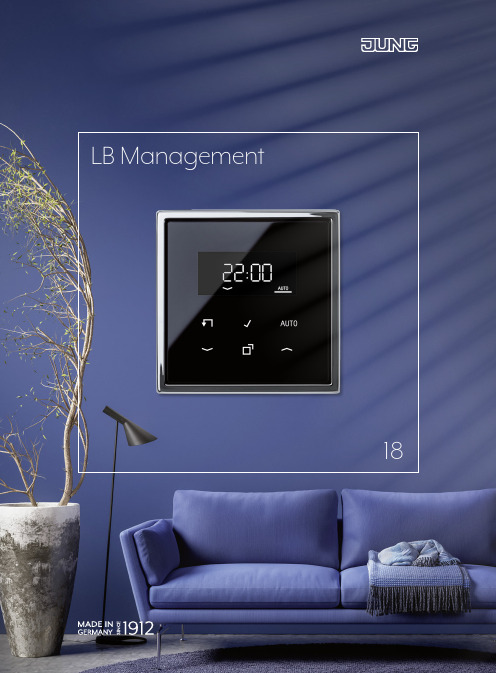
LB Management18CONTENTS The new LB Management 02Overview of the advantages 04In use: Single family house 06In use: Office building 08The controls 10The inserts 11Operation in switch design 12With the press of a button 14The Standard timer 16The Universal timer Bluetooth 20The Clever Config app 22Simply illuminating 24The automatic switches 26The motion and presence detector 28Dimming expertise 30LB Management workbook 3216 Timer with added convenience 26 Control light automatically 04An overview of all advantages22The Clever Config app 1The new LB ManagementThe installation is designed for tradespeople. For example, the small installation depth of only 24 mm (DALI insert 29 mm) creates more space for the wiring. A stable supporting plate in steel, the enclosed mounting claws and increased claw pull-out forces provide a firm hold and optimum alignment in the flush-wall box. In addition, satellites can be connected. Test operation at the site is also possible without a cover. The integrated test button, with which different operating modes can be set, shortens the installation time. The covers are simply pushed on with the help of stable retaining springs in stainless steel. During the installation, the integrated signalling by means of LED or display ensures that no unintended confusion occurs when allocating insert and cover.Out of the JUNG light and blinds management has come theLB Management. With the combination of different inserts andcovers, the modular system provides a solution for virtuallyevery desired function for light and shading control. Whenretrofitting installations, individual components (always insertplus cover) can also be exchanged for new ones from the LB Management and the others can continue to be used.Characteristics are the simple installation and commissioning, the possibility for retrofitting of existing installations andconvenient operation.Overview of the advantagesThe modular principle of the LB Management offers clearadvantages not only for tradespeople but also for ownersand modernisers.1 “Hands-free lighting” with automatic switches: practical and energy-saving 2Alarm function: blinking light for motion detection 3 Automatic light in the guest bathroom: no searching for the light switch 4 Lighting control with satellite unit: extension by operating element 5 Lock-out prevention: deactivation of the automatic shutter control at the press of a button 6 Shading complete areas: shutter control in groups by room, floor or house 7 Astro function: shade a living room with a timer and based on sun positionThe description of these scenarios, withcircuit diagrams and parts list can be foundIn use: Single familyIn private building, the LB Management provides more convenience and energy efficiency with control of light and shadingaccording to need. Daily routines are made easier with automaticfunctions. Individual settings and variable operating possibilities improve living quality.75443126666 76In use: Office buildingIn commercial construction such as office buildings, with the LB Management, the working conditions are optimised in a simple manner. Automatic functions provide more security and convenience here. With constant light regulation, the energy efficiency is increased in addition.1Daylight-linked lightingcontrol in the entrance area:safe and economical2Automatic stairwell light:automatic switches provide safety,also for retrofitting3In the meeting room: always theright light with light and shadingcontrol matched to your needs4Constant light function in the office:optimum illumination with a combinationof presence detectors and DALI push-button controls5Semi-automatic lighting with energy-saving function through appropriate delay times:ideal for small kitchens or server roomsThe description of these scenarios, withcircuit diagrams and parts list can be found532544431 2198STANDARD TIMER WITH DISPLAYThe Standard timer is a 1-channel timer for all inserts. The high-quality,real glass surface has an illuminated display and six sensor buttonsfor operation. The current time can be saved as the switching timeusing fast programming. The locking function deactivates automaticfunctions, satellites and timer programmes. Thanks to the astrofunction , switching times are adapted to the position of the sun.UNIVERSAL CENTRE PLATEThe Universal centre plate with memory and locking function is suit-able for almost all LB Management inserts. A coloured LED is assignedto each rocker half and is used for the function and status display.Opera t ion is performed manually or automatically. The cover forthe automatic shading control is available with appropriate arrow symbols.UNIVERSAL TIMER BLUETOOTHThe Universal timer Bluetooth is an attachment forall inserts for light and shading control. Operationcan be manual with the two rockers or with a smart-phone using the Clever Config app. Colour LEDs forthe display of functions and appropriate buttonprinting optimise operation.The controlsThe inserts LIGHT INSERTS BLIND INSERTS STANDARD CENTRE PLATEThe Standard centre plate is an attachment for all LB Managementinserts. Operation of light and shade is manual. The button can beactuated at the top, bottom and also full surface. The centre plateis available with or without symbols.11Operation in switch designThe controls in the LB Management are all available in the multifaceted JUNG design. As a result, they convince not only with their intuitive operating philosophy, but also with respect to form, colour and material.Without symbols for lighting control Left button without symbols for lighting control“Standard” and “Universal” centre plates, depending on the combined insert, light or shading is controlled manually with the press of a button. The universal design has additional convenience functions. For example, the upper right button (lock symbol) can activate the locking function for all automatic functions and the memory function. Alongside two switching times, a ventilation position for the shutter can also be stored. Thanks to appropriate symbols, operation is self-explanatory.With the press of a buttonThe Standard timerReal glass front in black or white with six sensor buttons forintuitive operation – these are the striking characteristics ofthe Standard timer with illuminated display. In this way, theautomatic control of light and shading becomes particularlyconvenient.SWITCHING TIMESThe Standard timer has two week blocks: fromMonday – Friday and from Saturday – Sunday.For both, time switching for light (4 times) or shade(2 times) can be programmed.ASTRO FUNCTIONThe astro function controls light and shadedepending on sunrise and sunset.SUMMER/WINTER CLOCK CHANGEThe change from summer to winter time and backis automatic. In the process, switching times arechanged accordingly.LOCK-OUT PREVENTIONProtection against being locked out: if the lockingfunction is activated, this is shown clearly on thedisplay .The display switches off automatically aftertwo minutes or a continuous display of thecurrent time is possible . The current time canbe saved as the switching time using fastprogramming . The next blind movementtime or switching time is shown on the display.The integrated Astro function, automaticsummer/winter clock change and a lockingfunction are also included.The Universal timer Bluetooth impresses above all with its operating concept. The opera t ion and parametrisation are carried out both mechanically with button presses and mobile with a smartphone with the Clever Config app. The combination with the brightness/temperature sensor allows auto m atic shade or light control based on sun position. With Bluetooth Low Energy, connecting and data transmission are parti-cularly convenient and secure.UNIVERSAL TIMER BLUETOOTHBrightness andtemperature sensorCREATING A CONNECTION Connecting the app with the LB Management device uses Bluetooth Low Energy. After a successful scan, the devices found are displayed in a clear list. The respective device configurations can then be transferred to the app.SIMPLE SET-UPThe connected devices can now be assigned to rooms and given a name, which simplifies allocation during opera t ion. In the “Parameters” menu point, the device settings can then be individualised as desired or simply copied from devices already stored.TIMER SETTINGAutomatically running timer pro-grammes: creating timer controls for the LB Management is as simple as the alarm on a smartphone. In this way, the respective device is switched on or off or switched to a different status, e. g. “Illumination dimmed 40 %”.ACCORDING TO SUN POSITION As well as programming by time, the sequences can also be set with the astro function dependent on the sun position. In the course of the year, the times for the blinds/shutters moving out and in, and the switching on and off of the light, adapt to the changing sunrise and sunset times.The Clever Config appMore information on the settings for the Clever Config app can be found in the LB Management workbook.MORE SECURITYDevice configuration and device pair-ing can be locked with a password and thus protected from unwanted access. The pairing mode can also be protected so that the device cannot be operated with the app by other people.OPERATION MADE EASYWith one finger tip, the lighting is switched on or off or the illumination is dimmed to the desired brightness. Blinds and shutters are moved out or in or into the desired position. Eventhe louvre angle can be simply set.2322Simply illuminatingLight according to your mood, light on demand – with the components of the LB Management you get more convenience and energy efficiency for your illumination control . Very easy with automatic switches, presence detectors and dimmers.The automatic switchesThe 180° detection range of the automatic switches is monitored by two PIR sensors that can be used individually or together. In the function as movement detector, they are ideal to use in corridors and passages. The 2.20 mversion can be used very well in offices or recreation rooms. The settings in the universal designs are conveniently made using the Clever Config app.Automatic LightThe automatic switches 1.10 m and 2.20 m for illumination control based on movement.Settings using Clever Config appEach of the three PIR sensors is allocated an individually activated area of 120° detection angle. By grouping up to five devices, the detec t ion area can be extended. In its role as a presence detector, the compact device auto m atically provides, for example, energy- saving lighting of the work area in an office. In corridors and hallways on the other hand, the motion detector demonstrates its strengths. The device has a 360° detection area with a radius of 20 metres – assuming an installation height of three metres. The device has a pres-ence, night light, alarm and hotel function as well as constant light control.You can rely on the detection characteristics of the motion/ presence detector. When installed at heights of up to six metres, the unit registers everything that is moving within a diameter of approx. 20 m. For this, the device has three PIR sensors operating independently of each other. All settings are made conveniently using the Clever Config app.Settings usingClever Config app29ROTARY DIMMER/POWER DALI POTENTIOMETER The Standard and Universal rotary dimmers work according to the leading edge phase control or trailing edge phase control principle. Setting the device to the dimming principle that matches the respective consumer is done automatically or also manually for the universal design. A coloured LED indicates the selected operating mode. The Power DALI potentio m eter insert operates lamps with DALI interface, including colour temperature control (tunable white).UNIVERSAL DIMMER FOR RAIL MOUNTING LED/ POWER AMPLIFIERThe dimmer version for the distribution also works according to the leading edge phase control or trailing edge phase control principle. The dimmer for rail mounting is operated via a 2-wire or 3-wire satellite unit or with a button with make contact. The power amplifier LED is used as a capacity expan s ion for spreading larger loads for the LB Management dimmers.MINI UNIVERSAL DIMMER LEDThe compact dimmer is suitable for installation in standard flush-mounting boxes. The operation of all common lamps is then carried out via a 2-wire satellite unit, rotary satellite unit or a button with make contact. The dimmer mini also uses the leading edge phase control or trailing edge phase control principle.LB Management workbookCONTROL VERSIONSThe various possibilities for controlling light and shade described in detail and clearly presented. Including use cases, concrete advantages and notes on connection versions.WIRING DIAGRAMSFrom simple installation of the individual components to complex installations with multiple satellite units or group switching, the descriptions in the work-book are always provided with concrete wiring diagrams.COMMISSIONINGCommissioning and parametrisation of the individual LB Management devices are also explained and illustrated. In this way, the installer can become familiar with the work in advance or also refer to specific areas on location at the site.The handbook for the electrical installer: With the LB Management workbook, the professional has all the information on the modular system in the hand. From the individual building blocks to functions and application examples to concrete wiring diagrams – all the valuable information in an overview.1710 DEStandard touch dimmer insert LED1711 DEUniversal touch dimmer insert LED1708 IEPulse insert1713 DSTEPower DALI push-buttoncontroller TW1704 ESEElectronic switch insert 1-channel1733 DNERotary satellite insert 3-wireULZ 1755 REGAmplifier LEDUD 1755 REGUniversal dimmer LED1720 NESatellite insert 2-wireLi ght1701 SERelay switch insert 1-channel1723 NESatellite insert 3-wire Light ManagementLight ManagementLB ManagementLB ManagementOverview reference numbers1730 DDStandard rotary dimmer LED 1731 DDUniversal rotary dimmer LEDL it1240 STEPush-button controller1202 URERelay switch insert 2-channel 1224 LEDUDELED universal touch dimmer insert 1225 SDEStandard touch dimmer insert 1208 UI Pulse unit1254 TSETRONIC switch insert 1201-1 URERelay switch insert with floating contact 1252 UDEUniversal 2-gang dimmer insert 1244 NVSELV triac switch insert1220 NESatellite insert “2-wire”1201 URERelay switch insert 1-channel 201 TETimer switch insert1223 NESatellite insert “3-wire”254 NIE1Satellite rotary dimmer insert1730 JEStandard blinds insert 1731 JEUniversal blinds insert B l i n d Blinds ManagementLB Management230 MEMotor control insert 232 MEMotor control insert 32 SDSunlight/dawn sensorULZ 1215 REGUniversal amplifier for rail mountingUD 1255 REGUniversal dimmer for rail mounting225 NVDERotary dimmer insert 225 TDETRONIC rotary dimmer 266 GDERotary dimmer insert 254 UDIE1Universal rotary dimmer insertBlind Blinds ManagementAS rangeBlinds ManagementA rangeCD rangeLB Management LB ManagementA 5232 S..Centre plate with sensor connectionA 5232 T3..Centre plate with timer functionuniversalA 5232 TS3..Centre plate with timer functionuniversalA 5232..Centre plate standardAS 5232 MS..Centre plate with memory functionAS 5232 MS..Centre plate with memory functionAS 5232..Centre plate standardA 5232 BF..Centre plate standardA 5232 BFMS..Centre plate with memory functionA 5232 MS..Centre plate with memory functionA 5232 MS..Centre plate with memory functionBliA 5232 T3..Centre plate with timer functionuniversalA 5232 TS3..Centre plate with timer functionuniversalA 5232 ST..Centre plate with timer functionstandardCD 5232 ST..Centre plate with timer functionstandardCD 5232 TS3..Centre plate with timer functionuniversal and sensor connectionCD 5232..Centre plate standardCD 5232 MS..Centre plate with memory functionCD 5232 MS..Centre plate with memory functionCD 5232 S..Centre plate with sensor connectionCD 5232 T3..Centre plate with timer functionuniversalA 5232 BFMS..Centre plate with memory functionA 5232 BFS..Centre plate with sensor connectionL i g h tLight ManagementLB Management..5201 DTST..Standard timer switch..5201 DTU..Universal timer switch A 1561.07 BF..Standard centre plate..1561.07..Standard centre plate ..1561.07 U..Universal centre plate A 5201 DTST..Standard timer switchCD 5201 DTST..Standard timer switchCD 5201 DTU..Universal timer switch CD 1561.07..Standard centre plate CD 1561.07U..Universal centre plateA 1561.07U..Universal centre plate A 1561.07U BF..Universal centre plate A 5201 DTU..Universal timer switch L i tB l i Blinds Management Light Management LB Management LB ManagementLS rangeAS rangeA rangeA 1561.07..Standard centre plateAS 1561.07..Standard centre plate AS 1561.07U..Universal centre plate.. 5232 ST..Centre plate with timer function standard.. 5232 T3..Centre plate with timer function universal.. 5232 TS3..Centre plate with timer function universal and sensor connection .. 5232..Centre plate standard.. 5232 MS..Centre plate with memory function .. 5232 MS..Centre plate with memory function .. 5232 S..Centre plate with sensor connectionCD rangeLS rangeLight ManagementAu t o m a t i c s w i t c hLight ManagementLight Management LB ManagementLB ManagementLS range.. 1280-1..Universal automatic switch 2.2 mDAW 360..Ceiling automatic switch PMU 360..Universal presence detector.. 1280..Standard automatic switch 2.2 m .. 1180..Standard automatic switch 1.1 m .. 1180-1..Universal automatic switch 1.1 m .. 1180 WU..Standard automatic switch 1.1 m IP44.. 1180-1 WU..Universal automatic switch 1.1 m IP44t t i c s i t c CD rangeAS/A rangeLB Management CD 1280..Standard automatic switch 2.2 m CD 1180-1 WU.. Universal automatic switch 1.1 m IP44A 1180-1 WU..Universal automatic switch 1.1 m IP44A 1280..Standard automatic switch 2.2 mA 1280-1..Universal automatic switch 2.2 mCD 1180..Standard automatic switch 1.1 m CD 1180-1..Universal automatic switch 1.1 m CD 1180 WU..Standard automatic switch 1.1 m IP44A 1180..Standard automatic switch 1.1 m A 1180-1..Universal automatic switch 1.1 m A 1180 WU..Standard automatic switch 1.1 m IP44CD 1280-1..Universal automatic switch 2.2 mALBRECHT JUNG GMBH & CO. KGP.O. Box 132058569 SchalksmuhleGermanyPhone +49 2355 806-553Fax +49 2355 806-254*********************For sales contacts in your country see:/contactBL-BG-P。
192控台说明书

DMXMASTER512使用说明书 说明1、192DMX CHANNEL2、有30个BANKS,每个BANK有8个可编程的SCENES3、有8个可调电位器调节输出大小4、内置MIC头,提供声音触发5、在自动触发状态,通过TAP SYNC键或SPEED电位器确定自动触发时间。
6、有MIDI介面,可随时用MIDI信号控制。
7、4位数码管显示。
8、第一数码管显示CHASES,第二位数码管显示SCENES。
9、第三、四位数码管显示BANKS。
10、第二三四位元数码管显示步数或0-255或TIME。
11、1BLACKOUT功能可用手动或MIDI作遥控控制。
12、CHASES编程和CHASES运行功能,可用手动或用MIDI遥控控制。
13、输出延时功能,用FADE TIME电位器调节延时时间。
14、DMX输出极性选择。
一、功能说明1、SCANNERS:电脑灯开启通道(1—12)。
2、SCENS:功能参数推杆,(PAGE SELECT)A---B 翻页。
调控参数16个。
3、BANK:上下数字键,101----130改变。
4、PROGRAM:编程进入键。
5、MIDI/ADD:编辑储存键。
6、AUTO/DEL:程序运动和程序删除键。
7、CHASE1----CHASE6:场编辑键。
8、BLACK OUT:关闭程序键。
9、FADE TIME--SPEED:程序运行时间和每步运行时停留速度。
操作说明1.介绍1、每个SCENE有192个DMX通道,可对每个通道的输出进行调节(由通道按键和可调电位器对通道输出进行调节)。
2、每个BANK可编程8个SCENS,在SCENE运行时是一个BANKS中的已编程的各个SCNEN连续运行,周而复始。
3、用↑或↓键选择BANK,也可通过MIDI介面,用MIDI信号选择,30个BANKS。
每次只能选一个BANK。
4、SCENES可自动地运行,运行时间由TAP SYNC/DISPLAY键决定。
Armacost Lighting Wi-Fi LED Lighting Controller Mo
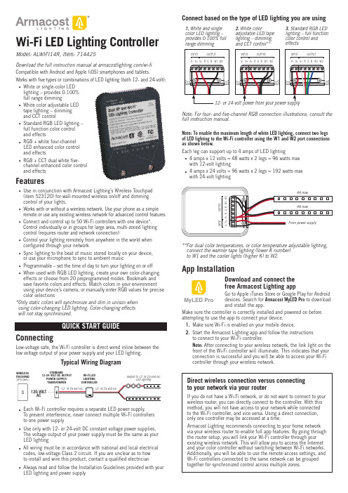
Wi-Fi LED Lighting Controller Model: ALWIFI14R, Item: 714425Download the full instruction manual at /wi-fiCompatible with Android and Apple (iOS) smartphones and tablets. Works with fi ve types or combinations of LED lighting (both 12- and 24-volt): White or single-color LEDlighting – provides 0-100%full range dimmingWhite color adjustable LEDtape lighting – dimmingand CCT controlStandard RGB LED lighting –full function color controland effectsRGB + white four-channelLED enhanced color controland effectsRGB + CCT dual white fi ve-channel enhanced color controland effectsFeaturesUse in conjunction with Armacost Lighting’s Wireless Touchpad(item 523120) for wall-mounted wireless on/off and dimmingcontrol of your lights.Works with or without a wireless network. Use your phone as a simple remote or use any existing wireless network for advanced control features Connect and control up to 50 Wi-Fi controllers with one device*.Control individually or in groups for large area, multi-zoned lightingcontrol (requires router and network connection)Control your lighting remotely from anywhere in the world whenconfi gured through your networkSync lighting to the beat of music stored locally on your device,or use your microphone to sync to ambient musicProgrammable – set the time of day to turn your lighting on or offWhen used with RGB LED lighting, create your own color-changing effects or choose from 20 preprogrammed modes. Bookmark andsave favorite colors and effects. Match colors in your environmentusing your device’s camera, or manually enter RGB values for precise color selections* O nly static colors will synchronize and dim in unison whenusing color-changing LED lighting. Color-changing effectswill not stay synchronized.ConnectingLow-voltage safe, the Wi-Fi controller is direct wired inline between the low voltage output of your power supply and your LED lighting.Typical Wiring DiagramWIRELESSTOUCHPAD(OPTIONAL)ACSTANDARD12-24 VOLT DC OUTPUTPOWER SUPPLY/WI-FI LEDLIGHTINGOutput to 12- or 24-volt DCLED lightingEach Wi-Fi controller requires a separate LED power supply.To prevent interference, never connect multiple Wi-Fi controllersto one power supplyUse only with 12- or 24-volt DC constant voltage power supplies.The voltage output of your power supply must be the same as yourLED lightingAll wiring must be in accordance with national and local electricalcodes, low-voltage Class 2 circuit. If you are unclear as to howto install and wire this product, contact a qualifi ed electricianAlways read and follow the Installation Guidelines provided with yourLED lighting and power supplyfull instruction manual.Note: To enable the maximum length of white LED lighting, connect two legsof LED lighting to the Wi-Fi controller using the W1 and W2 port connectionsas shown below.Each leg can support up to 4 amps of LED lighting4 amps x 12 volts = 48 watts x 2 legs = 96 watts maxwith 12-volt lighting4 amps x 24 volts = 96 watts x 2 legs = 192 watts maxwith 24-volt lighting** F or dual color temperatures, or color temperature adjustable lighting,connect the warmer tape lighting (lower K number)to W1 and the cooler lights (higher K) to W2.App InstallationDownload and connect thefree Armacost Lighting appGo to Apple iTunes Store or Google Play for Androiddevices. Search for Armacost MyLED Pro to downloadand install the app.Make sure the controller is correctly installed and powered on beforeattempting to use the app to connect your device.1. Make sure Wi-Fi is enabled on your mobile device.2. Start the Armacost Lighting app and follow the instructionsto connect to your Wi-Fi controller.Note: After connecting to your wireless network, the link light on thefront of the Wi-Fi controller will illuminate. This indicates that yourconnection is successful and you will be able to access your Wi-Ficontroller through your wireless network.Direct wireless connection versus connectingto your network via your routerIf you do not have a Wi-Fi network, or do not want to connect to yourwireless router, you can directly connect to the controller. With thismethod, you will not have access to your network while connectedto the Wi-Fi controller, and vice versa. Using a direct connection,only one controller may be accessed at a time.Armacost Lighting recommends connecting to your home networkvia your wireless router to enable full app features. By going throughthe router setup, you will link your Wi-Fi controller through yourexisting wireless network. This will allow you to access the Internetand your color controller without switching between Wi-Fi networks.Additionally, you will be able to use the remote access settings, andWi-Fi controllers connected to the same network can be groupedtogether for synchronized control across multiple zones.MyLED ProYou are required to create an Armacost Lighting account upon initial setup. This account registration is used only to protect your devices and to permit remote usage. Next, you will be prompted to select the type of lighting you are connecting. Choose the mode that applies to the type of lighting you are using. For example, if you are using single color or white LED lighting, select “DIM,” and your app will then be confi gured as an LED dimmer.DIM: White/Single Color DimmerCCT: Color Temperature AdjustableRGB: RGB MulticolorRGBW: RGB + Single ColorRGBWW: RGB + Dual ColorNext, you will see a list of all Wi-Fi controllers confi gured on this network. Here, you can access settings and controller properties as well as turn your lighting on/off. Tap the controller name to begin using your lighting, or press and hold to change basic device properties. It is recommendedthat you rename each controller for its location or use.or press and hold to modify controller propertiesTap the powerbutton to toggle the IMPORTANT: If the app displays the error message below, pull downto refresh the controller list.Cannot find any LED controller(s). Please check your device Wi-Fi setting and confirm that the LED controller(s) are plugged inIf the Wi-Fi controller still does not appear, turn your device Wi-Fi connection off and back on and check your network settings.Connect to Smart Speaker/Virtual AssistantBefore beginning use with the following third-party devices, make sure you have setup your Wi-Fi controller through the MyLED Pro app and signed into your Armacost Lighting cloud account. Remote authorization is also required (enabled by default on initial setup).Amazon AlexaIn your Amazon Alexa App, search the skills database for “Magic Home”, then tap enable.Link your Armacost account with the Magic Home Skill. Enter the user name and password that you created in the Armacost MyLED Pro app. Next, discover your Wi-Fi controllers by pressing the Discover Devices button on your app. You can also say, “Alexa, discover devices.” Wi-Fi controllers confi gured on the same wireless network will automatically populate.After your Wi-Fi controller(s) have been discovered, you can rename them in the Alexa app to your preferred names. It is recommended to name them for their location or use, e.g. “Offi ce lights” or “Countertop lights.” Now your lights are ready to control.For a list of additional commands, see the Amazon skill page. Different functions will be available depending on the type of lighting connected to your Wi-Fi controller. Here are some examples:“Alexa, turn on bedroom lights to 20 percent”“Alexa, turn off kitchen counter lights”“Alexa, change accent lights to red”Google HomeIn your Google Home App, navigate to the main menu, then Home control. Press the plus icon to add a device and select “Magic Home Wi-Fi”. All app permissions for Google Home must be granted to complete the setup.Link your Armacost account with the Magic Home Action. Enter the user name and password that you created in the Armacost MyLED Pro app. Google Home will automatically detect compatible devices on the linked home network, and will ask you to assign a room.Press “Done” when you have selected a room and your setup will be complete. You can now assign a nickname to your device. It is recommended to name them for their location or use, e.g. “Offi ce lights” or “Countertop lights.”Now your lights are ready to control. Different functions will be availabledepending on the type of lighting connected to your Wi-Fi controller. Here are some examples:“Hey Google, turn on offi ce lights to 100 percent”“Ok Google, turn bedroom lights to blue”IFTTTIn your IFTTT app or online account, search for the “MagicHue” Service and connect to it.You will then be prompted to link your Armacost Account with the MagicHue Applet. Please enter the user name and password that you created in the Armacost MyLED Pro app.Next, simply enable the applet(s) of your choice. Some applets may require downloading of the IFTTT app to your smartphone. Different functions will be available depending on the type of lighting connected to your Wi-Fi controller.Factory ResetIf you incorrectly entered your network password or have anotherincorrect setting, the link light will not turn on. You will not be able to access the Wi-Fi controller and you will need to do a factory reset. 1. Locate the pinhole on the front of the unit, labeled RESET.2. Using the included straight pin, or a paper clip, insert straight into the pinhole to depress the reset button.3. Continue to press and hold the reset button for ten seconds, then release.The unit will power off and back on and cycle the lighting to indicate the reset has been successful. You can now connect back to your Wi-Fi controller using its default settings. Return to step 1 under “App Installation.”For the full app manual and how-to videos, visit /wifi .mountingTo buy online, or to learn more, visit /dimmers.SPECIFICATIONSInput voltage ................................................................................12-volt or 24-volt DC Output channels .......................................................................................................5Maximum lighting load ....................................................................4 amps per channel Working temperature ..............................................................-5 to 130°F (-20 to 55°C)Wireless working frequency ..............................................................................2.4 GHz FCC ID ..............................................................................................2AIPIALWIFI14R Country of origin .................................................................................................China Limited one-year warranty. This product is for dry location use only. Improper installation,improper powering, abuse, or failure to use this device for its intended purpose will void warranty. Proofofpurchaseisrequiredforallreturns.Questions?*********************************.This device complies with Part 15 of the FCC Rules. Operation is subject to the following two conditions: (1) this device may not cause harmful interference, and (2) this device must accept any interference received, including interference that may cause undesired operation. Changes or modifi cations to this unit not expressly approved by the party responsible for compliance could void the user authority to operate the equipment.Designer-style switch plate and allmounting screws included.© 2018 Armacost Lighting. All rights reserved.180103。
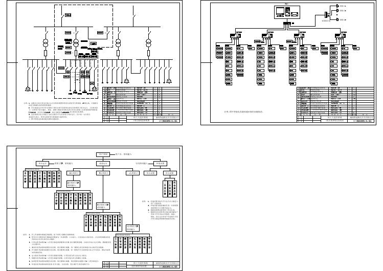
变压器监控系统图-变压器监控系统图
H3C无线控制器
华三--H3C无线控制器与无线终端设备H3C WX5002无线控制器与中端交换机用插板EWP-WX5002-64-H32端口千兆Combo无线控制器(支持64AP)LIS-WX-32无线控制器license费用-管理32APEWP-WX5004-H3H3C WX5004-4端口千兆Combo无线控制器LSKM2150A150W 交流电源模块LSWM1WCM10H3C S5800 系列-无线功能模块-OSM SlotLSWM1WCM20H3C S58 系列-无线功能模块-接口模块扩展插槽LSPM2150D H3C S5500 150W 直流电源模块H3C WX6103无线控制器与插板模块EWP-WX6103-H3H3C WX6103 无线控制器主机LSQM1WCMB0S7500E 无线控制器业务板模块EWPXM1WCMB0WX6103 无线控制器主控板模块EWPXM1G24XA024端口千兆无线控制器接口板(Combo+Slot插槽) EWPXM1FWA0H3C WX6103-EWPXM1FWA0-无线安全业务板模块LSRM1WCM2A1S9500E 无线控制器业务板H3C WX6103无线控制器配置模块LSQM1AC650H3C PSR650A 交流电源模块,650WLSQM1DC650H3C PSR650D 直流电源模块,650WEWPXM1XP2P H3C WX6103-2端口万兆以太网XFP光接口模块EWPXM1XP1P H3C WX6103-1端口万兆以太网XFP光接口模块LIS-WX-128无线控制器license费用-管理128APH3C WA1208E-主机EWP-WA1208E-GP无线局域网单G模块大功率接入点EWP-WA1208E-GP-FIT无线局域网单G模块大功率接入点-FITH3C无线局域网接入点设备EWP-WA2110-AG-FIT H3C WA2110-AG-无线局域网AG双模单频可管理型接入点-FIT H3C WA2200-主机EWP-WA2210-AG H3C WA2210-AG 无线局域网室内型AG单频双模接入点EWP-WA2220-AG H3C WA2220-AG 无线局域网室内型AG双频双模接入点EWP-WA2220E-AG H3C WA2220E-AG 无线局域网增强型AG双频双模接入点H3C WA2220X-AGP 无线局域网室外型AG双频双模2.4GHz大功EWP-WA2220X-AGP率接入点EWP-WA2220E-AG-T H3C WA2220E-AG-T-车载无线接入点(MR)H3C WA2210X-GE-无线局域网室外增强型802.11b/g单频双模EWP-WA2210X-GE接入点EWP-WA2220X-AGE H3C WA2220X-AGE-无线局域网室外增强型AG双频双模接入点H3C WA2210E-GE,无线局域网增强型802.11b/g单频双模接入EWP-WA2210E-GE点EWP-WB2320X-AGE H3C WB2320X-AGE,无线网桥设备EWP-WA2200-WOU H3C WA2200-无线局域网接入点室外单元模块EWP-WA2210-AG-FIT H3C WA2210-AG 无线局域网室内型AG单频双模接入点-FIT EWP-WA2220-AG-FIT H3C WA2220-AG 无线局域网室内型AG双频双模接入点-FIT EWP-WA2210X-GE-FIT H3C WA2210X-GE-无线局域网室外增强型802.11b/g单频双模接入点-FITEWP-WA2220X-AGP-FITH3C WA2220X-AGP 无线局域网室外型AG双频双模2.4GHz大功率接入点-FITEWP-WA2220X-AGE-FITH3C WA2220X-AGE-无线局域网室外增强型AG双频双模接入点-FITEWP-WA2210E-GE-FITH3C WA2210E-GE-无线局域网增强型802.11b/g单频双模接入点-FITEWP-WA2220E-AG-FIT H3C WA2220E-AG 无线局域网增强型AG双频双模接入点-FIT EWP-WB2320X-AGE-FIT H3C WB2320X-AGE-无线网桥设备-FITEWP-WH2530X-DAG-FIT H3C WH2530X-DAG-无线Mesh设备-FITH3C 无线局域网2.4GHz天线组件-全向&定向天线-802.11b/gTQJ-SA800/2500-3全向天线-824~960/1710~2500MHz-3dBi-垂直-360DEG-50W-0r-N(F)-是TQJ-2400-11-T2全向天线-2400-2500MHz-11dBi-垂直极化-150W-2r-N型母头-自带支架TDJ-SA2400-11-90定向天线-2400~2500MHz-11dBi-90deg-Vertical--0r-300W-with support-N(female)-0.28mTQJ-2400BKF-Y定向天线-2.4~2.483GHz-8.5dBi-80度-垂直极化-50W-N-K-否SL13090A全向天线-2.4~2.5GHz-5dBi-垂直极化-全向-10W-N-K-否TQC-2400CI全向天线-2.4~2.483GHz-5.5dBi-垂直极化-50W-SMA-RP-否TDJ-2400IA(-45)定向天线,2.4~2.5GHz,15dBi,72deg,负45度,100W,N-K,是SL14011A定向天线,2.4~2.5GHz,15±1dBi,30±3deg,垂直极化,100W,N-K,否定向天线,2.4~2.5GHz,10±1dBi,55±3deg,垂直极SL14166A化,100W,N-K,否H3C 无线局域网5.8GHz天线组件-全向&定向天线-802.11a定向天线-5725~5850MHz-17dBi-25deg-垂直TDJ-DBS5800-17-50W-0r-N-Female-自带支架全向天线-5725~5850MHz-12dBi-垂直TQJ-5800-12-T0-12dBi-5W-0r-N(female)-自带支架定向天线-5.725~5.85GHz-29dBi-6度-垂直或水平-100W-N-K-TDJ-5800P6否全向天线-5.725~5.875GHz-5dBi-垂直极化-全向-100W-N-K-SL13089A否定向天线-2.4~2.5&5.15~5.85GHz-12&15dBi-45&20度-垂直极TDJ-2458BKC化-50W-N-K-否定向天线-2.4~2.5&5.15~5.85GHz-2.5&4.5dBi-360度-垂直极TQJ-2458XTJ1化-50W-N-K-否TDJ-5158BKT60-2定向天线-5150-5850MHz-17dBi-60°-垂直极化-50W-N型H3C 无线终端设备发货附件一次电源-0degC-40degC-100V-240V-48V/0.5A-AC电源线可拆FSP025-1AD207A卸CAB-PGND-Pwr-3m外部电源线-机箱PGND-12AWG-3m-(OT6-4)CAB-RF-0.2m-SMA射频电缆-0.2m-(SFF50-3)-(N50直公 to SMA50直母)CAB-RF-1.83m-(2*NSM+RG8/U)射频电缆-1.83m-50ohm-N50直公-(COAX-RG8/U)-N50直公CAB-RF-4.5m-(2*NSM+RG8/U)射频电缆-4.5m-50ohm-N50直公-(COAX-RG8/U)-N50直公CAB-RF-10m-(2*NSM+RG8/U)射频电缆-10m-50ohm-N50直公-(COAX-RG8/U)-N50直公射频电缆-1.83m-50ohm-N50直公-(COAX-RG8/U)-反极性SMA直CAB-RF-1.83m-(N+RG8+SMA)母射频电缆-6.1m-50ohm-N50直公-(COAX-RG8/U)-反极性SMA直CAB-RF-6.1m-(N+RG8+SMA)母射频同轴连接器-N-50ohm-直式-母-配接带N型头的电缆-双阴BNC-RF-N-50-KK转接器,外壳镀三元合金射频同轴连接器-N-50ohm-直式-公-配接N型接头的电缆-双阳N-50JJ转接器信号避雷器-2.5KA@8/20us-300V@Line-Earth-10/100MPOE-MHPoE-RJ45&48VDC JACKMHT6000-N-1天馈避雷器-10KA-20V-2.4~6.0GHz-100W-N-F/N-MSLPS-2504无源分路器-2G/3G-1分4功分器-800~2500MHz-N(F)-SLPS-2503无源分路器-一分三-微带线-800~2500MHz-N/female-无源SL21357B无源分路器-WLAN/3G-1分2功分器-1700~2500MHz-N(F)N-50JR负载-0~8GHz-50ohm-<1.25-2W-N MalePSMA-50KR负载-DC~12.4GHz-50ohm-<=1.25-1W-RSMA FemaleSFP-FE-BX15-U-SM1310SFP模块,-40~85℃,1310nm,15km,LCOP-DLC-10m-S光纤连接器-DLC(GM-8T)-SC*2-单模-7mm-10mEWPA-IM壁挂组件-WA2200OANT-2.4/5.8G H3C WA2200 室外天线安装套件OP-A H3C WA2200,室外电源安装套件EWP-WA2200-WOU H3C WA2200-无线局域网接入点室外单元模块CB-2412/2462MHz合路器-WLAN-2412/2462MHz-NFCAB-AC Pwr-5m-PS4M AC电源线-5m-(PI直公)-(227IEC53 RVV1.0^2(3C))-(PS4公) FSP025-1ADF07B一次电源--30℃-55℃-90VAC-264VAC-48V/0.52AH3C无线控制器用SFP模块SFP-GE-LH40-SM1310光模块-SFP-GE-单模模块-(1310nm,40km,LC)SFP-GE-LH40-SM1550光模块-SFP-GE-单模模块-(1550nm,40km,LC)SFP-GE-LH70-SM1550光模块-SFP-GE-单模模块-(1550nm,70km,LC)SFP-GE-SX-MM850-A光模块-SFP-GE-多模模块-(850nm,0.55km,LC)SFP-GE-LX-SM1310-A光模块-SFP-GE-单模模块-(1310nm,10km,LC)SFP-GE-LX-SM1310-BIDI光模块-SFP千兆BIDI光模块-TX1310/RX1490,10km,LCSFP-GE-LX-SM1490-BIDI光模块-SFP千兆BIDI光模块-TX1490/RX1310,10km,LCXFP-LX-SM1310光模块-XFP-10G-单模模块-(1310nm,10km,LC)XFP-SX-MM850光模块-XFP-10G-多模模块-(850nm,300m,LC)27,000.00XFP-LH40-SM1550-F1XFP万兆光模块(1550nm,40km,LC)H3C 有线无线一体化交换机设备H3C WX3024-PoEP-24端口千兆(4 SFP Combo+Slot插槽+PoE EWP-WX3024-POEP-H3Plus)有线无线一体化交换机LIS-WX-12有线无线一体化交换机license费用-管理12APH3C WX3010-PoEP-10端口千兆(8GE-T+2SFP)有线无线一体化交EWP-WX3010-POEP-H3换机1个WX3010有线无线一体化交换机捆绑10个WA2210-AG-FIT EWP-Z2-1无线局域网室内型AG单频双模接入点1个WX3024有线无线一体化交换机捆绑10个WA2210-AG-FIT EWP-Z2-2无线局域网室内型AG单频双模接入点3个WX3024有线无线一体化交换机捆绑10个WA2210-AG-FIT EWP-Z2-3无线局域网室内型AG单频双模接入点H3C WX3008-PoEP-8端口千兆(8GE-T+PoE Plus)有线无线一体EWP-WX3008-POEP-H3化交换机H3C 有线无线一体化交换机选配模块自带一个FLATPACK 1500电源模块和5根电缆的RPS冗余电源AC-RPS1000-A3(AC-RPS1000-A3,H3C面板),2个槽位可插2个电源模块CAB-RPS PoE-2m-JD5RPS电源线-2.0m-(大插头)-(SJTW2芯12AWG黑)-(大插头) LS5M1XP1PB H3C S5100EI 单端口万兆以太网光接口板(XFP)LS5-FL-B安装弯角组件H3C WA2600-主机H3C WA2610E-AGN 802.11n无线局域网增强型2.4/5GHz单频双EWP-WA2610E-AGN-FIT模接入点-FITH3C WA2620E-AGN 802.11n无线局域网增强型2.4&5GHz双频双EWP-WA2620E-AGN-FIT模接入点-FITH3C WA2610E-AGN 802.11n无线局域网增强型2.4/5GHz单频双EWP-WA2610E-AGN模接入点H3C WA2620E-AGN 802.11n无线局域网增强型2.4&5GHz双频双EWP-WA2620E-AGN模接入点H3C WA2620-AGN 802.11n无线局域网室内型2.4/5GH双频接入EWP-WA2620-AGN点H3C WA2620-AGN 802.11n无线局域网室内型2.4/5GH双频接入EWP-WA2620-AGN-FIT点-FITH3C WA2612-AGN 802.11n无线局域网室内型2.4/5GHz单频接EWP-WA2612-AGN-FIT入点-FITH3C WA2612-AGN 802.11n无线局域网室内型2.4/5GHz单频接EWP-WA2612-AGN入点EWP-WA2610-AGN-FITH3C WA2610-AGN 802.11n无线局域网室内型2.4/5GHz单频接入点-FITEWP-WA2610-AGNH3C WA2610-AGN 802.11n无线局域网室内型2.4/5GHz单频接入点H3C WA2600-天线TQJ-2458MIC×6全向天线-2.4G~2.5GHz,5.15G~5.85GHz-2.5dBi@2.4G,4.5dBi@5G-全向-50W-RPSMA-吸顶安装内置6天线TQJ-2458MIK×3全向天线-2.4G~2.483GHz,5.15G~5.85GHz-2.5dBi@2.4G,4dBi@5G-全向-50W-RPSMA-吸顶安装内置3天线H3C WA2600-发货附件POE-3信号避雷器-3KA@8/20us-350V@Line-Ground-33.6W-1000MPoE-RJ45&48VDC JACKH3C 11n无线网卡EWP-WN612H3C WN612-11n 双频USB无线网卡无线控制器选配电源线CAB-DC Pwr-5m直流电源线-5m-6mm^2-(2*OT6-4)-(227IEC02-6^2蓝+227IEC02-6^2黑)-(2*OT6-6)CAB-DC Pwr-10m直流电源线-10m-10mm^2-(2*OT10-4)-(227IEC02-10^2蓝+227IEC02-10^2黑)-(2*OT10-6)CAB-DC Pwr-20m-2*(OT+T6)外部直流电源线-20m-5.3mm^2-蓝/黑-(2*OT6-4)-(10UL10455蓝+10UL10455黑)-(2*T6^2B)。
利尔达科技集团股份有限公司无线多路控制器操作指南说明书

利尔达科技集团股份有限公司LIERDA SCIENCE & TECHNOLOGY GROUP CO.,LTD操作指南Quick Guide产品名称:无线多路控制器编制:赵成杰审核:郭鹏鹏受控状态:受控2017-2-15 发布修订记录编制赵成杰编制日期2017-2-8如果您在阅读过程中发现错误,请发送至相关编辑序号修改日志版本修改人修改日期人邮箱,方便我们更正!1创建文档,可以发布Rev01郭鹏2017-2-15**************目录一、产品简介 (1)二、安装说明 (2)三、使用说明 (2)3.1 设备入网配置 (2)3.2 手机H5配置 (3)四、注意事项 (6)五、Q&A (6)六、附加 (7)6.1、无线多路控制器的组控功能 (7)6.2、无线多路控制器的接线方式(以空调、窗帘为例) (9)七、敬告用户 (10)一、产品简介用户和技术人员需要涉及到的十一个部分,如图1.1所示,说明如下表所示:图1.1序号参数说明字符备注1入网指示灯/绿色2电源指示灯/红色3第一路接线端DO1接负载火线,共零线4第二路接线端DO2接负载火线,共零线5第三路接线端DO3接负载火线,共零线6第四路接线端DO4接负载火线,共零线7第五路接线端DO5接负载火线,共零线8第六路接线端DO6接负载火线,共零线9复位按键RST长按5s复位10电源接线端N\L\E220V AC±10% 50Hz11串口接线端RXD\TXD\GND客户不需使用该产品可以支持ZigBee无线远程控制,普通用电设备直接接入即可实现智能控制,可分别接入六路负载设备进行控制。
二、安装说明该产品的安装步骤如下:注意:每一路所接入负载的总电流不能超过10A(阻性)A、将供电的火线、零线和地线分别接入到无线多路控制器的“L”、“N”和“E”(注意:断电操作);B、根据需求情况,将不同控制的负载设备分别接入到不同路的接线端;C、接好线后将无线多路控制器进行组网,然后放置到妥善的位置,避免人不小心触摸到供电端。
无线遥控DMX512控台说明书
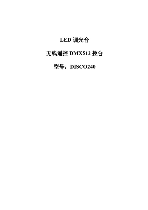
LED调光台无线遥控DMX512控台型号:DISCO240感谢选用我公司生产的DMX512控台(型号:DISCO 240),为了更好地使用和发挥DISCO 240电脑灯控制台的特点,在操作使用前,请仔细参阅说明书。
一参数指标二安全使用注意事项●控制台必须接安全大地线。
●应避免带电拨插通讯电缆。
●开机顺序:请先打开所有受控制的电脑灯电源,然后再打开控制器电源,否则易损坏控制器。
●注意防潮湿、防水、防尘、防静电,定期维护清洁。
三装箱清单DISCO 240控制台………………………1台电源线……………………………………1根5V电源适配器…………………………..1个无线DMX512发射器…………………..1个用户说明书………………………………1份产品合格证………………………………1份四安装方法●将无线DMX512发射器插入控制台背面卡侬座;●将5V电源适配器输出插头插入无线DMX512发射器电源插孔;●将5V电源适配器插入电源插板(AC220V);●将电源线输出插入控制台背面电源插座,输入插入电源插板(AC220V)。
五通讯电缆●采用特征阻抗为120欧双绞屏蔽线,如电缆超过200米或灯数量较多,应加信号放大器,并在最后一台灯加接终端电阻(100欧)。
●通讯电缆1脚为地(GND),2脚为信号正,3脚为信号负,在使用过程中不可接反接错。
●通讯电缆应单端接地屏蔽。
●通讯电缆应避免同强电一齐布线。
六D M X512地址分配DISCO 240控制台使用DMX512的1~240通道,其中1~192路为控制电脑灯用通道,可以控制16通道以内的电脑灯12台,从193开始为调光器用通道,地址分配如下:七通讯电缆连线及电脑灯地址码示意图注:当信号连接电缆过长时,需要加DMX信号放大器,并且在最后一台灯的信号座,加信号终端电阻(100欧)。
八面板及功能区域图九面板功能区域说明十双功能键区说明增加场景步十一L C D液晶屏显示信息说明【【十二电脑灯程序(场)的编辑1 按【BLACK】键,使该LED指示灯熄灭。
- 1、下载文档前请自行甄别文档内容的完整性,平台不提供额外的编辑、内容补充、找答案等附加服务。
- 2、"仅部分预览"的文档,不可在线预览部分如存在完整性等问题,可反馈申请退款(可完整预览的文档不适用该条件!)。
- 3、如文档侵犯您的权益,请联系客服反馈,我们会尽快为您处理(人工客服工作时间:9:00-18:30)。
2400L Wireless Controller
DMX512
USER MANUAL
VER: 2.0
This manual contains important information.
Please read before operating fixture
Product Profile:
DMX512 wireless receiver/transmitter transmit standard DMX512 protocol data by wireless way, which solve lighting control issues of wireless transmitting completely between console and lighting, lighting and lighting and so on, It get rid of connecting cable limited completely
And also can ensure without any time delay when signal data is transmitting, signal data is real time and reliably.
This product adopt global opening 2.4G ISM frequency section without permission limited
High effective GFSK modulate, communication design is 126 channels jumping frequency,high anti-jamming ability.
Application:
Stage lighting、Disco hall、Large literature performance、Gymnasium lighting、Temporary stage performance 、City lighting system 、TV station 、Conference center 、professional showplace、Topic park 、Bar lighting and so on.
Product Feature:
1. Product model:
2.4G DMX512 wireless receiver/transmitter
2. 2X8 bit LCD to display working condition and parameter
3. 4 grade power rate output for option.
4. 126 channels jumping frequency self-moving,self-moving to option
non-interfere frequency section, ensuring communication is reliable.
5. 16 groups ID coding for setting,User can use 16 groups individual
wireless net without any interfere each other in the same place.
6. Input voltage :9-12VDC 300MA MIN
7. Communication distance:400M(visible distance)
8. Working frequency:2.4G ISM,126 channels
9. Max transmitting power rate:20dBm
10. Receive sensitive:-94dBm
11. DMX single terminal:3PIN male-female socket Establishing Communication:
1. Power on DMX512 wireless receiver/transmitter
2. Press ”PRF UP” to set trans mitting power rate value,then press ”ID
UP” to set receiver and transmitter with same ID value。
Pay attention,
please use different ID value if you need use more than 1 group
wireless net at same time in same place.
3. This equipment start to option non-interfere frequency section for
transmitting signal data after received DMX signal data,receiver start to
change communicate frequency section,then Indicator lights of receiver
and transmitter will flash at same time,till received correct ID value.
4. Communication was established correctly then
Cauction:
✧Indoor use only.
✧ 1 year warranty, repairment, free replacement except damaged
artificially
✧The manufacturer willn’t offer free service in warranty period if any
repaired or uncapped had happened
✧It’s better to return to manufacturer if repairment is must, Don’t do any
repairment unless qualified electrician.
✧The working condition should be under temperature -20°C~+45°C,
10%~90%RH,no congelation,so as to ensure it’s lifetime。
✧It cann’t be covered by any superstr atum, it should be swept periodly to
prevent dust
12. Dimension :75X147X43 mm 13. Net weight :360g
Outline :
Front board
1:LCD display window 2:Indicator light of transmitting 3:Indicator light of receiver 4: Setting knob of transmitting power rate 5:ID Option Knob 6:Power
Switch
Back board
7: Power supply input jack 8:DMX Input Socket 9:DMX Output Socket 10:RF
Antenna
Display describing :
1. LCD display- - - - - - - - - - - - - - - - - - - - Include working condition 、
RF frequency 、transmitting power rate 、
ID coding etc.
2. Working condition- - - - - - - - “T”=TXD transmitting ”R”=RXD
receiving ”-“ =serching signal ,no setting needed when it warks
self-moving condition.
3. RF frequency- - - - - - - - - - - - - - - - - - 2. 400-2. 525 G ,Total 126
channels ,
no setting needed when it warks self-moving condition.
4. Transmitting power rate- - - - - - “0”=2dBm “1”=8dBm “2”=14dBm
“3”=20dBm ,Press ”PRF UP” for setting
5. ID Coding- - - -“0-F” 16 groups ID coding ,press”ID UP”setting ,Same ID
can communicate each other only.
Connecting Scheme :。