7884(74)(83)简明设置手册
5-AF788免治安装说明(新版)

報告單位:和成二廠生技課報告人:柯榮華規格:一.適用安裝於PF1/2配管.二.適用所有圓形馬桶三.適用水壓:0.7-5kg/cm2.四.適用電源:AF788:AC110V;AF788H:AC220V五.本產品可調整固定板來適用馬桶蓋長44公分和47公分兩種尺寸(後附說明).六.免治內部內藏漏電斷路器,若漏電時自動切斷電源,此時只要拔開插頭後重新插入插座即可重新啟動.七.和成免治沖洗馬桶座電路板皆具有防潮功能.八.產品台灣製造,品質服務皆可靠.免治整組外觀免治安裝前請先將馬桶及水箱零件安裝完成免治安裝前請先確認配件是否齊全免治左右包裝保利龍有安裝用零件請先取出後再丟棄保利龍(上圖保利龍內藏固定板及固定螺絲組)免治固定板取出,依上圖順序將螺絲組以手先預鎖緊在固定板上免治左右包裝保利龍有安裝用零件請先取出後再丟棄保利龍(上圖保利龍內藏30公分長高壓軟管及進水三通組)馬桶蓋固定孔為橢圓孔時馬桶蓋固定孔為圓孔時馬桶蓋固定孔為橢圓孔或圓孔皆可用此固定片安裝方向朝前方便免治卡住方向朝前方便免治卡住上圖固定板可調整不鏽鋼長型墊片位置以適用馬桶蓋長44公分馬桶不鏽鋼長型墊片不鏽鋼長型墊片上圖固定板可調整不鏽鋼長型墊片位置以適用馬桶蓋長47公分馬桶將固定板組對準馬桶座兩固定孔後壓入到底,再以十字螺絲起子將二支固定螺絲確實鎖緊再將免治底部凸槽對準固定板凹槽後推入到底卡住固定,此時可聽到”卡”一聲時,確定卡住確實將免治推入卡住使免治前緣與馬桶前緣切齊,若無法切齊則需鬆開固定板後重新調整前後鎖固位置將牆壁的三角凡而先以一字起子順時針鎖緊止水,若為舊馬桶加裝免治,則需拆除原舊進水高壓軟管將進水三通取出再將進水三通鎖入三角凡而出水牙部上(若因牆壁配管埋過深而造成三角凡而鎖入過深,使進水三通無法鎖在三角凡而時,也可將進水三通鎖在馬桶進水器下方牙部上)再將30公分長高壓軟管取出,一頭以活動板手鎖緊馬桶進水器牙部上AF788免治馬桶座安裝說明-9再將30公分長高壓軟管另一頭以再以活動板手鎖緊手預鎖在進水三通上方牙部上再將50公分長高壓軟管從包裝紙板上取出再將50公分長高壓軟管一頭以手預鎖在免治進水牙部上再以活動板手鎖緊再將50公分長高壓軟管另一頭以手先預鎖在進水三通側邊牙部上再以活動板手鎖緊再將牆壁的三角凡而以一字起子逆時針打開水源,使水流入免治,此時可查看各個零件接管處是否有漏水情形,若有漏水則需重新安裝漏水處再取出免治電源插頭並將插頭保護蓋拔出再將插頭確實依照適用電壓插入電源插座,注意絕不可將AC110V的免治插入AC220V插座,此舉將造成免治損壞AF788免治馬桶座濾網清潔若有噴水過小時,先將牆上三角凡而鎖緊止水,再用手或一字起子逆時針拆下免治進水下方的進水濾網,再以小刷子刷洗後以順時針裝回鎖緊,再打開三角凡而即可AF788免治馬桶座洩水開關若很久不使用免治而須拆下保存時,可先拔掉電源插頭後以前述方法反方向拆下免治,然後再逆時針拆下水箱洩水螺栓,洩完水後再順時針裝回鎖緊即可AF788免治馬桶座完成測試-1安裝完成後請測試前後噴水,溫水,暖座等調整功能,噴水測試前需持續按壓馬桶座右後方後鈕位置才可啟動噴水鈕噴水測試時需注意噴嘴伸出是否順暢自行測試完成需教導客戶如何使用AF788免治馬桶座完成測試-2並說明使用注意事項給客戶了解且須將安裝使用說明書,注意事項,保證書交給客戶保管參考免治內部內藏漏電斷路器,若漏電時免治會自動切斷電源,此時只要拔開插頭後重新插入插座即可重新啟動,若又自動切斷電源則需送回公司檢修,不可自行拆解維修THE END。
网格亚利安双频无线AC无线接入点WAC740设置指南说明书

InstallationWAC740Set Up the Access PointBefore mounting the access point in a high location, first set up and test the access point to verify WiFi network connectivity.IMPORTANT: You can deploy the WAC740 access point only in a WiFi network that is managed by a ProSAFE wireless controller.¾To cable the access point:1. Connect an Ethernet cable from LAN port 1 on the access point to aLAN port on a PoE+ switch, that is, an 802.3at-compatible switch.2. Connect an Ethernet cable from the PoE+ switch to an Ethernet port onthe computer.3. Check the LEDs to verify that the access point is set up correctly.Unpack the box and verify the contents:• WAC740 ProSAFE Dual Band Wireless AC Access Point • Category 5e Ethernet cable• Installation guide• Ceiling and wall installation kit• Ceiling and wall installation guide The access point uses a DHCP client that is enabled by default. If your network includes a DHCP server, the access point obtains an IP address from the DHCP server. If your network does not include a DHCP server, the access point sets its IP address to a static IP address of 192.168.0.160.If your network includes a DHCP server, note the following:• Make sure that Option 43 is enabled on the DHCP server.• Make sure that the DHCP server specifies the IP address of the wireless controller in the required hexadecimal format in the Option 43 field.For example, if the IP address of the wireless controller is 192.168.0.250, you must enter the hexadecimal string 02:04:C0:A8:00:FA.To compose the address, start with 02:04: and then add each of the four address octets in hexadecimal format, separated by colons.The first two octets (02:04) define a standalone NETGEAR wirelesscontroller, or in a stack, the first wireless controller in the stack.(Continued on the next page)July 2017© NETGEAR, Inc., NETGEAR and the NETGEAR Logo are trademarks of NETGEAR, Inc. Any non‑NETGEAR trademarks are used for reference purposes only.NETGEAR, Inc.350 East Plumeria DriveSan Jose, CA 95134, USANETGEAR INTL LTDBuilding 3, University Technology CentreCurraheen Road, Cork, IrelandTo specify the second wireless controller in the stack, enter the first two octets as 02:08. To specify the third wireless controller in the stack, enter the first two octets as 02:0C.The remaining four octets specify the IP address in hexadecimal format.• We recommend that you reserve an IP address for the access point onthe DHCP server.If your network does not include a DHCP server, configure a computer with a static IP address of 192.168.0.210 and a subnet mask of 255.255.255.0 so that you can connect to the access point at IP address 192.168.0.160. ¾To verify that the access point obtained IP address information,or if your network does not include a DHCP server, to configure the access point’s IP address information:1. Open a web browser from a computer that is connected to the samenetwork as the access point or to the access point directly through an Ethernet cable.2. In the address bar, enter the IP address of the access point.The default IP address is 192.168.0.160.A login window displays.3. Enter the user name and password.The user name is admin . The default password is password . The user name and password are case-sensitive.The Network Settings page displays. (The full path is Configuration > System > Network Settings .)4. In the IP Settings section, verify or configure the IP address informationfor the access point in the network.5. In the Controller Settings section, verify or configure the IP address forthe wireless controller in the network.6. Click the Apply button.Your settings are saved. For more information, see the ProSAFE wirelesscontroller user manual.SupportThank you for purchasing this NETGEAR product. You can visit /support to register your product, get help, access the latest downloads and user manuals, and join our community. We recommend that you use only official NETGEAR support resources.For more information about the installation options, visit /support to access the hardware installation guide.Si ce produit est vendu au Canada, vous pouvez accéder à ce document en français canadien à /other/.(If this product is sold in Canada, you can access this document in Canadian French at /other/.)For the current EU Declaration of Conformity, visit/app/answers/detail/a_id/11621/.For regulatory compliance information, visit /about/regulatory/.See the regulatory compliance document before connecting the power supply.¾To let the wireless controller discover the access point:1. Access the wireless controller at its network IP address.2. Select Access Point > Discovery Wizard .3. Follow the steps onscreen to discover the access point and review thediscovery results.4. In the table with discovered access points, select the check box for theaccess point, and click the Add button.The access point is added to the Managed AP List and is now ready for further configuration and management by the wireless controller. For more information, see the ProSAFE wireless controller user manual.Note: Make sure the country is set to the location where the device is operating. Thecustomer is responsible for complying within the local, regional, and national regulations set for channels, power levels, and frequency ranges .Deploy the Access PointThe best location for the access point is elevated, such as mounted on a wall or ceiling, at the center of the WiFi coverage area, and within line of sight of all mobile devices.For information about mounting the access point, see the ceiling and wall installation guide for the WAC720, WAC730, and WAC740 access points. ¾To deploy the access point:1. Disconnect the access point and position it where you will deploy it.2. Connect an Ethernet cable from the access point to a LAN port on aPoE+ switch.3. Make sure that the PoE+ switch and the wireless controller areconnected.4. Using a WiFi device, verify connectivity by connecting to the accesspoint and use a browser to connect to the Internet.Troubleshooting TipsThe following table provides some tips for correcting simple problems that you might encounter. For more troubleshooting information, see the ProSAFE wireless controller user manual.。
TL-R478+双wan口路由器使用说明书

双WAN口高速宽带路由器TL-R478+用户手册1910040125声明Copyright © 2010 深圳市普联技术有限公司版权所有,保留所有权利未经深圳市普联技术有限公司明确书面许可,任何单位或个人不得擅自仿制、复制、誊抄或转译本书部分或全部内容。
不得以任何形式或任何方式(电子、机械、影印、录制或其他可能的方式)进行商品传播或用于任何商业、赢利目的。
为深圳市普联技术有限公司注册商标。
本文档提及的其他所有商标或注册商标,由各自的所有人拥有。
本手册所提到的产品规格和资讯仅供参考,如有内容更新,恕不另行通知。
除非有特殊约定,本手册仅作为使用指导,本手册中的所有陈述、信息等均不构成任何形式的担保。
目录物品清单 (1)第1章用户手册简介 (2)1.1约定 (2)1.1.1图标的含义 (2)1.2用户手册概述 (2)第2章产品概述 (3)2.1产品简介 (3)2.2主要特性 (3)第3章硬件安装 (5)3.1面板布置 (5)3.1.1前面板 (5)3.1.2后面板 (6)3.2系统需求 (6)3.3安装环境 (6)3.4硬件安装步骤 (7)第4章快速安装指南 (8)4.1建立正确的网络设置 (8)4.2快速安装指南 (9)第5章配置指南 (12)5.1启动和登录 (12)5.2运行状态 (13)5.3设置向导 (14)5.4网络参数 (14)5.4.1LAN口设置 (14)5.4.2WAN口设置 (15)5.4.3WAN口在线检测 (20)5.4.4MAC地址克隆 (21)5.4.5负载均衡控制 (23)5.4.6ISP均衡控制 (26)5.4.7均衡策略 (27)5.4.8WAN端口参数 (28)5.5DHCP服务器 (29)5.5.1DHCP服务 (29)5.5.2客户端列表 (30)5.5.3静态地址分配 (30)5.6转发规则 (32)5.6.1虚拟服务器 (32)5.6.2特殊应用程序 (34)5.6.3DMZ主机 (35)5.6.4UPnP设置 (36)5.7安全设置 (37)5.7.1防火墙设置 (37)5.7.2IP地址过滤 (38)5.7.3域名过滤 (40)5.7.4MAC地址过滤 (42)5.7.5攻击防护 (43)5.8路由功能 (47)5.8.1静态路由表 (48)5.9连接数限制 (48)5.9.1连接数设置 (49)5.9.2连接数列表 (49)5.10QoS (50)5.10.1QoS设置 (50)5.10.2QoS规则 (51)5.11IP与MAC绑定 (52)5.11.1静态ARP绑定设置 (52)5.11.2IP与MAC扫描 (56)5.11.3ARP映射表 (56)5.12动态DNS (57)5.12.1花生壳DDNS (57)5.13交换机功能 (58)5.13.1端口统计 (59)5.13.2端口监控 (60)5.13.3端口流量限制 (60)5.13.4端口参数 (61)5.13.5端口状态 (62)5.14系统工具 (63)5.14.1时间设置 (63)5.14.2诊断工具 (64)5.14.3软件升级 (65)5.14.4恢复出厂设置 (65)5.14.5备份和载入配置 (66)5.14.6重启路由器 (68)5.14.7修改登录口令 (68)5.14.8系统日志 (69)5.14.9远端WEB管理 (69)5.14.10流量统计 (70)5.14.11IP地址转换表 (71)5.14.12NAT源端口设置 (71)附录A FAQ (73)附录B TCP/IP的详细设置 (76)附录C 技术参数表格 (77)物品清单请小心打开包装盒,里面应有以下配件:¾一台路由器¾一根电源线¾一本安装手册¾一张保修卡¾一张光盘¾两个L型支架及其它配件ᓖፀǖ如果发现有配件短缺或损坏的情况,请及时和当地经销商联系。
TP-Link无线路由器设置详细图解

登陆之后首先运行设置向导,这里寻修网/已经把登陆运行向导功能关闭,大家可以在左边栏点击设置向导。
点击下一步出现 ...由于本人现在是在办公室,属于在局域网内建设局域网(道理一样),所以先介绍静态ip的设置。
点击下一步出现 ...大家现在可以设置你的外网IP等信息,这个仅供有固定ip用户使用如果大家在上面选择的是pppoe设置(宽带拨号),则会弹出如上图的窗口,把你的帐号和pw输入点击下一步即可经过以上的设置之后,在前两个步骤点击下一步(如果选择的是动态ip则直接跳转到这里)都会跳转到如上图的窗 ...在模式这里可以选择带宽设置有11m、54m和108m共四个选项,只有11m和54m可以选择频段,共有1-13个频段供选择 ...完成后会出现如上图的所示,点击完成。
现在进入了网络参数设置的LAN口设置即你想组建的局域网网段,IP地址即你将要使用的网关IP地址设置好后,子网掩码有255.255.255.0和255.255.0.0可以选择.如果选择了255.255.255.0的话,最多可以使用 ...呵呵,这个wan口设置就是刚才咱们使用设置向导设置好的广域网(相对本局域网)信息大家应该看到了上图wan口连接类型有7个可供选择,根据自己的需要选择即可mac地址克隆就不需要详细介绍了吧,主要是外接设备需要绑定mac的时候,才需要更改为已允许的这个图片是无线参数的基本设置,这里主要说明的是安全设置,当然你要开启了才可以~~HOHO在这里可以添加允许或禁止的mac地址访问本局域网络,一般的家庭用的话,主机不多,建议启用允许列表即可,记 ...无线网络mac地址过滤设置,可以设置允许连接的网卡MAC,防止别人蹭网哦,很多朋友在寻修网/提问无线网络可以连接上,但是不能上网,就是因为无线路由器上设置了这一项。
本页显示的是连接到本无线网络的所有电脑的基本信息,用户可以在这里查看是否有别人的电脑挂在你的无线路由器上,有的话,可以试试改变设置,保护你的无线网络带宽。
诺基亚(Nokia) 7034 草图表面板说明书

LISTE DES PIÈCES PARTS LIST
IMAGE
DESCRIPTION
CROSSBAR BARRE TRANSVERSALE
QTY / QTÉ
1
CROSSBAR
12
1
BARRE TRANSVERSALE
CROSSBAR
13
1
BARRE TRANSVERSALE
FRONT PANEL
14
FRONT FACING RIGHT FRAME
8
1
CADRE AVANT DROIT
FRONT FACING LEFT FRAME
9
1
CADRE AVANT GAUCHE
CROSSBAR
10
1
BARRE TRANSVERSALE
PAGE 3 DE / OF 17
PIÈCE / PART #
11
I 7034
IMAGE
DESCRIPTION
CAP Ø5/8"
CAPUCHON Ø5/8"
PLASTIC BRACKET 1 1/2" x 3/4" x 3/4"
SUPPORT EN PLASTIQUE 1 1/2" x 3/4" x 3/4"
SPANNER Ø1/8"
CLÉ ANGLAISE Ø1/8"
SPANNER Ø1/4"
25
1
TIROIR
PAGE 6 DE / OF 17
PIÈCE / PART #
A B C D E
I 7034
LISTE DES PIÈCES DE MONTAGE HARDWARE LIST
思必拓SD80T(8464N)快捷使用指南说明书

快捷使用指南目录产品外观 (3)设备充电 (3)安装SIM卡 (4)开机、关机和重启 (4)通知栏 (5)连接WLAN (6)连接移动数据网络 (7)NFC (8)更改语言 (9)APN设置 (12)条码扫描注意事项 (13)恢复出厂设置 (15)开发支持 (17)产品参数 (17)包装清单 (18)常见问题 (19)联系我们 (19)产品外观设备充电第一次使用设备前,建议为设备充电。
1.请使用设备标配的充电器和USB(Type-C)数据线进行充电,否则可能无法启用快速充电模式,使用非原装充电器和USB充电线会影响电池寿命。
2.建议充电的同时不要使用设备,也不要在设备和充电器上覆盖其他物体导致设备发热。
3.设备处于低电量时,会有指示灯和系统提示,请尽快充电,以免影响正常使用。
4.设备长时间存放,请保证设备电池电量在百分之五十左右,并将设备置于干燥和适宜的环境中,避免长时间的存放导致设备损坏。
5.如遇电池、充电器,充电线损坏的情况,请停止使用并及时联系售后更换或购买相关配件,切勿自行修理,以免带来危险,造成额外损失。
安装SIM卡图1图21.使用T8规格螺丝刀将电池盖螺钉拧开,打开后盖。
2按照电池仓卡槽图示(图2),向对应位置插入相应卡即可。
开机、关机和重启1.设备关机状态下按住设备电源键2秒开机。
2.开机状态下按住电源键2秒以上,根据系统弹出菜单选择关机或重启。
3.设备异常无法操作,长按电源按键15秒以上,直到设备重启。
系统锁屏通知栏触摸屏幕顶端向下滑动打开通知栏,可点击各快捷功能图标打开关闭对应功能如WLAN、蓝牙等。
未处理的通知项,可以双击展开,触摸查看,也可以点按住左右滑动移除。
连接WLAN设置>>>网络和互联网>>>开启WLAN连接移动数据网络下拉通知栏点击移动数据如下图移动数据左上角显示小4G表示移动数据开启,可上网。
如下图移动数据左上角显示“X”表示移动数据关闭,不可上网。
PHILIPS 基本设置与返回说明文件说明书
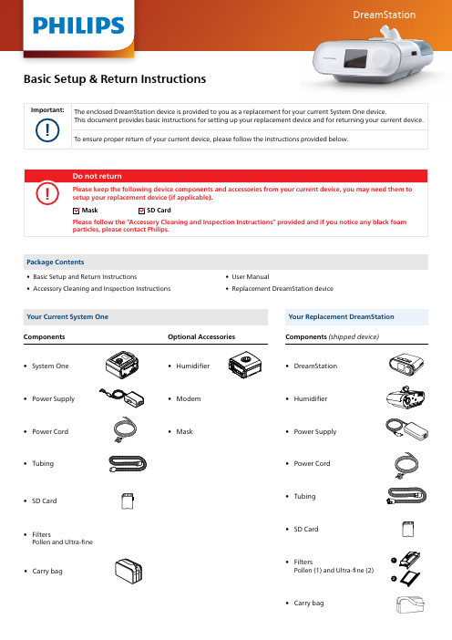
DreamStationBasic Setup & Return Instructions• Accessory Cleaning and Inspection Instructions • Replacement DreamStation deviceYour Current System OneYour Replacement DreamStation • System One • DreamStation• Humidifier • Modem • SD Card • SD Card• Carry bag• Carry bag • Filters Pollen and Ultra-fine• Filters Pollen (1) and Ultra-fine (2)• Mask • Power Supply • Power Supply• Humidifier• Power Cord • Power Cord• Tubing • TubingComponents Optional Accessories Components (shipped device)12Thank you for your cooperation in this effort.Visit .au/src-replacement-dreamstation-s1 for more information about your replacement device including video instructions. Please refer to the User Manual for more detailed information about the device and operation, including cleaning and adjusting your patient settings. Images may vary.For further assistance, please visit /src-update or contact Philips on 1800 830 517 in Australia (toll-free) or+61 2 9151 0289 in New Zealand selecting option 1, or your homecare provider.© 2022 Koninklijke Philips N.V. All rights reserved. Specifications are subject to change without notice. Trademarks are the property of Koninklijke Philips N.V. or their respective owners.PN UNS1RSPVersion: ANZ S1 10/2022v6Philips Sleep and Respiratory Care 65 Epping RoadNorth Ryde, NSW, 2113 Australia!O ur goods and services come with guarantees that cannot be excluded under the Australian and New Zealand Consumer Law. Your rights under the Australian and New Zealand Consumer Law are in addition to any remedy the local Philips entity may provide you.。
SCALANCEW788Configuration

SIEMENS
Getting Started SCALANCE W788 Configuration
图 1-2 没有 SCALANCE W788 的 Ad Hoc 网络 1.1.3 到有线 Ethernet 网络的无线通路 如果一个(或多个)SCALANCE W788 接入点(AP)连接到有线 Ethernet,下列应用 是可能的: • 唯一一个 SCALANCE W788 作为网关: 只有一个 Ethernet 网卡的计算机可以以客户端模式通过 SCALANCE W788 集成到无线 网络中。无线网络可以通过 SCALANCE W788 连接有线网络。 • 使用若干 SCALANCE W788 接入点扩展无线网络的无线覆盖范围: SCALANCE W788 接入点被组态成使用同一个 SSID(网络名)。所有希望通过这个网 络进行通讯的节点必须使用这个 SSID 组态。 如果移动站从一个 SCALANCE W788 的覆盖范围(cell)到另一个 SCALANCE W788 的覆盖范围(cell),无线连接能够维持(这称为漫游)。
上图中的硬件组成:
模块名称
模块型号
订货号
数量
工业无线局域网接入点 SCALANCE W788-1RR 6GK5 788-1SR00-2AA6 1
工业无线局域网接入点 SCALANCE W788-2RR 6GK5 788-2SR00-2AA6 1
电源
PS791-1PRO
7/37
SIEMENS
Getting Started SCALANCE W788 Configuration
图 1-5 使用四个 SCALANCE W788 的 WDS 实现 1.1.6 Redundant Wireless LAN (RWlan) RWlan 允许两个 SCALANCE W788-2xx 设备(W788-2PRO 或者 W788-2RR)之间的冗 余的无线连接。这被用来建立由于位置原因不能用有线网络实现而在可用性方面有高 要求的冗余无线主干。 有两种可选的组态是可能的。RWlan 搭档可以使用设备名或 MAC 地址来组态。
- 1、下载文档前请自行甄别文档内容的完整性,平台不提供额外的编辑、内容补充、找答案等附加服务。
- 2、"仅部分预览"的文档,不可在线预览部分如存在完整性等问题,可反馈申请退款(可完整预览的文档不适用该条件!)。
- 3、如文档侵犯您的权益,请联系客服反馈,我们会尽快为您处理(人工客服工作时间:9:00-18:30)。
北京天创信达科技发展有限公司
4. 在超级终端中测试: (4) 结束:退出超级终端。
北京天创信达科技发展有限公司
优化
交叉 25 码关闭检验:
(1) (2) (3) (4) (5) (6)
Reset Program mode 6 C D Save & reset
对交叉 25 码改为一遍扫描(加快速度)
(1) 2 (2) 0 (3) 5 (4) 4 (5) 1 (6) 1 (1) 1 (2) 6 (3) A (4) 2
(1) 2 (2) 3 (3) 1 (4) 0 (5) D (1) 1 (2) 4 (3) A (4) 1 (1)1 (2)7 (3)A (4)1 (1)1 (2)5 (3)1 (4)1 (5)1 (6)8 (7)1 (8)8 (9)0
1. 打开 com2key,选择 com1
2. 此时界面如下,不用再点任何按钮。
3. 扫描条码:打开一个文本文档后就可以用 NCR 平台进行扫描测试。
北京天创信达科技发展有限公司
4. 结束: 按 com2key 的结束键,退出文本文档。 (2)用超级终端测试
1. 打开超级终端:
2. 建立新链接:
3. 设置 COM 口,如下:
(1) 6
(2) C
(3) D
Save and Reset
北京天创信达科技发展有限公司
根据上表,扫描对应的设置条签,即可。
设置条码签
Reset
Default
Program mode
Abort
Save and reset
HEX 0
北京天创信达科技发展有限公司
HEX 1
HEX 2
HEX 3
HEX 4
北京天创信达科技发展有限公司
NCR RealScan 7884(7874/83)设置方法
连接协议:RS232(串口): RS232(串口)参数设置: 去前缀设置: 去后缀设置: 39 码设置: 128 码设置: 交叉 25 码设置:
保存退出
(1) (2) (3) (4) (5) (6)
Reset Default Programming Mode 1 0 5
(1) (2) (3) (4) (5) (6) (7)
Reset Program mode 6 B 5 1 Save &Reset
设置EAN、UPC-A的前导 0
(1) Reset (2) Program mode (3) 1 (4) 3 (5) 1 (6) 0 (7) 1 (8) 0 (9) 0 (10) Save &Reset
HEX 5
北京天创信达科技发展有限公司
HEX 6
HEX 7
HEX 8
HEX 9
HEX A
北京天创信达科技发展有限公司
HEX B
HEX C
HEX D
HEX E
HEX F
北京天创信达科技发展有限公司
END
北京天创信达科技发展有限公司
测试
(1) 用 com2key.exe 测试 Com2Key.exe 或者 comtoKey.exe 是用来进行 RS232 通信测试的软件,可以在网上下载。 指对 NCR 的扫描平台,可按下列步骤测试: