ABB ACS550-01用户手册
ACS550变频器说明书(中文版)
Drive IT 低压交流传动用户手册ACS550-01 变频器 (0.75...90 kW)2ACS550 用户手册ACS550 变频器手册通用手册ACS550-01/U1 用户手册 (0.75…90 kW) / (1…150HP)•安全指南•安装•起动•诊断•维护•技术数据ACS550-02/U2 用户手册 (110…355 kW) / (150…550 HP)•安全指南•安装•起动•诊断•维护•技术数据ACS550 技术参考手册•详细产品描述–产品技术描述,包括外形尺寸图–柜体安装信息,包括功率损耗–软件和控制包括完整参数描述–用户接口和控制连接–完整可选件描述–备件–其它等•实际工程指导–PID & PFC 工程指导–安装和选型指导–诊断和维护信息–其它等可选件手册( 现场总线适配器, I/O 扩展模块等,手册和可选件一起发货 )继电器输出扩展模块•安装•起动•诊断•技术数据ACS550 用户手册3安全指南警告! 只有专业技术人员才允许安装 ACS550!警告! 即使电机已经停止, 功率端子 U1, V1, W1和 U2, V2, W2 以及UDC+, UDC-或 BRK+ , BRK- 上面依然存在危险电压!警告!主回路电源得电后即存在危险电压。
电源断开后等候5分钟(让中间回路电容充分放电)再打开前面板。
警告!ACS550断电后,在继电器端子上 ( R01…R03 )依然可能有外部危险电压。
警告! 当两个或两个以上的变频器的控制端子并联使用时,用于控制连接的辅助电源应来自同一个单元或外部电源。
警告! ACS550-01/U1不是可以在现场维修的机器。
不要试图修理损坏的单元,请与供应商或当地授权的维修站联系。
警告! 当输入电源短时断电之后再次恢复时,如果外部运行指令为ON,ACS550 将自动起动。
警告! 散热器的温度可能很高。
参见127页的“技术数据”。
警告!如果变频器用在浮地电网时,请拆下螺钉EM1和EM3(外形尺寸R1…R4)或F1和F2(外形尺寸 R5 或R6)。
ACS550用户使用手册.

ACS550 用户使用手册纸189页嵌入式现场总线概览设立的ACS550能够使用标准的串行通信协议从外部系统接受控制。
当使用串行通讯时,ACS550能够做到下面的事情:从现场总线接受所有的控制信息或者被总线控制的集合体和其他可用的控制路径所控制,例如数字或模拟的投入和控制面板。
两个基本串行通信可被配置嵌入式现场总线-----采用RS485接口使用在终端X1:28….32上的控制板,一种控制系统通信网的驱动器使用的Modbus 协议。
(对于协议和外形的描述,参见这一章后面的Modbus 协议电子数据和ABB 控制配置文件技术数据两部分)现场总线适配器-----参见221页现场总线适配器章节。
控制接口总体上, Modbus 和驱动器之间的基本控制接口包括下面的部分:输出字---控制字---参考资料1---参考资料2输入字---状态字---实际价值1---实际价值2纸190页---实际价值3---实际价值4---实际价值5---实际价值6---实际价值7---实际价值8这些字的内容被概况定义了,关于使用的概况的细节参见209页ABB 控制配置文件技术数据部分。
说明:关于字输入和输出的使用是从现场总线控制器的角度看的,例如输出描述数据流从现场总线控制器到驱动器,从驱动器的角度显示的是输入。
规划网络规划应解决下列问题:什么类型和数量的设备必须是连接到网络?什么控制信息必须设置到驱动器?什么反馈信息必须送交从驱动器的控制系统?机械和电气安装----嵌入式现场总线警告!连接应该只在驱动器断开电源时。
驱动器终端28….32是为了RS485通信。
使用贝尔登9842或相等物。
贝尔登9842是一种扭曲的,对屏蔽电缆的波阻抗是120欧姆。
在使用上述其中一种双屏蔽双绞线的485链接。
使用此对连接所有A (- )终端一起和所有B(+ )终端在一起。
使用一个电线在其他两个的逻辑地面(终端31 ),造成一个电线使用。
在任何时候不直接连接地面485网络。
ABB ACS550-01, IP21 UL Type 1, Quick Start 说明书
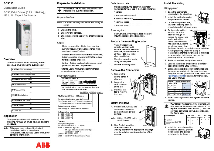
ACS550Quick Start GuideACS550-01 Drives (0.75…160 kW),IP21 / UL Type 1 EnclosureOverviewThe installation of the ACS550 adjustablespeed AC drive follows the outline below.ApplicationThis guide provides a quick reference forinstalling ACS550-01 drives having a standard enclosure.Note:This guide does not provide detailedinstallation, safety or operationalinstructions. See ACS550 User’s Manual forcomplete information.Prepare for installationWARNING! The ACS550 should ONLY beinstalled by a qualified electrician.Unpack the driveNote:Lift the ACS550 by its chassis and not by its cover.1.Unpack the drive.2.Check for any damage.3.Check the contents against the order / shippinglabel.Check•Motor compatibility – Motor type, nominalcurrent, frequency and voltage range mustmatch drive specifications.•Suitable environment – Drive requires heated,indoor controlled environment that is suitablefor the selected enclosure.•Wiring – Follow local codes for wiring, circuitprotection and EMC requirements.Refer to User’s Manual and confirm that allpreparations are complete.Drive identificationUse the following chart to interpret the type code found on the drive label.Collect motor dataCollect the following data from the motornameplate for later use in the ACS550 startup:•Voltage __________________________•Nominal motor current ______________•Nominal frequency _________________•Nominal speed ____________________•Nominal power ____________________Tools requiredScrewdrivers, wire stripper, tape measure,mounting screws or bolts and drill.Prepare the mounting locationThe drive requires asmooth, vertical, solidsurface, free from heat andmoisture, with free space forair flow – 200mm (8in)above and below.1.Mark the mounting pointsusing the template.2.Drill the mounting holes.Remove the front cover1.2.3.Mount the drivewarning sticker in the appropriate languageover the existing warning on the top of themodule.Install the wiringWiring power1.Open the appropriateknockouts in the gland box.2.Install the cable clamps forthe power/motor cables.3.On the input power cable,strip the sheathing back farenough to route individual wires.4.On the motor cable,strip the sheathingback far enough toexpose the copper wireshield so that theshield can be twistedinto a bundle. Keep thebundle not longer thanfive times its width to minimize noise radiation.– 360° grounding under the clamp isrecommended for the motor cable to minimizenoise radiation. In this case, remove thesheathing at the cable clamp.5.Route both cables through the clamps.6.Connect the bundle created from the motorcable shield to the GND terminal.7.Strip and connect the power/motor wires andthe power ground wire to the drive terminalsusing the torques given in the table below. SeePower connections below or, for more detail,see User’s Manual.8.Install conduit/gland box and tighten the cableclamps.WARNING! To disconnect the internal EMCfilter, remove the screws marked with “-”, orreplace the screws marked with “” with theprovided polyamide screws, depending onthe frame size.9.Install the cable clamp(s) forthe control cable(s). (Power/motor cables and clampsnot shown in the figure.)PREPARE for installation PREPARE mounting location REMOVE the front coverMOUNT the drive INSTALL wiring CHECK installation REINSTALL the cover APPLY power START-UPSernoACS550-01-08A8-4*2030700001*U1 3~ 380...480 VI2N/ I2hd 8.8/6.9 APN/Phd 4.0/3.0 kWACS550-01-08A8-4+J404+…AC, Standard Drive – 550 seriesSee Ratings in User’s Manual for detailsConstruction (region specific)Output current ratingVoltage rating2=208…240V AC4=380…480V AC6=500…600V ACExamples of options:No specification=IP21 / UL type 1B055=IP54 / UL type 12UL type 12 is not available for typeACS550-01-290A-4.0J400=No control panelJ404=ACS-CP-C Basic Control Panel01=Setup/parts for IEC install./complianceU1=Setup/parts for US install./complianceOptionsFramesizeTightening torqueN·m lb·ftR1, R21.41R3 2.5 1.8R4 5.6; PE: 24; PE 1.5R51511R640; PE: 830; PE: 6System type R1...R3R4R5...R6EM1EM3EM1EM3F1F2IT system----Corner grounded TNsystem-Wiring the controls1.Strip control cable sheathingand twist the copper shield into a bundle. 2.Route control cable(s)through clamp(s) and tighten clamp(s). 3.Connect the ground shieldbundle for digital and analog I/O cables at X1-1. (Ground only at the drive end.)4.Strip and connect the individual control wires to the driveterminals. Use a tightening torque of 0.4 N·m (0.3 lb·ft). See Control connections below or, for more information, see User’s Manual . 5.Install the conduit/gland box cover (1screw).Control connectionsNote 1.Jumper setting (two switch types possible):Note 2. Code: 0=open, 1=connectedWARNING! The maximum voltage for digital inputs is 30 V.Check installationBefore applying power, perform the following checks.Reinstall the cover1.Align the coverand slide it on. 2.Tighten the captive screw. 3.Install the controlpanel.Apply powerAlways reinstall the front cover before turning power on.WARNING! The ACS550 will start upautomatically at power up, if the external run command is on.1.Apply input power.When power is applied to the ACS550, the green LED comes on.Note: Before increasing motor speed, check thatthe motor is running in the desired direction.Start-upIn start-up, enter motor data (collected earlier) and, if needed, edit parameters that define how the drive operates and communicates.Assistant Control PanelThe Start-up Assistant steps through typical start-up selections, and runs automatically upon the initial power up. At other times, use the steps below to run the Start-up Assistant.For common parameters and menu items,use the Help key to display descriptions.If you encounter alarms or faults, use the Help key or refer to chapter Diagnostics in User’s Manual .Basic Control PanelThe Basic Control Panel does not include the Start-up Assistant. Refer to section How to start up the drive in User’s Manual and manually enter any parameter changes desired.(U2, V2, W2)(U1, V1, W1)(U2, V2, W2)(U1, V1, W1)Frame size R6Optional brakingFrame size TerminallabelsBrake options R1, R2BRK+, BRK-Brake resistor R3…R6UDC+, UDC-•Braking unit•Chopper and resistorbraking below.below.DI3DI4Output 00Reference through AI110CONSTANT SPEED 1 (1202)01CONSTANT SPEED 2 (1203)11CONSTANT SPEED 3 (1204)1SCR 2AI13AGND 410V 5AI26AGND 7AO18AO29AGND 1024V 11GND 12DCOM 13DI114DI215DI316DI417DI518DI619RO1C 20RO1A 21RO1B 22RO2C 23RO2A 24RO2B 25RO3C 26RO3A 27RO3BExt. freq. ref. 1: 0…10V Output freq.: 0…20mA Start/Stop: Active = start Fwd/Rev: Active = rev. dir.Constant speed sel.2Constant speed sel.2Ramp pair: Active = 2nd ramp pair.Relay output 1Default operation:Relay output 2Default operation:Relay output 3Default operation:X1Output current: 0…20mA Not usedAnalog input com. Not usedAnalog output com.Aux. volt. commonDigital input com. for all Analog input com.Ready = 19/21 connected Running = 22/24 connected Fault(-1) =25/27 connected (Fault => 25/26 connected)Ref. voltage 10V DC Aux. volt. output +24V DC ABB Standard macroSignal cable shield (screen)J1AI1: 0 (10V)AI2: 0(4)…20mAONONON12or J1CheckEnvironment conforms to specifications.The drive is mounted securely.Proper cooling space around the drive.The motor and driven equipment are ready for start.For IT systems and corner grounded TN systems: The internal EMC filter is disconnected (see the table in Wiring power ).The drive is properly grounded.Input power (mains) voltage matches the drive nominal input voltage.The input power (mains) terminals, U1, V1, W1, are connected and tightened as specified.The input power (mains) fuses are installed.The motor terminals, U2, V2, W2, are connected and tightened as specified.Motor cable is routed away from other cables.NO power factor compensation capacitors are in the motor cable.Control terminals are wired and tightened as specified.NO tools or foreign objects (such as drill shavings) are inside the drive.NO alternate power source for the motor isconnected – no input voltage is applied to the output of the drive.?C o d e : 3A F E 68243513 R E V E / E NE f f e c t i v e : 2009-07-07S u p e r s e d e s : 2007-04-16。
ABB ACS550 一般目的电机驱动器产品系列说明书

Phone: 033 22356676***********************************Low voltage AC drivesABB general purpose drivesACS5500.75 to 355 kW/1 to 500 hpCatalogType designation:Product seriesRating and types Voltages Construction DimensionsOptions ACS550–01–03A3–4+B055Selecting and ordering your driveBuild up your own ordering code using the type codekey below or contact your local ABB drives salesoffice and let them know what you want. Use page 3as a reference section for more information.2 ABB general purpose drives ACS550 | CatalogContentsABB general purpose drives, ACS550Catalog | ABB general purpose drives ACS550 34 ABB general purpose drives ACS550 | CatalogABB general purpose drivesABB general purpose drives are simple to buy, install, configure and use, saving considerable time. They are widely available through ABB channel partners. The drives have common user and process interfaces with fieldbuses, common software tools for sizing, commissioning, maintenance and common spare parts.ApplicationsABB general purpose drives can be used in a wide range of industries. Typical applications include pump, fan and constant torque use, such as conveyors. ABB generalpurpose drives are ideal in those situations where there is a need for simplicity to install, commission and use and where customizing or special product engineering is not required.Introduction to ACS550Highlights−FlashDrop tool−Intuitive use with assistant control panel−Swinging choke for superior harmonic reduction −Vector control−Coated boards for harsh environments−Built-in category C2 EMC filter (1st environment) as standard−Flexible fieldbus system with built-in Modbus and numerous internally mountable fieldbus adapters−UL, cUL, CE, C-Tick and GOST R approved −RoHS compliantFeature Advantage BenefitEnergy efficiency counters Several counters to illustrate saved energy (kWh), carbondioxide emissions (CO 2) and cost in local currency.Shows direct impact on energy bill and helps control operational expenditure (OPEX).Load analyzerLoad analyzer saves process data, such as current and torque values, which can be used to analyze the process and dimensioning of the drive and motor.Optimized dimensioning of the drive, motor and process.FlashDrop tool Faster and easier drive set-up and commissioning.Patented, fast, safe and trouble-free parametrization method without electricity.Assistant control panelTwo soft-keys, function of which changes according to the state of the panel.Built-in help function via dedicated button.Real-time clock, allows timed tracing of faults and setting of parameters to activate at various times of day.Changed parameters -menu.Easy commissioning.Fast set-up.Easier configuration.Rapid fault diagnosis.Quick access to recent parameter missioning assistantsPID controller, real-time clock, serial communications assistant, drive optimizer, startup assistant.Easy set-up of parameters.Maintenance assistant Monitors consumed energy (kWh), running hours or motor rotation.Takes care of preventative maintenance of drive, the motor or run application.Intuitive featuresNoise optimization.Increases switching frequency of drive when drive temperature is reduced.Controlled cooling fan: the drive is cooled only when necessary.Considerable motor noise reduction.Reduces inverter noise and improves energy efficiency.Choke Patented swinging choke - matches the right inductance to the right load, thereby suppressing and reducing harmonics.Reduces total harmonic distortion (THD) emissions up to 25%.Vector control Improved motor control performance.Enables wider range of applications.Built-in EMC filter Category C2 (1st environment) and category C3 (2nd environment) RFI filters as standard.No need for additional external filtering.Brake chopper Built-in up to 11 kW.Reduced cost.ConnectivityBuilt-in Modbus using EIA-485.Simple to install:–Easy connection of cables–Easy connection to external fieldbus systems through multiple I/Os and plug-in optionsReduced cost.Reduced installation time.Secure cable connections.Mounting template Supplied separately with unit.Quick and easy to mark mounting screw holes on installation surface.RoHS compliantACS550 drives comply with EU Directive RoHS 2002/95/CE restricting the use of certaing hazardous substances.Environmentally friendly product.ACS550–01–03A3–4+B055Technical dataACS550–01–03A3–4+B055Low Voltage Directive 2006/95/ECEMC Directive 2004/108/ECQuality assurance system ISO 9001Environmental system ISO 14001UL, cUL, CE, C-Tick and GOST R approvalsRoHS compliantCatalog | ABB general purpose drives ACS550 5Ratings, types, voltages and constructionType designationDrive’s type designation (shown above and in column 7 of thetables on the right side) identifies your drive by construction,current rating and voltage range. Once you have selected thetype designation, the frame size (column 8) can be used todetermine the drives dimensions, shown on the next page.Construction“01” within the type designation (shown above) variesdepending on the drive mounting arrangement, and powerrating.01 = wall-mounted02 = free-standingVoltagesThe ACS550 is available in two voltage ranges:4 = 380 to 480 V2 = 208 to 240 VInsert either “4” or “2”, depending on your chosen voltage,into the type designation shown above.Normal use vs heavy-duty use. For the majority of pump, fan and conveyorapplications, select “Normal use” fi gures. For high overload requirements, select“Heavy-duty use” fi gures. If in doubt contact your local ABB sales offi ce or yourdrives distributor.PNfor kW = Typical motor power in 400 V at normal usePNfor hp = Typical motor power in 460 V at normal usePhdfor kW = Typical motor power in 400 V at heavy-duty usePhdfor hp = Typical motor power in 460 V at heavy-duty useI 2N for A = Continuous rms current. 10% overload is allowed for one minute in ten minutes.I 2hd for A = Continuous rms current. 50% overload is allowed for one minute in tenminutes.3-phase supply voltage 380 to 480 VWall-mounted unitsFree-standing units200300368160250302ACS550-02-368A-4R8250400486200350414ACS550-02-486A-4R8280450526250400477ACS550-02-526A-4R8315500602280450515ACS550-02-602A-4R8355500645315500590ACS550-02-645A-4R83-phase supply voltage 208 to 240 VWall-mounted unitsACS550–01–03A3–4+B0556 ABB general purpose drives ACS550 | CatalogCatalog | ABB general purpose drives ACS550 7DimensionsElectromagnetic compatibilityThe EMC product standard (EN 61800-3 + Amendment A11[2000]) covers the specific EMC requirements stated for drives (tested with motor and cable) within the EU. The new revision of 61800-3 (2004) product standard can be applied from now on, but latest from 1st October 2007. EMC standards such as EN 55011, or EN 61000-6-3/4, apply to industrial and household equipment and systemsincluding drive component inside. Drive units complyingWall-mounted unitsFree-standing unitsWall-mounted drives Free-standing drives EMC according to EN61800-31stenvironment restricted distribution for frame sizes R3, R4 with75 m motor cables and for frame sizes R1, R2, R5, R6 with 100 m motor cables as standard.2ndenvironment unrestricted distribution for frame sizes R1 to R4 with300 m motor cables and for frame sizes R5 to R8 with 100 m motor cables as standard.These cable lengths are for EMC purposes only. Operational cable lengths are available in the output choke selection table on page 11.For longer motor cable lengths, external EMC filters are available onrequest.EMC standards in general1)The dimensions apply to bookshelf mounting. In fl at type mounting the width anddepth change places. n/a = not applicablezH1 = Height with cable connection box H2 = Height without cable connection box W = Width D = Depthwith requirements of EN 61800-3 are always complient with comparable categories in EN 55011 and EN 61000-6-3/4, but not necessarily vice versa. EN 55011 and EN 61000-6-3/4 do not specify cable length nor require a motor to be connected as a load. The emission limits are comparable according to the following table, EMC standards.WH1DH2DWH11) ACS550-01-246A-4 and ACS550-01-290A-4: 979 mm 2)UL Type 12 not available for ACS550-01-290A-43)ACS550-01-290A-4: 1119 mmACS550–01–03A3–4+B0558 ABB general purpose drives ACS550 | CatalogAssistant control panelThe assistant control panel, which is delivered as standard, features a multilingual alphanumeric display for easy drive programming. The control panel has various assistants and a built-in help function to guide the user. It includes a real time clock, which can be used during fault logging and in controlling the drive, such as start/stop. The control panel can be used for copying parameters for back up or fordownloading them to another drive. A large graphical display and soft keys make it extremely easy to navigate.OptionsControl interfacesPanel mounting kitsTo attach the control panel to the outside of a larger enclosure, two panel mounting kits are available. A simple and cost-efficient installation is possible with the ACS/H-CP-EXT kit, while the OPMP-01 kit provides a more user-friendly solution, including a panel platform that enables the panel to be removed in the same way as a drive-mounted panel. The panel mounting kits include all hardware required, including 3 m extension cables and installation instructions.ACS550–01–03A3–4+B055ACS550–01–03A3–4+B0551) Ordering with a separate material code number.2)One slot available for relay or encoder.3)One slot available for fieldbus adapter. Modbus built-in as standard.Available optionsHow to select optionsThe options shown in the table are available within the ACS550 range. Most of them have an associated 4-figure option code, which is shown in the table. It is this code that replaces B055 in the type code above. External options require a separate order line and material or type code number.Basic control panelThe basic control panel features a single line n umeric display. The panel can beused to control the drive, set the parameter values or copy them from one drive to another.Catalog | ABB general purpose drives ACS550 9Plug-in optionsFlashDrop toolRelay output extension option modulecomponents in the system.Encoder feedback option modulePlug-in fieldbus moduleincreasing system reliability.−DeviceNet TM −LonWorks ®−PROFIBUS DP −CANopen ® −ControlNet −Modbus TCP −EtherNet/IP TM −PROFINET IO −PowerLink−EtherCAT ®For type codes see page 8ACS550–01–03A3–4+B05510 ABB general purpose drives ACS550 | CatalogExternal optionsFlashDrop toolFlashDrop is a powerful palm sized tool for fast and easy parameter selecting and setting. It gives the possibility to hide selected parameters to protect the machine. Only the parameters needed in the application are shown. The tool can copy parameters between two drives or between a PC and a drive. All the above can be done without a power connection to the drive. The interface for FlashDrop is available in all wall-mounted units.DrivePMDrivePM (drive parameter manager) is a tool to create, edit and copy parameter sets for the FlashDrop tool. For each parameter/group the user has a possibility to hide it, which means that the drive user does not see the parameter/group at all.DrivePM requirements−Supported operating systems: Windows NT/2000/XP/Vista FlashDrop package includes −FlashDrop tool−DrivePM software (CD-rom)−User’s manual (hardcopy and PDF)−RS232 cable for connection between PC and the FlashDrop tool −Battery chargerDriveWindow LightDriveWindow Light is an easy-to-use startup and maintenance tool for ACS550 drives. It can be used in an offline mode, which enables parameter setting at the office even before going to the actual site. The parameter browser enables viewing, editing and saving of parameters. The parameter comparison feature makes it possible to compare parameter values between the drive and the file. With the parameter subset you can create your own parameter sets. Controlling of the drive is naturally one of the features in DriveWindow Light. With this software tool, you can monitor up to four signals simultaneously. This can be done in both graphical and numerical format. Any signal can be set to stop the monitoring from a predefined level.Startup wizardsStartup wizards make the setting of parameters easy. Simply launch the wizard, select an appropriate assistant eg, for setting analog outputs, and all parameters related to this function are shown together with help pictures.Highlights−Editing, saving and downloading parameters −Graphical and numerical signal monitoring −Drive control −Startup wizardsDriveWindow Light requirements−Supported operating systems: Windows NT/2000/XP/VistaSREA-01 Ethernet adapter SREA-01 Ethernet adapter with remote monitoring access can send process data, data logs and event messagesindependently, without a PLC or a dedicated on-site computer. It has an internal web server forconfiguration and drive access.Catalog | ABB general purpose drives ACS550 11OptionsExternal optionsBrake units and choppersFrame sizes R1 to R2 are delivered with integrated brakechoppers as standard. Other units can use the compact-sized brake units which include brake chopper and resistor. For more information please refer to the ACS-BRK brake units installation and startup guide.HWDBrake units technical dataDimensions1)The last digit of the output choke type defi nes the degree of protection; X stands for 2 = IP22 or 5 = IP54, 0 = IP002)Cable lengths according to 4 kHz switching frequency 3)Maximum switching frequency to be used with du/dt fi lter is 4 kHz Output chokesOutput chokes are used when motor cables above normal length are required.Cable can be roughly 1.5 times standard cable length, see below.Note:An output choke does not improve the EMC performance of the drive. To fulfi l local EMC requirements use suffi cient RFI fi ltering.For more information refer to the ACS550 User’s manual /Technical reference.12 ABB general purpose drives ACS550 | CatalogCooling and fusesCoolingACS550 is fitted with cooling air fans. The cooling air must be free from corrosive materials and not above the maximum ambient temperature of 40 °C (50 °C with derating). For morespecific environmental limits see page 5.Cooling air flow 380 to 480 V unitsCooling air flow 208 to 240 V unitsFuse connectionsStandard fuses can be used with ABB general purpose drives.For input fuse connections see tables below.Free space requirementsRecommended input protection fuses for 380 to 480 V unitsRecommended input protection fuses for 208 to 240 V units*)According to IEC-60269 standardControl connectionsThese connections are shown as examples only. Please refer to the ACS550 User’s manual, chapter Installations, for more detailed information.1 SCR2 AI13 AGND4 +10V5 AI26 AGND7 AO18 AO29 AGND10 +24V11 GND12 DCOM13 DI114 DI215 DI316 DI417 DI518 DI619 RO1C20 RO1A21 RO1B DIP switch analog inputs0 - 20 mAGround the cable screen on the sourcing endramp pair sel.const.speed 1fwd/revstart/stopDI configuration NPN connected (sink)EIA-485Multidrop applicationOther ModbusdeviceSCRBAGNDBAGNDSCRACS550X3ACS550X1ACS550X1DIP switchanaloginputsDI configurationPNP connected(source) withexternalpower supplyDIP switchEIA-485interfaceSignal termination isselected by DIP switchNottermin.22 RO2C23 RO2A24 RO2B25 RO3C26 RO3A27 RO3B28 SCR29 B30 A31 AGND32 SCR25 RO3C26 RO3A27 RO3B22 RO2C23 RO2A24 RO2B19 RO1C20 RO1A21 RO1B10 +24V11 GND12 DCOM13 DI114 DI215 DI316 DI417 DI518 DI61 SCR2 AI13 AGND4 +10V5 AI26 AGND7 AO18 AO29 AGNDconst.speed 1fwd/revstart/stop+ 24V0-10 V0-10 V0-10 V0(4)-20 mAAI1:AI2:NONONONONONOAI1:+ 0V-AI2:R<10 kΩR<10 kΩCatalog | ABB general purpose drives ACS550 1314 ABB general purpose drives ACS550 | CatalogExpertise at every stage of the value chainSecure uptime throughout the drive life cycleWhether you operate in industry, commerce or a utility your aims remain the same: to keep your motor-driven applications running consistently and efficiently. The life cycle services for ABB drives can help you achieve these aims by maximizing the uptime of your process while ensuring the optimum lifetime of ABB drives in a predictable, safe and low-cost manner.ABB follows a four-phase model for the life cycle management of its drives. The life cycle phases are active, classic, limited and obsolete. Within each phase, every drive series has a defined set of services.ABB drive life cycle management modelPrepurchaseOrder and delivery Installationandcommissioning Operation andmaintenance Upgrade and retrofit Replacementand recyclingTraining and learning Technical supportContractsThe life cycle services for ABB drives span the entire value chain, from the moment you make the first enquiry about a drive through to its disposal and recycling. Throughout the value chain, ABB provides training and learning, technical support and contracts. All of this is supported by one of the most extensive global drive sales and service networks.The four-phase drive life cycle management model provides you with a transparent method for managing your investment in drives. In each phase, you clearly see what life cycle services are available, and more importantly, what services are not available. Decisions on upgrading, retrofitting or replacing drives can be made with confidence.The drive, with complete life cycle services, is available for purchase.The drive, with complete life cycle services, is available for plant extensions.Spare parts, maintenance and repair services are available as long as materials can be obtained.ABB cannot guarantee availability of life cycle services for technical reasons or within reasonable cost.Complete life cycle servicesLimited life cycle servicesTo ensure the availability of complete life cycle services, a drive must be in the active or classic phase. A drive can be kept in the active or classic phase by upgrading, retrofitting or replacing.Caution! A drive entering the limited or obsolete phase has limited repair options. This may result in unpredictable process downtime. To avoid this possibility, the drive should be kept in the active or classic phase.Active Classic Limited ObsoleteNotesCatalog | ABB general purpose drives ACS550 153A F E 64792857 R E V P E N 26.3.2014 #17067© Copyright 2014 ABB. All rights reserved. Specifi cations subject to change without notice.Contact Details:Industrial Supply Syndicate54, Ezra Street, Kolkata - 700 001, INDIAPhone: 22350923, 22356676 Fax: +91 33 3022 2923Email:*******************************:。
ACS550用户手册
警告 ! 不要使用断路设备来起停电机,而应通过控制变频器的起停来控制电机。直流 侧电解电容所允许的最大充放电次数为每 10 分钟内 5 次。 警告!如果变频器用在浮地电网或高阻接地(大于30欧姆)电网时,请断开内部EMC滤 波器的连接,否则系统将通过 EMC 滤波电容接地。可能会导致危险或损坏变频器。 如果变频器用在角接地 TN 电网时,请断开内部 EMC 滤波器的连接,否则将损坏变 频器。 注意断开 EMC 滤波器连接后,变频器将不具有 EMC 兼容性。 参见相关章节 " 断开内部 EMC 滤波器 ",第 17 页。也参见相关章节 " 不对称接地电 网、 " 和 " 浮地电网 ",第 232 页。 警告 ! 不要试图在变频器上电的时候安装或拆卸 EM1, EM3, F1 或 F2 螺钉。
RECA-01 EtherCAT 总线适配器用户手册 3AUA0000043520 ( 英文 )
REPL-01 Ethernet POWERLINK 总线适配器用户手册 3AUA0000052289 ( 英文 )
ACS550 User’s Manual
RETA-01 Ethernet 总线适配器用户手册 3AFE64539736 ( 英文 ) RETA-02 Ethernet 总线适配器用户手册 3AFE68895383 ( 英文 ) RLON-01 LonWorks 总线适配器用户手册 3AFE64798693 ( 英文 ) RPBA-01 PROFIBUS-DP 总线适配器用户手册 3AFE64504215 ( 英文 ) RETA-01 Ethernet 总线适配器用户手册 3AUA0000042896 ( 英文 )
ABB_ACS550变频器参数设置

3
最后转速
11
3002
控制盘丢失
3
最后转速
12
3005
电机过热保护
1
故障
该组参数不需要更改
13
3006
电机升温时间
500s
14
3007
电机负载曲线
100%
15
3008
零速负载
70%
16
3009
负载折点
35HZ
17
3017
接地故障
1
18
3023
接线故障
1
允许
19
3024
控制板温度故障
1
允许
3
1105
模拟量给定最大值
30
最小的模拟输入信号对应的给定值为30HZ。
4
1604
故障复位选择
0
控制盘复位
5
1610
显示报警
1
打开(允许通过控制盘修改参数值)
6
2101
起动功能
4
转矩提升
7
2110
转矩提升电流
100%
设置为150%
8
2401
转矩上升时间3.0s9Fra bibliotek2402
转矩下降时间
2.5s
10
3001
ABB ACS550变频器参数设置
控制目标:ACS550变频器带动X1402A/B11kw电机,
变频器型号:ACS550-01-023A-4
序号
代码
名称
设定值
设定值代表的意义
备注
电机起动数据(变频器设定常用的电机参数)
1
1103
给定值1选择(模拟量设定)
ACS550用户手册

Drive IT 低压交流传动用户手册高性能矢量控制变频器ACS550-01 变频器(0.75…160 kW)ACS550 用户手册3安全指南警告! 只允许专业技术人员安装 ACS550!警告! 即使电机已经停止, 功率端子 U1, V1, W1和 U2, V2, W2 以及UDC+, UDC-或BRK+ , BRK- 上面依然存在危险电压!警告!主回路电源得电后即存在危险电压。
电源断开后等候5分钟(让中间回路电容充分放电)再打开前面板。
警告!ACS550断电后,在继电器端子上 ( RO1…RO3 )依然可能有外部危险电压。
警告! 当两个或两个以上的变频器的控制端子并联使用时,用于控制连接的辅助电源应来自同一个单元或外部电源。
警告! ACS550-01不是可以在现场维修的机器。
不要试图修理损坏的单元,请与供应商或当地授权的维修站联系。
警告! 当输入电源短时断电之后再次恢复时,如果外部运行指令为ON(起动),ACS550 将自动起动。
警告! 散热器的温度可能很高。
参见 "技术数据",第 226页。
警告! 不要使用断路设备来起停电机,而应通过控制变频器的起停来控制电机。
直流侧电解电容所允许的最大充放电次数为每10分钟内5次。
警告!如果变频器用在浮地电网或高阻接地(大于30欧姆)电网时,请断开内部EMC滤波器的连接,否则系统将通过EMC滤波电容接地。
可能会导致危险或损坏变频器。
如果变频器用在角接地TN电网时,请断开内部EMC滤波器的连接,否则将损坏变频器。
注意:断开EMC滤波器连接后,变频器将不具有EMC兼容性。
参见相关章节"断开内部EMC滤波器",第17页。
也参见相关章节"不对称接地电网、"和"浮地电网",第232页。
警告!不要试图在变频器上电的时候安装或拆卸 EM1, EM3, F1 或 F2 螺钉。
注意! 欲获取详细的技术信息,请与供应商或当地ABB代表处联系。
变频器ACS550-01调试-31页精选文档

序言:初次接触工控的人对其都会感到很神秘,许许多多的自动控制,错综复杂的联锁及很多高新的电气元器件,让人无从下手。
其实我们只需掌握一些基本的知识,分解各个部件,了解各部件的性能及要点,然后再整合起来,就清晰多了。
整个工控的组成好似人体一样,一般有:大脑(DCS),神经中枢(网络),躯干(PLC),手脚(现场执行器),五观(现场传感器)。
今天我为大家谈谈现场执行器中的一个工控中常用的电气部件——变频器。
变频器由于其本身具有可调速及节能的重要特性,在近几年发展很快,广泛应用于各邻域。
对于品种繁多的变频器和其本身内部各参数之多,我们往往第一次接触会感到无从下手,但我们可以从各种变频器的共性中学习,掌握一种变频器,举一反三就能从而了解各种变频器的应用。
下面我就用一种常用的变频器ABB-ACS550给大家讲解其在实际工作中的应用。
一、安装:打开包装我们首先要查看的是选用的变频器功率是否与配套的电机功率一致,要求是变频器功率≥电机功率,否则变频器因功率不足带不起负荷而烧坏。
变频器上一般会有如下标签:表示该变频器输入要求电压为3相380电压,频率50HZ,其上边的数字是一个适用范围,我们一般不用理会,因为国内的电压等级均满足其要求。
输出电压为0至380V,3相交流,电流为6.9A,也就是能带3KW 左右的电机,频率可调0-500Hz,一般我们应用中最大也只有60Hz。
一般变频器要求安装在无尘,无水气,无腐蚀的环境中,并在变频器本身上下左右周围留有一定的空间,有利散热。
条件好的话最好能安装在特定的配电房内,并配有恒温设备,因为变频器本身也有发热,其电子元件会受温度的影响,如果其散热片上积尘多散热不好的话,会加剧变频器的损坏。
由于变频器本身是个干拢源,所以它产生的电磁干拢对其周围会有一定的影响,由其是对周围有DCS,PLC这种高精度工控设备更要注意安装中的每一环节。
其解决方法有:1、在电源输入侧加装电抗器,现在有些变频器在设计时已经在输入端加入了抗干拢的电抗器,可以在订购时加以注意。
- 1、下载文档前请自行甄别文档内容的完整性,平台不提供额外的编辑、内容补充、找答案等附加服务。
- 2、"仅部分预览"的文档,不可在线预览部分如存在完整性等问题,可反馈申请退款(可完整预览的文档不适用该条件!)。
- 3、如文档侵犯您的权益,请联系客服反馈,我们会尽快为您处理(人工客服工作时间:9:00-18:30)。
Drive IT低压交流传动用户手册高性能矢量控制变频器ACS550-01 变频器(0.75…160 kW)ACS550 变频器相关手册通用手册ACS550-01/U1 用户手册 (0.75…160 kW)• 安全指南 • 安装 • 起动• 内置现场总线 • 现场总线适配器 • 诊断 • 维护•技术数据法兰安装指导组件 , IP21 / UL type 1 外形尺寸 编号FMK-A-R1 R1 100000982 FMK-A-R2 R2 100000984 FMK-A-R3 R3 100000986 FMK-A-R4 R4 100000988 AC8-FLNGMT-R51R5 ACS800-AC8-FLNGMT-R6 1R6PNTG01U-EN 1. 不适用于 ACS550-01 系列组件 , IP54 / UL type 12 外形尺寸 编号FMK-B-R1 R1 100000990 FMK-B-R2 R2 100000992 FMK-B-R3 R3 100000994 FMK-B-R4 R4100000996可选件手册( 手册和可选件一起发货 )MFDT-01 FlashDrop 用户手册 3AFE68591074 ( 英文 )OHDI-01 115/230 V 数字输入模块用户手册 3AUA0000003101 ( 英文 )OREL-01 继电器输出扩展模块用户手册 3AUA0000001935 ( 英文 )OTAC-01 脉冲编码器接口模块用户手册 3AUA0000001938 ( 英文 )RCAN-01 CANopen 总线适配器用户手册 3AFE64504231 ( 英文 )RCCL-01 CC-Link 总线适配器用户手册 3AUA0000061340 ( 英文 )RCNA-01 ControlNet 总线适配器用户手册 3AFE64506005 ( 英文 )RDNA-01 DeviceNet 总线适配器用户手册 3AFE64504223 ( 英文 )RECA-01 EtherCAT 总线适配器用户手册 3AUA0000043520 ( 英文 )REPL-01 Ethernet POWERLINK 总线适配器用户手册3AUA0000052289 ( 英文 )ACS550 User’s Manual2010ABB 版权所有RETA-01 Ethernet 总线适配器用户手册3AFE64539736 ( 英文 )RETA-02 Ethernet 总线适配器用户手册3AFE68895383 ( 英文 )RLON-01 LonWorks 总线适配器用户手册3AFE64798693 ( 英文 )RPBA-01 PROFIBUS-DP 总线适配器用户手册3AFE64504215 ( 英文 )R ET A-01 Ethernet 总线适配器用户手册3AUA0000042896 ( 英文 )技术目录•安全•安装•起动•故障诊断•技术数据维护手册ACS50, ACS55, ACS150, ACS310, ACS320,ACS350, ACS550, ACH550 电解电容重整指导3AFE68735190 ( 英文 )CANopen 为 CAN 公司所持有的注册商标。
CC-Link 为 CC-Link 合作组织所持有的注册商标。
ControlNet™ 为ODVA™ 所持有的注册商标。
DeviceNet™ 为ODVA™ 所持有的注册商标。
DRIVECOM 为 DRIVECOM 用户组织所持有的注册商标。
EtherCAT 为 Beckhoff 所持有的注册商标。
EtherNet/IP™ 为ODVA™ 所持有的注册商标。
LonWorks 为 Echelon 公司所持有的注册商标。
Modbus 和 Modbus/TCP 为 Schneider 公司所持有的注册商标。
PROFIBUS, PROFIBUS DP和 PROFINET IO为Profibus 贸易组织所持有的注册商标。
ACS550 用户手册 3 安全指南警告 ! 只允许专业技术人员安装ACS550!警告! 即使电机已经停止, 功率端子U1, V1, W1和U2, V2, W2以及UDC+, UDC-或BRK+ , BRK- 上面依然存在危险电压!警告 ! 主回路电源得电后即存在危险电压。
电源断开后等候5分钟(让中间回路电容充分放电)再打开前面板。
警告 ! ACS550断电后,在继电器端子上 ( RO1…RO3 ) 依然可能有外部危险电压。
警告 ! 当两个或两个以上的变频器的控制端子并联使用时,用于控制连接的辅助电源应来自同一个单元或外部电源。
警告 ! ACS550-01不是可以在现场维修的机器。
不要试图修理损坏的单元,请与供应商或当地授权的维修站联系。
警告 ! 当输入电源短时断电之后再次恢复时,如果外部运行指令为ON(起动),ACS550 将自动起动。
警告 ! 散热器的温度可能很高。
参见"技术数据",第226页。
警告 ! 不要使用断路设备来起停电机,而应通过控制变频器的起停来控制电机。
直流侧电解电容所允许的最大充放电次数为每10分钟内5次。
警告!如果变频器用在浮地电网或高阻接地(大于30欧姆)电网时,请断开内部EMC滤波器的连接,否则系统将通过EMC滤波电容接地。
可能会导致危险或损坏变频器。
如果变频器用在角接地TN电网时,请断开内部EMC滤波器的连接,否则将损坏变频器。
注意:断开EMC滤波器连接后,变频器将不具有EMC兼容性。
参见相关章节"断开内部EMC滤波器",第17页。
也参见相关章节"不对称接地电网、"和"浮地电网",第232页。
警告 ! 不要试图在变频器上电的时候安装或拆卸EM1, EM3, F1或F2螺钉。
注意 ! 欲获取详细的技术信息,请与供应商或当地ABB代表处联系。
安全指南4ACS550 用户手册使用警告和注意标记在这本手册里有两种安全指导:•注意是对某一特定条件或因素,或对某一事物给予提醒。
•警告是告知存在某种会导致人员伤害或设备损坏的情形,并告知如何避免危险。
警告标志使用如下:电气警告警告存在电气方面的危险,会导致人员伤害或设备损坏。
一般警告关于对特定条件及其它会导致人员伤害或设备损坏的电气环境的警告。
安全指南ACS550 用户手册 5 目录安全指南使用警告和注意标志. . . . . . . . . . . . . . . . . . . . . . . . . . . . . . . . . . . . . . . . . . . . . . 4 目录安装安装流程图. . . . . . . . . . . . . . . . . . . . . . . . . . . . . . . . . . . . . . . . . . . . . . . . . . . . . 7准备安装. . . . . . . . . . . . . . . . . . . . . . . . . . . . . . . . . . . . . . . . . . . . . . . . . . . . . . . 8安装变频器. . . . . . . . . . . . . . . . . . . . . . . . . . . . . . . . . . . . . . . . . . . . . . . . . . . . 11启动控制盘. . . . . . . . . . . . . . . . . . . . . . . . . . . . . . . . . . . . . . . . . . . . . . . . . . . . . . . 28助手型控制盘. . . . . . . . . . . . . . . . . . . . . . . . . . . . . . . . . . . . . . . . . . . . . . . . . . 28基本型控制盘. . . . . . . . . . . . . . . . . . . . . . . . . . . . . . . . . . . . . . . . . . . . . . . . . . 38应用宏. . . . . . . . . . . . . . . . . . . . . . . . . . . . . . . . . . . . . . . . . . . . . . . . . . . . . . . 43ACS550 完整参数列表 . . . . . . . . . . . . . . . . . . . . . . . . . . . . . . . . . . . . . . . . . . 55 完整参数描述. . . . . . . . . . . . . . . . . . . . . . . . . . . . . . . . . . . . . . . . . . . . . . . . . . 69内置现场总线概述. . . . . . . . . . . . . . . . . . . . . . . . . . . . . . . . . . . . . . . . . . . . . . . . . . . . . . . . 159设计. . . . . . . . . . . . . . . . . . . . . . . . . . . . . . . . . . . . . . . . . . . . . . . . . . . . . . . . 160机械和电气安装– EFB . . . . . . . . . . . . . . . . . . . . . . . . . . . . . . . . . . . . . . . . . . 160通讯建立– EFB . . . . . . . . . . . . . . . . . . . . . . . . . . . . . . . . . . . . . . . . . . . . . . . 161激活传动控制功能– EFB . . . . . . . . . . . . . . . . . . . . . . . . . . . . . . . . . . . . . . . . 163来自传动的反馈信号– EFB . . . . . . . . . . . . . . . . . . . . . . . . . . . . . . . . . . . . . . 167故障诊断– EFB . . . . . . . . . . . . . . . . . . . . . . . . . . . . . . . . . . . . . . . . . . . . . . . 168Modbus 协议技术数据 . . . . . . . . . . . . . . . . . . . . . . . . . . . . . . . . . . . . . . . . . . 171ABB 控制配置文件技术数据 . . . . . . . . . . . . . . . . . . . . . . . . . . . . . . . . . . . . . . 179 现场总线适配器概述. . . . . . . . . . . . . . . . . . . . . . . . . . . . . . . . . . . . . . . . . . . . . . . . . . . . . . . . 191设计. . . . . . . . . . . . . . . . . . . . . . . . . . . . . . . . . . . . . . . . . . . . . . . . . . . . . . . . 193机械和电气安装– FBA . . . . . . . . . . . . . . . . . . . . . . . . . . . . . . . . . . . . . . . . . . 193通讯建立– FBA . . . . . . . . . . . . . . . . . . . . . . . . . . . . . . . . . . . . . . . . . . . . . . . 194激活传动控制功能– FBA . . . . . . . . . . . . . . . . . . . . . . . . . . . . . . . . . . . . . . . . 195来自传动的反馈信号– FBA . . . . . . . . . . . . . . . . . . . . . . . . . . . . . . . . . . . . . . 197故障诊断– FBA . . . . . . . . . . . . . . . . . . . . . . . . . . . . . . . . . . . . . . . . . . . . . . . 198ABB 传动配置文件技术数据 . . . . . . . . . . . . . . . . . . . . . . . . . . . . . . . . . . . . . . 201 通用配置文件技术数据. . . . . . . . . . . . . . . . . . . . . . . . . . . . . . . . . . . . . . . . . . 209 故障诊断诊断显示. . . . . . . . . . . . . . . . . . . . . . . . . . . . . . . . . . . . . . . . . . . . . . . . . . . . . 211故障排除. . . . . . . . . . . . . . . . . . . . . . . . . . . . . . . . . . . . . . . . . . . . . . . . . . . . . 212报警校正. . . . . . . . . . . . . . . . . . . . . . . . . . . . . . . . . . . . . . . . . . . . . . . . . . . . . 217目录。