TOPSIGNAL TP8801 DiSEqC 1.01.2协议极轴天线控制器概要
高速电路设计中,走线的等长、关键信号的阻抗控制、差分走线的设置 -- infohunter...(转载)
摘要:本文首先简述了高性能ARM9微处理器EP9315集成的外设接口及硬件结构框架,提出了当前高速电路设计中的问题;然后,详细介绍了利用Allegro实现嵌入式系统中SDRAM和IDE总线接口的电路设计;最后以Cirrus Logic公司的CS8952为例,阐述了物理层接口芯片的布线准则及其在Allegro中的实现。
关键词:嵌入式系统; Allegro;等长;差分对;阻抗控制引言随着嵌入式微处理器主频的不断提高,信号的传输处理速度越来越快,当系统时钟频率达到100 MHZ以上,传统的电路设计方法和软件已无法满足高速电路设计的要求。
在高速电路设计中,走线的等长、关键信号的阻抗控制、差分走线的设置等越来越重要。
笔者所在的武汉华中科技大学与武汉中科院岩土力学所智能仪器室合作,以ARM9微处理器EP9315为核心的嵌入式系统完成工程检测仪的开发。
其中在该嵌入式系统硬件电路设计中的SDRAM和IDE等长走线、关键信号的阻抗控制和差分走线是本文的重点,同时以cirrus logic公司的网络物理层接口芯片cs8952为例详细介绍了网络部分的硬件电路设计,为同类高速硬件电路设计提供了一种可借鉴的方法。
2 硬件平台2.1 主要芯片本设计采用的嵌入式微处理器是Cirrus Logic公司2004年7月推出的EP93XX系列中的高端产品EP9315。
该微处理器是高度集成的片上系统处理器,拥有200兆赫工作频率的ARM920T内核,它具有ARM920T内核所有的优异性能,其中丰富的集成外设接口包括PCMCIA、接口图形加速器、可接两组设备的EIDE、1/10/100Mbps以太网MAC、3个2.0全速HOST USB、专用SDRAM通道的LCD接口、触摸屏接口、SPI串行外设接口、AC97接口、6通道I2S接口和8*8键盘扫描接口,并且支持4组32位SDRAM的无缝连接等。
主芯片丰富的外设接口大大简化了系统硬件电路,除了网络控制部分配合使用Cirrus Logic 公司的100Base-X/10Base-T物理层(PHY)接口芯片CS8952外,其他功能模块无需增加额外的控制芯片。
Volte炎强ASR无线掉话TOPN小区分析优化总结-V3

Volte炎强系统ASR无线掉话TOPN小区分析优化总结目录1、现状 (2)2、创新方案 (3)2.1无线原因排查流程 (3)2.2 LTE网络切换流程 (5)2.3 Mml_Xml解析工具Plus工具介绍 (6)3、S1上下文释放炎强端到端定位优化 (8)3.1[128] interrat-redirection掉话炎强端到端定位优化 (8)3.2[121]radio-connection-with -ue-lost掉话原因定位及优化 (10)3.3[101]tx2relocoverall-expiry掉话原因定位及优化 (16)4、TOPN推广效果 (23)4.1[128]interrat-redirectionTOPN优化效果推广验证 (23)4.2[121]radio-connection-with-ue-lostTOPN优化效果推广验证 (26)4.3[101]tx2relocoverall-expiry TOPN优化效果推广验证 (27)5、Esrvcc切换参数设置异常(一) (28)5.1 概述 (29)5.2 未发起eSRVCC切换原因分析 (30)5.3 参数调整方案 (31)5.4 优化效果 (32)5.5 优化总结 (34)6、Esrvcc切换参数设置异常(二) (34)6.1 问题小区描述 (34)6.2 原因分析 (35)6.3 优化调整方案 (37)6.4 效果评估 (37)6.5 总结 (40)1、现状由于现在炎强系统端到端VOLTE呼叫流程中采集了S1AP接口(除了部分由于信令丢失之外),所以可以结合端到端异常“S1错误码话单”中S1错误码进行针对性的定位分析。
结合炎强系统天粒度“指标报表下载”模板统计最近7天东莞全网ASR掉话话单,相关S1错误码分布情况:东莞全网S1上下文释放导致ASR掉话原因分布图从S1错误码分布情况来看,东莞ASR掉话记录的错误码主要以[300] normal-release、[121]radio-connection-with-ue-lost、[128]interrat-redirection为主,占比达10%以上:东莞全网S1上下文释放导致ASR掉话S1错误码占比情况2、创新方案通过近几个月对炎强ASR掉话TOPN小区优化情况进行总结,结合炎强端到端VOLTE掉话小区无线原因排查流程、切换流程,通过运用Mml_Xml解析工具Plus工具及优化切换参数(“切换RAR功率抬升”和“切换信令优化(UL)”),开展部分S1上下文释放原因的炎强系统端到端定位优化,并进行了推广验证,各项指标改善明显。
STOTON高精度GNSS天线说明书

1.Antenna characteristics频率范围 (Frequency Range )1555~1615MHz /1198~1278MHz 端口阻抗(port Impedance )50 Ohm极化方式 (Polarization )右旋圆极化 (RHCP )天线轴比 (Axial Ratio )≤3dB 水平面覆盖角度 (Elevation Coverage )360°电压驻波比 (VSWR )≤2天线单元增益 (Gain of Antenna)≥5dBi 相位中心误差 (Phase Center Error)±2mm低噪放增益 (LNA Gain )40±2dB噪声系数 (Noise Figure )≤1.5dB 输出驻波 (VSWR )≤1.5输入驻波 (VSWR )≤1.5增益平坦度 (Gain Flatness)±1dB 输出P1dB压缩点(Pout at 1dB Gain Compression Point)≥0dBm 工作电压 (LNA Drain Voltage)3.3-12VDC 工作电流 (LNA Current Consumption )≤45mA 差分传输延迟(delay)差分传输延迟(delay )<5ns体积 (Dimension )148×55.5mm 射频输出接头(RF output Connector )TNC-C-K 安装方式(Mounting Method )5/8-11螺纹安装防水等级(Waterproof Grade )IP67防震等级(Shockproof Grade)IK08工作温度 (Operating Temp .)-40℃~+85℃存储温度 (Storage Temp .)-40℃~+85℃Model :TOP106High precision The plastic adopts a streamlined design and is widely used in geodetic surveying, bridge construction, ocean surveying, underwater topographic surveying, unmanned aerial vehicles, unmanned vehicles, unmanned ships and other high-precision positioning and navigation timeout fields.TOPGNSS TOP106 four-system 7-band measurement antenna can simultaneously support GNSS multi-frequency signals: GPS L1, L2 and Beidou B1, B2, B3 / GLONASS L1 L2 frequency band signals. The multi-feed antenna design ensures the coincidence of the antenna phase center and the geometric center and improves the measurement accuracy. Built-in low-noise amplifier module, pre-stage and multi-stage filters can filter out interference signals to ensure normal operation in harsh electromagnetic environments. The radome is made of high-temperature-resistant PC material.RProfessional GNSS wireless solutions providerHigh precision GNSS AntennasR Receiving effect of GNSS mode using GNSS board采用GNSS 板卡GNSS 模式接收效果GPS L1,L2BEI DOU B1,B2,B3GLONASS L1,L2GNSS ModelGNSS 模式未注尺寸公差±0.2TOPGNSS Team has a professional antenna design and research anddevelopment experience accumulated, can provide customized services for special antennas,If you have special needs, please contact us!sales @stotoncn .com Skype:topgnssModel :TOP106High precision GNSS Antenna RProfessional GNSS wireless solutions provider。
Tektronix P75PDPM TriMode Probe Family P7500 Serie

P75PDPMTriMode ™ Probe FamilyP7500 Series DatasheetKey featuresTriMode ™ Probe – One setup, three measurements without adjusting probe tip connectionsDifferential Single endedCommon mode (Requires only one probe vs. conventional probing techniques)Signal fidelity25 GHz P7520A (with P75PST tip)20 GHz P7520A 16 GHz P751613 GHz P7513A 8 GHz P75086 GHz P75064 GHz P7504Versatile connectivity – solder down, handheld, fixturedVariety of solder-down optionsTriMode ™ solder tipsSmall form factor for high-density probing Bandwidth choices from 4 to 25 GHz1.5 m extension cable for high-temperature probing Quickly and reliably connect to multiple probe tips Precision Differential Probing Module – Optional handheld and fixtured probingSmall precision-tapered tips, an articulated joint for compliance, and variable tip spacingTekConnect ® Interface – TekConnect scope/probe control and usabilityDirect control from probe compensation box or from scope menu Automated measurement control through the TekConnect ®Interface to connect to Tektronix real-time oscilloscopesView TriMode/attenuation settings on probe compensation box from top or end panelApplicationsExamples include, but are not limited to:PCI Express, Serial ATA, DDR2/3/4, USBTriMode probing, connectivity, and performanceTriMode ™Probing ArchitectureBefore TriMode: 1 probe for differential; 2 probes for SE and common mode; or 1 probe soldered and resoldered 3 times; 2 probes for common mode.One-probe setup makes differential, single ended, and common mode measurements accurately and definitively.Tektronix is a known leader when it comes to signal fidelity and signalacquisition. Building on our history of market-leading innovations in probing,we invented a revolutionary probing architecture called “TriMode ™ Probing”that defines the next-generation industry benchmark for usability and signal fidelity. This architecture changes the rules of probing and allows you to work more effectively and efficiently. By enabling unique functionality, the P7500 Series TriMode probes allow you to switch between differential,single ended, and common mode measurements without moving the probe from its connection points.Improved productivity is achieved by reducing setup time. One setup can be used to make the three different types of measurements all with the press of a button. The TriMode Probe architecture for the P7500 Series probes continues the Tektronix tradition of high-bandwidth and low-DUTloading while providing improved connectivity and value.After TriMode (P75TLRST): 1 probe for differential, single ended, and common mode,with only 1 setup required.Connectivity Plus – Solder Down – Handheld – FixturedThe P7500 Series TriMode probe architecture offers various levels of connectivity and provides the highest probe fidelity available for real-time oscilloscopes. The multipoint connectivity solutions of the P7500 Seriesinclude:TriMode Performance Solder Tip The highest-performance solder tip. Up to 25 GHz bandwidth.DatasheetTriMode Long-reach Solder Tip A high performance solder tip with a long reach andvery small, low-profile form factor. Up to 20 GHz bandwidth.TriMode ™ Long Reach Solder Tip (75 Ω tip resistor) A high performance solder tip for use with memory chip interposers with embedded 100 Ω resistors. Up to 20 GHzbandwidth.TriMode ™ Long Reach Solder Tip (0 Ω tip resistor) A high performance solder tip for use with memory chip interposers with embedded 175 Ω resistors. Up to 20 GHzbandwidth.TriMode Resistor Solder Tip High-performance solder tip with easy-to-solder tipresistors. Up to 18 GHz bandwidth.TriMode Extended-resistor Solder Tip Medium-performance solder tip with long easy-to-solder tip resistors. Up to 7 GHz bandwidth.TriMode ™ Probe Family - P7500 Series DatasheetTriMode Micro-coax TipLow-cost, quick-connect solder tips. Up to 4 GHz bandwidth.TriMode High-temperature Tip When used with the 1.5 m Socket Cable XL, this tip canbe used in environments from –55 °C to 150 °C. Up to 10 GHz bandwidth with DSP.Damped Wire Tip Low-cost solder tips ideal for high-density probing. Up to 8 GHzbandwidth.Precision Differential Probing Module High-performance handheld probing module.Up to 18 GHz bandwidth.Handheld and fixtured probing needs are met using the optional Precision Differential Probing Module (P75PDPM). Its small precision tapered tips,variable articulation of the probe tip, and quick-adjusting variable tip spacing provides the needed flexibility for adapting to vias and other test points of differing sizes from 30 mils to 180 mils.These precision connectivity tools enable you to access multiple signals on anything from convenient test pads to hard-to-reach, high-density circuitry.DatasheetSignal fidelityYou can be confident in the signal fidelity of your measurements. Theinnovative new Tektronix differential architecture, coupled with the superior electrical performance of IBM SiGe technology, provides the bandwidth and fidelity to meet the industry needs of today as well as tomorrow.The P7500 Series Probe architecture provides:Highest bandwidth available – 25 GHz Excellent step response Low-DUT loading High CMRRDifferential, single ended, or common mode measurements using one probePerformance you can count onDepend on Tektronix to provide you with performance you can count on. In addition to industry-leading service and support, this product comes backedby a one-year warranty as standard.P7500 with P75PDPMTriMode ™ Probe Family - P7500 Series DatasheetDatasheetSpecificationsAll specifications apply to all models unless noted otherwise.Model overviewFor additional characteristics, refer to the individual probe Technical Reference Manuals.Minimum system requirements/ instrument compatibilityP7500 Series TriMode Differential Probes are compatible with the DPO/DSA/MSO70000 and TDS6000B/C Series TekConnect Oscilloscopes. The chart below shows recommended probe/oscilloscope model combinations.TriMode™ Probe Family - P7500 Series Datasheet Minimum system requirements/ instrument compatibilityTypical system specificationsThe typical system specifications in the table below are achieved using a P7520A probe with a DPO/DSA72504D or DPO/DSA73304D oscilloscope and a P75PST solder tip.DatasheetOrdering informationModelsAll Include: One-year warranty, plus see Standard Accessories table.P7520A TriMode™ Differential Probe, 20 GHz, for TekConnect Interface Oscilloscopes.P7516TriMode™ Differential Probe, 16 GHz, for TekConnect Interface Oscilloscopes.P7513A TriMode™ Differential Probe, 13 GHz, for TekConnect Interface Oscilloscopes.P7508TriMode™ Differential Probe, 8 GHz, for TekConnect Interface Oscilloscopes.P7506TriMode™ Differential Probe, 6 GHz, for TekConnect Interface Oscilloscopes.P7504TriMode™ Differential Probe, 4 GHz, for TekConnect Interface Oscilloscopes. Service optionsAdditional service products available during warranty (DW)TriMode™ Probe Family - P7500 Series Datasheet Standard accessories1P7520A documentation is a printed instruction manual.Optional tip accessoriesTektronix is registered to ISO 9001 and ISO 14001 by SRI Quality System Registrar.Product(s) complies with IEEE Standard 488.1-1987, RS-232-C, and with Tektronix Standard Codes and Formats. DatasheetTriMode™ Probe Family - P7500 Series DatasheetDatasheetASEAN / Australasia (65) 6356 3900 Austria 00800 2255 4835*Balkans, Israel, South Africa and other ISE Countries +41 52 675 3777 Belgium 00800 2255 4835*Brazil +55 (11) 3759 7627 Canada180****9200Central East Europe and the Baltics +41 52 675 3777 Central Europe & Greece +41 52 675 3777 Denmark +45 80 88 1401Finland +41 52 675 3777 France 00800 2255 4835*Germany 00800 2255 4835*Hong Kong 400 820 5835 India 000 800 650 1835 Italy 00800 2255 4835*Japan 81 (3) 6714 3010 Luxembourg +41 52 675 3777 Mexico, Central/South America & Caribbean 52 (55) 56 04 50 90Middle East, Asia, and North Africa +41 52 675 3777 The Netherlands 00800 2255 4835*Norway 800 16098People's Republic of China 400 820 5835 Poland +41 52 675 3777 Portugal 80 08 12370Republic of Korea 001 800 8255 2835 Russia & CIS +7 (495) 6647564 South Africa +41 52 675 3777Spain 00800 2255 4835*Sweden 00800 2255 4835*Switzerland 00800 2255 4835*Taiwan 886 (2) 2722 9622 United Kingdom & Ireland 00800 2255 4835*USA180****9200* European toll-free number. If not accessible, call: +41 52 675 3777 Updated 10 April 2013 For Further Information. Tektronix maintains a comprehensive, constantly expanding collection of application notes, technical briefs and other resources to help engineers working on the cutting edge of technology. Please visit . Copyright © Tektronix, Inc. All rights reserved. Tektronix products are covered by U.S. and foreign patents, issued and pending. Information in this publication supersedes that in all previously published material. Specification andprice change privileges reserved. TEKTRONIX and TEK are registered trademarks of Tektronix, Inc. All other trade names referenced are the service marks, trademarks, or registered trademarks of their respective companies.12 Aug 201451W-20271-14 P75PDPM。
LOCOSYS GPS智能天线模块用户手册说明书
5 Software interface 5.1 NMEA output message
Table 5.1-1 NMEA output message
NMEA record
Description
GGA
Global positioning system fixed data
GLL
Geographic position - latitude/longitude
Page 2/20
LOCOSYS Technology Inc.
20F.-13, No.79, Sec. 1, Xintai 5th Rd., Xizhi District, New Taipei City 221, Taiwan
℡ 886-2-8698-3698 886-2-8698-3699
GSA
GNSS DOP and active satellites
GSV
GNSS satellites in view
RMC
Recommended minimum specific GNSS data
VTG
Course over ground and ground speed
GGA--- Global Positioning System Fixed Data
4 GPS receiver
LOCOSYS Technology Inc.
20F.-13, No.79, Sec. 1, Xintai 5th Rd., Xizhi District, New Taipei City 221, Taiwan
℡ 886-2-8698-3698 886-2-8698-3699
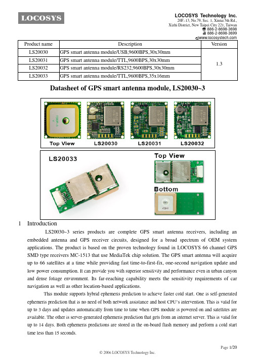
Product name LS20030 LS20031 LS20032 LS20033
SignalTEK 10G 10G Ethernet故障排除和带宽测试仪用户手册说明书

SignalTEK 10G 10G Ethernet Troubleshooter and Bandwidth TesterUser ManualSignalTEK 10GUser ManualGuide d’utilisationBedienungsanleitungGuida utenteManual de usuarioGuia do Usuario用户指南Podręcznik użytkownikaユーザーガイドTREND NETWORKSStokenchurch HouseOxford roadStokenchurchHigh WycombeBuckinghamshireHP14 3SXUnited Kingdom© TREND NETWORKS 2021The information contained in this document is the property of TREND NETWORKS and is supplied without liability for errors and omissions. No part of this document may be reproduced or used except as authorized by contract or other written permission from TREND NETWORKS. The copyright and all restrictions on reproduction and use apply to all media in which this information may be placed. TREND NETWORKS pursues a policy of continual product improvement and reserves the right to alter without notice the specification, design, price or conditions of supply of any product or service. All rights reserved.Les informations dans ce document sont la propriété de TREND NETWORKS et elles sont fournies sans responsabilité pour les erreurs et les omissions. Aucune partie de ce document ne doit être reproduite ou utilisée, sauf en casd’autorisation par contrat ou en cas d’autre autorisation écrite donnée par TREND NETWORKS. Le copyright et toutes les limitations concernant la reproduction et l’utilisation s’appliquent à tous les supports sur lesquels cette information peutêtre placée. TREND NETWORKS améliore continuellement ses produits et se réserve le droit de modifier sans préavis la spécification, la conception, le prix ou les conditions de fourniture d’un produit ou d’un service. Tous droits réservés.Die Informationen in diesem Dokument sind das Eigentum von TREND NETWORKS und werden ohne Gewährleistung der Vollständigkeit oder Korrektheit gegeben. Dieses Dokument darf nur soweit vertraglich oder anderweitig schriftlich von TREND NETWORKS zugesichert ganz oder teilweise vervielfältigt werden. Das Urheberrecht und alle Einschränkungen zur Vervielfältigung und Nutzung gelten für alle Datenträger, auf denen diese Informationen gespeichert werden können. TREND NETWORKS bemüht sich um ständige Produktverbesserungen und behält sich das Recht vor, die Spezifikation, das Design, den Preis oder die Lieferbedingungenjeglicher Produkte oder Dienste ohne Vorankündigung zu ändern. Alle Rechte vorbehalten.Le informazioni contenute nel presente documento sono di proprietà di TREND NETWORKS e sono fornite senza alcuna responsabilità relativa a errori e omissioni. Sono vietati la riproduzione o l’uso di tutto il documento o parte di esso, salvo se autorizzati da contratto o permesso scritto di TREND NETWORKS. Il copyright e tutte le limitazioni sulla riproduzione e l’uso si applicano a tutti i supporti nei quali le presenti informazioni possono essere contenute. TREND NETWORKS segue una politica volta al miglioramento continuo dei prodotti e si riserva il diritto di modificare senza preavviso le specifiche, il disegno, il prezzo o le condizioni di fornitura di qualsivoglia prodotto o servizio. Tutti i diritti riservati.La información que figura en este documento es propiedad de TREND NETWORKS, quien no asume responsabilidad alguna sobre posibles errores u omisiones que puedan existir en este documento. Queda prohibida la reproducción parcial o total de este documento, así como darle un uso distinto al autorizado mediante contrato o autorización escrita por parte de TREND NETWORKS independientemente del formato y soporte de los contenidos. TREND NETWORKS sigue unapolítica de mejora continua del producto y nos reservamos el derecho de modificar sin previo aviso las especificaciones, diseño, precio o condiciones de suministro de cualquier producto o servicio. Todos los derechos reservados.As informações contidas neste documento são de propriedade de TREND NETWORKS e são fornecidas sem responsabilidade sobre erros e omissões. Nenhuma porção deste documento pode ser reproduzida ou usada exceto quando autorizada mediante contrato ou outra permissão por escrito da TREND NETWORKS. Os direitos de cópia e restrições de reprodução e uso são aplicáveis a todas as mídias nas quais estas informações possam ser colocadas. A TREND NETWORKS segue uma política de melhora contínua do produto e se reserva ao direito de alterar sem avisoprévio as especificações, design, preço ou condições de fornecimento de qualquer produto ou serviço. Todos os Direitos Reservados.本文档所包含的信息是美国理想工业公司 (TREND NETWORKS) 的财产,对于本文档中出现的错误或遗漏,提供方概不负责。
Signal Recovery锁相放大器选型指南

11. 最大动态储备> 100 dB
微弱信号检测 — 半个世纪的骄傲
电流输入 1. 输入模式:低噪声(108 V/A) ,宽频带(106 V/A) 2. 满刻度灵敏度:低噪声 2 fA to 10 nA 按 1-2-5 顺序步进 3. 满刻度灵敏度: 宽频带 2 fA to 1 µA 按 1-2-5 顺序步进 4. 输入噪声:低噪声 13 fA/√Hz @ 500 Hz 5. 输入噪声:宽频带 130 fA/√Hz @ 1 kHz 6. 阻抗:低噪声< 2.5 kΩ @ 100 Hz 7. 阻抗:宽频带< 250 Ω @ 1 kHz 8. 增益精度:±2.0% 典型值, 中频
解调器和输出 1. X,Y,R 输出-时间常数 10 us to 640us(二进制序列) 2. X,Y,R 输出-滚降 6dB/octave 3. 所有输出-时间常数 5ms to 100ks 按 1-2-5 顺序步进 4. 所有输出-滚降 6, 12, 18 and 24 dB/octav 5. 绝对相位测量精度 ≤ 0.01°
01065202182电流输入输入模式低噪声和宽带宽满刻度灵敏度低噪声2fa10na按125顺序步进满刻度灵敏度宽带宽2fa按125顺序步进100db噪声低噪声13fahz500hz噪声宽带宽13pahz06typmidband阻抗低噪声25k?100hz阻抗宽带宽250?1khz参考信号通道ttl输入0001hz正弦输入03hz250khz250khz相位设置分辨率0001增量100mstc12dboctaveslope内部参考00001rms100mstc12dboctaveslope外部参考001rms00001解调器和输出输出时间常数10us100ks按125顺序步进所有输出滚降6121824dboctav001振荡器频率0001hz绝对精度50ppm幅度扫描0000v5000vrms仅线性扫描最快50ms步频率扫描0001hz250khz线性和对数扫描最快50ms步振荡器可作为信号源独立使用其他数据缓存32k点存储adc以及锁相放大器输出数据能将数据绘成图形
来自台湾的多卫星定位科技POWERTECH DG-240 DiSEqC Motor极轴座

来自台湾的多卫星定位科技POWERTECH DG-240 DiSEqC
Motor极轴座
娄军
【期刊名称】《卫星电视与宽带多媒体》
【年(卷),期】2007(000)013
【摘要】@@ 小小的极轴座确实带给我们不少方便,特别是在接收大跨度、多卫星方面上.但是我们有时也要为它"不良举动"付出一些辛劳:马达转动时的声音过大而遭到邻居的投诉;一些不知名的原因搞它的不听使唤,一边边爬上屋顶来检查、一边边将它拆下去送修.你或许和我一样曾无数次的自问过:马达到底是带给我们的方便还是麻烦.台湾POWERTECH DG-240极轴座也许可以提供给我们一些答案.
【总页数】2页(P65-66)
【作者】娄军
【作者单位】无
【正文语种】中文
【相关文献】
1.来自台湾的CNC教练机之父——记台湾仁安信息科技总经理陈清安 [J], 马宁
2.论极轴天线座单轴转动天线选同步卫星中的精度问题 [J], 韩树刚
3.一款具有自动定位系统功能的Ku极轴座--SuperJackDG-120+ [J], 娄军
4.商丘市两座北斗卫星导航定位基准站通过验收 [J], 侯良川
5.台湾将用“金牛座”发卫星 [J],
因版权原因,仅展示原文概要,查看原文内容请购买。
- 1、下载文档前请自行甄别文档内容的完整性,平台不提供额外的编辑、内容补充、找答案等附加服务。
- 2、"仅部分预览"的文档,不可在线预览部分如存在完整性等问题,可反馈申请退款(可完整预览的文档不适用该条件!)。
- 3、如文档侵犯您的权益,请联系客服反馈,我们会尽快为您处理(人工客服工作时间:9:00-18:30)。
TOPSIGNAL TP8801 DiSEqC 1.0/1.2协议极轴天线控制器的应用一二原理简介通常C波段电动极轴天线和传统KU极轴天线组成使用的条件是极轴天线、天线控制器、电动推杆。
根据极轴天线面大小匹配对应功率的天线控制器和相应尺寸的电动推杆(常用12、18、24寸推杆,ku极轴天线使用推杆相对较小)。
就c波段极轴天馈系统而言,想要让天线效率得到充分发挥,最好的办法就是将正馈天线的ku高频头设为主焦,C波段高频头设为副焦;再通过DiSEqC 1.0切换器或者22k开关对2路卫星信号进行切换使用,这是极轴前辈曾文明老师提出的。
而传统支持DiSEqC1.0协议的天控器和卫星接收机只能单独使用。
即打算从1个卫星节目转换到另1个卫星节目,需要先遥控天控器去驱动电动推杆,继而在极轴天线定位后再把卫星接收机遥控切换到相应卫星的频道上,需要操作2个遥控器才能去达成目的。
设备特点TOPSIGNALTP8801型天控器除了可以推动普通KU天线外,还可以驱动3-5米直径的极轴天线(需更换相应驱动单元);并能够存储多达99颗卫星位置。
此外其最大的特点还有兼容普通卫星接收机使用的DiSEqC1.0协议,在没有DiSEqC 1.2协议卫星接收机的情况下也可以单独正常使用。
而我所看中的正是其支持DiSEqC 1.2协议的功能。
这样就可以通过支持DiSEqC 1.2协议的卫星接收机(如DM500S、430)进行跨星换台操作,该天控器会自动驱动极轴天线寻星定位后进行播放。
这一先进的技术以前只在ku天线相关极轴产品上采用,如SVEC 9120、DG240等水平极轴座之类,而C波段极轴天线产品上鲜有使用。
从接口来看,TP8801与普通DiSEqC 1.0天控器略有不同。
前者增加了1进1出的75-5的F信号端子,如果只使用DiSEqC 1.0协议功能时,只需把天控器的电源和推杆的4根相应控制线进行连接即可,即电源正负M1 M2 传感器sensor GND。
当使用DiSEqC1.2协议功能时,除了接好这4根控制线,还需要把卫星天线的F线接入天控器后,再输出到带有DiSEqC1.2协议的卫星接收机上。
调整天控器由于笔者的3米SVEC C波段网状极轴天线室外单元以前已经基本调试到位(只是KU波段主焦初调完成,C波段副焦信号尚可)。
所以在使用TOPSIGNALTP8801天控器时只需在室内把原来的DiSEqC 1.0天线控制器线路进行连接更换即可。
原极轴天线24寸推杆内已设置好东西边界的硬件凸轮物理行程限位,此次无须再进行调整。
否则需要对推杆设置清零,再对天控器进行极轴天线的软件东西限位设定,或者在使用DM500S接收机时,通过极轴菜单设置对软件东西边界的设定进行操作。
首次使用该极轴天线控制器时,笔者建议各位最好用原来的天控器把极轴天线调动到正南方向再更换新天控器,此举目的是配合新天控器天线进行零点设置。
启用新天线控制器时,开机会显示000的状态,这时再向左或者向右调节TP8801时,机身上的绿色数码指示灯就会有脉冲计数指示。
笔者的极轴天线正常使用时以正南为0点,极轴天线面左右接近1个平面。
向左偏向时天线推杆向内拉动,极轴天线偏向东方,天控器的脉冲数字从0开始依次向上叠加。
当极轴天线向右偏向时天线推杆向外推出,极轴天线偏向西方,天控器脉冲数字从999开始依次向下跌减。
所以说,把极轴天线调整到正南方位再接入TP8801天控器是很有必要的,这样可以直观从天控器数据的变化中显示出极轴天线究竟是偏向东边或者西边。
对于使用普通DiSEqC 1.0协议接收机的朋友,笔者建议你们在开始使用TP8801天控器时首先将其清零后再设定软件东西边界极限限位。
因为这类接收机无法在接收机设置中对天控器进行设置,只能通过天控器的遥控器进行相应操作。
大家都知道DiSEqC 1.0协议最少支持4个卫星信号的输入和切换。
实际上如果只有1个高频头时也就无需对接收机端口进行设置了,剩下的工作就只是对天控器进行设置操作。
接下来,我们可以使用遥控器进行极轴天线及天控器的软件边界设定。
先按控制面板上的“E/W”、“W/E”键或者遥控器上的左/右转动键驱动推杆至最低(极轴天线东面)或最高(极轴天线西面)位置,在遇到极轴天线推杆硬件物理限位后,天控器会显示“”。
此时向相反方向调节即可进行下一步操作。
再按遥控器上的“Limit”键,数码管显示“L--”。
再按遥控器上的右键,数码管显示“L.L.”并闪烁。
然后再按ENTER键3秒确认设置左边界,此时数码管显示“L.L.”不再闪烁。
表示已经设定好左(东)边软件极限。
驱动极轴天线向西边到达物理限位后再返回部分后按遥控器上的“Limit”键,数码管显示“L--”。
再按遥控器上的左键,数码管显示“H.L.”并闪烁。
然后再按ENTER键3秒,确认设置好右(西)边界,此时数码管显示“H.L.”不再闪烁。
如此设置后,无论如何向东或向西驱动极轴天线操作都会在推杆物理限位前提示已经到达相应的边界“.”或者“”,不会显示出“”。
下一步是将接收机的设置根据实际情况进行调整,比如笔者的四切1开关2输入为5150MHZ C 波段,3输入为9750/10600MHZ KU波段。
所以把105.5E的凤凰卫视参数输入到接收机后,向左(东边)驱动极轴天线找寻信号。
由于室外极轴天线轨迹已经完全调整正确,很快就会出现凤凰卫视的信号质量,找到信号质量最大值后可以按遥控器“store”键,此时数码管显示“C- -”。
输入自定义的星位如01,再按“ERTER”键3秒后看到数码管的“C01” 变成“P01”,表示存星过程完成。
存完参数之后,就可以搜索卫星节目了。
也可以在查看最低信号质量节目后,微调极轴天线,再次保存卫星位置。
此后继续向东找寻108E、115E、122E、134E等卫星,向西找寻100.5E、95E、88E等卫星位置。
笔者的极轴天线向东可收下卫星最大角度为166E,向西最大角度为68.5E。
此前安装调试时,由于笔者对24寸推杆承受力量不甚了解,又缺乏调试经验,以至于极轴天线安装位置错误,造成推杆负重过载而损坏。
极轴天线负载最重的地方就是东西边界特别是166E和49E。
当24寸推杆从166E拉动3米网状极轴天线时,天线偏地面方向,承受力量非常大,驱动电流同时也远超正常范围。
如果推杆质量不好,很容易会拉坏螺丝口报废。
最后笔者根据实际使用情况确定了极轴天线推杆的正确安装位置,而驱动推杆的电流也在正常使用范围,不会出现24寸推杆在极轴天线右边安装时拉动极轴天线那样超载的巨大力量和过载结果。
此时天控器驱动3米天线最大负载从166E改变为68.5E,天线偏向角度减小,也减小了推杆所承受的拉力(我放弃49E以增加极轴天线安全区);如果不这样调整唯一的办法就只有将24寸推杆更换为36寸推杆了。
调换星过程如下:通过遥控器上下键进行选星,在已选星位号出现约3秒后,数码管显示脉冲数字自动驱动推杆到存星位置。
该功能为TP8801系列特有功能,无须2次确认。
此换星操作最少需要存入2星位置后才有效。
也可直接输入数字星位号如08,数码管显示“P08”,然后再按ENTER确认,推杆会走到存星位置,在原位置输入相同星位则不会动作。
使用普通支持DiSEqC 1.0协议接收机配合该天控器极轴天线使用时,换星换台必须使用到2个遥控器,可以先用天控器的遥控器选换好卫星位置再切换接收机卫星信号,也可以先切换好卫星频道后再换星,2者缺一不可。
天控器与DM500的配合目前常用的430xp和DM500S接收机均可支持DiSEqC 1.2极轴协议,配合天控器最为方便,其中DM500S不仅支持 DiSEqC 1.0、1.1、1.2协议,而且也是当前最流行的机器。
下面笔者就简述一下通过DM500S设置该天控器的过程。
1、存储卫星数据首先利用原极轴天线天控器把极轴天线驱动到正南中心位置,再把TOPSIGNALTP8801 天控器接入系统。
此时可能出现有两种情况:一是天控器已经存好预收卫星数据时,可以用天控器调星,依次找到所有卫星的数据存入天控器,二次使用时则由DM500S控制天控器自动调星。
相当于把天控器内数据copy到DM500S接收机。
二是把TP8801 天控器初始化清零,使用DM500S直接在极轴设置中驱动极轴天线寻找卫星信号,并保存卫星位置和下载节目,这个过程相对于前一种方式更复杂一些,全部卫星位置设置过程所需时间更长。
原因很简单,DM500S(在使用四切一时)反应没有普通免费机灵敏,找星时会有所延迟,以至于天控器在驱动推杆跑过欲收卫星位置时,还没有及时反应而延长调试时间。
特别是信号较弱的卫星在这个问题上更为突出,需要更长时间才可以搞定。
实际上无论哪种方式去寻找卫星信号和存储卫星位置,都必须使用DM500S的极轴设置功能。
2、调整极轴设置在首次使用DM500S的 DiSEqC 1.2协议极轴功能之前,要对高频头进行设置,方可启动极轴功能。
虽然DM500S接收机有现成的极轴定义下的所有卫星,但是每次设置都很繁琐,不利于实际操作,所以笔者在《非标准用户定义设置》菜单中增加新卫星进行极轴设置。
在笔者的极轴天线上,所有C波段卫星统一使用1个5150MHZ本振高频头设置,所有KU波段卫星统一使用1个9750、10600MHZ双本振高频头设置。
注意在天控器高频头设置时不能选择增加电压,否则会出现无法正常工作的状况。
DISEqC参数根据个人4切1输入情况选择,在DISEqC模式中启用Version 1.2极轴功能,在频道搜索中的第3项“极轴设置”功能菜单内就会有相应的极轴关联选项了。
(见图6-7)由于笔者在LNB选项中配置了2个高频头,所以进入极轴设置时,系统会要求选择其中1个高频头(如图8)。
进入极轴设置选项后可以在使用GOTOXX功能下输入当地经纬度保存(如图9),再在极轴配置下的“模式”菜单选择“位置”,并选择卫星。
转发器任意选择一组参数(如图10),极轴天线的方向则依据DM500S遥控器的左右键而改变,若出现控制方向与极轴天线实际动作不一致时,需要把推杆电源正负极调换,相关物理极限也需要调整。
当预收卫星信号SNR AGC数值最高,BER最小的情况下,可以用DM500S对该卫星位置进行存储,天控器也会作出对应的数据显示。
由于DM500S只支持存储79个星位,而天控器最高可存储99个。
所以打算用DM500S去驱动极轴天线的用户必须在79内选择存储星位(如图11)。
保存卫星位置后,可以在多星选择中找出刚才存下的卫星,选择自动搜索该卫星信号即可。
写在最后使用TOPSIGNALTP8801 DiSEqC 1.0、1.2协议天控器配合SVEC 3M网状极轴天线1年多来,笔者对其功能颇为满意,它唯一的缺点就是遥控器按键之间的距离太近,按键体积太小,在使用时容易发生误操作,建议厂商在后续产品中予以改进。