WYD-804说明书
无线温控器使用说明书(带遥控器)分析

无线温控器使用说明书一、技术参数1、电源:控制器:DC 6V、遥控器:5号电池两节2、功耗:<0.5W3、环境温度:0----70℃4、显示温度:0----40℃5、控制温度:10----26℃6、控制精度:±1℃,温度分辨率:0.1℃7、尺寸:8、重量: 180g二、主要功能1、无线温控器由SHW301遥控器和SHW302控制器组成,SHW301遥控器完成对室温的采集、与控制器的数据传输、参数显示、参数设置等功能;SHW302控制器完成对阀门的开关控制、热量管理、RS485数据通信、对遥控器无线通讯等功能。
2、无线温控器具有两种收费方式,一种是不需要充值就可以使用,计算“已用时间”收费,液晶面板不显示“调试”;另一种是通过充值后温控器工作,遥控器液晶面板“调试”出现闪动,出厂默认“剩余时间”设置为“0000小时00分钟”,余额为64小时温控器报警提示充值;倒计时累计为“0000小时00分”后,阀门自动关闭。
3、根据设定室温和当前室温控制供热阀门通断,当室内温度低于设定室温1℃时,打开阀门加热;当室内温度高于设定室温1℃时,关闭阀门。
使室内尽量保持恒温,从而实现节能目的。
4、“设定室温”默认值范围为“10℃---36℃”,可通过远程命令修改“设定室温”值上限及下限范围。
5、阀门关闭期间余额不减,节能的同时节省费用。
6、断市电后,SHW302控制器由电池供电,当电池电量降低到一定程度,控制器自动打开阀门,保证了在断电情况下,能够正常供暖。
7、温控器能够实时监测阀门是否连接正常、阀门开关是否到位,并可将检测状态上报。
8、设置专有节能按键,用户外出时使用此键,即维护了建筑温度,又节约了能源。
9、为了防止在不供暖期间阀芯生锈、结垢造成阀门堵转,在温控器供电正常情况下,每隔12天左右阀门自动开关一次。
10、支持RS485通信功能,远程读取面板显示信息,包括当前室温、设定室温、剩余时间、已用时间、阀门开关信号、温控器运行模式等信息,可对设定室温、最高设定室温、温度修正值、剩余时间、计费模式实施远程修改,还可以对阀门开关、温控器开关、工作模式切换进行远程控制。
维金Lite方向控制阀门值,G1 8,G1 4和G3 8说明书

3
Strategic Rationale
• To penetrate the global in-line valve market
• $100m addressable market
• Highly competitive product to address the in-line valve market in all regions of the world
• Overview • Specification • Design features • Options & accessories • Viking Lite & Xtreme – product differences
• Price & product positioning • Launch date • Summary
Viking Lite
Directional Control Valves
G1/8, G1/4 & G3/8 Body Ported
08 November 2019
Viking Lite
Table of contents
• Strategic rationale • Product information
Accessories
• Manifold bar - Anodised aluminium • Pressure bar - Anodised aluminium
10
Viking Lite
Table of contents
• Strategic rationale • Product information
AtlasIED DPA804多通道网络放大器说明书

S o u n d L P . T h e A t l a s “C i r c l e A ”, S o u n d o l i e r , a n d A t l a s S o u n d a r e t r a d e m a r k s o f A t l a s S o u n d L .P . I E D i s a R e g i s t e r e d T r a d e m a r k o f I n n o v a t i v e E l e c t r o n i c D e s i g n s L L C . A l l r i g h t s r e s e r v e d . d e m a r k s a r e p r o p e r t y o f t h e i r r e s p e c t i v e o w n e r s . N o e n d o r s e m e n t i s i m p l i e d . D u e t o c o n t i n u a l p r o d u c t d e v e l o p m e n t , s p e c i f i c a t i o n s a r e s u b j e c t t o c h a n g e w i t h o u t n o t i c e . A T S 005591 R e v A 3/17DPA804Multi-Channel Network AmplifierFeatures• Configurations• 4 x 200 Watt 70V (Factory Default) • 4 x 200 Watt 100V • 4 x 150 Watt 8Ω • 4 x 100 Watt 4Ω• 2 x 200 Watt 70V / 100V & 2 x 150 Watt @ 8Ω • 2 x 200 Watt 70V / 100V & 2 x 100 Watt @ 4Ω• No Computer Required to Operate • Networkable• Configurable DSP via GUI• Convection Cooled / Fan Assist• PC Based DPA Site Manager Software with LAN IP Auto-Discovery, Fault Reporting, Input & Output Status, Standby Status and Amplifier Remote Activation via a Scheduler Timer• On-Board Web Browser GUI for Remote Monitoring of Status & Levels • User Page with Assignable Level Control, Post Contractor Settings, Password Protection• Mute Assignments Triggered via Audio Signal or Contact Closure • Audio Sense Auto Power Down (APD)• DSP Parameters per Output, Parametric EQ, Hi & Lo Cut Filters, Delay, Limiter• Four (4) Balanced Inputs, Expandable to Eight (8) via Accessory Card • Optional Accessory Card Slot for a DPA-DAC4 Four-Channel Dante™ Receiver or a DPA-AMIX (2) Mic / Line, (2) AUX Input Card • PC, iOS ®, & Android ® Controllable• Assignable Level Controls, Onboard GUI (Security Password Protected) or by Front Panel Pots with Tamper Deterring Covers• Four (4) GPIO Control Ports Assignable in GUI for Mute or Remote LevelApplicationsThe flexible DSP , remote web monitoring, and control of the DPA Series amplifiers makes them the perfect choice for presentation rooms,classrooms, conference rooms, and retail background / foreground music applications.General DescriptionThe AtlasIED DPA Series amplifiers feature a combination of flexibility, performance, and control to provide high value features for applications that require more than just great sound. The network enabled DPA series amplifiers are DSP controlled four-channel amplifiers that can be configured in three different amplification arrangements to meet a wide range of installation design requirements.DPA amplifiers can be used right out of the box in their factory default configuration as traditional four-channel 70.7V commercial power amplifiers requiring no programming, special set-up, or networkconnectivity. However, when web enabled, the DPA amplifiers can be configured in four-channel mode with either 4Ω or 8Ω load impedances for two stereo zones. Many system designs require both low and high impedance amplification. The DPA series can be configured for a 70.7V/100V paging/background system on two channels and the other two channels can be used for 4Ω/8Ω foreground stereo applications.The DPA comes standard with four balanced line inputs and anaccessory slot for an optional DPA-DAC4 four-channel Dante™ receiver card or a DPA-AMIX (2) mic/line and (2) AUX input card, for a total of eight inputs. All inputs can be mixed and routed to any of the four amplifier channels. All amplifier channels have an assortment of DSP tools including level controls, EQs, limiters, high & low pass filters, and delay to provide flexibility for a range of applications.The output level can be assigned to either the front panelpotentiometers or to the onboard GUI. Wired remote level controls can be configured to allow simple control for the end user. Each unit also features GUI based input and output level metering along with assignable mute functions that are triggered via an audio signalor contact closure. Access to the DSP settings is accomplished viacomputer, tablet, or mobile device using a web browser. All settings can be password protected.The DPA series amplifiers also include PC based site manager software that automatically searches within a specific network for all DPAamplifiers on the network. It will list them and allow single click access to any unit. The DPA Site Manager software can do a variety of functions besides locating IP addresses such as; fault reporting, input & output status, standby status and remote activation via a scheduler timer.The flexibility of the DPA Series amplifiers and comprehensiveassortment of local or network control configurations make them an ideal choice in today's sophisticated commercial audio market.DPA804 FrontDPA804 BackS o u n d L P . T h e A t l a s “C i r c l e A ”, S o u n d o l i e r , a n d A t l a s S o u n d a r e t r a d e m a r k s o f A t l a s S o u n d L .P . I E D i s a R e g i s t e r e d T r a d e m a r k o f I n n o v a t i v e E l e c t r o n i c D e s i g n s L L C . A l l r i g h t s r e s e r v e d . d e m a r k s a r e p r o p e r t y o f t h e i r r e s p e c t i v e o w n e r s . N o e n d o r s e m e n t i s i m p l i e d . D u e t o c o n t i n u a l p r o d u c t d e v e l o p m e n t , s p e c i f i c a t i o n s a r e s u b j e c t t o c h a n g e w i t h o u t n o t i c e . A T S 005591 R e v A 3/17S o u n d L P . T h e A t l a s “C i r c l e A ”, S o u n d o l i e r , a n d A t l a s S o u n d a r e t r a d e m a r k s o f A t l a s S o u n d L .P . I E D i s a R e g i s t e r e d T r a d e m a r k o f I n n o v a t i v e E l e c t r o n i c D e s i g n s L L C . A l l r i g h t s r e s e r v e d . d e m a r k s a r e p r o p e r t y o f t h e i r r e s p e c t i v e o w n e r s . N o e n d o r s e m e n t i s i m p l i e d . D u e t o c o n t i n u a l p r o d u c t d e v e l o p m e n t , s p e c i f i c a t i o n s a r e s u b j e c t t o c h a n g e w i t h o u t n o t i c e . A T S 005591 R e v A 3/17S o u n d L P . T h e A t l a s “C i r c l e A ”, S o u n d o l i e r , a n d A t l a s S o u n d a r e t r a d e m a r k s o f A t l a s S o u n d L .P . I E D i s a R e g i s t e r e d T r a d e m a r k o f I n n o v a t i v e E l e c t r o n i c D e s i g n s L L C . A l l r i g h t s r e s e r v e d . d e m a r k s a r e p r o p e r t y o f t h e i r r e s p e c t i v e o w n e r s . N o e n d o r s e m e n t i s i m p l i e d . D u e t o c o n t i n u a l p r o d u c t d e v e l o p m e n t , s p e c i f i c a t i o n s a r e s u b j e c t t o c h a n g e w i t h o u t n o t i c e . A T S 005591 R e v A 3/17NOTES:1. P ower level measurment is define as follows: 1Hz Sine wave signal burst of 20 cycles (20mS) at 1% THD+N, followed by 480 cycles of a 1kHz sine wave at 10% of the max power. Other power measurements are available upon requests.2. P ower measurement with Ethernet connected. Without Ethernet connected deduct .2W3. A verage Power is defined as Pink Noise input signal applied to achieve 1/4 of the 4 Ohm or 70.7V power rating.4. Max Power is defined as 1 KHz input signal applied to achieve the maxium power output before clipping into a 4 Ohm or 70.7V load.5. BTU is calcualed by the AC Mains Power consumed minus the total power output measured at the specified load and condition, multiplied by 3.412. Example: 785 Watts from the AC Source - 600 Watts Total Output power = 185 x 3.412 = 631 BTUS o u n d L P . T h e A t l a s “C i r c l e A ”, SR e g i s t e r e d T r a d e m a r k o f I n n o v a t i v e E l s L L C . A l l r i g h t s r e s e r v e d . d e m a r k s a r e p r o p e r t y o f t h e i r r e s t d e v e l o p m e n t , s p e c i f i c a t i o n s a r e s u b j e i t h o u t n o t i c e . A T S 005591 R e v A 3/17Dimensional Drawings14.515.5S o u n d L P . T h e A t l a s “C i r c l e A ”, S o u n d o l i e r , a n d A t l a s S o u n d a r e t r a d e m a r k s o f A t l a s S o u n d L .P . I E D i s a R e g i s t e r e d T r a d e m a r k o f I n n o v a t i v e E l e c t r o n i c D e s i g n s L L C . A l l r i g h t s r e s e r v e d . d e m a r k s a r e p r o p e r t y o f t h e i r r e s p e c t i v e o w n e r s . N o e n d o r s e m e n t i s i m p l i e d . D u e t o c o n t i n u a l p r o d u c t d e v e l o p m e n t , s p e c i f i c a t i o n s a r e s u b j e c t t o c h a n g e w i t h o u t n o t i c e . A T S 005591R e v A 3/17S o u n d L P . T h e A t l a s “C i r c l e A ”, S o u n d o l i e r , a n d A t l a s S o u n d a r e t r a d e m a r k s o f A t l a s S o u n d L .P . I E D i s a R e g i s t e r e d T r a d e m a r k o f I n n o v a t i v e E l e c t r o n i c D e s i g n s L L C . A l l r i g h t s r e s e r v e d . d e m a r k s a r e p r o p e r t y o f t h e i r r e s p e c t i v e o w n e r s . N o e n d o r s e m e n t i s i m p l i e d . D u e t o c o n t i n u a l p r o d u c t d e v e l o p m e n t , s p e c i f i c a t i o n s a r e s u b j e c t t o c h a n g e w i t h o u t n o t i c e . A T S 005591 R e v A 3/17Architect and Engineer SpecificationsThe power amplifier shall be a four-channel switch mode power amplifier with efficient BASH Hybrid topology output circuitry. The amplifier shall be configurable as four-channel high impedance 70V/100V or four-channel low impedance 4Ω or 8Ω or two-channel low impedance 4Ω or 8Ω and two-channel high impedance 70V/100V mode. The amplifier shall be shipped factory preset in four-channel 70V configuration. The I/O router shall be configured as follows: Input 1 routed to Outputs 1, Input 2 to Output 2, Input 3 to Output 3 and Input 4 to Output 4. This out of box configuration will not require a computer or network to operate.The performance specifications shall match or exceed the following: 70V / 100V = 4CH x 200W; 8Ω = 4CH x 150W, 4Ω = 4CH x 100W; 70V / 100V = 2CH x 200W & 8Ω = 2 CH x 150W;70V / 100V = 2CH x 200W & 4Ω = 4CH x 100W; (referencespecifications Notes 1-4); Input Sensitivity 750mV Balanced, 0dBU; Input Impedance Balanced 40K Ohms; Max Input Level channels 1-4, +14dBU, 7dBU inputs 5-8 with Dante™; THD 1% at rated output, .2% Typical; Frequency Response -3dB 20Hz @ 20kHz (DSP set to flat);Signal to Noise Ratio -100dB Below Rated Output A Weighted; Crosstalk >70dB @1kHz; Protection circuits =Thermal, Short, Signal Limiter; Sleep Mode (Ethernet Active) 3.5W, 12BTU; Standby/ADP mode 14W, 48BTU; Max Power All CH driven 70.7V/100V (default mode) = 704W, 390BTU. Dimensions: 1 x RU, 19" W x 1.72" H x 15.5" D. Weight 13.1 lbs.The power amplifier shall have a front panel power switch and three states of idle power: Idle Active Mode, Sleep Mode, and Standby Auto Power Down (APD) Mode. Each mode shall have an LED indicator on the front panel indicating the power status. When in Sleep Mode, the Ethernet shall remain active for access to the amplifiers on board GUI. The amplifier shall include convection cooling with dynamic fan assist for extreme conditions. If the unit is not being used or in Standby mode, the fan shall not be needed for cooling and shall remain Off until the unit is in heavy use. As heat is generated in the amplifier during use, the fan shall activate at a low speed and increase as needed to maintain the amplifier at safe operating temperature. The amplifiers air flow shall be from rear to front.The front panel controls shall consist of four volume controls that can be removed and replaced with included security covers. Above each volume control, LED indicators for Signal and Limit/Protect/Mute shall signal the amplifier output operating condition. The four-channel output operating mode shall be displayed to the right of the output indicators by 4multicolor LEDs. These indicators illustrate if Channels 1 and 2 and 3 and 4 are low impedance 4Ω or 8Ω or 70V/100V output. Amplifier operation mode settings shall be completed using the internal DSP GUI.On the rear panel, the amplifier shall have an IEC AC receptacle that operates from 110V - 120V & 220V - 240V and shall automatically sense the AC Mains voltage and change voltage settings. A removable AC Mains fuse shall be provided for protection.The rear-mounted Input connectors for inputs 1 - 4 shall be individually removable 3-way 3.5mm Phoenix type connectors that accept balanced line input signals (+) (–) and (GND) pins and will support unbalanced signals by connecting the (–) and (GND) pins together. The amplifier configuration and I/O Routing shall be done in the GUI. Any Input shall be capable of being routed to any Output.The rear-mounted Output connector shall be a screw terminal block type for connecting speakers to the amplifier. The recommended wire to use shall be Class 3 rated,14-gauge wire or lower for speaker wiring. Amplifier output channel configurations shall be done in the amplifier GUI. The amplifier shall be shipped with two speaker output terminal covers for safety. Included in the carton with the amplifier shall be eight (8) spade crimp terminals that accept 12-gauge wire and four (4)security cover screws (M3 x 8mm). Terminal block screws shall be M4. The amplifier shall be pre-configured at the factory for four-channel 70.7V/100V mode.The amplifier shall have one (1) rear mounted Accessory Card Slot to add accessory modules. Accessory modules shall make available 4 additional inputs (for a total of 8) that can be routed to any of the four outputchannels. Optional accessory cards shall include a four-channel Dante™ Digital Audio Input Card and a four-channel Analog Mic/Line, Auxiliary Input Card.The amplifier shall have a rear-mounted Ethernet connector to connect to a Local Area Network (LAN), computer, or router/switch using a standard RJ45 cable to access the amplifiers DSP and control settings.When network enabled, the amplifier shall have a GUI home page with Input and Output active meters, Output Configuration indicators, with Tab selections to navigate to User PC Control page, Amplifier Setup page, Mobil Control page, IP Configuration page where I/O can be labeled, Update page for firmware upload, and About page. All fouramplifier channels shall have an assortment of DSP tools with navigation icons to the following individual GUI pages: Amplifier Configuration, Mute, Link & Ports Assign, I/O Router Assign, Hi & Lo Pass Filters, 5-Band Parametric EQ, Output Level, Delay, and Limiter.The amplifier shall have four (4) rear-mounted Control Ports to allow assigned/configured Remote Level or Mute functions to be activated by external contact closure relay or controlled by voltage. Each Control Port pin shall be assigned to one function such as Mute or Level, but not both. Control Port assignment shall be done in the GUI Mute, Link, Port Assignment Page. The factory default assignments for the Amplifier Control Ports are assign as a Remote Level & shall be as follows: C1 controls Output 1, C2 controls Output 2, C3 = controls Output 3, C4 controls Output 4. The Control Ports shall provide +10V and GND connections for Remote Level Control Port using 10k Ω Linear Taper pots. The amplifier shall have Site Manager software to perform a variety of functions including locating DPA amplifiers' IP addresses; fault reporting, input & output status, standby status, and remote activation via a scheduler timer.The amplifier shall be an AtlasIED DPA804.。
WYD-800微机远动装置使用说明书

面上鼠标右键点击网上邻居选择属性,弹出“网络和拨号连接”窗口。
图4-2 IP指定窗件中的所需IP图4-3 “站内参数”设置窗口,(接,(接状态,(接,(图5-1 RTU监测与配置主界面置设置工具栏中的“站内设置”,输入正确的密码后进入站内参数设置窗口,如图5-2图5-2 站内参数设置窗口图5-3 双机切换串口参数配置窗口指两次切换的最小时间间隔,在这个图5-4 通道参数配置窗口“参数配置”的窗口中,根据工具栏中当前通道选择下拉菜单选择所要配置通道。
修改参数,‘系统编号’可以修改,推荐保证每个间隔的相同库内的系统编号不能重复。
在通道内的数据参数与装置设置(生成数据库)中的数据参数完全相同,但系统编号是自动新建装置时,新建的系统编号是从前一次生成的数据库内的最大系统编号加2开始安排有一些技术参数指标要求,即:模拟量库、开关量库、SOE库、遥控库和脉冲库的最大系统查看网关属性新建网关:点击“新建网关”即可弹出新建网关的窗口,如图5-5所示:图5-5 新建网关窗口网关名称:是在通道参数配置窗口中左边看到的树状内显示的网关名称,一个间隔即一个网关对IP。
网关编号:是代表这个间隔的唯一标识,不能重复,且在0~255之间取值包括0和255,“确定”按钮,稍等片刻即可生成新的数据库。
图5-7 添加间隔窗口下面举例具体说明,假设该821线路网关支持双网,装置地址分别为18、19,分别为““南京路”线路保护,网关IP为“10.100.100.12”和“11.100.100.12”,则操作过程如下:1、选择“双网”(这里以双网配置为例);扇区”按钮,弹出窗口如图5-9所示:图5-10 增加扇区窗口加模板”操作,选中所要添加的扇区,点击“增加”按钮,再添加公共地址中的,按置中的下点击按钮,图5-11 通道设置向导窗口置串口和以太网两种通讯类型。
例如选择串口类型,点击“图5-12串口规约选择窗口SC1801、U4F、DNP、IEC101、DISA、GPS、VANCOMM 图5-13 串口参数设置窗口图5-14高级配置窗口图5-16 CDT规约高级设置窗口送报文中的目的站号,即主站的地址编号。
EPD804Z-S4G2系列多功能网络仪表使用说明书

网络多功能电力仪表(LED版)使用手册(2012.05.V2.0版)目录一、概述 (1)二、技术参数 (1)2.1辅助电源 (2)2.2输入信号 (2)三、编程和使用 (2)3.1按键定义 (2)3.2测量显示…………………………………………………………………2-33.3 页面显示示意图……………………………………………………………………3-73.4编程操作 (8)3.5菜单组织结构图 (9)3.6编程菜单结构图 (10)调试举例图…………………………………………………………………………11-14四、数字通讯 (15)4.1 报文格式指令………………………………………………………………16-194.2脉冲输出 (20)4 .3 开关量输入 (20)4 .4开关量输出 (21)开关量输出对照表 (22)4. 5变送输出 (23)变送输出对照表……………………………………………………………………24-25 M O D B U S-R T U通讯地址信息表………………………………………………26-31五、接线图 (32)42 方型接线图 (32)96方型接线图 (33)80方型接线图 (34)六、常见问题及解决方案 (35)网络多功能电力仪表--用户手册一、概述网络多功能电力仪表是一种具有可编程测量、显示、数字通讯和电能脉冲变送输出等功能的网络多功能电力仪表,能够完成电量测量、电能计量、数据显示、采集及传输,可广泛应用变电站自动化,配电自动化、智能建筑、企业内部的电能测量、管理、考核。
测量精度2.1 辅助电源:网络多功能电力仪表具备通用的(AC/DC)电源输入接口,若不作特殊声明,提供的是AC/DC85~270V电源接口的标准产品,请保证所提供的电源适用于该系列的产品,以防止损坏产品。
注:采用交流供电时,建议在火线一侧安装1A保险丝。
电力品质较差时,建议在电源回路安装浪涌抑制器防止雷击,以及快速脉冲群抑制器。
Philips 55OLED804 65OLED804 用户手册说明书

Register your product and get support at OLED804 series /TVsupport用户手册55OLED80465OLED804内容1 新增功能 41.1 主页和频道41.2 应用程序和飞利浦电视系列42 设置 52.1 阅读安全说明52.2 电视支架和壁挂安装52.3 摆放提示52.4 电源线52.5 天线52.6 圆盘式卫星天线63 遥控器 83.1 键概述83.2 将遥控器与电视配对103.3 语音搜索103.4 键盘103.5 红外传感器113.6 电池113.7 清洁114 打开和关闭 124.1 开机或待机124.2 电视上的按键125 频道 135.1 安装频道135.2 频道列表135.3 频道列表排序135.4 观看频道135.5 收藏频道165.6 文本/图文电视175.7 互动电视186 频道安装 196.1 卫星安装196.2 天线安装216.3 频道列表复制237 连接设备 257.1 关于连接257.2 带智能卡的 CAM - CI+25 7.3 家庭影院系统 - HTS267.4 智能手机和平板电脑277.5 蓝光光盘播放机277.6 DVD 播放机277.7 蓝牙277.8 耳机287.9 游戏控制台287.10 USB 硬盘驱动器287.11 USB 键盘297.12 USB 闪存盘297.13 照相机307.14 摄像机307.15 电脑308 连接 Android TV 318.1 网络和互联网318.2 Google 帐户328.3 主屏幕338.4 飞利浦电视系列应用程序339 应用程序 359.1 关于应用程序359.2 Google Play359.3 启动或停止应用程序369.4 锁定应用程序369.5 管理应用程序379.6 存储3710 互联网 3810.1 启动互联网3810.2 互联网选项3811 快捷菜单 3912 来源 4012.1 切换设备4012.2 电视输入的选项4012.3 设备名称和类型4012.4 重新扫描连接4013 网络 4113.1 网络4113.2 蓝牙4114 设置 4214.1 图片4214.2 声音4514.3 流光溢彩设置4614.4 环保设置4814.5 一般设置4814.6 时钟、区域和语言设置50 14.7 Android 设置5114.8 通用接入设置5114.9 锁定设置5115 视频、照片和音乐 52 15.1 来自电脑或 NAS5215.2 收藏夹菜单5215.3 最流行菜单和最后播放菜单52 15.4 来自 USB 连接5215.5 播放视频5215.6 查看照片5315.7 播放音乐5416 电视指南 5616.1 您需要执行的操作5616.2 电视指南数据5616.3 使用电视指南5617 录制和暂停电视 5817.1 录制5817.2 暂停电视5918 智能手机和平板电脑 61 18.1 飞利浦电视遥控应用程序61 18.2 Google Cast6118.3 AirPlay6119 游戏 6219.1 您需要执行的操作62 19.2 游戏手柄6219.3 玩游戏6220 流光溢彩 6320.1 流光溢彩风格6320.2 关闭流光溢彩6320.3 流光溢彩设置6320.4 Lounge Light 模式6321 精品选择 6521.1 关于精品选择6521.2 电视现有应用程序65 21.3 TV on Demand6521.4 随选视频6522 Freeview Play 67 22.1 关于 Freeview Play6722.2 使用 Freeview Play6723 Netflix 6824 Alexa 6924.1 关于 Alexa6924.2 使用 Alexa6925 晨起闹钟 7026 Multi View 7126.1 电视和电视7126.2 HDMI 和电视7127 软件 7227.1 更新软件7227.2 查看软件更新历史记录72 27.3 软件版本7227.4 自动软件更新7227.5 开源软件7327.6 开源许可证7327.7 通知7328 规格 7428.1 环境7428.2 功率7428.3 操作系统7428.4 接收7428.5 显示屏类型7528.6 显示屏输入分辨率75 28.7 连接7528.8 尺寸和重量7528.9 声音7528.10 多媒体7529 帮助与支持 7729.1 注册电视7729.2 使用帮助7729.3 故障检修7729.4 在线帮助7929.5 支持和维修7930 安全与保养 8130.1 安全8130.2 屏幕保养8131 使用条款 8331.1 使用条款 - 电视8331.2 使用条款 - 智能电视8331.3 使用条款 - 飞利浦电视系列8332 版权 8432.1 HDMI8432.2 Dolby Audio8432.3 杜比视界和 Dolby Atmos8432.4 DTS-HD(斜体)8432.5 Wi-Fi Alliance8432.6 Kensington8432.7 其他商标8433 关于第三方提供的服务和/或软件的免责声明 85索引 861新增功能1.1主页和频道全新主页启动器按遥控器上的 HOME 按钮,以转到新的 Android 主屏幕。
WYD811说明书

系统的三大子系统结构方式如下图 1 所示:
配置工具 GUIEDIT
配 置 文 件
配置文件 完整产品
调试工具 GUIMONITOR
上 调系 载 试统 配 信升 置 息级 文
件
在线运行系统
2. 系统安装
图 1 系统结构图
2.1 安装过程
在 WINDOWS 系统下运行安装程序,则出现选择安装目录窗口,选择完安装目录的窗 口则出现选择安装远动或是继保子站系统的选择窗口如下图 2.1 所示:
1.1 结构与运行方式..........................................................................................................................2
2. 系统安装..........................................................................................................................................2
图 2.2 远程管理界面 如果是第一次配置通信服务单元设备,可以按照如下五大步骤修改通信服务单元设备的 配置。 1. 本机网卡选择。
2.1 安装过程 ....................................................................................................................................2 2.2 环境配置 ....................................................................................................................................4
英文易维达阻旋式料位计说明书
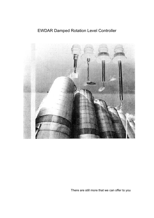
EWDAR Damped Rotation Level ControllerThere are still more that we can offer to youSincere services to clients:With the increasing competition in the market, instruments that are accurate in measuring and free of maintenance can help to improve the production efficiency of the factories. EWDAR level control system is such a product that can substantially improve the product quality and work efficiency of your company. We are always available to supply standard products or provide tailor-made products in response to your requirement for various application of EWDAR level measuring products in such industries as power, cement, engineering machinery, casting, chemical and food processing etc. In addition to the excellent measuring technology, EWDAR will always provide high-quality services to all clients.1、Applications and characteristics:EWDAR series damped rotation level control system has wide applications in the modern industry production process and warehousing sector for level monitoring or control of the powder and grain substances in the open type vessels. With full new design concept introduced in the product and many years of successful experiences, EWDAR series damped rotation level control system features extreme low failure and unanimous positive comments from the clients of all walks of life. EWDAR series damped rotation type level control system features advanced technology, reasonable structure, reliable performance, easy and convenient use and maintenance as well as high cost performance etc; Compared with similar products in the market, EWDAR level control system has the following unique characteristics:1) All major exposed parts and components use such materials as stainless steel,aluminum alloy or high-grade engineering plastic featuring such outstanding advantages as dust-proof, moisture resistance, corrosion resistance and no pollution to environment. EWDAR may be used in severe working environment in such industries as power, cement, casting, concrete, asphalt mixing equipments, food processing, grain warehousing and industries with high produce of dust etc;2) The output shaft is equipped with overload protection device, which caneffectively avoid damages to the motors and speed reducers due to improper use or abnormal external force;3) In order to make the equipment suitable for different materials with differentspecific gravity and also for purpose of easy installation and adjusting, the equipment is provided sensitive five-gear adjusting device and two installation options as well as many monitoring vane specifications;4) ZXKHB type level control system is equipped with overheat protection device,which can ensure proper and normal working of the level control at temperature of 300℃and below. (This ability is out of reach of some capacitor type, pitchfork type and ultrasonic type level monitors);2、Working principle:The working principle of EWDAR series damped rotation type level controller isdescribed as following: Use of AC micro motor with speed reduction to drive the monitoring vane rotate at slow speed; when the level of the materials rises till the rotation of the vanes is blocked, the testing mechanism will have rotation displacement around the main shaft; this displacement will first put one micro switch in action to send signal that material is fed inside; and then the other micro switch will act to disconnect the power supply to the micro motor to stop the motor; as long as the level in the silo or container remains unchanged, this work status will be always maintained;When the material level decreases till the vanes are tested with no blockage, the testing mechanism will restore to the original state due to pull force of the spring. First one micro switch will act to switch on the power supply to the motor to make the motor run, then the other micro switch will act will send signal that material is in shortage; as long as the rotation of the vanes will not be blocked by the materials, this work status will be always maintained.3、Outline dimensions:1) Outline dimensions ( Figure 1)2) Outline dimensions (Figure 2):4、Main technical specification:5、Type selection of damped rotation type level control system:Thread connectionFlange connectionLength6、Installation guideline:Unit: mmSilo wallTailor-made dimension may be available upon client’s request!。
- 1、下载文档前请自行甄别文档内容的完整性,平台不提供额外的编辑、内容补充、找答案等附加服务。
- 2、"仅部分预览"的文档,不可在线预览部分如存在完整性等问题,可反馈申请退款(可完整预览的文档不适用该条件!)。
- 3、如文档侵犯您的权益,请联系客服反馈,我们会尽快为您处理(人工客服工作时间:9:00-18:30)。
第 2 页共 83 页旧底图总号底图总号签字日期1 概述1.1用途及应用范围WYD-804微机远动装置适用于500kV及其以下电压等级变电站、电厂等自动化系统,将采集到的系统数据通过电力线或光纤等通讯介质用约定的通讯规约传送到远方控制中心。
2 装置结构及工作原理•装置核心采用具备工业104扩展总线主板;•面板提供基本的运行状态指示灯,复位、远方/就地按钮;•背板上提供8个RS-232/422/485接口,三个10M/100M自适应RJ-45以太网接口;•提供PC机监视调试软件;•内置webserver,可以远程浏览监视装置的运行状态;•内置工业104总线,预留扩展功能。
3 技术指标3.1 基本数据供电电源:24 V、1.5 A。
串口:8个串口。
LAN: 提供三个10/100M Base RJ-45端口。
3.2 功率消耗:最大35W。
3.3 机械性能a. 工作条件:能承受严酷等级为Ⅰ级的振动响应、冲击试验。
b. 运输条件:能承受严酷等级为Ⅰ级的振动耐久、冲击及碰撞试验。
3.4 环境温度工作:-10℃~+55℃。
贮存:-25℃~+70℃在极限值下不施加激励量,装置不出现不可逆变化,温度恢复后,装置还能正常工作。
3.5 大气压力:80kPa~110kPa(相当海拔高度2km及以下)。
3.6 相对湿度:最湿月的月平均最大相对湿度为90%,同时该月的月平均最低温度为25℃且表面无凝露。
3.7 电磁兼容:静电放电抗扰度试验能承受严酷等级为III级的干扰试验;射频电磁场辐射抗扰度试验能承受严酷等级为III级的干扰试验;电快速瞬变脉冲群抗扰度试验能承受严酷等级为III级的干扰试验;第 3 页共 83 页旧底图总号底图总号签字日期浪涌(冲击)抗扰度试验能承受严酷等级为III级的干扰试验;射频场感应的传导骚扰抗扰度试验能承受严酷等级为III级的干扰试验;工频磁场扰抗扰度试验能承受严酷等级为III级的干扰试验;脉冲磁场抗扰度试验能承受严酷等级为III级的干扰试验;阻尼振荡磁场抗扰度试验能承受严酷等级为III级的干扰试验;电压暂降、短时中断和电压变化试验能承受GB/T17626.11-1999规定电压中断为100m s、电压暂降40%为1S的干扰试验;高频抗扰度试验能承受严酷等级为III级的干扰试验。
3.8产品通用标准和其它主要的现行技术标准GB/T 7261-2000 继电器及装置基本试验方法GB/T 13729-2002 远动终端设备GB/T17626.2-1998 电磁兼容 试验和测量技术 静电放电抗扰度试验(idt I EC61000-4-2:1995)GB/T 17626.3-1998 电磁兼容 试验和测量技术 射频电磁场辐射抗扰度试验(idt I EC61000-4-3:1995) GB/T 17626.4-1998 电磁兼容 试验和测量技术 电快速瞬变脉冲群抗扰度试验 (idt I EC61000-4-4:1995) GB/T 17626.5-1999 电磁兼容 试验和测量技术 浪涌(冲击)抗扰度试验(idt I EC61000-4-5:1995)GB/T 17626.6-1998 电磁兼容 试验和测量技术 射频场感应的传导抗扰度试验 (idt I EC61000-4-6:1995) GB/T 17626.8-1998 电磁兼容 试验和测量技术 工频磁场抗扰度试验(idt I EC61000-4-8:1993)GB/T 17626.9-1998 电磁兼容 试验和测量技术 脉冲磁场抗扰度试验(idt I EC61000-4-9:1993)GB/T 17626.10-1998 电磁兼容 试验和测量技术 阻尼振荡磁场抗扰度试验(idt I EC61000-4-10:1993) GB/T 17626.11-1999 电磁兼容 试验和测量技术 电压暂降、短时中断和电压变化抗扰度试验(idtI EC61000-4-11:1994)GB/T 17626.12-1998电磁兼容试验和测量技术振荡波抗扰度试验(idt I EC61000-4-12:1995)DL/T 451-1991 循环式远动规约DL/T 634.5101-2002 远动设备及系统第5-101部分:传输规约基本远动任务配套标准(idtI EC60870-5-101:2002)DL/T 634.5104-2002 远动设备及系统 第5-104部分:传输规约 采用标准传输协议子集的I EC60870-5-101网络访问(idt I EC60870-5-104:2000)Q/XJ 20.50-2004 继电器、保护及自动装置通用技术要求第 4 页共 83 页旧底图总号底图总号签字日期4 概述4.1 路径与系统硬件配置说明4.1.1 运行所需文件及路径正确安装后下列文件及目录存放在C:\P rogr am Files\RTU目录下,不能删除:dbserver.exe\\实时数据库rtuserver.exe\\规约服务器rtut k.exe\\参数设置及调试工具箱(人机界面) t m edit.exe\\定值模板库生成工具(人机界面) netrule.d a t\\以太网规约选项c k rule.d a t\\串口规约选项exec\\\规约库edit\\\数据库保存目录cfg\\\rtuserver所需数据配置文件目录 rtdb\\\dbserver所需数据配置文件目录 log\\\记录相关操作和报文的目录help\\\联机帮助和其它帮助文件目录动态链接库存放于C:\W I NNT\syste m32路径下:dblib.dll\\数据库访问的接口函数库Api232.dll\\串口访问函数库下列路径为自动生成的规约存放路径,也存放在RTU目录下:ch1\…ch7\4.1.2 edit目录说明:cl\\\测量库k g\\\开关量库m c\\\脉冲库soe\\\SOE库y k\\\遥控库dz\\\定值库第 5 页共 83 页旧底图总号底图总号签字日期res\\\增加数据库所必须的资源文件Te m p\\\存放临时I ni文件Te m plet\\\模板库内容4.1.3 基本配置:微处理器主频400MHZ,内存为256M,存储Fl a sh卡64M,3个以太网接口(RJ45),8个RS232/485/422口,一个VGA接口,一个鼠标、键盘二合一接口,两个USB接口。
预装W I NDOWSCE4.2操作系统。
4.2 网络设置4.2.1 设定系统IP设定系统的IP地址有两种方法:4.2.1.1 通过外接显示器、键盘、鼠标方式设定设定方式与Windows IP地址设定方式一致。
在设定IP地址完毕后,需要运行一下regs a ve命令,将IP地址保存到注册表中。
4.2.1.2 通过网页设定使用本方法设定IP地址,需要预先知道一个IP地址(出厂网口1的默认IP地址为10.100.100.6)。
将外部计算机与WYD-803装置通过网络连接,在I E中输入http://IP地址/networ ka d m in回车如图4-1所示图4-1 网络设置IP地址登陆图用户名:admin 密码:admin, 单击确定后进入设置界面如下图所示:第 6 页共 83 页旧底图总号底图总号签字日期图 4-2网络设置IP地址主界面图选择Advanced Setting项目,打开界面如下图所示:图 4-3 网络设置IP地址网卡选定界面图 选择要设定的网卡后,切换到NetWork界面,如下图所示:第 7 页共 83 页旧底图总号底图总号签字日期图 4-4 网络设置IP地址界面图4.2.2程序配置文件中的所需IP1.运行rtut k.exe,打开RTU检测与设置程序,点击工具栏中的“站内设置”按钮,输入正确的密码后弹出“站内参数设置”窗口,如图4-3所示:图4-5 “站内参数”设置窗口,接,接状态,接,图5-1 RTU监测与配置主界面图5-2 站内参数设置窗口图5-3 双机切换串口参数配置窗口两次切换的最小时间间隔,在这个间隔时间图5-4 通道参数配置窗口“参数配置”的窗口中,根据工具栏中当前通道选择下拉菜单选择所要配置通道。
修改和配置各种转发编号’可以修改,推荐保证每个间隔的相同库内的系统编号不能重复。
在转发库里,各通道内的数据生成数据库)中的数据参数完全相同,但系统编号是自动生成的。
每次新建装置时,新建的系统编号第 11 页共 83 页旧底图总号底图总号签字日期一次生成的数据库内的最大系统编号加2开始安排的。
对此有一些技术参数指标要求,即:模拟量库、开关量库、SOE 库、遥控库和脉冲库的最大系统编号不能超过32767,如果超过会带来不可预知的错误。
转发表中的转发顺序是与这里的系统编号有关的,系统编号小的排在转发表的前面。
系统编号的顺序也可以随意修改。
如果想修改或调整远动转发表中的转发顺序,只要修改或调整这里对应的系统编号即可。
遥信库中“SOE”,当为正常遥测时,该项均为FALSE,只有需要该遥信量变位时触发SOE上送时才需要选为TRUE,与其相对应的点在转发表中的“SOE编号”不为“-1”时,即表示该点被选为触发SOE了。
这时如果有该点的遥信变位上送,则同时会上送一个SOE到调度端,其编号即为遥信转发表中所对应的“SOE编号”。
在“模拟量库”中,“偏移”是模拟量加上该值才能正确反映该数据;“装置乘系数”、“装置除系数”是因为装置上传的数据是经过一定的处理后才上传的。
为了显示正确的数据需要对其进行相应装置系数的处理。
因此另附一张装置系数说明的表格,根据表格来填写该项;“规约量程”、“变比”是为防止数据在传输中溢出所进行的数据转换。
这里给出公式便于大家计算:实际二次值=现场104规约报文值*装置乘系数/装置除系数远动报文值=实际二次值*规约量程/装置乘系数规约系数=装置乘系数/规约量程调度系数=规约系数*变比调度端显示值=实际报文值*调度系数在浏览数据中,所看到的遥测值为:数值=现场104规约报文值*装置乘系数/装置除系数+偏移量在开关量库中,“单双点”是指该点是单点遥信还是双点遥信,“0”表示单点遥信,“1”表示双点遥信。
“级别”是表示该点是属于故障信号呢还是告警信号,分为“事故”、“告警”和“正常”,“事故”表示是故障信号即该信号发生后上传“事故总信号”,“告警”表示告警信息即该信号发生后上传“预告总信号”,“正常”表示此信号为正常变位即不启动“事故总信号”和“预告总信号”。
注意:1.在各库中需要发送的量一定要在“是否发送”项后打勾即选中转发。
2.配置完成后要“更新系统”才生效。
5.2.3 数据库配置图5-4中左边成树状显示的即为不同的网关,他们的名称就是新建网关时的网关名称。