脉冲噪声的正确测量与评价方法
纹波和噪声
开关电源的纹波和噪声(图) 日期:2009-08-26 来源:本网作者:北京航空航天大学方佩敏开关电源(包括AC/DC转换器、DC/DC转换器、AC/DC模块和DC/DC模块)与线性电源相比较,最突出的优点是转换效率高,一般可达80%~85%,高的可达90%~97%;其次,开关电源采用高频变压器替代了笨重的工频变压器,不仅重量减轻,体积也减小了,因此应用范围越来越广。
但开关电源的缺点是由于其开关管工作于高频开关状态,输出的纹波和噪声电压较大,一般为输出电压的1%左右(低的为输出电压的0.5%左右),最好产品的纹波和噪声电压也有几十mV;而线性电源的调整管工作于线性状态,无纹波电压,输出的噪声电压也较小,其单位是μV。
本文简单地介绍开关电源产生纹波和噪声的原因和测量方法、测量装置、测量标准及减小纹波和噪声的措施。
纹波和噪声产生的原因开关电源输出的不是纯正的直流电压,里面有些交流成分,这就是纹波和噪声造成的。
纹波是输出直流电压的波动,与开关电源的开关动作有关。
每一个开、关过程,电能从输入端被“泵到”输出端,形成一个充电和放电的过程,从而造成输出电压的波动,波动频率与开关的频率相同。
纹波电压是纹波的波峰与波谷之间的峰峰值,其大小与开关电源的输入电容和输出电容的容量及品质有关。
噪声的产生原因有两种,一种是开关电源自身产生的;另一种是外界电磁场的干扰(EMI),它能通过辐射进入开关电源或者通过电源线输入开关电源。
开关电源自身产生的噪声是一种高频的脉冲串,由发生在开关导通与截止瞬间产生的尖脉冲所造成,也称为开关噪声。
噪声脉冲串的频率比开关频率高得多,噪声电压是其峰峰值。
噪声电压的振幅很大程度上与开关电源的拓扑、电路中的寄生状态及PCB的设计有关。
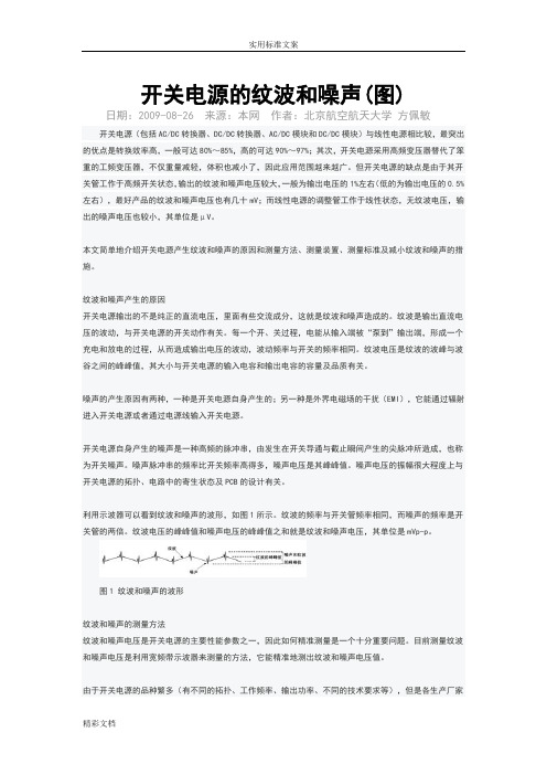
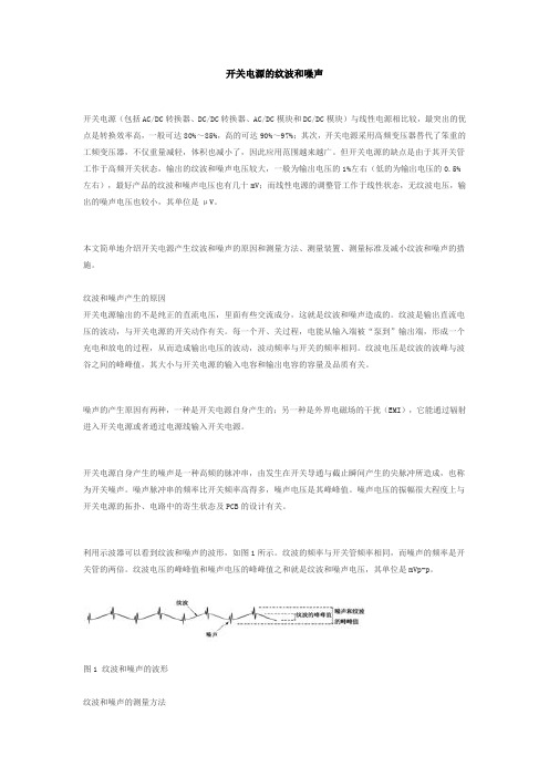
利用示波器可以看到纹波和噪声的波形,如图1所示。
纹波的频率与开关管频率相同,而噪声的频率是开关管的两倍。
纹波电压的峰峰值和噪声电压的峰峰值之和就是纹波和噪声电压,其单位是mVp-p。
噪声的评价和测量

评价工作程序 建设项目工程概况(参阅有关文件) 评价范围内现场踏勘
确定噪声环境影响评价工等级,编写环境影响评价大纲——噪声部分 环境噪声现状调查和测量
噪声源调查 环境噪声现状调查及测 量
受影响人口调 查
建设项目工程分析(与噪声有关 的内容)
环境噪声现状评价
噪声级预测、受影响人口预测
噪声管理法规与标准
定点测量方法:
24小时连续监测,测量每小时的连续等效声级,昼间A声级能量平均值,夜间A声级能量 平均值,
该区的环境噪声水平由下式计算:
L
n i 1
Li
Si S
(2)道路交通噪声测量
测点:市区交通干线(机动车流量不小于100辆 )一侧的人行道上,距马路沿20cm处,此处距两交 叉路口应大于50cm
lg
r 1 r0
acr
tan
2r
l0 2r0
• r>l0且r0>l0时 • L(r)= L(r0)-20lg(r/r0) • r<l0/3且r0 <l0/3时 • L(r)= L(r0)-10lg(r/r0)
(2)遮挡物引起的衰减 (3)空气吸收引起的衰减 (4)附加衰减
• 2、公路噪声预测
噪声环境影响评价
噪声防治对策
噪声影响评价专题报告
噪声环境影响评价工作等级划分基本原则
划分依据: • 投资额划分建设项目规模(大、中、小) • 噪声源的种类及数量 • 项目建设前后噪声级的变化程度 • 建设项目噪声有影响范围内的环境保护目标、环境噪声标准和人口分布
级别
项目规模 受影响范围属于的功能区 建设前后噪声级的变化 受影响的人口
LI=LW-10lgS=LW-10lg(2πr2) =LW-20lgr-8
噪声修正标准
噪声修正标准噪声是指在信号中不希望出现的干扰成分,它会使得原本清晰的信号变得模糊不清,影响信号的传输和处理。
在实际的工程应用中,噪声修正是非常重要的一项工作,它能够提高信号的质量,使得信号更加可靠和准确。
因此,噪声修正标准的制定和执行对于各个领域的工程技术人员来说都是至关重要的。
首先,噪声修正标准需要明确噪声的类型和特性。
根据噪声的特性和来源,可以将噪声分为各种不同的类型,比如加性噪声、乘性噪声、高斯噪声、脉冲噪声等。
每种类型的噪声都有其特定的数学模型和统计特性,因此需要根据具体情况选择合适的噪声修正方法和标准。
其次,噪声修正标准需要明确修正的目标和要求。
不同的应用场景对于信号质量的要求是不同的,有些场景对于噪声的容忍度较高,而有些场景则要求对噪声进行严格的修正。
因此,在制定噪声修正标准时,需要明确修正的目标和要求,确定修正后信号的质量指标和评价标准。
然后,噪声修正标准需要选择合适的修正方法和算法。
针对不同类型的噪声,有各种不同的修正方法和算法可供选择,比如滤波算法、降噪算法、补偿算法等。
在选择修正方法和算法时,需要考虑到信号的特性、噪声的特性以及修正的要求,综合考虑各种因素来选择最合适的修正方法和算法。
最后,噪声修正标准需要进行实际的验证和评估。
制定了噪声修正标准之后,需要进行实际的工程应用和验证,评估修正后的信号质量是否符合标准要求。
如果修正后的信号质量不符合要求,需要对修正方法和算法进行调整和优化,直到达到标准要求为止。
总之,噪声修正标准的制定和执行对于提高信号质量和保障工程应用的可靠性至关重要。
通过明确噪声的类型和特性、明确修正的目标和要求、选择合适的修正方法和算法、进行实际的验证和评估,可以制定出科学合理的噪声修正标准,提高信号的质量,保障工程应用的可靠性和稳定性。
基于模糊熵的数字图像脉冲噪声检测与校正方法(IJIGSP-V10-N3-5)
I.J. Image, Graphics and Signal Processing, 2018, 3, 36-46Published Online March 2018 in MECS (/)DOI: 10.5815/ijigsp.2018.03.05Fuzzy Entropy based Impulse Noise Detection and Correction Method for Digital ImagesS.Vijaya KumarResearch Scholar, Dept of CSE, JNTU Hyderabad, Telangana,Email: svksr105@C.NagarajuAssociate Professor,YSR Engineering College of Yogivemana University, Proddatur, A.PEmail: cnrcse@Received: 08 December 2017; Accepted: 30 January 2018; Published: 08 March 2018Abstract—Impulse noise is the prime factor which reduces the quality of the digital image and it erases the important details of the images. De-noising is an indispensable task to restore the image features from the corrupted low- quality images and improve the perceptual quality of images. Several techniques are used for image quality enhancement and image restoration. In this work, an image de-noising scheme is developed to detect and correct the impulse noise from the image by using fuzzy entropy. The proposed algorithm is designed in two phases, such as noise detection phase, and correction phase. In the noise detection phase, the fuzzy entropy of pixels in a window of interest (WoI) is computed to detect whether the pixel is noisy or not. The Fuzzy entropy of pixel greater than specified alpha cut value will be considered as noise pixel and submitted to correction phase. In the correction phase noise pixel value is replaced with a fuzzy weighted mean of the un-corrupted pixels in the WoI. The proposed Fuzzy entropy based impulse noise detection and correction method are implemented using MATLAB. The experimentation has been carried out on different standard images and the analysis is performed by comparing the performance of the proposed scheme with that of the existing methods such as DBA, MDBUTMF, AMF, NAFSM, BDND, and CM , using PSNR, SSIM, and NAE as metric parameters. The proposed method will give good results compared to state of the art methods in image restoration.Index Terms—Fuzzy entropy, a window of interest, impulse noise, image restoration.I.I NTRODUCTIONWith the advent and usage of multimedia, visual data from quality digital images play a significant role in human day to day life applications. Unfortunately, images which are captured through many cameras have been generally subjected to the contamination of impulse noise. Generally impulse noise caused by malfunctioning pixel sensors, defective memory units, and imperfections encountered in a channel for the duration of transmission and timing errors in analog-to-digital conversion [1-4]. Before successive digital image processing operations, restoring of the corrupted image has been accomplished as the first step in digital image processing.Image restoration is imperative for successive tasks (e.g., edge detection, image segmentation, classification, parameter estimation, etc.) which are basically affected by the quality of the image. Capturing devices has become sensitive to the acquaintance of impulse noise due to more sensing elements per unit space are integrated on a single chip. To overcome this, digital camera manufacturing companies rely on restoration methods to enhance the visual quality of the image acquired. As a result, a number of methods have been proposed for the removal of impulse noise. Non-linear filters are superior to linear filter with their great execution to restoring the image from impulse noise, For instance, the median filter [2],[5] could be a natural selection for suppressing impulse noise. The idea of a median filter is to replace the window pixel given by the median of the brightness in the window. The Median filter gives the better results at low noise levels (<10%)[12] but it alters the image pixels even though it is not corrupted, this led to bad result at high noise levels (>10%)[12], the key image details are also decorated. This problem has led to the development of various classes of filters, such as the weighted median-filters [1], [2], [4]-[7], [9], adaptive filters [8],[12], and rank-ordered statistics, switching median filter and soft computing filters [9-14],[16], [28-29].By adapting these non-linear filters, the restoration quality Significantly increases but the implementation and time complexity is multiplied and hardware cost also increases. In this paper, we propose a new filtering mechanism is proposed for high impulse noise removal with less computational cost using fuzzy entropy. The proposed technique restored the digital image with less computational time and it simultaneously maintaining edge information compare with different existing filters.II. I MPULSE N OISE M ODELSIn this section, impulse noise models are clearly described. A digital image of size RxC stored as an 8-bit gray level image and the image elements are lie in the range [0,255]. In this, least and highest intensity values are 0 and 255. Regardless of its origin, impulse noise shows non stationary measurable qualities [1], [3] and just a specific percentage of pixels in the digital images are corrupted by impulse noise [12]. In view of this reality, the models for impulse noise with probability P defined in[12] as, _(,)02_(,)1, _(,), _(,)2552Pfor In Image i j SNP Image i j P for In Image i j Pfor In Image i j ⎧=⎪⎪=-⎨⎪⎪=⎩ (1)where the P is the noise probability densityNoise Model-I1 , _(,)0_(,)1, _(,)2 , In_Image(,)255P for In Image i j SNP Image i j P for In Image i j P for i j ==-=⎧⎪⎨⎪⎩ (2)where the P is the noise probability density P=P1+P2 andP1≠P2Noise Model-IIIn the literature, usually two impulse noise models: salt-and-pepper (SNP) noise and random-valued impulse noise. Which are used as a part of image processing. In the SNP noise the image intensity values are set to be 255(salt) that is all the bits in gray level set to be one and 0(pepper) that is all the bits in gray level set to be zeros. In random-valued impulse noise model, the image intensity values are set to be any value within the dynamic range [0,255].In the real world scenario, impulse noise is generated from the overlapping of impulse noise signals with random amplitudes. As a result, the impulsive amplitude could both fall within the image dynamic range or out of that range. While the impulsive amplitude lies outside of the dynamic range, the resultant pixel might be saturated and threshold to the 255 or 0 intensity value of the image and looks as SNP noise. On the other hand, if the impulsive amplitude lies in the dynamic range, the resultant pixel seems as uniform noise (UNIF) noise within the image.The noise model-I is SNP model with equal probability as represented in equation-1 and Noise Model II is similar to model-II, except that salt noise and pepper noise are with unequal probability as represented in equation-2., 0 _(,)2_(,)1, _(,), 255-< _(,)2552Pfor In Image i j M M Unif Image i j P for In Image i j P for M In Image i j M ⎧≤<⎪⎪=-⎨⎪⎪≤⎩(3) where the P is the noise probability density Noise Model-III1, 0 _Im (,)_Im (,)1, _Im (,)2, 255- _Im (,)255P for In age i j M M Unif age i j P for In age i j P for M In age i j M ⎧≤<⎪⎪=-⎨⎪⎪<≤⎩(4)where the P is the noise probability density P=P1+P2 and P1≠P2Noise Model-IVThe noise model-III is UNIF model with equal probability as represented in equation-3 and Noise Model IV is similar to model III, except that salt noise and pepper noise are with unequal probability as represented in equation-4.III. F UZZY E NTROPY M EASURE FOR I MPULSE N OISEI DENTIFICATIONS An image X of size RxC having L gray levels ranging from L min to L max can be defined as an array of fuzzy singletons .Each element in the array is the membership function value representing its degree of brightness relative to gray level l (l = L min , L min + 1, . . . , L max ). Therefore, in fuzzy set notation, we can write{(,)/(,), 1,2,3,4,.........,; 1,2,3,4,.....,}X p i j p i j i R j C μ=== (5)()2(,)-22 (,)p P i j p e i j σμ-= (6)Where1(,)11m np i j P i j mn σ∑∑=-==(7)Where111(,)m ni j P p i j mn ===∑∑(8)From the entropy concept, we know that fuzzy entropy [17-22],[27] is less for orderly image pixel values and more for disorderly image pixels. If we try to visualize the image data, information pixels are orderly configured and impulse noise pixels are disorderly configured. So if we evaluate the fuzzy entropy at each image pixel then the image pixel with minimum fuzzy entropy is an informative pixel and with higher fuzzy entropy is an impulse noise pixel.The fuzzy entropy value of pixel in given a window of interest can be calculated as given in equation-5 ()()()()()()()log 2(1)log 2(1),01p p p ii i p p i i p i μμμμμμE =----≤≤ (9)The fuzzy entropy value of the image pixels in the given window is in the range [0.0-1.0].Fuzzy Entropy Value is low for the pixel, which lie between 0 and 255 and very high (close to 1) for the 0 and 255. Fuzzy entropy assumes the maximum value of 1.0 when((,))p i j μ is 0.5 and a minimum value of 0.0 when ((,))p i j μ is 0.0 or 1.0[22].IV. I MPULSE N OISE D ETECTION M ETHOD U SING F UZZYE NTROPY M EASURE This section describes the Fuzzy Entropy Based Impulse Noise Detection (FEIND) algorithm and then discusses the some of the implementation issues of the algorithm. The algorithm-I is used to detect the pixel is impulsive or not with fuzzy entropy. The basic working principle of an algorithm-I is that, given image convert into the fuzzy plane using the Gaussian membership function, then compute the fuzzy entropy of image pixels using the equation-5.A greater difference of the values among the evaluation pixels results in a higher fuzzy entropy and pixel values which are similar in the window results in lower fuzzy entropy. Using this underlying idea the pixels can be classified as corrupted or uncorrupted. To identify given pixel in the window of interest (WoI) is impulsive or not, calculate the fuzzy entropy of processing pixel in the WoI and check whether the fuzzy entropy of pixel is greater than the given alpha cut value. If it is greater than the given alpha cut value then it is impulsive and submitted to correction phase. Skelton of the noise detection is given in algorithm-I.A. Impulse Noise Detection Method Using Fuzzy Entropy MeasureFEIND method keeps its original value as it is in the processed image if it detects the pixel values is informative. Only impulse noise pixels are submitted to correction phase, which is similar to traditional switching filters. Traditional switching filters first identify the noise pixels and form the binary noise map of the image to record the information of impulse noise such as noise pixel location. Fuzzy weighted mean filter corrects the noise pixel one after another using the information in noise map and it leads to increase of CPU time and require more main memory space. To overcome this drawback, the FEIND filter corrects the impulse noise immediately after the pixel has been detected as an impulsive candidate. Hence, in the FEIND filter, for thenoise detection and the correction use the same window of interest. The details are shown in the algorithm-I.V. R ESULTS AND D ISCUSSIONSIn this section, from the experimental study we are going to address the following two points:1. FEIND method can identify the impulse noise pixels in given image2. Restore the corrupted pixel value with the fuzzy mean of uncorrupted pixels in WoI.In order to accomplish the tasks, we use Lena, Parrot, and bridge corrupted mages with impulse noise model-I, noise density range from 30% to 90%. To show FEIND is able to detect the impulse noise candidate, we experimented with different window size on various noise levels by choosing the different alpha cut values range from 0.1 to 0.9. The Fig.1 Depicts the input 7x7 image with 70% of impulse noise and Figure.2 represent the fuzzy entropy of the corrupted image. From the Table-I we can conclude that the pixels with intensities 0 and 255 having greater fuzzy entropy than the remaining pixels. The pixel is treated as a noise pixel if it having greater fuzzy entropy than the specified alpha cut value and it is submitted to next filtering stage. Otherwise, the pixel is treated as informative pixel and it keeps as it is in the processed image. Table IV, Table V, Table VI and Table VII lists the accuracies of identification of the noise pixels with various window sizes, which are defined using two factors. One is the number of missed detections (MD), namely, the number of noise pixels that are identified as uncorrupted pixels. The other one is the number of false alarms (FA), i.e., the number of uncorrupted pixels that are identified as noise pixels [12]. Among the filtering windows, the 7x7 has less MD and Algorithm-I{}p i,j p i,1mn j =p -M?a,b?Mi+a,j+For every pixel image do1. Get region R for image pixel by taking M=4M P i,j2. Calculate the sample mean of the Region p, i b m n¬p(i,j)i=1j=1.e.,3. Calcul - p ∑∑()ate the Standard Deviation of the Region p, i.e.,, i.e.,i,j 2p -P i,j -2 μ(p )m n1 σ×p(i,j)-P i =e 2σi,j 5. Calculat =1j=1e the ∑∑()()()()()()()()()p i,j fuzzy entropy of the processing pixel p , i.e.,i,j p p p p p p i,j i,j i,j i,j i,j i,j 6. if p T theni,j p p ,continuei,j i,j 7. else8.Εμ=-μlog2μ-(1-μ)log2(1-μ) is corrupted with impulse ,0 μ1Εμ<=noise ≤≤Algorithm-IIp 1. Calculate the sample mean of the pixels in the Region 2. Calculate the Standard Deviation i.e.,m n1¬p(i,j)i=1j=1m n1 σ×p( 3. Calculate the fuzzy mem i,j)-Pi=1j=b 1ers p, i.e.,∑∑∑∑()()()()()()()()()()hip of the pixels in t p , i.e.,i,j 2p -P i,j -2μ(p )=e 2σF i 4. Calculate the fuzzy entropy of the processing pixel p , i.e.,i,j p p p p p p i,j i,j i,j i,j i Εμ=-μlog2μ-(1-μ)log2(1-μ),j i,j 5. if ,0μ1Εμ<p T i,j ≤≤() then2p -P i,j -2fuzzy weights of uncorrupted pixel is w =μ(p )=e2σi i,j pute the fuzzy weighted mean of uncorrupted pixel, i.e.,ny =p * μ(p )i,j i i i=1where n= number of un-corrupted pixels in the regi ∑on of interestFA (see Table-III&VIII) at the alpha cut value in between 0.5 to 0.6. Therefore, image restoration using 7x7 window gives the better visual quality than the remaining windows. All the windows up to 0.4 alpha cut value gives the zero false alarms but gives more missed detections. For the 60% and 80% impulse noise, the window size 5x5 with alpha cut vale 0.6 gives the least missed detection and zero false alarms. The window size 7x7 with alpha cut vale 0.5 gives the least missed detections and zero false alarms for the noise densities range from 30 to 90.The window size 9x9 with alpha cut value 0.6 gives the least missed detections and zero false alarms for the noise density 60% and gives the zero missed detection and least false alarms for the noise density 70%.From the Tables IV to VII finally concluded that the alpha cut value between 0.5 to 0.6 with window size 7x7 gives least missed detections and false alarms. Table-IX shows the identification time required to classify the noisy pixel and information pixel using various windows. From the above analysis we concluded that the window size 5x5 gives least computational time and 11x11 gives the more computational time. From the table-VII, For the 90% of impulse noise with Window size 7x7 and alpha cut value 0.5100 gives zero MD and zero FA. For the 80% of impulse noise with Window size 7x7 and alpha cut value 0.5500 gives zero MD and zero FA. For the 70% of impulse noise with Window size 7x7 and alpha cut value 0.5980 gives zero MD and zero FA. For the 60% of impulse noise with Window size 7x7 and alpha cut value 0.5996 gives zero MD and zero FA. For the 50% of impulse noise with Window size 7x7 and alpha cut value 0.5768 gives zero MD and zero FA. Table-IV describes the Computational require to classify the pixel with various window sizes 5X5 to 11X11.77255012610810512500255107025525512418613802552551350025525502550025501502551520255255255255255002552552552550127X P ⎡⎤⎢⎥⎢⎥⎢⎥=⎢⎥⎢⎥⎢⎥⎢⎥⎣⎦Fig.1. Input 7x7 image corrupted with 70 %of salt and pepper noise.Table 1. Fuzzy entropy of the each pixelFrom that, window size 7x7 requires average less computational time to classify the pixels with the noise density ranges from 30% to 90%.Restoration performance of proposed method implemented using standard gray scale images of size 256x256 with 8-bit resolution. Each of the test images is degraded with Noise Model-I and noise density ranging from 10 % to 90 % in 10% noise step. For comparison, degraded images also restored using the existing filters adaptive median filter (AM), Decision-Based algorithm for Impulse Noise Removal(DBA)[13], DBUTMF[14],NAFSM[11],boundary discriminative noise detection (BDND)[12] and cloud model filter(CM)[16]. AM utilizes the adaptive window mechanism for recognizing.Corrupted and uncorrupted pixels, next to the filtering approach, was applied, for AMF initial window size is 3x3 consider and incrementing the window size maximum to 39 with 2 in step.The DBA is implemented with the 3x3 window, it removes only corrupted pixel by the median value of its neighboring pixels. For the BDND in the first iteration, the window size 21x21is used, if it fails to find the impulse noise, conditionally invokes the second iteration with window size 3x3 Initial window size of 3x3 to maximum window size of 13x13 with 2 step increment is used to implement the CM.For the FEIND filter window of interest, 7x7 is used for pixel classification.Table I & II are show the restoration results of the Lena image corrupted with noise density range from30 % of impulse noise to 80% impulse noise in terms of PSNR, [27] and NAE. The table values show that the proposed method gives good performance compare to existing filters. In other two images house and parrot the proposed method gives the better results compare to AM, DBA, MDBUTMF and NASFM and gives average performance compare to BDND and CM filters. Fig.3.a shows original Lena and parrot images, Fig.3.b represents the images corrupted with 30% impulse noise, Fig.3.c represent the noise image with 60 % impulse noise and Fig.3.d represents the noise images with 80% impulse noise.Fig.4 to Fig.8 illustrate the visual quality of the restored images of filters DBA, DBUTM, AMF, NAFSM, BDND, CM and proposed method. Fig. 4 and Fig.8 conclude that all the filters exhibit almost similar visual quality at 30% noise level, from the Fig.5 and Fig.8 we conclude that the visual quality of the DBA method is poor at noise level 60%, and proposed method provides the better visual quality compared to remaining state of art algorithms. From the Fig.6 and Fig.9, we conclude that the DBA, MDBUTMF and AMF filters provide the poor visual quality at noise level 80% and NAFSM, BDND methods provide better visual quality compare to DBA, DBUTMF and AMF filters, CM and proposed methods give best visual quality compared to remaining all the methods.Table 2. Comparison of Noise Detection Accuracy in MD And FA In 5x5 For Lena Image at Various Alpha Cut ValuesTable 3. Comparison of Noise Detection Accuracy in MD and FA in 7x7 For Lena Image at Various Alpha Cut ValuesTable 4. CPU Time In Seconds For Bridge ImageTable 5. Comparison of Noise Detection Accuracy In MD and FA in 9x9 For Lena Image at Various Alpha Cut ValuesTable 6. Comparison of Noise Detection Accuracy In MD And FA in 11x11 For Lena Image at Various Alpha Cut ValuesTable parison Of Zero MD and FA For Lena Image At Different Alpha Cut Values For Various Noise Densities With Window Size 7x7Table parison of Noise Detection Accuracy In MD And FA in 7x7 For Bridge Image At Various Alpha Cut ValuesTable 9. Comparison Of Restoration Results For ‘Leena’ Test Image In Psnr (Db) And NAETable10. Comparison Of Restoration Results For ‘House’ Test Image In PSNR (Db) and NAETable 11. Comparison Of Restoration Results For ‘Parrot’ Test Image In Psnr (Db) And Mae(a)(b)(c)(d)Fig.3.a) Original images b)Images corrupted with 30% noise c) Images corrupted with 60% noise d) Images corrupted with 80% noise(a)(b)(c)(d)(e) (f) (g) Fig.4. Results of denoising corrupted image “Lena,” with 30% impulse noise density (a)DBA (b)MDBUTMF(c)AMF(d)NAFSM(e)BDND(f)CM And (g)FEIND(a) (b) (c)(d)(e) (f) (g)Fig.5. Results of denoising corr upted image “Lena,” with 60% impulse noise density (a) DBA (b) MDBUTMF (c) AMF (d) NAFSM (e) BDND (f)CM and (g) FEIND(a) (b) (c)(d)(e) (f) (g)Fig.6. Results of denoising corrupted image “Lena,” with 80% impulse noise density (a) DBA (b) MDBUTMF (c) AMF (d) NAFSM (e) BDND (f)CM and (g) FEIND(a) (b) (c) (d)(e) (f) (g)Fig.7. Results of denoising corrupted image “Parrot,” with 30% impulse noise density (a) DBA (b) MDBUTMF (c) AMF (d) NAFSM (e) BDND (f)CM and (g) FEIND(a) (b) (c)(d)(e) (f) (g)Fig.8. Results of denoising corrupted image “Parrot,” with 60% impulse noise density (a)DBA (b)MDBUTMF (c)AMF(d)NAFSM(e)BDND(f)CMand (g) FEIND(a) (b) (c) (d)(e) (f) (g)Fig.9. Results of denoising corrupted image “Parrot,” with 80% impulse noise density (a) DBA (b) MDBUTMF (c) AMF (d) NAFSM (e) BDND (f)CM and (g) FEINDVI.C ONCLUSIONSIn this paper, a novel filter with fuzzy entropy for impulse noise detection and removal has been proposed. It represents the uncertainties of the noise perfectly by using the fuzzy entropy, which is helpful in detecting and removing the noise. The experimental results show the FEIND filter is the good among the tested filters, compared with the traditional switching filters. No matter whether, in noise detection, the image details preservation or computational complexity, the FEIND filter makes a good improvement and has the higher performances. Even if the noise level closes to 90%, the texture, the details, and the edges of the images restored by the FEIND filter are preserved with good visual effect. FEIND is not giving the positive results for low impulse noise levels below the 30 % we will address this problem in next paper.R EFERENCES[1]RC Gonzalez and RE Woods, "the processing of digitalimages," Prentice Hall, 2002.[2] A. I. pitas and Venetsanopou nonlinear, digital filters:Principles and Applications. Norwell, MA: Kluwer, 1990.[3]J. Astola and P. Kuosmanen, non-linear digital filterconcepts. Boca Raton, FL: CRC 1997.[4]T. Sun and Y. Neuvo, "Detail preservation of medianfilters in the image processing," Recognit.Lett., 15, pp.341-347 1994.[5] D. Florencio and R. Schafer, "the inauguration medianfilter using local statistics signal," in Proc. SPIE Int. Symp.The image processing, visual communication, Chicago in September 1994.[6]DRK Brownrigg, "the weighted median filter" ACMCommun., 27, No. 8, pp. 807-818, August 1984.[7]Ko SJ and YH Lee, "center weighted median filters andtheir applications to improve the image," IEEE Trans.Syst. Circuits, vol. 38, no. 9, pp. 984-993, September 1991.[8]H. Hwang and RA Haddad, "Adaptive Median Filters:new algorithms and results," IEEE Transactions on Image Processing, Vol.4, No. 4, April 1995.[9]DZ Wang and Zhang, "progressive switching medianfilter for the removal of impulse noise highly corrupted images," IEEE Trans Circuits. Syst. II, processing the analog signal. Figures. 46, no. 1, pp. 78-80, January 1999.[10]S. Zhang and A. Karim, "A new pulse detector forswitching median filters," IEEE Signal Process. Lett., 9, No. 11, pp. 360-363, November The year 2002.[11]How-Lung Eng and Kai-KuangMa,”Noise adaptive soft-switching median filter”, IEEE Transactions on Image Processing, Vol.10, No 2, August 2002.[12]E P Ng KK and Ma, “A switching median filter withboundary discriminative noise detection for extremely corrupted images," IEEE Transactions on Image Processing, 15, No. 6, pp. 1506 - 1516 2006.[13]KS Srinivasan and D. Ebenezer "a new fast and efficientdecision based removal of high density impulse noise algorithm," IEEE Signal Processing Lett, 14, No. 3, pp.189. - 192, 2007.[14]S.Esakkirajan,T.V.Kumar,Adabala .Subramanyam AndC.H.Prechand “Removal Of High Density Salt AndPepper Noise Through Modified Decision BasedUnsymmetric Trimmed Median Filter” Ieee Signal Processing Letters, Vol. 18, No. 5, May 2011 .[15]Y. Li DY and Artificial Intelligence of the uncertainty,2007: CRC Press.[16]Zhe Zhou, "Cognition and removal of impulse noise withuncertainty," IEEE Transactions on Image processing, 21, No. 7, pp. 3157-3167, July 2012.[17] A. De Luca, S. Termini, “A definition of non-probabilisticentropy in the setting of fuzzy set theory,” Information and Control, vol.20, no.4, pp. 301-312, 1972.[18]G.J. Klir, T.A. Folger, Fuzzy Sets, Uncertainty, andInformation, in: Uncertainty and Information, Prentice-Hall International Editions, 1988.[19]L. Xuecheng, “Entropy, distance measure and similaritymeasure of fuzzy sets and their relations”, Fuzzy Sets and Systems, vol. 52, pp. 305-318, 1992.[20] D. Bhandari and N.R. Pal, “Some new informationmeasure of fuzzy sets”, Inform. Sci. vol. 67, pp. 209–228, 1993[21]H. T Nguyen, “Fuzzy sets and probability”, Fuzzy Setsand Systems, vol. 90, pp. 129-132, 1997[22]H.-M. Lee, C.-M. Chen, J.-M. Chen, and Y.-L. Jou, “Anefficient fuzzy classifier with feature selection based on fuzzy entropy,” IEEE Trans. On Systems, Man, and Cybernetics-part B: Cybernetics, Vol. 31, No. 3, 2001, pp.426-432.[23]SemaKocKayhan, "A phase 2 method to remove impulsenoise in images," J. VisCommun. ImageR, Vol 25, pp.478-486, 2014.[24]PS Windyga "fast, suppression of impulsive noise," IEEETrans. Process the image, Vol 10, no. 1, pp. 173-179, January 2001.[25]I. and C. Butakoff Aizenberg, "effective pulse based onsensors sorting criteria," IEEE Signal Process. Lett., 11, No. 3, pp. 363-366, March 2004.[26]Vijaya Kumar and C.Nagaraju,” Identifying and Removalof Impulse Noise with Fuzzy Certainty Degree” IEEE international Conference on Communications and Electronics systems, 2016[27]Wu Qiu,Feng xiao,Xin Yang,Xuming Zhang,MingYuchi,Mingyue Ding,"Research on Fuzzy Enhancement in the Diagnosis of Liver Tumor from B-mode Ultrasound Images", IJIGSP, vol.3, no.3, pp.10-16, 2011.[28]K. Kannan,"A new Decision Based Median Filter usingCloud Model for the removal of high density Salt and Pepper noise in digital color images", IJIGSP, vol.6, no.4, pp.46-53, 2014[29]Hani M. Ibrahem,"An Efficient Switching Filter Based onCubic B-Spline for Removal of Salt-and-Pepper Noise", IJIGSP, vol.6, no.5, pp.45-52, 2014.[30]Rupinder Kaur, Raman Maini,"Performance Evaluationand Comparative Analysis of Different Filters for Noise Reduction", International Journal of Image, Graphics and Signal Processing (IJIGSP), Vol.8, No.7, pp.9-21, 2016. Authors’ ProfilesS.Vijaya Kumar Received the B.Tech(CSE) degree from KSRM College ofEngineering in 2004. He received theM.Tech (CS) degree from RGMCETNandyal in 2007. At present pursuing Ph.D.,in Digital Image Processing from JNTUHyderabad and working as Assistant Professor in the department of ITat。
开关电源产生纹波和噪声的原因和测量方法
开关电源产生纹波和噪声的原因和测量方法关键字:噪声纹波开关电源本文简单地介绍开关电源产生纹波和噪声的原因和测量方法、测量装置、测量标准及减小纹波和噪声的措施。
纹波和噪声产生的原因开关电源输出的不是纯正的直流电压,里面有些交流成分,这就是纹波和噪声造成的。
纹波是输出直流电压的波动,与开关电源的开关动作有关。
每一个开、关过程,电能从输入端被“泵到”输出端,形成一个充电和放电的过程,从而造成输出电压的波动,波动频率与开关的频率相同。
纹波电压是纹波的波峰与波谷之间的峰峰值,其大小与开关电源的输入电容和输出电容的容量及品质有关。
噪声的产生原因有两种,一种是开关电源自身产生的;另一种是外界电磁场的干扰(EMI),它能通过辐射进入开关电源或者通过电源线输入开关电源。
开关电源自身产生的噪声是一种高频的脉冲串,由发生在开关导通与截止瞬间产生的尖脉冲所造成,也称为开关噪声。
噪声脉冲串的频率比开关频率高得多,噪声电压是其峰峰值。
噪声电压的振幅很大程度上与开关电源的拓扑、电路中的寄生状态及PCB的设计有关。
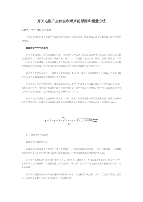
利用示波器可以看到纹波和噪声的波形,如图1所示。
纹波的频率与开关管频率相同,而噪声的频率是开关管的两倍。
纹波电压的峰峰值和噪声电压的峰峰值之和就是纹波和噪声电压,其单位是mVp-p。
图1 纹波和噪声的波形纹波和噪声的测量方法纹波和噪声电压是开关电源的主要性能参数之一,因此如何精准测量是一个十分重要问题。
目前测量纹波和噪声电压是利用宽频带示波器来测量的方法,它能精准地测出纹波和噪声电压值。
由于开关电源的品种繁多(有不同的拓扑、工作频率、输出功率、不同的技术要求等),但是各生产厂家都采用示波器测量法,仅测量装置上不完全相同,因此各厂对不同开关电源的测量都有自己的标准,即企业标准。
用示波器测量纹波和噪声的装置的框图如图2所示。
它由被测开关电源、负载、示波器及测量连线组成。
有的测量装置中还焊上电感或电容、电阻等元件。
图2 示波器测量框图从图2来看,似乎与其他测波形电路没有什么区别,但实际上要求不同。
GBZT229.4-2012工作场所职业病危害作业分级第4部分:噪声
GBZ/T 229.4-2012 工作场所职业病危害作业分级第 4 部分:噪声前言根据《中华人民共和国职业病防治法》制定本部分。
GBZ/T 229 《工作场所职业病危害作业分级》按部分发布,目前发布四个部分:——第 1 部分:生产性粉尘; ——第 2 部分:化学物;——第 3 部分:高温;——第 4 部分:噪声。
本部分是GBZ/T 229 的第 4 部分。
本部分是GBZ 2.2-2007《工作场所有害因素职业接触限值第2 部分:物理因素》中噪声接触限值的配套文件。
本部分由卫生部职业卫生标准专业委员会提出。
本部分主要起草单位:北京大学公共卫生学院、中国疾病预防控制中心职业卫生与中毒控制所、北京市化工职业病防治院、河南省新乡市职业病防治研究所。
本部分主要起草人:王生、李涛、孙伟、何丽华、张敏、周世义、杜燮祎。
1 范围工作场所职业病危害作业分级第4 部分:噪声GBZ/T 229 的本部分规定了工作场所生产性噪声作业的分级原则、分级方法。
本部分适用于各类存在生产性噪声作业的分级管理。
2 规范性引用文件下列文件对于本文件的应用是必不可少的。
凡是注日期的引用文件,仅注日期的版本适用于本文件。
凡是不注日期的引用文件,其最新版本(包括所有的修改单)适用于本文件。
GBZ 2.2-2007 工作场所有害因素职业接触限值第2 部分:物理因素GBZ/T 189.8-2007 工作场所物理因素测量第8 部分:噪声3 术语和定义下列术语和定义适用于本文件。
3.1 生产性噪声industrial noise在生产过程中产生的噪声。
3.2 稳态噪声steady noiseA 计权声级波动<3dB 的噪声。
3.3 非稳态噪声non-steady noiseA 计权声级波动≥3dB 的噪声。
3.4 脉冲噪声impulsive noise持续时间≤0.5s,间隔时问>1s,A 声级声压有效值变化≥40dB 的噪声。
3.5 噪声作业work(job)exposed to noise存在有损听力、有害健康或有其他危害的声音,且8h/d 或40h/周噪声暴露 A 等效声级≥80dB 的作业。
噪声的评价和测量

种 类
测声压
P50
2.3 噪声测量技术
2.3.1 噪声测量仪器
声级计
声级计工作原理
接收设备
中间设备
读出设备
01
03
02
04
05
06
2.3 噪声测量技术
2.3.1 噪声测量仪器
(1)声级计
噪声测量系统中的接收设备是传声器,也称话筒或麦克风,它是将声能转换成电能的元件。
(1)响度级
P60
2.1 噪声的评价
2.1.1 响度级和等响曲线 等响曲线
P61
2.1 噪声的评价
2.1.1 响度级和等响曲线
(3)响度
响度是用来描述声音大小的主观感觉量。响度的单位是宋(sone),定义1000Hz纯音声压级为40dB时的响度为1sone。 响度和响度级的关系可用下式表示:
P54
2.3.2 声强的测量
2.3 噪声测量技术
声强测量系统是通过两只相距很近且靠近声源表面的传声器和一套数据处理系统来测量声强,并可求得声源的声压级、声功率级。
声压传声器 加法器 减法器 积分器 乘法器
试述简单声级计的工作原理、结构和使用方法。
1
噪声测量中采用的传声器有哪些?目前采用最多的是哪种?为什么?
2.1 噪声的评价
(5)累积百分声级LN
对于随机起伏的噪声,如交通噪声,可用概率统计的方法来处理,即在一段时间T内进行随机采样,获得一组测量值,将它分级统计。
L10=86dB,L50=75dB,L90=55dB
P67
2.1.4 噪声基本评价量
2.1 噪声的评价
P74
2.1.4 噪声基本评价量 累积百分声级LN 交通噪声常采用统计声级LN作为评价量。 交通噪声指数TNI TNI=4(L10-L90)+L90-30
开关电源的纹波和噪声
开关电源的纹波和噪声开关电源(包括AC/DC转换器、DC/DC转换器、AC/DC模块和DC/DC模块)与线性电源相比较,最突出的优点是转换效率高,一般可达80%~85%,高的可达90%~97%;其次,开关电源采用高频变压器替代了笨重的工频变压器,不仅重量减轻,体积也减小了,因此应用范围越来越广。
但开关电源的缺点是由于其开关管工作于高频开关状态,输出的纹波和噪声电压较大,一般为输出电压的1%左右(低的为输出电压的0.5%左右),最好产品的纹波和噪声电压也有几十mV;而线性电源的调整管工作于线性状态,无纹波电压,输出的噪声电压也较小,其单位是μV。
本文简单地介绍开关电源产生纹波和噪声的原因和测量方法、测量装置、测量标准及减小纹波和噪声的措施。
纹波和噪声产生的原因开关电源输出的不是纯正的直流电压,里面有些交流成分,这就是纹波和噪声造成的。
纹波是输出直流电压的波动,与开关电源的开关动作有关。
每一个开、关过程,电能从输入端被“泵到”输出端,形成一个充电和放电的过程,从而造成输出电压的波动,波动频率与开关的频率相同。
纹波电压是纹波的波峰与波谷之间的峰峰值,其大小与开关电源的输入电容和输出电容的容量及品质有关。
噪声的产生原因有两种,一种是开关电源自身产生的;另一种是外界电磁场的干扰(EMI),它能通过辐射进入开关电源或者通过电源线输入开关电源。
开关电源自身产生的噪声是一种高频的脉冲串,由发生在开关导通与截止瞬间产生的尖脉冲所造成,也称为开关噪声。
噪声脉冲串的频率比开关频率高得多,噪声电压是其峰峰值。
噪声电压的振幅很大程度上与开关电源的拓扑、电路中的寄生状态及PCB的设计有关。
利用示波器可以看到纹波和噪声的波形,如图1所示。
纹波的频率与开关管频率相同,而噪声的频率是开关管的两倍。
纹波电压的峰峰值和噪声电压的峰峰值之和就是纹波和噪声电压,其单位是mVp-p。
图1 纹波和噪声的波形纹波和噪声的测量方法纹波和噪声电压是开关电源的主要性能参数之一,因此如何精准测量是一个十分重要问题。
- 1、下载文档前请自行甄别文档内容的完整性,平台不提供额外的编辑、内容补充、找答案等附加服务。
- 2、"仅部分预览"的文档,不可在线预览部分如存在完整性等问题,可反馈申请退款(可完整预览的文档不适用该条件!)。
- 3、如文档侵犯您的权益,请联系客服反馈,我们会尽快为您处理(人工客服工作时间:9:00-18:30)。
脉冲噪声的正确测量与评价方法
脉冲噪声是一种周期短、带宽宽、能量集中的噪声信号,它在许多领域中都有着很高的应用价值,如通信、军事、航空等。
正确测量和评价脉冲噪声是一项重要的任务,下面将介绍一些正确的测量和评价方法。
一、正确的测量方法
1.选用合适的测量设备。
测量脉冲噪声必须使用宽带、高分辨率的测试设备,如示波器等。
2.选择适当的测量点。
要确保测量点与信号源之间没有任何障碍物,以避免信号受到干扰。
3.使用合适的测量参数。
测量参数应根据噪声信号的特点来确定,如调整垂直灵敏度、水平扫描速度等。
4.测量时间应足够长。
脉冲噪声的特点是周期短、能量集中,因此要确保测量时间足够长,以获得稳定的测量结果。
二、正确的评价方法
1.功率谱密度法。
功率谱密度法是测量脉冲噪声的主要方法,它可以定量地评估信号的频谱特性。
通过功率谱密度的分析,可以准确地测量
噪声的频谱带宽和功率密度等参数。
2.指标评价法。
通过比较不同信号源的脉冲噪声,可以采用指标评价法来确定其信噪比、失真程度等参数。
具体方法是根据信号的失真程度、信噪比等评价指标,对各个信号源进行比较评价。
3.多项式拟合法。
多项式拟合法可以通过对噪声信号的时域特性进行多项式拟合,来评估信号的波形畸变程度。
具体方法是采用多项式来描
述噪声信号的时域特性,通过比较多项式拟合的参数来确定不同信号
源之间的波形畸变程度。
总之,脉冲噪声的正确测量与评价,需要选用合适的测量设备、选择
适当的测量点、和使用合适的测量参数等方法,只有这样才能获得准确、稳定的测量结果。
而且,评价方法也需要根据信号特点和实际需
求进行选择,才能得到合适的评价结果。