Part_5_Chapter_1_Provisions,_contingent_liabilities_and_contingent_assets_(IAS_37)
建筑施工门式钢管脚手架安全技术标准
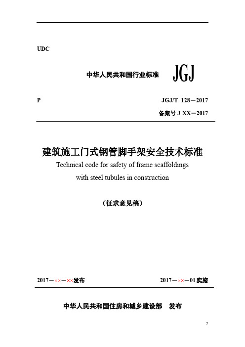
UDCJGJ中华人民共和国行业标准P JGJ/T 128-2017备案号J XX-2017建筑施工门式钢管脚手架安全技术标准Technical code for safety of frame scaffoldingswith steel tubules in construction(征求意见稿)2017-××-××发布2017-××-01实施中华人民共和国住房和城乡建设部发布中华人民共和国行业标准建筑施工门式钢管脚手架安全技术标准Technical code for safety of frame scaffoldingswith steel tubules in constructionJGJ/T 128-2017批准部门:中华人民共和国住房和城乡建设部施行日期: 2 0 × ×年×月 1 日中国建筑工业出版社2017 北京前言根据住房和城乡建设部《关于印发2016年工程建设标准、规范制订、修订计划的通知》(建标函[2015]274号)的要求,标准编制组经广泛调查研究,认真总结实践经验,参考有关国际标准和国外先进经验,并在广泛征求意见的基础上,编制了本标准。
本标准的主要技术内容是:1.总则;2.术语和符号;3.构配件;4.荷载;5.设计计算;6.构造要求;7.搭设与拆除;8.检查与验收;9.安全管理。
本标准修订的主要技术内容是:构配件技术要求;荷载分类及荷载组合计算;作业脚手架及支撑架设计计算;构造要求;搭设与拆除;检查与验收;安全管理。
本标准由住房和城乡建设部负责管理,由浙江宝业建设集团有限公司负责具体技术内容的解释。
各单位在执行过程中如有意见和建议,请寄送至浙江宝业建设集团有限公司(地址:浙江省绍兴市柯桥区杨汛桥镇杨汛路228号,邮政编码:312028)。
本标准主编单位:浙江宝业建设集团有限公司宝业湖北建工集团有限公司本标准参编单位:哈尔滨工业大学中国建筑业协会建筑安全分会北京城建集团有限责任公司上海市建工设计研究院有限公司长沙市住房和城乡建设委员会陕西省建设工程质量安全监督总站陕西建工集团有限公司湖南金峰金属构件有限公司中南大学浙江天工建设集团有限公司绍兴市滨海工业区管委会本标准主要起草人员:葛兴杰高林张有闻解金箭任占厚刘明生时炜陈杰刚施仁华杨棣柔杨建军王兰英孙炎云陶冶孙威裘国荣俞国方李鹏倪华君童晓刚黄德海本标准主要审查人员:目录1 总则 (1)2 术语和符号 (2)2.1 术语 (2)2.2 符号 (4)3 构配件 (9)4 荷载 (12)4.1 荷载分类 (12)4.2 荷载标准值 (12)4.3 荷载设计值 (17)4.4 荷载效应组合 (17)5 设计计算 (20)5.1 基本规定 (20)5.2 门式作业脚手架计算 (22)5.3 连墙件计算 (25)5.4 门式支撑架计算 (26)5.5 地基承载力验算 (30)5.6 悬挑脚手架支承结构计算 (31)6 构造要求 (34)6.1 一般规定 (34)6.2 门式作业脚手架 (35)6.3 悬挑脚手架 (38)6.4 门式支撑架 (41)6.5 地基 (45)7 搭设与拆除 (46)7.1 施工准备 (46)7.2 地基与基础 (46)7.3 搭设 (47)7.4 拆除 (48)8 检查与验收 (49)8.1 构配件检查与验收 (49)8.2 搭设检查与验收 (49)8.3 使用过程中检查 (52)8.4 拆除前检查 (52)9 安全管理 (69)附录A 门架、配件质量分类 (71)A.1 门架与配件质量类别及处理规定 (71)A.2 质量类别判定 (71)A.3 标志 (74)A.4 抽样检查 (74)附录B 计算用表 (75)本标准用词说明 (82)引用标准名录 (83)条文说明 (69)Contents1 General Provisions (1)2 Terms and Symbols (2)2.1 Terms (2)2.2 Symbols (4)3 Members And Accessories (9)4 Loads (12)4.1 Loads Classification (12)4.2 Normal Values of Loads (12)4.3 Design Values of Loads (17)4.4 Load Effect Combinations (17)5 Design Calculation (20)5.1 Basic Requirement (20)5.2 Calculation for Frame Operation Scaffold (22)5.3 Calculation for Tie Member (25)5.4 Calculation for Frame Shoring Scaffold (26)5.5 Calculation for Ground Bearing Capacity (30)5.6 Calculation of Supporting Structures for Cantilevered Scaffold (31)6 Detailing Requirements (34)6.1 General Requirements (34)6.2 Frame Operation Scaffold (35)6.3 Cantilevered Scaffold (38)6.4 Frame Shoring Scaffold (41)6.5 Foundation (45)7 Installation and Dismantlement (46)7.1 Construction Preparation (46)7.2 Subgrade and Foundation (46)7.3 Installation (47)7.4 Dismantlement (48)8 Check and Accept (49)8.1 Check and Accept for Members and Accessories (49)8.2 Check and Accept for Installation (49)8.3 Check in The Course of Use (52)8.4 Check before Dismantlement (52)9 Safety Management (54)Appendix A Quality Classification of Frame and Accessories (56)A.1 Quality Classifications and Treatment Specifications of Frames andAccessories (56)A.2 Criteria for Quality Classifications (56)A.3 Markers (59)A.4 Random Sampling Checks (59)Appendix B Tables for Calculation (60)Explanation of Wording in This Code (67)List of Quoted Standards (68)Addition:Explanation of Provisions (69)1 总则1.0.1 为规范门式钢管脚手架的设计、施工、使用与安全管理,做到技术先进、经济合理、安全适用,制定本标准。
RSPF系列产品说明书

ContentsDescription Page Introduction . . . . . . . . . . . . . . . . . . . . . . . . . . . . . .2Manual introduction . . . . . . . . . . . . . . . . . . . . . .2Product overview . . . . . . . . . . . . . . . . . . . . . . . .2Safety precautions . . . . . . . . . . . . . . . . . . . . . . .2RSPF series catalog number . . . . . . . . . . . . . . . . .3RSPF series product nameplate . . . . . . . . . . . . . .3Installation . . . . . . . . . . . . . . . . . . . . . . . . . . . . . . .4Pre-installation checklist . . . . . . . . . . . . . . . . . . .4Warning . . . . . . . . . . . . . . . . . . . . . . . . . . . . . . .4Mounting . . . . . . . . . . . . . . . . . . . . . . . . . . . . . .4Wiring diagrams . . . . . . . . . . . . . . . . . . . . . . . . .6Operation . . . . . . . . . . . . . . . . . . . . . . . . . . . . . . . .6Power up and system checkout . . . . . . . . . . . . .6Alarm silence pushbutton . . . . . . . . . . . . . . . . .6Specifications . . . . . . . . . . . . . . . . . . . . . . . . . . . .6Maintenance . . . . . . . . . . . . . . . . . . . . . . . . . . . . .7Liability . . . . . . . . . . . . . . . . . . . . . . . . . . . . . . . . .7Ordering guidelines . . . . . . . . . . . . . . . . . . . . . . . .8References . . . . . . . . . . . . . . . . . . . . . . . . . . . . . .8Warranty . . . . . . . . . . . . . . . . . . . . . . . . . . . . . . . .8Appendix A . . . . . . . . . . . . . . . . . . . . . . . . . . . . . .9PRL3 provision kit . . . . . . . . . . . . . . . . . . . . . . .9PRL4 provision kit 1 of 2 . . . . . . . . . . . . . . . . .10PRL4 provision kit 2 of 2 . . . . . . . . . . . . . . . . .11Installation instructions for Eaton RSPF seriessurge protective device (SPD)2Instruction Leaflet IL158004ENEffective September 2023Installation instructions for Eaton RSPF seriessurge protective device (SPD)EATON IntroductionManual introductionThis installation manual describes the installation and operation of the Eaton RSPF series surge protective device (SPD) . This technical document covers most aspects of installation and operation . This document is a guide only for licensed/qualifiedelectricians . If you require further information regarding a particular installation, application, or maintenance activity, please contact your Eaton representative . These instructions do not cover all details, variations or combinations of the equipment, its storage, delivery, installation, check-out, safe operation or maintenance . Care must be exercised to comply with local, state, and national regulations, as well as safety practices for this class of equipment .Please read and understand all installation and operating instructions prior to installation and use of this equipment.Product overviewThe Eaton RSPF series SPD protects critical electrical and electronic equipment from damage by voltage transients and surges when properly installed . This is done by shunting high-energy lightning surges (and other transient disturbances) away from the equipment being protected . It does this in nanoseconds by providing a low-impedance surge path to ground through thermally protected metal oxide varistors while supporting power frequency voltage . Proper installation is critical to ensure the SPD operates as intended .The Eaton RSPF series SPD was designed and developed to fit in the space of an Eaton F-/PD2-frame molded case circuit breaker for retrofit into existing panelboards or switchboards with space or provisions for an additional F-/PD2-frame molded case circuit breaker .This device features internal protection that will disconnect the surge protective component under fault conditions but will maintain power to the load, now unprotected from surge events .The Eaton RSPF series SPD is available in voltage ratings from 208 Vac to 600 Vac and surge current ratings of 50 kA and 100 kA . The enclosure measures 6 .00 x 4 .13 x 3 .81 inches (152 .4 x 104 .8 x 96 .7 mm) with a maximum weight of ~3 lb (~1 .36 kg) .The Eaton RSPF series is available in nine options . See Ordering guidelines on page 8 for more details .Safety precautions3Instruction Leaflet IL158004ENEffective September 2023Installation instructions for Eaton RSPF seriessurge protective device (SPD) EATON RSPF series catalog numberEach Eaton RSPF series SPD is identified by a catalog number, see example in T able 1 . The catalog number identifies the parameters that make up the unit .T able 1. Catalog numbering systemFor example, an RSPF series SPD with a catalog number of RSPF2403MA1A-K3, where:RSP = RSP series F = Surge frame 240 = Voltage code3 = Number of phases MA = Type and current rating of panel1 = Feature package A= ApplicationK3 = Optional panelboard provision kitSee Ordering guidelines on page 8 for additional voltages, features, and service options .RSPF series product nameplateEach Eaton RSPF series SPD has a product nameplate affixed to the front of the unit that identifies the catalog number and operating parameters . The catalog number consists of letters and numbers that identify the RSPF series, surge frame, voltage code, number of phases, panel bus rating, feature package, and application as shown in Figure 1 .Figure 1. RSPF series product nameplateRSP F 240 3 MA 1 A - K3Provision kit Application FeaturePanel busPhase VoltageFrameSeries4Instruction Leaflet IL158004ENEffective September 2023Installation instructions for Eaton RSPF seriessurge protective device (SPD)EATON InstallationPre-installation checklist•Does the panelboard have a 3-pole F-/PD2-frame breaker space available?•Does the panelboard have a panel with an opening that will allow the front of an RSPF series SPD to protrude through after installation?•Does the panelboard have 3-pole F-/PD2-frame phase connectors?If the answer is ‘Y es’ to all three previously listed statements, then the RSPF catalog number will NOT require an optional provision kit . If the answer is ‘No’ to any of the three previous statements, then an optional provision kit ‘- K3’ or ‘- K4’ will need to be included in the RSPF catalog number .1. Select a space to the mount the SPD as close to the incomingpower terminations as possible for optimum performance .2. Confirm that the system voltage is the same as the RSPF seriesSPD that you are installing .3. Check the facility grounding system . All grounding, bonding, andearthing must meet the NEC, CEC, and any other national, state, and local electrical codes .4. The installation consists of mounting and verifying the SPD’sconnections and torque settings on the line-side provision bus and the surge ground terminal .5. Check to ensure the area is clear of dirt, debris, or clutter thatmay hamper the installation .WarningMounting1. Locate the electrical system’s applicable block diagram inWiring diagrams section on page 6 .2. Turn OFF power to the electrical panel that the SPD is beingconnected to in accordance with NEC, CEC, state, county, and local codes for all safety ratings .3. Confirm no voltage is present before continuing .4. Remove the panelboard’s trim/door to assist with installation .5. Remove the four panel mounting screws where the SPD will bemounted . Then remove the black plastic fillers where the SPD will be located . If the existing panel has no openings and is being replaced with a new panel from a connector kit, then discard/recycle the old panel (see Figure 2) .Figure 2. Remove panel6. Remove any accessories that could impede the removalof the rails and panels, such as breaker padlockable handles and/or interlocks .7. Remove the four silver rail mounting screws located in the fourcorners shown in Figure 3 to remove the remaining panels andrails as one complete assembly .5Instruction Leaflet IL158004ENEffective September 2023Installation instructions for Eaton RSPF seriessurge protective device (SPD)EATON Figure 3. Remove panel and rails8. If installing a new PRL3 or PRL4 provision kit, do so nowfollowing the instructions provided (see Appendix A ) .9. View of a panelboard PRL3a with panels and rails removedshowing the phase connectors installed just above the F-/PD2-frame breaker (see Figure 4) .Figure 4. PRL3a with connector kit installed10. Place the RSPF SPD in the panelboard as close to the incomingpower terminations for optimum performance . Mount the RSPF to the bus using the hardware provided in the connector kit . Torque to 35 lb-in (3 .16 N·m) (see Figure 5) .Figure 5. SPD installed—terminal side11. The RSPF series SPD’s surge ground terminal can be wired toeither the ground bar or the neutral bar, whichever bar is closest to the SPD .a. When wiring to the ground bar, preferred method, usea green or green with yellow stripe #10 AWG insulatedconductor . Keep the wire length as short as possible . Torque the surge ground terminal screw to 35 lb-in (3 .16 N·m) (see Figure 6) .b. When wiring to the neutral bar, use a white #10 AWGinsulated conductor . Keep the wire length as short as possible . Torque the surge ground terminal screw to 35 lb-in (3 .16 N·m) .Figure 6. SPD installed—surge ground terminal12. After the SPD has been installed, check all mounting hardware,line terminal hardware, and the surge ground terminal for correct torque loading .13. Re-install the rails and panel assembly using the four silver railscrews . Torque the hardware according to the manufacturer’s specifications .14. Re-install any breaker interlocks or accessories .15.Mount the panel over the SPD .6Instruction Leaflet IL158004ENEffective September 2023Installation instructions for Eaton RSPF seriessurge protective device (SPD)EATON 16. Apply the “Protected by Eaton Surge Protective Device (SPD)Catalog No . RSPFxxxxxxxx” label to the left or right of the SPD (see Figure 7) .Figure 7. Apply label provided with SPD 17. Replace the panelboard’s trim/door .Wiring diagramsFigure 8. Surge ground terminal connected to the ground busFigure 9. Surge ground terminal connected to the neutral busOperationPower up and system checkoutSwitch main panel power to ON . The green LED should light to indicate the phase voltage is being monitored .If the red LED lights, remove power and contact the EatonCareTechnical Resource Center at 1-800-809-2772, option 5, sub-option 2, as the SPD may be damaged .If neither LED lights, remove power, check connections, and test again . Verify that the proper voltage is present . If the panel isenergized properly and the LEDs still do not light, contact EatonCare Technical Resource Center at 1-800-809-2772, option 5, sub-option 2, as the SPD may be damaged .Alarm silence pushbuttonThe RSPF SPD has an alarm silence pushbutton located below the red LED on the front of the SPD . The alarm will sound when the red LED indicates that the SPD has lost one or more phases of protection . To silence the alarm after loss of protection, press and hold the alarm silence pushbutton for at least 1 second . If the alarm silence pushbutton does not silence the alarm, contact EatonCare Technical Resource Center at 1-800-809-2772, option 5, sub-option 2, as the SPD may be damaged .SpecificationsT able 2. SpecificationsDescriptionSpecificationkA per phase50 (on units with filtering), 100Nominal discharge current (I n )20 kASystem voltages240 = 120/208Y, 127/220Y, 240D480 = 220/380Y, 230/400Y, 240/415Y, 277/480Y, 480D600 = 347/600Y, 600D Short-circuit current rating 200 kA Input power frequency 50/60 Hz Protection modesWye L–N, L–L Delta L–G, L–LOperating temperature –40 °F to +140 °F (–40 °C to +60 °C)Relative humidity 5%–95%, noncondensing Maximum altitude 6561 ft (2000 m)Weight~3 lb (~1.36 kg)Certification/listingUL T 1449 5th Edition, CSA T 269.1-17269.2-17, C22.2 No. 8-13 EMI Filter Tested to UL 1283 6th EditionSPD typeUL 1449 5th Edition and CSA type 1 and type 2 SPD RoHS compliant YesEnclosureIndoor use only Designed and tested in accordance with the most recent version of these standards:IEEE T C62.41.1IEEE C62.41.2IEEE C62.43IEEE C62.45IEEE C62.48IEEE C62.627Instruction Leaflet IL158004ENEffective September 2023Installation instructions for Eaton RSPF seriessurge protective device (SPD) EATON MaintenanceThe RSPF series SPD is a self-contained device that requires no maintenance and contains no serviceable parts . If the red LED is illuminated, the unit has lost one or more modes of surge protection and must be replaced . Please contact your localauthorized distributor or EatonCare Technical Resource Center at 1-800-809-2772, option 5, sub-option 2 for additional information and technical assistance, as the SPD may be under warranty .LiabilityThis instruction leaflet is published solely for information purposes and should not be considered all-inclusive . If further information is required, you should consult EatonCare Technical Resource Center at 1-800-809-2772, option 5, sub-option 2 . Sale of the productshown in this literature is subject to terms and conditions outlined in appropriate Eaton selling policies or other contractual agreements between the parties . This literature is not intended to and does not enlarge or add to any such contract . The sole source governing the rights and remedies of any purchaser of this equipment is thecontract between the purchaser and Eaton .In no event will Eaton be responsible to the purchaser or user in contract, in tort (including negligence), strict liability or otherwise for any special, indirect, incidental or consequential damage, or loss whatsoever, including but not limited to damage or loss of equipment use, plant or power system, cost of capital, loss of power, additional expenses in the use of existing power facilities or claims against the purchaser or user by its customers resulting from the use of the information, recommendations, and description contained herein .8Instruction Leaflet IL158004ENEffective September 2023Installation instructions for Eaton RSPF seriessurge protective device (SPD)EATON Ordering guidelinesT able 3. RSP catalog numbering systema Omit if provision kit is not needed.ReferencesProvision kits contain phase connectors, deadfront cover, filler covers, hardware, and instruction sheet . Contact the EatonCare Technical Resource Center at 1-800-809-2772, option 5,sub-option 2, to order the appropriate connector kit listed below for the intended installation .The following references are available at www .eaton .com .• Current Eaton panelboards—Renewal parts RP01400001E •Eaton renewal parts data—Panelboard renewal parts supplement RP01414001E•Vintage Cutler-Hammer panelboards and switchboards— Renewal parts RP01400003E•Vintage Westinghouse panelboards —Renewal parts RP01400002EWarrantyEaton warrants the RSPF series SPD to be free from defects in both workmanship and materials for a period of 2 years from shipment . To register the product, go to www .eaton .com/RSP and click on the warranty registration icon .Eaton assumes no risk or liability for results of the use of the product purchased, including but not limiting the generality of the foregoing:(1) The use in combination with any electrical or electroniccomponents, circuits, systems, assemblies, or any other materials or substances .(2) Unsuitability of any product for use in any circuit or assembly .Purchaser’s rights under the warranty shall consist solely of requiring Eaton to repair, or at Eaton’s sole discretion, replace, free of charge, F .O .B . factory, any defective items received at said factory within said term determined by Eaton to be defective . The giving of or failure to give any advice or recommendations by Eaton shall not constitute any warranty by or impose any liability upon Eaton AND IS IN LIEU OF ANY AND ALL OTHER WARRANTIES EXPRESSED, IMPLIED OR STATUTORY AS TO THE MERCHANTABILITY , FITNESS FOR PURPOSE SOLD, PRODUCTIVENESS, OR ANY OTHER MATTER . In no event shall Eaton be liable for special or consequential damages or for delay in performance of the warranty .This warranty does not apply if the unit has been misused, abused, altered, tampered with, or applied in excess of the specifications other than those written on the nameplate . At the end of thewarranty period, Eaton shall be under no further warranty obligation expressed or implied .The Eaton RSPF series SPD covered by this warranty certificate can only be repaired or replaced by the factory . A RETURN MATERIAL AUTHORIZATION (RMA) number must be obtained . Please enter a Vista warranty claim or contact CORE (Center of Returns Excellence) at 1-800-410-2910 for help with entering a claim or to obtain an update on your claim status . Repair or replacement will be returned collect . If it is determined that the returned product contains manufacturer’s defects, then Eaton will replace the defective product at Eaton’s expense (including shipping charge) .RSP F 240 3 MA 1 A – K3SeriesRSP = RSP series Surge frameF = F framePhase3 = 3-phaseApplicationA = Direct BUS mountedVoltage code options240 = 120/208Y, 127/220Y, 240D 480 = 220/380Y, 230/400Y, 240/415Y, 277/480Y, 480D 600 = 347/600Y, 600DType and current rating of panel optionsMA = Main service up to 2000 A, 100 kA per phase SA = Sub-panel up to 800 A, 50 kA per phaseSB = Sub-panel greater than 800 A, 100 kA per phaseFeature package options1 = Basic (available with SB and MA )2 = Basic plus filtering (available with SA only)Provision kit aK3 = Provision kit for PRL3A panelboard K4 = Provision kit for PRL4A panelboard9Instruction Leaflet IL158004ENEffective September 2023Installation instructions for Eaton RSPF seriessurge protective device (SPD) EATON Appendix APRL3 provision kit10Instruction Leaflet IL158004ENEffective September 2023Installation instructions for Eaton RSPF seriessurge protective device (SPD)EATON PRL4 provision kit 1 of 211Instruction Leaflet IL158004EN Effective September 2023Installation instructions for Eaton RSPF seriesEATON Eaton1000 Eaton Boulevard Cleveland, OH 44122 United StatesEaton .com© 2023 EatonAll Rights ReservedPrinted in USAPublication No . IL158004EN / Z27895 September 2023Eaton is a registered trademark.All other trademarks are propertyof their respective owners.Installation instructionsfor Eaton RSPF series surge protective device (SPD)Instruction Leaflet IL158004ENEffective September 2023For additional information, please call:Eaton’s Power Quality Technical Support1-800-809-2772, option 5, sub-option 2.。
《建筑工程交通设计及停车库(场)设置标准》(DG TJ 08-7-2014) (1)

DB11_T825-2015绿色建筑评价标准
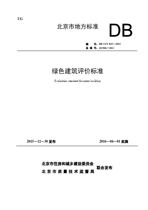
Contents
1 General Provisions ...........................................................................................................................1 2 Terms ................................................................................................................................................2 3 Basic Requirements .........................................................................................................................3
3.1 一般规定 ............................................................................................................................... 3 3.2 评价与等级划分.................................................................................................................... 3 4 节地与室外环境 ....................................................................
气泡混合轻质土使用规程

目次1总则 (3)2术语和符号 (4)2.1 术语 (4)2.2 符号 (5)3材料及性能 (6)3.1 原材料 (6)3.2 性能 (6)4设计 (8)4.1 一般规定 (8)4.2 性能设计 (8)4.3 结构设计 (9)4.4 附属工程设计 (10)4.5 设计计算 (10)5配合比 (13)5.1 一般规定 (13)5.2 配合比计算 (13)5.3 配合比试配 (14)5.4 配合比调整 (14)6工程施工 (15)6.1 浇筑准备 (15)6.2 浇筑 (15)6.3 附属工程施工 (15)6.4 养护 (16)7质量检验与验收 (17)7.1 一般规定 (17)7.2 质量检验 (17)7.3 质量验收 (18)附录A 发泡剂性能试验 (20)附录B 湿容重试验 (22)附录C 适应性试验 (22)附录D 流动度试验 (24)附录E 干容重、饱水容重试验 (25)附录F 抗压强度、饱水抗压强度试验 (27)附录G 工程质量检验验收用表 (28)本规程用词说明 (35)引用标准名录 (36)条文说明 (37)Contents1.General provisions (3)2.Terms and symbols (4)2.1 Terms (4)2.2 Symbols (5)3. Materials and properties (6)3.1 Materials (6)3.2 properties (6)4. Design (8)4.1 General provisions (8)4.2 Performance design (8)4.3 Structure design (9)4.4 Subsidiary engineering design (9)4.5 Design calculation (10)5. Mix proportion (13)5.1 General provisions (13)5.2 Mix proportion calculation (13)5.3 Mix proportion trial mix (14)5.4 Mix proportion adjustment (14)6. Engineering construction (15)6.1 Construction preparation (15)6.2 Pouring .............................................................. .. (15)6.3 Subsidiary engineering construction (16)6.4 Maintenance (17)7 Quality inspection and acceptance (18)7.1 General provisions (18)7.2 Quality evaluate (18)7.3 Quality acceptance (19)Appendix A Test of foaming agent performance (20)Appendix B Wet density test (22)Appendix C Adaptability test (23)Appendix D Flow value test.................................................................................. .. (24)Appendix E Air-dry density and saturated density test (25)Appendix F Compressive strength and saturated compressive strength test (27)Appendix G Table of evaluate and acceptance for quality (28)Explanation of Wording in this code (35)Normative standard (36)Descriptive provision (37)1总则1.0.1为规范气泡混合轻质土的设计、施工,统一质量检验标准,保证气泡混合轻质土填筑工程安全适用、技术先进、经济合理,制订本规程。
Chemical and isotopic systematics of oceanic

From SAUNDERS , eds) , 1989 , Magmatism in the Ocean Geological Socicty Special Publication No. 42 , pp. 313-345.
3 13
3 14
Major issues in the chemical evolution and geodynamics of the mantle
A first-order aim in the study of oceanic basa Its is to improve our understanding of the chemical
S.-s. Sun & W. F. McDonough
contribute to the geochemica\ and isotopic evolution of mantle reservoirs. The nature of mantle convection processes through time (whole mantle or layered mantle) is critical to our understanding of the chemica\ and thermal evo\ution of the Earth. The term ‘ reservoir' is used here in a general sense to refer to a part of the man tI e which has a partícular regíonal chemical and isotopic composítion , whereas the term ‘ componen t' speci缸" ally refers to a reservoir (or many reservoìrs) in thεmantle with an isotopically distinctive composition (eg HIMU , EM , MORB). This use of theterm ‘compone时, is similar to that in Zindler & Hart (1986). In essεnce each mantle reservoir carries an identifiable chemistry and isotopic fingerprínt of the specific processes and environments whích hav已 acted upon it. These composítional fingerprints reflect the responses to such factors as partìal melting under di在'erent P-T-X(C0 2 , water rich , melts or fluids) conditions , sediment subduction , and recycling of oceanic crust and asthenosphere through the subduction zone environment. Mantle differentiation processes through time Our understandin喜 of mantle differentiation 蹈' sociated with the Earth's accretion , core formation and the e挂rly history of man tI e-crust fractionation relies upon chemical and isotopíc studies of Archaean to modern volcanic rocks and other planetary bodies , petrological and chemical experiments carried out under hightemperature and high-prεssure conditions , and numerical modelling of the thermal evolution of the Earth. Even if some thermal models favour the pr出 ence of upper and lower mantle convection cells at present (eg Richter 1985) , there is no obvious reason to argue against whole-mantle convectÌon during the early history of the Earth. It is generaIl y assumed that the early Earth's man tI e temperature was higher (eg 2000 oC surface potential temperature) (Richter 1985) , which would favour vigorous , and probably chaotic , whole-mantle convection with possible largescale mantle meIting. Consequent1 y , it is very likely that the lower mantle would have been ìnvolved in the formation of the earliest enriched lithosphere , resulting in an incompatibleelement-dεpleted character , ie a non-primitive fractionated Iower mantle. At the same time , dense early-formed severely hydrothermaIl y altered mafic to ultramafic crust and lithospheric mantle may well have been rapidly recycI ed back i 挝o the convective mantle by meteorite
HP ArcSight Management Center Appliance 安装与使用指南说明书

Getting Started with HP ArcSight Management Center ApplianceThe HP ArcSight Management Center Appliance package includes detailed rack installation instructions, which you can use to rack-mount your appliance. After rack-mounting, you can set up your Appliance for first use.This document explains how to configure an IP address on the Appliance, install a license file, and connect to it the first time.Follow these basic steps to install and start using your Appliance:Prepare to Install the ArcSight Management Center AppliancePrior to installation of the ArcSight Management Center Appliance, do each of the following:1Redeem your Management Appliance license key by following the instructions in the enclosed “Hewlett-Packard Entitlement Certificate” document. You will need this key to access Management Appliance functionality.2Apply for an account on Protect 724 ( ), the ArcSight user community. You will need this account to access product documentation and other community-based resources for Management Appliance.1Prepare to Install the ArcSight Management Center Appliance 2Install the ArcSight Management Center Appliance 3Configure a New IP Address 4Accept the End User License Agreement and Log In 5Initialize the ArcSight Management Center Appliance 6Get the Management Appliance Documentation 7Set Up the Management Appliance for Remote AccessInstall the ArcSight Management Center ApplianceTo install the ArcSight Management Center Appliance:1Unpack the appliance and its accompanying accessories.2Follow the rack installation instructions to securely mount it.3Make the rear panel connections.4Power on the appliance.Configure a New IP AddressArcSight Management Center Appliance ships with the default IP address 192.168.35.35 (subnet mask 255.255.255.0) on Eth0. To begin setting up your appliance, use the ArcSight Management Center Appliance Command Line Interface (CLI) to configure a new IP address.To run a command in the CLI, type it at the prompt and then press Enter .To set up a new IP address for Management Appliance:1Select one of the following methods to connect to the Management Appliance CLI:◆Log into iLO and launch the remote console feature. For more information, see “Set Up the Management Appliance for Remote Access” on page 4.◆Connect a keyboard and monitor to the ports on the rear panel of the Appliance.◆Connect a terminal to the serial port on the Appliance using a null modem cablewith DB-9 connector . The serial port requires a standard VT100-compatibleterminal: 9600 bps, 8-bits, no parity, 1 stop bit (8N1), no flow control.2In the CLI, enter the following default credentials to log in as the administrator:Login: adminPassword: password3Enter the IP address in one of the following formats:◆set ip eth0 <ip>/<prefix>(For example, set ip eth0 192.0.2.5/24)◆set ip eth0 <ip> <subnetmask>(For example, set ip eth0 192.0.2.5 255.255.255.0)4Enter set defaultgw <ip>, replacing <ip> with your default gateway IP address. 5Enter set hostname <domain_name>.<>, replacing with the fully-qualified domain name (FQDN) of thedesired host.Read carefully through the instructions, cautions, and warnings that areincluded with the appliance shipment. Failing to do so can result in bodily injury or appliance malfunction.6Enter set dns <search_domain_name1>,<search_domain_name2>,…<nameserver1> <nameserver2>, replacing each <search_domain_nameN> witha search domain, and each <nameserverN> with the IP address of a name server. (Forexample, set dns ,192.0.2.1 192.0.2.2).7Enter set ntp <ntp_server> <ntp_server> <ntp_server>, replacing <ntp_server> with the NTP server you want to use to set the time. (For example,Management Appliance> set ntp )8To confirm that the settings are correct for your environment, enter show config.For more information on the Command Line Interface, refer to the HP ArcSightManagement Center Appliance Administrator’s Guide, or enter help at the prompt for a listof available commands.Accept the End User License Agreement and Log In The first time you connect to the ArcSight Management Center Appliance through abrowser, you are directed to the End User License Agreement. Before you can log in andinitialize the appliance, you must review and accept the license agreement.To accept the license agreement and start initializing ArcSight Management CenterAppliance:1Use the following URL to connect to ArcSight Management Center Appliance through a supported browser: https://<IP address>, where <IP address> is the new IPaddress you just configured.Scroll down to the bottom of the screen to review the license. Mark the “I accept theterms of the License Agreement” check box and click Accept.The Login screen is displayed.2Use the following default credentials to log in as the administrator:Username: adminPassword: passwordFor security reasons, be sure to change the default credentials as soon as possible afterconnecting to Appliance for the first time. Refer to the HP ArcSight Management CenterAppliance Administrator’s Guide for instructions.Initialize the ArcSight Management Center ApplianceAfter logging in for the first time, the ArcSight Management Center Appliance Configurationpage appears. In the License field, you can browse for and upload your current license.Once the license is successfully loaded, click Save to save it. Optionally, you may also setyour date and time settings. Once these steps are completed, your Appliance is ready foruse.For instructions on how to operate the ArcSight Management Center Appliance andconfigure it to suit your needs, see the HP ArcSight ArcSight Management CenterAdministrator's Guide. You should also refer to the release notes for any late-breakinginformation.Confidential4Get the Management Appliance DocumentationThe Release Notes and HP ArcSight Management Center Appliance Administrator’s Guide for your Appliance are available for download from the ArcSight Protect 724 Community at https:// .Online Help for ArcSight Management Center Appliance is available through the user interface (UI). The help provides the same information contained in the Administrator's Guide in a contextual format. To access the help, click the help icon in the top right corner of any ArcSight Management Center Appliance UI page.Set Up the Management Appliance for Remote AccessHP ArcSight strongly recommends setting up and configuring your appliance for out-of-band remote access. Doing so ensures that you (as well as HP Customer Support, with your permission and assistance) can remotely access your appliance's console for troubleshooting, maintenance, and power control.All ArcSight Management Center Appliances are equipped with an HP ProLiant Integrated Lights-Out (iLO) Advanced remote management card. Follow the directions in the HP ProLiant Integrated Lights-Out User Guide to set up your appliance for remote access. The guide is available at /go/iLO .Contact InformationCopyright © 2014 Hewlett-Packard Development Company, L.P .Confidential computer software. Valid license from HP required for possession, use or copying. Consistent with FAR 12.211 and 12.212, Commercial Computer Software, Computer Software Documentation, and Technical Data for Commercial Items are licensed to the U.S. Government under vendor's standard commercial license.The information contained herein is subject to change without notice. The only warranties for HP products and services are set forth in the express warranty statements accompanying such products and services. Nothing herein should be construed as constituting an additional warranty. HP shall not be liable for technical or editorial errors or omissions contained herein.Follow this link to see a complete statement of copyrights and acknowledgements: /copyrightPhone A list of phone numbers is available on the HP ArcSight TechnicalSupport page: /us/en/software-solutions/software.html?compURI=1345981#.URitMaVwpWI .Support Web Site Protect 724 Community https://。
HG∕T 20538-2016 衬塑钢管和管件选用系列

中华人民共和国工业和信息化部
公
主七
t=I
2016 年第 3 号
工业和信息化部批准《往复真空泵》等 643 项行业标准(标准编
号、名称、主要内容及起始实施日期见附件) ,其中机械行业标准 214 项、汽车行业标准 7 项、航空行业标准 1 项、轻工行业标准 59 项、化工
行业标准 110 项、冶金行业标准 21 项、建材行业标准 6 项、石化行业
本标准共分 8 章,主要内容包括:总则,术语,基本要求,衬塑钢管和管件尺寸系列,技术要求,检 验和试验,标记,包装、运输和储存。
本标准与 HG 20538-1992 、 HG/T 21562-1994 相比,主要变化如下: 1.本标准将原行业标准《衬塑 cpp 、 PE 、 PVC) 钢管和管件 ))HG 20538-1992 及原行业标准《衬聚
基本要求…........…………….......………...............…........…..............…........…................…·……( 3 )
3
3.1 3.2
衬塑钢管和管件的设计选用
…..
买方设计文件与供货方预制文件的要求
4
衬塑钢管和管件尺寸系列..,
四氟乙烯钢管和管件 ))HG/T 21562-1994 合并为一个标准,标准名称改为《衬塑钢管和管件选用系 列》。对其章节进行全面修订,增加了前言、术语、基本要求、制造、包装、运输、储存、用词说明、条文
说明等。增加了内衬材料和内衬管件型式的种类,扩大了管道规格尺寸范围。取消了螺纹法兰、铸 钢管件及涂塑衬塑等内容。对相关的技术要求和检验要求进行了修改。
…………………………………………………………………………………………………(1 0) ………………………………………………………………………………………………(1 2) …………………………………………………………………………………………(1 4)
- 1、下载文档前请自行甄别文档内容的完整性,平台不提供额外的编辑、内容补充、找答案等附加服务。
- 2、"仅部分预览"的文档,不可在线预览部分如存在完整性等问题,可反馈申请退款(可完整预览的文档不适用该条件!)。
- 3、如文档侵犯您的权益,请联系客服反馈,我们会尽快为您处理(人工客服工作时间:9:00-18:30)。
Advanced accounting and international financial statements – Part 5 Ch 1 Pag. 6
Definitions and recognition
• A contingent asset is a possible asset that arises from past events and whose existence will be confirmed only by the occurrence or non-occurrence of one or more uncertain future events not wholly within the control of the enterprise.
– Future operating losses – Onerous contracts – Restructuring plans
• Related interpretations
Advanced accounting and international financial statements – Part 5 Ch 1 Pag. 2
Objective and scope
• Objective
– Ensure appropriate recognition criteria and measurement bases for provisions, contingent liabilities and contingent assets – Ensure that sufficient information is disclosed to enable users to understand nature, timing and amount
– Economic outflow is probable
– More likely than not
– Reliable estimate can be made
– Rebuttable presumption
Advanced accounting and international financial statements – Part 5 Ch 1 Pag. 5
Definitions and recognition
• A liability is a present obligation of the enterprise arising from past events, the settlement of which is expected to result in an outflow from the enterprise of resources embodying economic benefits. • A provision is a liability with uncertain timing and/or amount.
• Scope
– Accounting for provisions, contingent liabilities and contingent assets, except those that result from
– Executory contracts (unless onerous)
– Contracts under which neither party has performed any of its obligations or both parties have partially performed their obligations
– Scope of business – Manner of conducting business
– Recognize provision when the recognition criteria are met
Advanced accounting and international financial statements – Part 5 Ch 1 Pag. 10
Specific applications
• Operating losses
– Do not recognize provisions for future operating losses – Expected operating losses may indicate impairment
• Recognize onerous contract obligations as a provision
– Is a possible obligation as a result of a past event, that may, but probably not, require an outflow of resources – Should be disclosed unless the possibility of outflow is remote
– The amount that an entity would rationally pay to settle the obligation at the end of the reporting period or to transfer it to a third party
Advanced accounting and international financial statements – Part 5 Ch 1 Pag. 8
– Those dealt within another IFRS (IFRS 3, IAS 11, IAS 12, IAS 17, IAS 19, IFRS 4, IAS 18 , IAS 32/39)
Advanced accounting and international financial statements – Part 5 Ch 1 Pag. 3
– a valid expectation to carry out this plan
– Announcement of main features – Start of implementation – Binding sale agreement when restructuring involves sale of an operation
– Legal obligation (contract, law,…) – Constructive obligation
– entity has indicated acceptance of responsibility (e.g. by established pattern, published policies, specific statement) and as a result created valid expectation of discharge
Part 5: Chapter 1 - Provisions, contingent liabilities and contingent assets (IAS 37)
Overview
• • • • Objective and scope Definitions and recognition Measurement Specific applications
Defቤተ መጻሕፍቲ ባይዱnitions and recognition
• A contingent liability
– Is a present obligation as a result of a past event:
– That probably requires an outflow of economic benefits, but the obligation cannot be measured
Advanced accounting and international financial statements – Part 5 Ch 1 Pag. 9
Specific applications
• Restructuring plan
– Program planned & controlled by management that materially changes either:
Advanced accounting and international financial statements – Part 5 Ch 1 Pag. 7
Measurement
• The provision should be measured at the best estimate of the expenditure required to settle the present obligation at the end of the reporting period
Advanced accounting and international financial statements – Part 5 Ch 1 Pag. 4
