PLC电梯控制英文文献
基于PLC的电梯控制系统设计中英文翻译
Elevator System Based on PLCComposed by the order of relay control system is a realization of the first elevator control method. However, to enter the nineties, with the development of science and technology and the widespread application of computer technology, the safety of elevators, reliability of the increasingly high demand on the relay control weaknesses are becoming evident.Elevator control system relays the failure rate high, greatly reduces the reliability and safety of elevators, and escalators stopped often to take with the staff about the inconvenience and fear. And the event rather than taking the lift or squat at the end of the lift will not only cause damage to mechanical components, but also personal accident may occur.Programmable Logic Controller (PLC) is the first order logic control in accordance with the needs of developed specifically for industrial environment applications to operate the electronic digital computing device. Given its advantages, at present, the relay control the lift has been gradually replaced by PLC control. At the same time, AC variable frequency motor speed control technology, the way the lift drag speed has been a gradual transition form DC to AC frequency converter. Thus, PLC control technology increases VVVF Elevator modern technology has become a hot industry.1. PLC elevator control advantages:(1) Used in elevator control PLC, with so ware for automatic control of lift operation, reliability greatly increased.(2) Layer was removed and majority of the relay, the control system structure is simple, simplify the external circuit.(3) PLC can be a variety of complex control system, easy to add or change control functions.(4) PLC can be automated fault detection and alarm display to improve the operation of security and ease of maintenance.(5) For the group control the allocation and management, and improve the efficiency of elevator operation.(6)Do not need to change the control scheme changes when the hardware connection.2. VVVF elevator control characteristics.With the power electronics, microelectronics and computer technology to control the rapid development of technology, communication technology VVVF also a very rapid rate. AC variable frequency motor speed control technology is the power to improve the process in order to improve product quality and improving the environment and promoting technological progress as a primary means. Frequency of its excellent performance and the speed brake from a smooth performance, high efficiency, high power factor and power-saving of a broad scope of application and many other advantages of being at home and abroad recognized as the most promising approach speed.Exchange characteristics of VVVF Elevator:(1) low energy consumption.(2) low load circuit, the re emergency power supply device of small.In the acceleration stage, the required start-up current of less than 2.5 times the rated current. Peak starting current and time is short. Since the starting current is drastically reduced, so power consumption and power supply cable diameter can be reduced a lot. Required for emergency power supply devices are also relatively small size.(3) high reliability and long service life.(4) good comfort.Elevator operation is best to follow the speed curve of a given operation. Their characteristics can be adapted to human feelings, and to ensure that noise operation, smooth brake Ping layer and high precision.(5) stable noise-free.(6) In the car, the engine room and adjacent areas to ensure that noise. Because their systems use a high clock frequency. Always produce a true sine wave power supply current yet. Motor torque ripple does not appear. Therefore, to eliminate vibration and noise.3. Elevator control technology.The so-called elevator control technology refers to the elevator drive system and electrical control system of automatic control. 70 as the 20th century in China’s elevator were marked by the exchange of two-speed elevator. Its speed is used to change the elevator traction motor of the very few, two or mute-level approach to the number of windings, very few of them as high-speed winding of the winding, a very few number of windings as the low-speed winding. Windings for high-speed elevator-speed start-up and running, low-speed windings for braking and the maintenance of elevators.The early 80s, VVVF inverter controlled variable lift system available. It uses AC motor drivers, are able to reach the level of DC motor, control the speed of the current has reached 6 m/sec. Its small size, light weight, high efficiency, energy saving, inc1uding the past almost all the advantages of the lift. Is the latest elevator drive systemOperation in vertical lift, there is also the starting point of the terminus station. For more than three-story elevator buildings, the starting point of the terminal stations and stops between the had not, the starting point for these stations at the first floor of the terminal located at the highest floor. Starting point in the first floor of the station known as base stations, known as the starting point at both ends of the terminal stations and stations at both ends of intermediate stops between stations.Outside the station has a call box, box set are used by staff for elevator call button or touch the call button, the general ends of the lift stations in the call box on the Settings button or touch of a button. 1iddle layer of the station set up the call box button or touch button 2. No drivers for the control of elevators, at various stations are set up calls me on a button or touch button. Elevator car and the internal settings (except for debris elevator) to manipulate me. Control box switch on the handle or set up stations and the corresponding layer of buttons or touch-button control box on the touch-control button or command button or touch the city button. Outside the command button or touch-button issue as the signal outside the command signal, within the commandbutton or touch-button issue within the signal as a command signal. 80 In the mid-20th century, the touch button has been replaced by micro-button.As the elevator call box outside the base station, in addition to set up a call button or touch button, but a1so set a key switch in order to work the elevator clearance. Drivers or management staff to open the elevator to the base station can wriggle through a dedicated key to the key switch. Close the elevator in place to autocratically cut off the elevator control power supply or power supply.4. PLC Control Elevator Design.With the continuous development of urban construction, the increasing high-rise buildings, elevators and life in the national economy has a broad application. Elevator high-rise buildings as a means of transport in the vertical run of daily life have been inextricably linked with people. In fact the lift is based on external call control signals, as well as the laws of their own, such as running, and the cal1 is random, the lift is actually a man-machine interactive control system, simple to use control or logic control order can not meet the control requirement, and therefore, elevator control system uses a random control logic. Elevator control is current1y generally used in two ways, first, the use of computer as a signal control unit, the completion of the lift signal acquisition, operation and function of the se, to achieve the lift and set the autocratic scheduling function to run the election, drag the control from inverter to complete; the second control mode with programmable logic controller (PLC) to replace the computer control signal sets the election. From the control and performance, these two types of methods and there is no significant difference. Most of the domestic manufacturers to choose the second approach, because the smaller scale of production there design and manufacture of high cost of computer control devices; and PLC high reliabi1ity, convenient and flexible program design, anti-interference ability, stable and reliable operation of the characteristics of Therefore, the elevator control system is now widely used to realize programmable control.5. Lift control system.Lift control system is used to manipulate each control process by managing such commands as running direction, car call, landing call, load signal, landing indication, safety protection.Lifts in different applications have different load, speed and drive / control modes. Lifts in same application may also have different control mode. Whatever control mode is adopted, the objective is the same, to be specific, according to car call and landing call, lift control system will execute automatic logic judgment to determine which lift will receive signal, which direction lift will run towards and complete programmed control objective through electrical automatic system based on command.Types of lift control system.Control system development chronicle indicates that there has appeared many control modes, such as such as relay control, PLC, single computer control, multiple-computer control. Prevailing in different era, these control modes are still employed in lifts now due to massive integrated circuit and computer technology development.PLC control system.As abbreviation of programmable logic controller, PLC is an electronic system featuring digital computation. It adopts programmable EPROM to execute logic computation, order control, timing, number counting, arithmetic computation, besides, it can input and output through digital or analogy modes.The mechanism of PLC control is as follows: input of PLC includes such command signals, as power key to home landing, car call, landing call, various safety switches, position signal, while output of PLC includes contactor, relay, indicators of car / landings and communication unitary, indicators inside car and switch, position signal, are input to PC, while other executing com.Programming principle is determined by lift control mode. Programming can either be made according to relay logic control circuit or individually in different phases according to lift control functions after completely separating from relay control circuit. Based on the ready made control circuit, the formeris simple and easy to master, while the latter involves less programs by integrating programs of small function.Used in lift control system, PLC has such advantages, as high reliability, stability, easy programming, user-friendliness, convenient maintenance & inspection.Nowadays, there is a wide range and series of programmable logic controllers. Input / output points range from 30 to 8000 or above, so as to meet lift control requirements with different landing number.PLC 控制下的电梯系统由继电器组成的顺序控制系统是最早的一种实现电梯控制的方法。
基于plc电梯控制外文文献翻译、中英文翻译、外文翻译
In the article has analyzed the elevator loadcharacteristics, elaborated uses the trapezoid acceleration curve theelevator ideal velocity curve, unifies the frequency changer and thePLC performance, elaborated the elevator control system constitutionand the operational factor. Elaborated the elevator speed curveproduces the method, has induced the characteristic which designs byPLC constitution control system software.Key word: Load characteristics ideal velocity curve control systemsoftware design1. OutlineAlong with the urban construction unceasing development, thehigh-rise construction unceasingly increases, the elevator has thewidespread application in the national economy and the life. Theelevator took in the high-rise construction the vertical movementtransportation vehicle already and people's daily life is inseparable.In fact the elevator is according to exterior movement and so oncalling signal as well as own control rule, but calls is stochastic,the elevator is a person machine interactive control system in fact,purely is cannot satisfy the control request with the sequentialcontrol or the logical control, Therefore, the elevator control system uses the stochastic logical waycontrol. At present the elevator control generally has selected twomethods, one is uses the microcomputer to take the signal controlunit, completes the elevator signal gathering, the running status andthe function hypothesis, realizes the elevator automatic dispatch andthe collection chooses the movement function, drives the control tocomplete by the frequency changer; The second control mode (PLC)substitutes for the microcomputer realization signal collection withthe programmable controller to choose the control. Said from the control mode and the performance, these two methodscertainly not too big difference. The domestic factory mostly choosesthe second way, its reason lies in the production scale slightly, owndesign and the manufacture microcomputer control device cost ishigher; But PLC reliability high, programming convenience nimble, theantijamming ability strong, the movement stable is reliable and so onthe characteristic, therefore the present elevator control systemwidely uses the programmable controller to realize.2. Elevator ideal performance diagramIndicated according to the massive research and the experiment, theperson may accept the maximum acceleration is am <= 1.5m/s2,acceleration rate of change rho m <= the 3m/s3, elevator idealperformance diagram may divide according to the acceleration is thetriangle, the trapezoid and the sine profile, As a result of sine profile acceleration curve realization moredifficult, but the triangle curve maximum acceleration and is startingand applies the brake the section turning point acceleration rate ofchange to be bigger than the trapezoidal curve, namely + rho m jumpsto - rho m or jumps from - rho m to + rho the m acceleration rate ofchange, therefore very little uses, because the trapezoidal curve iseasy to realize and has the good acceleration rate of change frequenttarget, therefore is widely used, uses the trapezoidal accelerationcurve elevator ideal performance diagram like chart 1 to show: The intelligent frequency changer is for the elevator special-purposefrequency changer request and so on elevator nimble velocitymodulation, control and high accuracy even level which but speciallydesigns, may use for parts the general three-phase asynchronous motor,and has function and so on intellectualized software, standardconnection, menu prompt, input elevator curve and other essentialparameter. It has the debugging convenience quickly, moreover can automaticallyrealize the single multilayered function, and has the automaticoptimization deceleration curve the function, is composed the velocitymodulation system crawling time by it few, the even level distance isshort, no matter is the double winding electric motor, or electric motor suitable, its highest design speed may reach 4m/s, itsunique computer monitoring software, may choose the serial interfacerealization input/output signal the non- electronic contact control. The frequency changer constitutes elevator system, when the frequencychanger receives the controller to send out shouts the ladderdirection signal, the frequency changer basis hypothesis speed and theacceleration value, the starting motor, after achieved the maximumspeed, the uniform speed moves, when arrives the goal leveldecelerates, the controller sends out shuts off the high velocitysignal, reduces the speed which the frequency changer establishes themaximum speed to reduce to the crawling speed, In decelerates in the movement process, the frequency changer can theautomatic computation decelerate to the even level spot betweendistance, and calculates the optimized curve, thus canaccording tothe optimized curve movement, cause the low speed crawling time toreduce to 0.3s, the frequency changer through adjusts leveling thespeed in the elevator even level process or applies the brake thepitch to adjust leveling the precision. Namely when the elevator stops too early, the frequency changerincreases the low speed value or the reduction applies the brake thepitch value, otherwise reduces the low speed value or increasesapplies the brake the pitch value, when the elevator to leaves evenlevel position 4 - 10cm, has the even level switch automaticseparation low speed signal, the system according to the optimizedcurve realization high accuracy even level, thus achieved the evenlevel accurate is reliable.3. Elevator speed curveElevator movement comfortableness is decided in its movementprocess acceleration a and the acceleration rate of change p size, theoversized acceleration or the acceleration rate of change can createpassenger's ill feeling. At the same time, for guaranteed the elevatorthe operating efficiency, a, the p value not suitable excessively issmall. Can guarantee a, the p best value elevator performance diagramis called the elevator the ideal performance diagram. The elevatormovement ideal curve should be the parabola - straight linecomprehensive velocity curve, namely elevator Canada, reduces theprocess constitutes by the parabola and the straight line. Theelevator assigns the curve is whether ideal, direct influence actualperformance diagram.3.1 velocity curves have the methodUses FX2-64MR PLC, and a consideration input output requestincreased FX-8EYT, FX-16EYR, the FX-8EYR three expansions modules andthe FX2-40AW twisted pair line correspondence adapter, FX2-40AW usesin the system serial communication. Using PLC the expansion functionmodule D/A module realization speed ideal curve output, whenbeforehand the digitized ideal velocity curve stores the PLC register,the procedure movement, through looks up the table way to read in D/A,transforms the simulation quantity after D/A the speed ideal curveoutput.3.2 Acceleration assign the curve the production8 D/A outputs 0 ~ 5V/0 ~ 10V, the corresponding numerical valueis 16 enters system several 00 ~ FF, altogether 255 levels. Ifelevator rise time between 2.5 ~ 3seconds. According to theconservative value computation, in the elevator acceleration processeach time Zha Biao time-gap not suitably surpasses 10ms.As a result of elevator logic control section procedure biggest, butthe PLC movement uses the cyclical scanning mechanism, thus usuallyuses looks up the table method, Zha Biao instruction time-gapexcessively is each time long, cannot satisfiedly assign the curve theprecision request. In the PLC movement process, its CPU with variousequipment between exchange of information, user program execution,signal gathering, control quantity operation and so on output all isdefers to the fixed order to circulate the scanning way to carry on,each circulation all must carry on the inquiry, the judgement and theoperation to all functions. This kind of order and the form capableperson are not the change. The usual scanning cycle, is basic mustcomplete six steps the work, including movement surveillance, andprogramming exchange information, and digital processor exchangeinformation, and communication processor exchange information,execution user program and input output connection service and so on.In a cycle, CPU only carries out to the entire user program. This kindof mechanism has its convenient one side, but timeliness is bad. Theexcessively long scanning time, directly affects the system to thesignal response effect, in under the guarantee control functionpremise, maximum limit reduces CPU the cyclical scanning time is avery complex question. Generally only can short adopt the method fromthe user program execution time. The elevator logic control sectionprocedure scanning time has surpassed 10ms, although has adopted somereduced procedure scanning time means, but still will be unable toscan the time to fall to 10ms below. At the same time, applies thebrake the section curve to use according to is away from theprinciple, each section of distances arrive the response time notsuitably surpasses 10ms. In order to satisfy the system the timelyrequest, in the velocity curve production way, uses the severancemethod, thus effectively has overcome the PLC scanning mechanismlimit.The starting acceleration movement by decides the cycle interruptservice isr to complete. This kind of severance cannot carry on theswitch by the procedure, once establishes, continuously presses thehypothesis time-gap circulation severance,therefore, the startingmovement condition must put in the interrupt service isr, when doesnot satisfy the movement condition, the severance namely returns.3.2 Decelerates applies the brake the curve productionIn order to guarantee applies the brake process completing,must carry on in the master routine applies the brake the condition tojudge and to decelerate a determination. In decelerates before adetermination, the elevator continuously is in the acceleration or thesteady fast movement process. The acceleration process completes bythe fixed cyclical severance, accelerates after the correspondingpattern maximum value, the acceleration procedure movement conditionno longer satisfies, after each time severs, no longer carries out theacceleration procedure, directly returns from the severance. Theelevator corresponds the pattern the maximum value movement,decelerates in this pattern to after, has the high-speed countingseverance, the execution decelerates the service routine. Revises thecounter in this interrupt service isr to suppose the definite valuethe condition, guaranteed the next time will sever the execution. In the PLC internal register, deceleration curve table value from big to small , each time severs all carries out time "theindicator needle to add 1" the operation, then the next severance willlook up the table number is smaller than this severance to look up the table numbers. Thegate area peaceful level area judgement produces by exterior signal,guarantees the moderating process the reliability.4. Elevator control system4.1 Elevators control system characteristicIs relates the elevator movement comfortable feeling target in theelevator performance diagram start section the key link, but thecomfortable feeling with the acceleration direct correlation,according to controls the theory, must cause some quantity accordingto prearrange the rule change to have to carry on the positivegoverning to it, said regarding the elevator control system, mustcause the acceleration to have to use the acceleration feedbackaccording to the ideal curve change, according to electric motormoment of force equation: M - MZ= Delta M=J (dn/dt), obviously theacceleration rate of change had reflected the system dynamic extensionis apart from the change, the control acceleration is apart from DeltaM=M - MZ on the control system dynamic extension. Therefore uses theacceleration in thissection the timing control principle, when thestart ascent portion speed achieved when stable state value 90%,systematically will cut the speed control from the accelerationcontrol, because in the steady fast section, the speed will besmaller for the permanent value control undulation, the accelerationchange will not be big, also will use the speed closed-loop controlto be allowed to cause the stable state speed hold certain precision,will be applies the brake the section precise even level to create thecondition. Uses the PI regulator control in the system speed ascentportion and steady fast Duan Suidu, but two section of PI parameter isdifferent, enhances the system the dynamic response target.Applies the brake the section in the system, namely must to reduce thespeed to carry on the essential control, guarantees the comfortablefeeling, also must strictly controls according to the elevatormovement speed and the distance relations, guarantees the even levelthe precision. In system’s rotational speed reduces to 120r/min in front of, in orderto enable two to obtain the proper attention to both, adopts by theacceleration to the timing control primarily, simultaneously actsaccording to on each as soon as the stopping distance the actualrotational speed and the theory rotational speed deviation revises theacceleration to assign the curve the method. For example in is awayfrom the even level spot some as soon as to be away from L place, thespeed should reduce to Vm/s, but the actual rotational speed is highis V ' m/s, then explained adds the system turns is apart frominsufficiently, after therefore calculates the here to assign reducesspeed value -ag, causes it to add on a negative deviation againepsilon, even if the here reduces the speed given value to revise for- (ag+ epsilon) causes to assign reduces the speed and the true speednegative deviation enlarges, thus enlarged the system to turn thedistance, caused the speed very quickly to fall to the standard value,when electric motor’s rotational speed reduces to 120r/min after, this time thetheater box above the level only had several centimeters, The elevatorrunning rate is very low, for did not prevent phenomenon appearancewhich stops to the even level area, enables the elevator comparativelyquickly to enter the even level area, uses the proportional control inthis section, and uses the time optimization control, guaranteed theelevator accurately promptly enters the even level area, achieves theaccurate reliable even level.4.2 elevators controls constitutionBecause the elevator movement is according to the floor and the theater box calling signal, the travelling schedule signalcarries on the control, but the floor and the theater box call isstochastic, therefore, the systems control uses the stochastic logicalcontrol. Namely in realizes in the elevator basic control requestfoundation by the smooth logic control, according to stochastic inputsignal, as well as elevator corresponding condition at the rightmoment control elevator movement. Moreover, the theater boxposition is determined by the pulse encoder pulse number that, anddelivers PLC the counter to carry on the control. At the same time,each building establishes to approach the switch to use in to examinethe system the floor signal. In order to be advantageous for the observation, is at the floor tothe elevator movement direction as well as the elevator to carry onthe demonstration, uses LED and the photo tube demonstrated, but tothe floor and the theater box calling signal to the indicating lampdemonstrated (on switch has indicating lamp).In order to enhance the elevator the operating efficiency peacefullevel precision, the system requests PLC to be able to theater boxCanada, to decelerate as well as to apply the brake to carry on theeffective control. Realizes according to the theater box physicallocation as well as the exchange velocity modulation system controlalgorithm. For the elevator movement security, the system shouldestablish the reliable fail safe and the corresponding es the PLC realization the elevator control system to constitute byfollowing several main parts.4.2.1 PLC control circuit; PLC receives shouts the ladder from thepanel board and each level to summon the signal, the theater boxand the gate system function signal as well as the well and thefrequency changer condition signal, realizes the elevator collectionafter the procedure judgement and the operation to choose the control.PLC during the output demonstration and supervisory signal, sends outthe movement direction, the start, Canada to the frequencychanger/decelerates moves and applies the brake to stop the ladderequisignal.4.2.2 electric currents, speed double closed loops electric circuit;Frequency changer itself is equipped with the electric currentdetector set, from this constitution electric current closed loop;Through revolves the encoder with the electricalmachinery coaxialjoint, produces a, the b two pulses enters the frequency changer,during confirmation direction, counts the constitution speed closedloop using the pulse.4.2.3 displacements control circuit; The elevator took one kindcarries the person tool, reigns under the potential state of loading,besides request safe reliable, but also requests the movement to besteady, rides comfortably, anchors accurately. Uses the frequencyconversion to modulate velocity Shuanghuan to control may basicallyanswer the purpose, the use existing revolves the encoder toconstitute the speed ring at the same time, moves the proportionthrough the frequency changer PG card output and the electricalmachinery speed and the elevator the pulse number, introduces it PLChigh-speed counting to input the port, through the accumulation pulsenumber, (1) calculates the pulse equivalent after the type, from thisdefinite elevator position. Elevator displacement H=SI In the formula I - accumulation pulse number; S - pulse equivalent; S = plD/(pr) (1) L – Proportion of decelerates ; D - tows the wheel diameter; P - revolves the encoder every time to transfer corresponding thepulse number; R - PG card frequency division ratio.4.2.4 ends stations protection; When in elevator direction detectionline, on the good directional relay, the express train assistancecontact device, the express train movement contact device, the doorlock relay, on the good contact device electricity attracts gathers, mechanical floodgate opens, on elevator line. When the theater box bumps intoforces speed changeing the switch, the PLC internal lock saves the relay toresult in the electricity to attract gathers, timer Tim10, Tim11 startfixed time, it fixed time time length visible end station leveldistance with ladder fast hypothesis. After on forces speed changing theswitch movement, the elevator transfers the slow train movement by theexpress train movement, in the normal condition, the previous line ofeven strata time elevator should stop. If the theater box has notstopped continues the line, when Tim10 supposes the definite value toreduce the zero hour, it the separation, the slow traincontact device and on the good contact device loses the electricity,the elevator stops moving. Bumps into after the arrogant theater boxon forces speed changing the switch, because certain reason elevators have notbeen able to transfer the slow train movement, and the express trainmovement contactdevice has not been able to release, when Tim11supposes the definite value to reduce the zero hour, it N.C. contactthe separation, the express train movement contact device and on thegood contact device loses the electricity, the elevator stops moving.Therefore, no matter is the slow train movement or the express trainmovement, so long as on forces speed changing the switch to send out thesignal, no matter the end stands other protection switches whetheract, can cause the elevator with the aid of Tim10 and Tim11 to stopmoving, thus causes the elevator end station protection to be morereliable.Under when the elevator needs the line, so long as had has chosen theladder instruction, got down the good directional relay to result inelectricity its Chang Kaidian closed, the lock saved the relay toreposition, Tim10 and Tim11 lost the electricity, it N.C. contactclosed for the elevator normal under line has prepared for. The lowerextremity stands the protection principle and the upper extremestation protection similar no longer duplicates.4.2.5 floors count; The floor counts uses relatively counts the way.Before the movement through from the study way, determines thecorresponding floor highly pulse number, corresponds 17 elevatorsseparately to store 16 memories units DM06 ~ DM21. The floor counter(CNT46) is a bidirectional counter, when arrives each level the floorcounts, according to moves the direction to carry on adds 1 or reduces1 to count. In the movement, the high speed counter tiredly estimates the valuereal-time counts the point correspondence pulse number with the floorto carry on the comparison, is equal when sends out the floor to countthe signal, the previous line of Canada 1, the next line reduces 1. Inorder to prevent the counter in counts the pulse high level periodrepetition to count, uses the floor to count on the signal along totrigger the floor counter.4.2.6 is fast speed changing; When the high speed counter value and the fastspeed changing point correspondence pulse number is equal, if the elevator isin the quick operating also this level has chooses the level signal,sends the fast speed changing signal. If the elevator medium speed movement oralthough the quick operating but this not chooses the level signal,then does not send speed changing the signal.4.2.7 areas signals; When high speed counter CNT47 value correspondsin the pulse number scope when the gate area, sends the gate areasignal.4.2.8 pulses signals failure detection; Pulse signal accurategathering and the transmission appears in the system especiallyimportantly, revolves the encoder for the examination and the pulsetransmission circuit breakdown, whether there is has designed thepulse signal and the errors and omissions pulse examination electriccircuit, guarantees the system normal operation through the real-timeexamination. In order to eliminate the pulse to count the accumulativeerror, in base station the establishment reset switch, turns on PLC highspeed counter CNT47 the replacement end.5. Software design characteristic5.1 uses the priority formationPosition and movement direction locates which according to theelevator, in the programming, has used four priorities formations,namely on good priority formation, on line of inferior priorityformation, under good priority formation, next line of inferiorpriority formation. When among them, on good priority formation forelevator upward movement, locates the upward movement calling signalin the elevator which above the position the floor sends out, thearray which should call which the signal cabin correspondence thefloor to have the pulse number depositing register constitutes. Whenprevious line of inferior priority formation for elevator upwardmovement, locates the upward movement calling signal in the elevatorwhich below the position the floor sends out, the formation whichshould call which the signal cabin correspondence the floor to havethe pulse number depositing register constitutes. Control system inelevator movement real-time arrangement four priorities exhibition,has provided the foundation for the realization stochastic logiccontrol.5.2 uses advanced first leaves the formationAccording to elevator movement direction, with to the priorityformation's in non-vanishing unit (has when call this unit is 70units, does not have when call then this unit for zero) (advancedsends in the register formation first to leave formation FIFO), theuse advanced first leaves the read-out instruction SFRDP instruction,sends in the FIFO first unit in data compares the register.5.3 uses the stochastic logical controlWhen the elevator approaches by some movement direction somefloor decelerates the position, distinguished whether this floor doeshave with to the calling signal (on a line of call symbolizedregister, next line of call symbolized when register, has callrequest, corresponding register is l, otherwise is 0), if has, thecorresponding register pulse number and the comparison register willcarry on the comparison, if will be same, then will decelerate in thisfloor stops: If is not same, then sends in this register data comparesthe register, and the original comparison register data preservation,carries out this floor to decelerate stops. After this movementfinished, the data which will preserve reis sent in compares theregister, will realize the stochastic logical control.5.4 uses the software demonstration The system use travelling schedule judgement floor, andtransforms the BCD code output, through hardware connection electriccircuit by LED demonstration.5.5 pair of frequency changers control PLC acts according to the stochastic logical control therequest, may send out to the frequency changer to the movement, thereverse movement, is decelerating as well as applies the brake thesignal, again controls the electrical machinery by the frequencychanger basis certain control rule and the control algorithm. At thesame time, when the system appears the breakdown, PLC to the frequencychanger sends out the signal.6. Concluding remark Uses elevator control system which the MIC340 elevatorspecial-purpose frequency changer constitutes, may realize theintellectualization which the elevator controls, but because theperiod of five days ladder and the elevator in person arrives eachlevel the population is the intelligent elevator is unable todetermine, even if uses the AITP artificial intelligence system, thetransmission transportation passenger flow information also is fuzzy,for solves the elevator this vertical transportation control systemtwo to be big cannot know the factor, will need us to go to theunceasing research and the exploration in the next work.译文:文中分析了电梯的负载特性,阐述了采用梯形加速曲线的电梯理想速度曲线,结合变频器和PLC的性能,论述了电梯控制系统的构成和工作特性。
PLC电梯控制英文文献(3600英词)
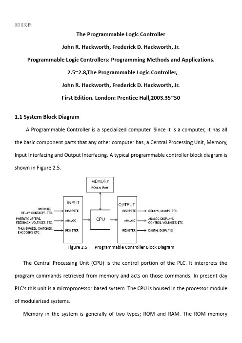
The Programmable Logic ControllerJohn R. Hackworth, Frederick D. Hackworth, Jr.Programmable Logic Controllers: Programming Methods and Applications.2.5~2.8,The Programmable Logic Controller,John R. Hackworth, Frederick D. Hackworth, Jr.First Edition. London: Prentice Hall,2003.35~501.1 System Block DiagramA Programmable Controller is a specialized computer. Since it is a computer, it has all the basic component parts that any other computer has; a Central Processing Unit, Memory, Input Interfacing and Output Interfacing. A typical programmable controller block diagram is shown in Figure 2.5.Figure 2.5 Programmable Controller Block DiagramThe Central Processing Unit (CPU) is the control portion of the PLC. It interprets the program commands retrieved from memory and acts on those commands. In present day PLC's this unit is a microprocessor based system. The CPU is housed in the processor module of modularized systems.Memory in the system is generally of two types; ROM and RAM. The ROM memorycontains the program information that allows the CPU to interpret and act on the Ladder Logic program stored in the RAM memory. RAM memory is generally kept alive with an on-board battery so that ladder programming is not lost when the system power is removed.This battery can be a standard dry cell or rechargeable nickel-cadmium type. Newer PLC units are now available with Electrically Erasable Programmable Read Only Memory (EEPROM) which does not require a battery. Memory is also housed in the processor module in modular systems.Input units can be any of several different types depending on input signals expected as described above. The input section can accept discrete or analog signals of various voltage and current levels. Present day controllers offer discrete signal inputs of both AC and DC voltages from TTL to 250 VDC and from 5 to 250 VAC. Analog input units can accept input levels such as ±10 VDC, ±5 VDC and 4-20 ma. current loop values. Discrete input units present each input to the CPU as a single 1 or 0 while analog input units contain analog to digital conversion circuitry and present the input voltage to the CPU as binary number normalized to the maximum count available from the unit. The number of bits representing the input voltage or current depends upon the resolution of the unit. This number generally contains a defined number of magnitude bits and a sign bit. Register input units present the word input to the CPU as it is received (Binaryor BCD).Output units operate much the same as the input units with the exception that the unit is either sinking (supplying a ground) or sourcing (providing a voltage) discrete voltages or sourcing analog voltage or current. These output signals are presented as directed by theCPU. The output circuit of discrete units can be transistors for TTL and higher DC voltage or Triacs for AC voltage outputs. For higher current applications and situations where a physical contact closure is required, mechanical relay contacts are available. These higher currents, however, are generally limited to about 2-3 amperes. The analog output units have internal circuitry which performs the digital to analog conversion and generates the variable voltage or current output.1.2 Update - Solve the Ladder - UpdateWhen power is applied to a programmable logic controller, the PLC’s operation consists of two steps: (1) update inputs and outputs and (2) solve the ladder. This may seem like a very simplistic approach to something that has to be more complicated but there truly are only these two steps.If these two steps are thoroughly understood, writing and modifying programs and getting the most from the device is much easier to accomplish. With this understanding, the things that can be undertaken are then up to the imagination of the programmer.You will notice that the “update - solve the ladder” sequence begins after startup. The actual startup sequence includes some operations transparent to the user or programmer that occur before actual PLC operation on the user program begins. During this startup there may be extensive diagnostic checks performed by the processor on things like memory, I/O devices, communication with other devices (if present) and program integrity. In sophisticated modular systems, the processor is able to identify the various module types, their location in the system and address. This type of system analysis and testing generally occurs during startup before actual program execution.1.3 UpdateThe first thing the PLC does when it begins to function is update I/O. This means that all discrete input states are recorded from the input unit and all discrete states to be output are transferred to the output unit. Register data generally has specific addresses associated with it for both input and output data referred to as input and output registers. These registers are available to the input and output modules requiring them and are updated with the discrete data. Since this is input/output updating, it is referred to as I/O Update. The updating of discrete input and output information is accomplished with the use of input and output image registers set aside in the PLC memory. Each discrete input point has associated with it one bit of an input image register. Likewise, each discrete output point has one bit of an output image register associated with it. When I/O updating occurs, each input point that is ON at that time will cause a 1 to be set at the bit address associated with that particular input. If the input is off, a 0 will be set into the bit address. Memory in today's PLC's is generally configured in 16 bit words. This means that one word of memory can store the states of 16 discrete input points.Therefore, there may be a number of words of memory set aside as the input and output image registers. At I/O update, the status of the input image register is set according to the state of all discrete inputs and the status of the output image register is transferred to the output unit.This transfer of information typically only occurs at I/O update. It may be forced to occur at other times in PLC's which have an Immediate I/O Update command. This command will force the PLC to update the I/O at other times although this would be a special case.One major item of concern about the first output update is the initial state of outputs.This is a concern because their may be outputs that if initially turned on could create a safety hazard, particularly in a system which is controlling heavy mechanical devices capable of causing bodily harm to operators. In some systems, all outputs may need to be initially set to their off state to insure the safety of the system. However, there may be systems that require outputs to initially be set up in a specific way, some on and some off. This could take the form of a predetermined setup or could be a requirement that the outputs remain in the state immediately before power-down. More recent systems have provisions for both setup options and even a combination of the two. This is a prime concern of the engineer and programmer and must be defined as the system is being developed to insure the safety of personnel that operate and maintain the equipment. Safety as related to system and program development will be discussed in a later chapter.1.4 Solve the LadderAfter the I/O update has been accomplished, the PLC begins executing the commands programmed into it. These commands are typically referred to as the ladder diagram. The ladder diagram is basically a representation of the program steps using relay contacts and coils. The ladder is drawn with contacts to the left side of the sheet and coils to the right.This is a holdover from the time when control systems were relay based.This type of diagram was used for the electrical schematic of those systems.A sample ladder diagram is shown in Figure 2-6.Figure 2-6 Sample Ladder DiagramThe symbols used in Figure 2.6 may be foreign at this point, so a short explana ---tion will be necessary. The symbols at the right of the ladder diagram labeled CR1, CR2, CR3 and CR4 and are circular in shape are the software coils of the relays. The symbols at the left which look like capacitors, some with diagonal lines through them , are the contacts associated with the coils. The symbols that look like capacitors with --out the diagonal lines through them are normally open contacts. These are analogous to a switch that is normally off. When the switch is turned on, the contact closes. The contact symbols at the left that look like capacitors with diagonal lines through them are normally closed contacts. A normally closed contact is equivalent to a switch that is normally turned on. It will turn off when the switch is actuated.As can be seen in Figure 2.6, contact and coil position is as described above. Also, one can see the reason for the term ladder diagram if the rungs of a stepladder are visualized. In fact, each complete line of the diagram is referred to as one rung of logic. The actual interpretation of the diagram will also be discussed later although some explanationis required here.The contact configuration on the left side of each rung can be visualized as switches and the coils on the right as lights.If the switches are turned on and off in the proper configuration, the light to the right will illuminate.The PLC executes this program from left to right and top to bottom, in that order.It first looks at the switch (contact) configuration to determine if current can be passed to the light (coil).The data for this decision comes from the output and input image registers.If current can be passed, the light (coil) will then be turned on.If not, the light (coil) will be turned off.This is recorded in the output image register Once the PLC has looked at the left side of therung it ignores the left side of the rung until the next time it solves that particular rung. Once the light (coil) has been either turned on or off it will remain in that state until the next time the PLC solves that particular rung.After solving a rung, the PLC moves on to solve the next rung in the same manner and so forth until the entire ladder has been executed and solved.One rule that is different from general electrical operation is the direction of current flow in the rung.In a ladder logic, rung current can only flow from left to right and up and down; never from right to left.As an example, in the ladder shown in Figure 2.7, coil CR1 will energize if any of thefollowing conditions exist:Figure 2.7 Illustration of allowed current flow in ladder rung1. CR7 is off, CR6 is on.2. CR7 is off, CR2 is on, CR5 is on.3. CR7 is off, CR2 is on, CR3 is on.4. CR1 is on, CR4 is on, CR3 is on.5. CR1 is on, CR4 is on, CR5 is on.You will notice that the current flow in the circuit in each of the cases listed above is from left to right and up and down. CR1 will not energize in the case listed below: CR1 is on, CR4 is on, CR2 is on, CR6 is on, CR5 is off, CR3 is off, CR7 is on.This is because current would have to flow from right to left through the CR2 contact. This is not allowed in ladder logic even though current could flow in this direction if we were to build it with real relays.Remember, we are working in the software world not the hardware world.To review, after the I/O update, the PLC moves to the first rung of ladder logic.It solves the contact configuration to determine if the coil is to be energized or de-energized.It then energizes or de-energizes the coil.After this is accomplished, it moves to the left side of the next rung and repeats the procedure.This continues until all rungs have been solved. When this procedure is complete with all rungs solved and all coils in the ladder set up according to the solution of each rung, the PLC proceeds to the next step of it's sequence, the I/O update.At I/O update, the states of all coils which are designated as outputs are transferred from the output image register to the output unit and the states of all inputs are transferred to the input image register.Note that any input changes that occur during the solution of the ladder are ignored because they are only recorded at I/O update time.The state of each coil is recorded to the output image register as each rung is solved. However, these states are not transferred to the output unit until I/O update time.Figure2.8 Scan CycleThis procedure of I/O update and solving the ladder diagram and I/O update is referred to as scanning and is represented in Figure 2.8. The period between one I/O update and the next is referred to as one Scan.The amount of time it takes the PLC to get from one I/O update to the next is referred to as Scan Time.Scan time is typically measured in milliseconds and is related to the speed of the CPU and the length of the ladder diagram that has to be solved .The slower the processor or the longer the ladder diagram, the longer the scan time of the system.The speed at which a PLC scans memory is referred to as Scan Rate.Scan rate units are usually listed in msec/K of memory being utilized for the program.As an example, if a particular PLC has a rated scan rate of 8 msec/K and the program occupies 6K of memory, it will take the PLC 48 msec to complete one scan of the program.1.5.MotivationProgrammable Logic Controllers (PLC), a computing device invented by Richard E. Morley in 1968, have been widely used in industry including manufacturing systems, transportation systems, chemical process facilities, and many others. At that time, the PLC replaced thehardwired logic with soft-wired logic or so-called relay ladder logic (RLL), aprogramming language visually resembling the hardwired logic, and reduced thereby the configuration time from 6 months down to 6 days [Moody and Morley, 1999 Although PC based control has started to come into place, PLC based control will remain the technique to which the majority of industrial applications will adhere due to its higher perfor- mance, lower price, and superior reliability in harsh environments. Moreover, according to a study on the PLC market of Frost and Sullivan [1995], an increase of the annual sales volume to 15 million PLCs per year with the hardware value of more than 8 billion US dollars has been predicted, though the prices of computing hardware is steadily dropping. The inventor of thePLC, Richard E Morley, fairly considers the PLC market as a5-billion industry at the present time.Though PLCs are widely used in industrial practice, the programming of PLC based control systems is still very much relying on trial-and-error. Alike software engineering, PLC software design is facing the software dilemma or crisis in a similar way. Morley himself emphasized this aspect most forcefully by indicating [Moody and Morley, 1999, p. 110“If houses were built like soft ware projects, a single woodpecker could destroy civilization.”Particularly, practical problems in PLC programming are to eliminate software bugs and to reduce the maintenance costs of old ladder logic programs. Though the hardware costs of PLCs are dropping continuously, reducing the scan time of the ladder logic is still an issue in industry so that low-cost PLCs can be used.In general, the productivity in generating PLC is far behind compared to other domains, for instance, VLSI design, where efficient computer aided design tools are in practice. Existent software engineering methodologies are not necessarily applicable to the PLC based software design because PLC-programming requires a simultaneous consideration ofhardware and software. The software design becomes, thereby, more and more the major cost driver. In many industrial design projects, more than SO0/a of the manpower allocated for the control system design and installation is scheduled for testing and debugging PLC programs [Rockwell, 1999].In addition, current PLC based control systems are not properly designed to support the growing demand for flexibility and reconfigurability of manufacturing systems. A further problem, impelling the need for a systematic design methodology, is the increasing software complexity in large-scale projects1.6.Objective and Significance of the ThesisThe objective of this thesis is to develop a systematic software design methodology for PLC operated automation systems. The design methodology involves high-level description based on state transition models that treat automation control systems as discrete event systems, a stepwise design process, and set of design rules providing guidance and measurements to achieve a successful design. The tangible outcome of this research is to find a way to reduce the uncertainty in managing the control software development process, hat is, reducing programming and debugging time and their variation, increasing flexibility of the automation systems, and enabling software reusability through modularity. The goal is to overcome shortcomings of current programming strategies that are based on the experience of the individual software developerDesign Theory DevelopmentToday, the primary focus of most design research is based on mechanical or electrical products. One of the by-products of this proposed research is to enhance our fundamental understanding of design theory and methodology by extending it to the field of engineeringsystems design. A system design theory for large-scale and complex system is not yet fully developed. Particularly, the question of how to simplify a complicated or complex design task has not been tackled in a scientific way. Furthermore, building a bridge between design theory and the latest epistemological outcomes of formal representations in computer sciences and operations research, such as discrete event system modeling, can advance future development in engineering designApplication in Logical Hardware DesignFrom a logical perspective, PLC software design is similar to the hardware design of integrated circuits. Modern VLSI designs are extremely complex with several million parts and a product development time of 3 years [Whitney, 1996]. The design process is normally separated into a component design and a system design stage. At component design stage, single functions are designed and verified. At system design stage, components are aggregated and the whole system behavior and functionality is tested through simulation. In general, a complete verification is impossible. Hence, a systematic approach as exemplified for the PLC program design may impact the logical hardware designPLCPLC (programmable logical controller )face ever more complex challenge these days. Where once they quietly relays and gave an occasional report to a corporate mainframe, they are now grounded into cells, give new jobs and new languages, and are forced to compete against a growing array of control products. For this year ’s annual PLC technology update, we queried PLC makers on these topics and moreProgramming languagesHigher level PLC programming languages have been around for some time, but latelytheir popularity has been mushrooming. As Raymond Lavelle, vice president and general manager, Siemens Energy and Automation. Inc, Programmable Controls Division, points out : ” As programmable controls are being used for more and more sophisticated operations, languages other than ladder logic become more practical, efficient, and powerful. For example, it's very difficult to write a trigonometric function using ladder logic. ” Languages gaining acceptance include Boolean, control system flowcharting, and such function chart languages as Graphtec and its variations. And these’s increasing interest in languages like C and BASIC.PLCs in process control Thus far, PLCs have not been used extensively for continuous process control. Will this continue? ”The feeling that I ’ve gotten, ” says Ken Jeannette, manager, product planning, Series One and Series Six products, at GE Frame North America, "is that PLCs will be used in the process industry but not necessarily for process control.”Several vendors-obviously betting that the opposite will happen-have introduced PLCs optimized for process applications. Rich Ryan ,manager, commercial marketing, Allen-Bradley Programmable Controls Div, cites PLCs ’ increasing use in such industries as food, chemicals,and petroleum. Ryan feel there are two types of applications in which they’re appropriate.”One,"he says, "is where the size of the process control system that's being automated doesn’t justify DCS[distributed control systems].With the starting price tags of those products being relatively high, a programmable controller makes sense for small, low loop count applications. The seconds where you have to integrate the loop closely with the sequential logic. Batch controller sere prime examples, where the sequence and maintaining the process variable are intertwined so closely that the benefits of having a programmable controller to do the sequential logic outweighs someof the disadvantages of not having a distributed control system.”Bill Barkovtz, president of Triconex, predicts that "all future controllers that come out in the process control system business will embrace a lot more PLC technology and a lot more PLC functionality than they ever did before.”中文翻译可编程逻辑控制器约翰R Hackworth,弗雷德里克 D Hackworth.可编程逻辑控制器:编程方法及应用.2.5~2.8,可编程逻辑控制器,约翰R Hackworth,弗雷德里克 D Hackworth第一版. 伦敦:普伦蒂斯霍尔出版社,2003,35~50一系统框图可编程控制器是一种专用的计算机。
基于PLC的电梯控制系统设计毕业设计(论文)

基于PLC的电梯控制系统设计毕业设计(论文)原创性声明和使用授权说明原创性声明本人郑重承诺:所呈交的毕业设计(论文),是我个人在指导教师的指导下进行的研究工作及取得的成果。
尽我所知,除文中特别加以标注和致谢的地方外,不包含其他人或组织已经发表或公布过的研究成果,也不包含我为获得及其它教育机构的学位或学历而使用过的材料。
对本研究提供过帮助和做出过贡献的个人或集体,均已在文中作了明确的说明并表示了谢意。
作者签名:日期:指导教师签名:日期:使用授权说明本人完全了解大学关于收集、保存、使用毕业设计(论文)的规定,即:按照学校要求提交毕业设计(论文)的印刷本和电子版本;学校有权保存毕业设计(论文)的印刷本和电子版,并提供目录检索与阅览服务;学校可以采用影印、缩印、数字化或其它复制手段保存论文;在不以赢利为目的前提下,学校可以公布论文的部分或全部内容。
作者签名:日期:学位论文原创性声明本人郑重声明:所呈交的论文是本人在导师的指导下独立进行研究所取得的研究成果。
除了文中特别加以标注引用的内容外,本论文不包含任何其他个人或集体已经发表或撰写的成果作品。
对本文的研究做出重要贡献的个人和集体,均已在文中以明确方式标明。
本人完全意识到本声明的法律后果由本人承担。
作者签名:日期:年月日学位论文版权使用授权书本学位论文作者完全了解学校有关保留、使用学位论文的规定,同意学校保留并向国家有关部门或机构送交论文的复印件和电子版,允许论文被查阅和借阅。
本人授权大学可以将本学位论文的全部或部分内容编入有关数据库进行检索,可以采用影印、缩印或扫描等复制手段保存和汇编本学位论文。
涉密论文按学校规定处理。
作者签名:日期:年月日导师签名:日期:年月日注意事项1.设计(论文)的内容包括:1)封面(按教务处制定的标准封面格式制作)2)原创性声明3)中文摘要(300字左右)、关键词4)外文摘要、关键词5)目次页(附件不统一编入)6)论文主体部分:引言(或绪论)、正文、结论7)参考文献8)致谢9)附录(对论文支持必要时)2.论文字数要求:理工类设计(论文)正文字数不少于1万字(不包括图纸、程序清单等),文科类论文正文字数不少于1.2万字。
基于plc电梯控制外文文献翻译、中英文翻译、外文翻译
In the article has analyzed the elevator loadcharacteristics, elaborated uses the trapezoid acceleration curve theelevator ideal velocity curve, unifies the frequency changer and thePLC performance, elaborated the elevator control system constitutionand the operational factor. Elaborated the elevator speed curveproduces the method, has induced the characteristic which designs byPLC constitution control system software.Key word: Load characteristics ideal velocity curve control systemsoftware design1. OutlineAlong with the urban construction unceasing development, thehigh-rise construction unceasingly increases, the elevator has thewidespread application in the national economy and the life. Theelevator took in the high-rise construction the vertical movementtransportation vehicle already and people's daily life is inseparable.In fact the elevator is according to exterior movement and so oncalling signal as well as own control rule, but calls is stochastic,the elevator is a person machine interactive control system in fact,purely is cannot satisfy the control request with the sequentialcontrol or the logical control, Therefore, the elevator control system uses the stochastic logical waycontrol. At present the elevator control generally has selected twomethods, one is uses the microcomputer to take the signal controlunit, completes the elevator signal gathering, the running status andthe function hypothesis, realizes the elevator automatic dispatch andthe collection chooses the movement function, drives the control tocomplete by the frequency changer; The second control mode (PLC)substitutes for the microcomputer realization signal collection withthe programmable controller to choose the control. Said from the control mode and the performance, these two methodscertainly not too big difference. The domestic factory mostly choosesthe second way, its reason lies in the production scale slightly, owndesign and the manufacture microcomputer control device cost ishigher; But PLC reliability high, programming convenience nimble, theantijamming ability strong, the movement stable is reliable and so onthe characteristic, therefore the present elevator control systemwidely uses the programmable controller to realize.2. Elevator ideal performance diagramIndicated according to the massive research and the experiment, theperson may accept the maximum acceleration is am <= 1.5m/s2,acceleration rate of change rho m <= the 3m/s3, elevator idealperformance diagram may divide according to the acceleration is thetriangle, the trapezoid and the sine profile, As a result of sine profile acceleration curve realization moredifficult, but the triangle curve maximum acceleration and is startingand applies the brake the section turning point acceleration rate ofchange to be bigger than the trapezoidal curve, namely + rho m jumpsto - rho m or jumps from - rho m to + rho the m acceleration rate ofchange, therefore very little uses, because the trapezoidal curve iseasy to realize and has the good acceleration rate of change frequenttarget, therefore is widely used, uses the trapezoidal accelerationcurve elevator ideal performance diagram like chart 1 to show: The intelligent frequency changer is for the elevator special-purposefrequency changer request and so on elevator nimble velocitymodulation, control and high accuracy even level which but speciallydesigns, may use for parts the general three-phase asynchronous motor,and has function and so on intellectualized software, standardconnection, menu prompt, input elevator curve and other essentialparameter. It has the debugging convenience quickly, moreover can automaticallyrealize the single multilayered function, and has the automaticoptimization deceleration curve the function, is composed the velocitymodulation system crawling time by it few, the even level distance isshort, no matter is the double winding electric motor, or electric motor suitable, its highest design speed may reach 4m/s, itsunique computer monitoring software, may choose the serial interfacerealization input/output signal the non- electronic contact control. The frequency changer constitutes elevator system, when the frequencychanger receives the controller to send out shouts the ladderdirection signal, the frequency changer basis hypothesis speed and theacceleration value, the starting motor, after achieved the maximumspeed, the uniform speed moves, when arrives the goal leveldecelerates, the controller sends out shuts off the high velocitysignal, reduces the speed which the frequency changer establishes themaximum speed to reduce to the crawling speed, In decelerates in the movement process, the frequency changer can theautomatic computation decelerate to the even level spot betweendistance, and calculates the optimized curve, thus canaccording tothe optimized curve movement, cause the low speed crawling time toreduce to 0.3s, the frequency changer through adjusts leveling thespeed in the elevator even level process or applies the brake thepitch to adjust leveling the precision. Namely when the elevator stops too early, the frequency changerincreases the low speed value or the reduction applies the brake thepitch value, otherwise reduces the low speed value or increasesapplies the brake the pitch value, when the elevator to leaves evenlevel position 4 - 10cm, has the even level switch automaticseparation low speed signal, the system according to the optimizedcurve realization high accuracy even level, thus achieved the evenlevel accurate is reliable.3. Elevator speed curveElevator movement comfortableness is decided in its movementprocess acceleration a and the acceleration rate of change p size, theoversized acceleration or the acceleration rate of change can createpassenger's ill feeling. At the same time, for guaranteed the elevatorthe operating efficiency, a, the p value not suitable excessively issmall. Can guarantee a, the p best value elevator performance diagramis called the elevator the ideal performance diagram. The elevatormovement ideal curve should be the parabola - straight linecomprehensive velocity curve, namely elevator Canada, reduces theprocess constitutes by the parabola and the straight line. Theelevator assigns the curve is whether ideal, direct influence actualperformance diagram.3.1 velocity curves have the methodUses FX2-64MR PLC, and a consideration input output requestincreased FX-8EYT, FX-16EYR, the FX-8EYR three expansions modules andthe FX2-40AW twisted pair line correspondence adapter, FX2-40AW usesin the system serial communication. Using PLC the expansion functionmodule D/A module realization speed ideal curve output, whenbeforehand the digitized ideal velocity curve stores the PLC register,the procedure movement, through looks up the table way to read in D/A,transforms the simulation quantity after D/A the speed ideal curveoutput.3.2 Acceleration assign the curve the production8 D/A outputs 0 ~ 5V/0 ~ 10V, the corresponding numerical valueis 16 enters system several 00 ~ FF, altogether 255 levels. Ifelevator rise time between 2.5 ~ 3seconds. According to theconservative value computation, in the elevator acceleration processeach time Zha Biao time-gap not suitably surpasses 10ms.As a result of elevator logic control section procedure biggest, butthe PLC movement uses the cyclical scanning mechanism, thus usuallyuses looks up the table method, Zha Biao instruction time-gapexcessively is each time long, cannot satisfiedly assign the curve theprecision request. In the PLC movement process, its CPU with variousequipment between exchange of information, user program execution,signal gathering, control quantity operation and so on output all isdefers to the fixed order to circulate the scanning way to carry on,each circulation all must carry on the inquiry, the judgement and theoperation to all functions. This kind of order and the form capableperson are not the change. The usual scanning cycle, is basic mustcomplete six steps the work, including movement surveillance, andprogramming exchange information, and digital processor exchangeinformation, and communication processor exchange information,execution user program and input output connection service and so on.In a cycle, CPU only carries out to the entire user program. This kindof mechanism has its convenient one side, but timeliness is bad. Theexcessively long scanning time, directly affects the system to thesignal response effect, in under the guarantee control functionpremise, maximum limit reduces CPU the cyclical scanning time is avery complex question. Generally only can short adopt the method fromthe user program execution time. The elevator logic control sectionprocedure scanning time has surpassed 10ms, although has adopted somereduced procedure scanning time means, but still will be unable toscan the time to fall to 10ms below. At the same time, applies thebrake the section curve to use according to is away from theprinciple, each section of distances arrive the response time notsuitably surpasses 10ms. In order to satisfy the system the timelyrequest, in the velocity curve production way, uses the severancemethod, thus effectively has overcome the PLC scanning mechanismlimit.The starting acceleration movement by decides the cycle interruptservice isr to complete. This kind of severance cannot carry on theswitch by the procedure, once establishes, continuously presses thehypothesis time-gap circulation severance,therefore, the startingmovement condition must put in the interrupt service isr, when doesnot satisfy the movement condition, the severance namely returns.3.2 Decelerates applies the brake the curve productionIn order to guarantee applies the brake process completing,must carry on in the master routine applies the brake the condition tojudge and to decelerate a determination. In decelerates before adetermination, the elevator continuously is in the acceleration or thesteady fast movement process. The acceleration process completes bythe fixed cyclical severance, accelerates after the correspondingpattern maximum value, the acceleration procedure movement conditionno longer satisfies, after each time severs, no longer carries out theacceleration procedure, directly returns from the severance. Theelevator corresponds the pattern the maximum value movement,decelerates in this pattern to after, has the high-speed countingseverance, the execution decelerates the service routine. Revises thecounter in this interrupt service isr to suppose the definite valuethe condition, guaranteed the next time will sever the execution. In the PLC internal register, deceleration curve table value from big to small , each time severs all carries out time "theindicator needle to add 1" the operation, then the next severance willlook up the table number is smaller than this severance to look up the table numbers. Thegate area peaceful level area judgement produces by exterior signal,guarantees the moderating process the reliability.4. Elevator control system4.1 Elevators control system characteristicIs relates the elevator movement comfortable feeling target in theelevator performance diagram start section the key link, but thecomfortable feeling with the acceleration direct correlation,according to controls the theory, must cause some quantity accordingto prearrange the rule change to have to carry on the positivegoverning to it, said regarding the elevator control system, mustcause the acceleration to have to use the acceleration feedbackaccording to the ideal curve change, according to electric motormoment of force equation: M - MZ= Delta M=J (dn/dt), obviously theacceleration rate of change had reflected the system dynamic extensionis apart from the change, the control acceleration is apart from DeltaM=M - MZ on the control system dynamic extension. Therefore uses theacceleration in thissection the timing control principle, when thestart ascent portion speed achieved when stable state value 90%,systematically will cut the speed control from the accelerationcontrol, because in the steady fast section, the speed will besmaller for the permanent value control undulation, the accelerationchange will not be big, also will use the speed closed-loop controlto be allowed to cause the stable state speed hold certain precision,will be applies the brake the section precise even level to create thecondition. Uses the PI regulator control in the system speed ascentportion and steady fast Duan Suidu, but two section of PI parameter isdifferent, enhances the system the dynamic response target.Applies the brake the section in the system, namely must to reduce thespeed to carry on the essential control, guarantees the comfortablefeeling, also must strictly controls according to the elevatormovement speed and the distance relations, guarantees the even levelthe precision. In system’s rotational speed reduces to 120r/min in front of, in orderto enable two to obtain the proper attention to both, adopts by theacceleration to the timing control primarily, simultaneously actsaccording to on each as soon as the stopping distance the actualrotational speed and the theory rotational speed deviation revises theacceleration to assign the curve the method. For example in is awayfrom the even level spot some as soon as to be away from L place, thespeed should reduce to Vm/s, but the actual rotational speed is highis V ' m/s, then explained adds the system turns is apart frominsufficiently, after therefore calculates the here to assign reducesspeed value -ag, causes it to add on a negative deviation againepsilon, even if the here reduces the speed given value to revise for- (ag+ epsilon) causes to assign reduces the speed and the true speednegative deviation enlarges, thus enlarged the system to turn thedistance, caused the speed very quickly to fall to the standard value,when electric motor’s rotational speed reduces to 120r/min after, this time thetheater box above the level only had several centimeters, The elevatorrunning rate is very low, for did not prevent phenomenon appearancewhich stops to the even level area, enables the elevator comparativelyquickly to enter the even level area, uses the proportional control inthis section, and uses the time optimization control, guaranteed theelevator accurately promptly enters the even level area, achieves theaccurate reliable even level.4.2 elevators controls constitutionBecause the elevator movement is according to the floor and the theater box calling signal, the travelling schedule signalcarries on the control, but the floor and the theater box call isstochastic, therefore, the systems control uses the stochastic logicalcontrol. Namely in realizes in the elevator basic control requestfoundation by the smooth logic control, according to stochastic inputsignal, as well as elevator corresponding condition at the rightmoment control elevator movement. Moreover, the theater boxposition is determined by the pulse encoder pulse number that, anddelivers PLC the counter to carry on the control. At the same time,each building establishes to approach the switch to use in to examinethe system the floor signal. In order to be advantageous for the observation, is at the floor tothe elevator movement direction as well as the elevator to carry onthe demonstration, uses LED and the photo tube demonstrated, but tothe floor and the theater box calling signal to the indicating lampdemonstrated (on switch has indicating lamp).In order to enhance the elevator the operating efficiency peacefullevel precision, the system requests PLC to be able to theater boxCanada, to decelerate as well as to apply the brake to carry on theeffective control. Realizes according to the theater box physicallocation as well as the exchange velocity modulation system controlalgorithm. For the elevator movement security, the system shouldestablish the reliable fail safe and the corresponding es the PLC realization the elevator control system to constitute byfollowing several main parts.4.2.1 PLC control circuit; PLC receives shouts the ladder from thepanel board and each level to summon the signal, the theater boxand the gate system function signal as well as the well and thefrequency changer condition signal, realizes the elevator collectionafter the procedure judgement and the operation to choose the control.PLC during the output demonstration and supervisory signal, sends outthe movement direction, the start, Canada to the frequencychanger/decelerates moves and applies the brake to stop the ladderequisignal.4.2.2 electric currents, speed double closed loops electric circuit;Frequency changer itself is equipped with the electric currentdetector set, from this constitution electric current closed loop;Through revolves the encoder with the electricalmachinery coaxialjoint, produces a, the b two pulses enters the frequency changer,during confirmation direction, counts the constitution speed closedloop using the pulse.4.2.3 displacements control circuit; The elevator took one kindcarries the person tool, reigns under the potential state of loading,besides request safe reliable, but also requests the movement to besteady, rides comfortably, anchors accurately. Uses the frequencyconversion to modulate velocity Shuanghuan to control may basicallyanswer the purpose, the use existing revolves the encoder toconstitute the speed ring at the same time, moves the proportionthrough the frequency changer PG card output and the electricalmachinery speed and the elevator the pulse number, introduces it PLChigh-speed counting to input the port, through the accumulation pulsenumber, (1) calculates the pulse equivalent after the type, from thisdefinite elevator position. Elevator displacement H=SI In the formula I - accumulation pulse number; S - pulse equivalent; S = plD/(pr) (1) L – Proportion of decelerates ; D - tows the wheel diameter; P - revolves the encoder every time to transfer corresponding thepulse number; R - PG card frequency division ratio.4.2.4 ends stations protection; When in elevator direction detectionline, on the good directional relay, the express train assistancecontact device, the express train movement contact device, the doorlock relay, on the good contact device electricity attracts gathers, mechanical floodgate opens, on elevator line. When the theater box bumps intoforces speed changeing the switch, the PLC internal lock saves the relay toresult in the electricity to attract gathers, timer Tim10, Tim11 startfixed time, it fixed time time length visible end station leveldistance with ladder fast hypothesis. After on forces speed changing theswitch movement, the elevator transfers the slow train movement by theexpress train movement, in the normal condition, the previous line ofeven strata time elevator should stop. If the theater box has notstopped continues the line, when Tim10 supposes the definite value toreduce the zero hour, it the separation, the slow traincontact device and on the good contact device loses the electricity,the elevator stops moving. Bumps into after the arrogant theater boxon forces speed changing the switch, because certain reason elevators have notbeen able to transfer the slow train movement, and the express trainmovement contactdevice has not been able to release, when Tim11supposes the definite value to reduce the zero hour, it N.C. contactthe separation, the express train movement contact device and on thegood contact device loses the electricity, the elevator stops moving.Therefore, no matter is the slow train movement or the express trainmovement, so long as on forces speed changing the switch to send out thesignal, no matter the end stands other protection switches whetheract, can cause the elevator with the aid of Tim10 and Tim11 to stopmoving, thus causes the elevator end station protection to be morereliable.Under when the elevator needs the line, so long as had has chosen theladder instruction, got down the good directional relay to result inelectricity its Chang Kaidian closed, the lock saved the relay toreposition, Tim10 and Tim11 lost the electricity, it N.C. contactclosed for the elevator normal under line has prepared for. The lowerextremity stands the protection principle and the upper extremestation protection similar no longer duplicates.4.2.5 floors count; The floor counts uses relatively counts the way.Before the movement through from the study way, determines thecorresponding floor highly pulse number, corresponds 17 elevatorsseparately to store 16 memories units DM06 ~ DM21. The floor counter(CNT46) is a bidirectional counter, when arrives each level the floorcounts, according to moves the direction to carry on adds 1 or reduces1 to count. In the movement, the high speed counter tiredly estimates the valuereal-time counts the point correspondence pulse number with the floorto carry on the comparison, is equal when sends out the floor to countthe signal, the previous line of Canada 1, the next line reduces 1. Inorder to prevent the counter in counts the pulse high level periodrepetition to count, uses the floor to count on the signal along totrigger the floor counter.4.2.6 is fast speed changing; When the high speed counter value and the fastspeed changing point correspondence pulse number is equal, if the elevator isin the quick operating also this level has chooses the level signal,sends the fast speed changing signal. If the elevator medium speed movement oralthough the quick operating but this not chooses the level signal,then does not send speed changing the signal.4.2.7 areas signals; When high speed counter CNT47 value correspondsin the pulse number scope when the gate area, sends the gate areasignal.4.2.8 pulses signals failure detection; Pulse signal accurategathering and the transmission appears in the system especiallyimportantly, revolves the encoder for the examination and the pulsetransmission circuit breakdown, whether there is has designed thepulse signal and the errors and omissions pulse examination electriccircuit, guarantees the system normal operation through the real-timeexamination. In order to eliminate the pulse to count the accumulativeerror, in base station the establishment reset switch, turns on PLC highspeed counter CNT47 the replacement end.5. Software design characteristic5.1 uses the priority formationPosition and movement direction locates which according to theelevator, in the programming, has used four priorities formations,namely on good priority formation, on line of inferior priorityformation, under good priority formation, next line of inferiorpriority formation. When among them, on good priority formation forelevator upward movement, locates the upward movement calling signalin the elevator which above the position the floor sends out, thearray which should call which the signal cabin correspondence thefloor to have the pulse number depositing register constitutes. Whenprevious line of inferior priority formation for elevator upwardmovement, locates the upward movement calling signal in the elevatorwhich below the position the floor sends out, the formation whichshould call which the signal cabin correspondence the floor to havethe pulse number depositing register constitutes. Control system inelevator movement real-time arrangement four priorities exhibition,has provided the foundation for the realization stochastic logiccontrol.5.2 uses advanced first leaves the formationAccording to elevator movement direction, with to the priorityformation's in non-vanishing unit (has when call this unit is 70units, does not have when call then this unit for zero) (advancedsends in the register formation first to leave formation FIFO), theuse advanced first leaves the read-out instruction SFRDP instruction,sends in the FIFO first unit in data compares the register.5.3 uses the stochastic logical controlWhen the elevator approaches by some movement direction somefloor decelerates the position, distinguished whether this floor doeshave with to the calling signal (on a line of call symbolizedregister, next line of call symbolized when register, has callrequest, corresponding register is l, otherwise is 0), if has, thecorresponding register pulse number and the comparison register willcarry on the comparison, if will be same, then will decelerate in thisfloor stops: If is not same, then sends in this register data comparesthe register, and the original comparison register data preservation,carries out this floor to decelerate stops. After this movementfinished, the data which will preserve reis sent in compares theregister, will realize the stochastic logical control.5.4 uses the software demonstration The system use travelling schedule judgement floor, andtransforms the BCD code output, through hardware connection electriccircuit by LED demonstration.5.5 pair of frequency changers control PLC acts according to the stochastic logical control therequest, may send out to the frequency changer to the movement, thereverse movement, is decelerating as well as applies the brake thesignal, again controls the electrical machinery by the frequencychanger basis certain control rule and the control algorithm. At thesame time, when the system appears the breakdown, PLC to the frequencychanger sends out the signal.6. Concluding remark Uses elevator control system which the MIC340 elevatorspecial-purpose frequency changer constitutes, may realize theintellectualization which the elevator controls, but because theperiod of five days ladder and the elevator in person arrives eachlevel the population is the intelligent elevator is unable todetermine, even if uses the AITP artificial intelligence system, thetransmission transportation passenger flow information also is fuzzy,for solves the elevator this vertical transportation control systemtwo to be big cannot know the factor, will need us to go to theunceasing research and the exploration in the next work.译文:文中分析了电梯的负载特性,阐述了采用梯形加速曲线的电梯理想速度曲线,结合变频器和PLC的性能,论述了电梯控制系统的构成和工作特性。
基于PLC的电梯控制系统文献

Intelligence BuildingIn 1980s the first intelligence mansion had been completed in America, then intelligence building has been a broadly taken attentions by the whole world. The concept of intelligence building has been put different meanings along with the development of society. The early stage intelligence building had been thought that it is equal to the intelligence mansion, but now the intelligence building not only includes the intelligence mansions but also involves intelligence residential districts. This paper mainly discusses one subsystem of intelligence building system: the elevator control system.In intelligence residential districts the enterprise’s information managing system mainly takes charge of the things which related to the daily life, for example supervising the district equipments, managing vehicles, disposing critical situations and so on.The elevator supervising and control system is also necessary to the intelligence residential districts. How to make people feel safe, stable and comfortable and how to save energy resources and protect environments and so on are the basic requirements to the elevator control system.PLC is a common industry control device. It is a special industry control computer which has the perfect function and simple frame. The PLC strong ability in interference and so on makes the elevator industry one after another to apply the PLC to the elevator control system, in order to replace the relay being used in traditional elevator control system. The Application of PLC in the elevator control system reduces the breakdown rate and efficiently improves the operating reliability of the elevator with safety. This paper mainly discusses the elevator control system’s working principles, the system’s software and hardware realization methods and so on.The Working Principles of Elevator Control System are stated as follows: The spot control information is send into the PLC from the customer input devices firstly, then the PLC control cabinet is required to send out the control signal to drive the equipments according to the system demands. The elevator can then perform the homologous action according to the control request. There are velocity feedback devices in system, which adopt measure velocity generators to provide the elevator velocities and generally are installed in the tail of tow motors. So this is a feedback control system, which can improve the system’s control precision.It is not necessary to do interface circuit in the elevator’s PLC control system. What we should do is to send the signals to PLC digital input terminals. The signals include inside and outside calling signals, floor location inspecting signals, limiting location signals, opening and shutdown the elevator door signals etc. The DC power which is provided to PLC can be used as indicator light power. The PLC output points can be directly used to control transducers for the purpose of electrical motor’s positive turn and reverse, stop and control each segment velocity and so on.Moreover, input and output devices are needed in elevator control system, besides the PLC, system’s major control device.The control cabinet is the control center, from which we can send out various control commands. The control cabinet often was installed in the elevator room. The electric devices and signal systems, for example the contactors, relays, capacitances, resistors, rectifiers and transformers etc, are centralized in the control cabinet. The Power of the control cabinet wasderived from control cabinet was delivered to tow electric motors. Others control lines and signal lines were separately sent to each floor junction.The design includes two parts: hardware and software. The hardware design is the base of software. Considering that the control demands are relatively complex, we design the programs separately according to the control function. Furthermore, we follow the principle as follows: When the elevator is ascending, the ascending demands are prior to other demands.When the elevator is descending, the descending demands are prior to other demands. The Sequential Function Chart(SFC) is adopted during the boxes to form elevator’s executive circuitry design. It is a method specially used in industrial sequential control. The SFC method can describe the system’s working procedure in great detail.When all SFC are drawn and I/O address lists are presented, we can convert the SFC to Ladder Diagram(LD). Considering the strict demands for time and for locked each other, we introduce working bits to remember working steps. We should write out the working bits control program, which can link together each step and make the pervious step as the next step restriction condition. Thus the actual outputs are the logic combination of these working steps.The system program has been debugged completely at present. Simulated experiment enunciates that the design method is viable. Application of PLC in the elevator control system is an effective method. It can make the personnel of the industry management center to long-distance monitor and control the elevator in control center, to connect the elevator system with intelligence building industry management system by Ethernet or special-purpose network such as Lon Works. The elevator, but also can lower the elevator maintenance costs etc. It is one of the developing direction of intelligence building elevator control system.Lift control systemLift control system is used to manipulate each control process by managing such commands as running direction, car call, landing call, load signal, landing indication, safety protection.Lifts in different applications have different load, speed and drive / control modes. Lifts in same application may also have different control mode. Whatever control mode is adopted, the objective is the same, to be specific, according to car call and landing call, lift control system will execute automatic logic judgment to determine which lift will receive signal, which direction lift will run towards and complete programmed control objective through electrical automatic system based on command.Types of lift control systemControl system development chronicle indicates that there has appeared many control modes, such as such as relay control, PLC, single computer control, multiple-computer control. Prevailing in different era, these control modes are still employed in lifts now due to massive integrated circuit and computer technology development.PLC control systemAs abbreviation of programmable logic controller, PLC is an electronic system featuring digital computation. It adopts programmable EPROM to execute logic computation, order control, timing, number counting, arithmetic computation, besides, it can input and output through digital or analogy modes.while output of PLC includes contactor, relay, indicators of car / landings and communication unit.ay, indicators inside car and switch, position signal, are input to PC, while other executing comProgramming principle is determined by lift control mode. Programming can either be made according to relay logic control circuit or individually in different phases according to lift control functions after completely separating from relay control circuit. Based on the ready made control circuit, the former is simple and easy to master, while the latter involves less programs by integrating programs of small function.Used in lift control system, PLC has such advantages, as high reliability, stability, easy programming, user-friendliness, convenient maintenance & inspection.Nowadays, there is a wide range and series of programmable logic controllers. Input / output points range from 30 to 8000 or above, so as to meet lift control requirements with different landing number.译文PLC在智能建筑电梯控制系统中的应用在20世纪80年代,第一座智能大厦在美国竣工,之后智能建筑引起了全世界的关注。
plc电梯控制系统毕业论文
plc电梯控制系统毕业论文PLC电梯控制系统毕业论文摘要本文介绍了一种基于PLC(可编程逻辑控制器)的电梯控制系统。
本文首先分析了电梯的基本结构和工作原理,然后介绍了PLC技术的基本概念和特点。
通过对电梯控制系统的需求分析,提出了一种基于PLC的电梯控制系统架构设计方案。
根据设计方案,编写了PLC程序,并按照实际情况进行了测试。
测试结果表明,本文设计的电梯控制系统能够实现电梯的基本功能,并能够有效避免电梯故障的发生。
关键词:PLC;电梯;控制系统;架构设计;程序编写AbstractThis paper introduces a PLC-based elevator control system. Firstly, the basic structure and working principle of elevator are analyzed, and then the basic concepts and characteristics of PLC technology are introduced. Based on the requirement analysis of elevator control system, a PLC-based elevator control system architecture design scheme is proposed. According to the design scheme, the PLC program is written and tested according to the actual situation. The test results show that the elevator control system designed in this paper can realize the basicfunctions of elevator and effectively avoid the occurrence of elevator failures.Keywords: PLC; elevator; control system; architecture design; program writing一、绪论1.1 研究背景电梯是一种用于垂直运输人员和物品的交通工具。
【机械类文献翻译】PLC控制下的电梯系统

机械专业中英文文献翻译Elevator System Based on PLCComposed by the order of relay control system is a realization of the first elevator control method. However, to enter the nineties, with the development of science and technology and the widespread application of computer technology, the safety of elevators, reliability of the increasingly high demand on the relay control weaknesses are becoming evident.Elevator control system relays the failure rate high, greatly reduces the reliability and safety of elevators, and escalators stopped often to take with the staff about the inconvenience and fear. And the event rather than taking the lift or squat at the end of the lift will not only cause damage to mechanical components, but also personal accident may occur.Programmable Logic Controller (PLC) is the first order logic control in accordance with the needs of developed specifically for industrial environment applications to operate the electronic digital computing device. Given its advantages, at present, the relay control the lift has been gradually replaced by PLC control. At the same time, AC variable frequency motor speed control technology, the way the lift drag speed has been a gradual transition from DC to AC frequency converter. Thus, PLC control technology increases VVVF Elevator modern technology has become a hot industry.1. PLC elevator control advantages(1) used in elevator control PLC, with software for automatic control of liftoperation, reliability greatly increased.(2) layer was removed and a majority of the relay, the control system structure issimple, to simplify the external circuit.(3) PLC can be a variety of complex control system, easy to add or changecontrol functions.(4) PLC can be automated fault detection and alarm display to improve theoperation of security and ease of maintenance.(5) for the group control the allocation and management, and improve theefficiency of elevator operation.(6) do not need to change the control scheme changes when the hardware connection.2. VVVF elevator control characteristicsWith the power electronics, microelectronics and computer technology to control the rapid development of technology, communication technology VVVF also a very rapid rate. AC variable frequency motor speed control technology is the power to improve the process in order to improve product quality and improving the environment and promoting technological progress as a primary means. Frequency of its excellent performance and the speed brake from a smooth performance, high efficiency, high power factor and power-saving effect of a broad scope of application and many other advantages of being at home and abroad recognized as the most promising approach speedExchange characteristics of VVVF Elevator(1)low energy consumption(2) low load circuit, the required emergency power supply device of smallIn the acceleration stage, the required start-up current of less than 2.5 times the rated current. Peak starting current and time is short. Since the starting current is drastically reduced, so power consumption and power supply cable diameter can be reduced a lot. Required for emergency power supply devices are also relatively small size.(3) high reliability and long service life.(4) good comfortElevator operation is best to follow the speed curve of a given operation. Their characteristics can be adapted to human feelings, and to ensure that noise operation, smooth brakePing layer and high precision(5) Stable noise-free(6) In the car, the engine room and adjacent areas to ensure that noise. Because their systems use a high clock frequency. Always produce a true sine wave power supply current yet. Motor torque ripple does not appear. Therefore, to eliminate vibration and noise.3. Elevator control technologyThe so-called elevator control technology refers to the elevator drive system and electrical control system of automatic control. 70 as the 20th century in China's elevator was marked by the exchange of two-speed elevator. Its speed is used to change the elevator traction motor of the very few, two or multi-level approach to the number of windings, very few of them as high-speed winding of the winding, a very few number of windings as the low-speed winding. Windings for high-speedelevator-speed start-up and running, low-speed windings for braking and the maintenance of elevators.The early 80s, VVVF inverter controlled variable lift system available. It uses AC motor drives, are able to reach the level of DC motor, control the speed of the current has reached 6 m / sec. Its small size, light weight, high efficiency, energy saving, including the past almost all the advantages of the lift. Is the latest elevator drive system.Operation in vertical lift, there is also the starting point of the terminus station. For more than three-story elevator buildings, the starting point of the terminal stations and stops between the had not, the starting point for these stations at the first floor of the terminal located at the highest floor. Starting point in the first floor of the station known as base stations, known as the starting point at both ends of the terminal stations and stations at both ends of intermediate stops between stations.Outside the station has a call box, box set are used by staff for elevator call button or touch the call button, the general ends of the lift stations in the call box on the Settings button or touch of a button. Middle layer of the station set up the call box button or touch button 2. No drivers for the control of elevators, at various stations are set up calls me on a button or touch button. Elevator car and the internal settings (except for debris elevator) to manipulate me. Control box switch on the handle or set up stations and the corresponding layer of buttons or touch-button control box on the touch-control button or command button or touch the city button. Outside the command button or touch-button issue as the signal outside the command signal, within the command button or touch-button issue within the signal as a command signal. 80 In the mid-20th century, the touch button has been replaced by micro-button.As the elevator call box outside the base station, in addition to set up a call button or touch button, but also set a key switch in order to work the elevator clearance. Drivers or management staff to open the elevator to the base station can wriggle through a dedicated key to the key switch. Close the elevator in place to automatically cut off the elevator control power supply or power supply.4. PLC Control Elevator DesignWith the continuous development of urban construction, the increasing high-rise buildings, elevators and life in the national economy has a broad application. Elevator high-rise buildings as a means of transport in the vertical run of daily life has beeninextricably linked with people. In fact the lift is based on external call control signals, as well as the laws of their own, such as running, and the call is random, the lift is actually a man-machine interactive control system, simple to use control or logic control order can not meet the control requirements, and therefore , elevator control system uses a random control logic. Elevator control is currently generally used in two ways, first, the use of computer as a signal control unit, the completion of the lift signal acquisition, operation and function of the set, to achieve the lift and set the automatic scheduling function to run the election, drag the control from inverter to complete; the second control mode with programmable logic controller (PLC) to replace the computer control signal sets the election. From the control and performance, these two types of methods and there is no significant difference. Most of the domestic manufacturers to choose the second approach, because the smaller scale of production, their design and manufacture of high cost of computer control devices; and PLC high reliability, convenient and flexible program design, anti-interference ability, stable and reliable operation of the characteristics of Therefore, the elevator control system is now widely used to realize programmable controller.5. Elevator control system characteristicsOperation of the lift curve is above the start to run comfort indicators lift the key features, and comfort are directly related with the acceleration, according to control theory, for a certain amount of change according to the law must be directly controlled, for elevator control system, according to the ideal acceleration curve acceleration feedback to be used, in accordance with the motor torque equation: M-MZ = ΔM = J (dn / dt), can be seen reflected in the rate of change of acceleration of the system of dynamic torque changes on the control system to control the acceleration of the dynamic torque ΔM = M-MZ. Therefore, during this time to control the use of the principle of acceleration, when the start rate of increase in steady-state value above 90%, the acceleration control system by the switch to speed control, as in paragraph steady speed, speed control for the constant fluctuations in the smaller, little change in acceleration, speed and the use of closed-loop control can maintain a steady-state speed accuracy and precision for the braking section to create the conditions ping layer. Is rising at a rate in the system, and although the above-speed PI regulator used to control, but two of the PI parameters are different in order to improve the system dynamic response indicators. The brake in the system,that is, to reduce the speed of control necessary to ensure the comfort, but also strictly in accordance with the operation of the lift of the relationship between speed and distance control to ensure the accuracy of flat layers. To the speed in the system before 120r/min, in order to take into account both be taken to control the acceleration of time-based and at the same time in each braking distance based on actual speed and speed deviations from the theory to fix the acceleration curve of a given method. For example, from a flat layer at the distance L, the speed should be reduced to Vm / s, while the actual high speed V'm / s, is illustrated by the increase in the braking torque is not enough here, therefore to calculate value determined by the speed-ag after it combined with a negative deviation of ε, even here the value given by the speed of amended - (ag + ε) so that a given rate of deceleration and the actual increase of negative bias, which increases braking torque big, so fast down to the standard value, when the motor speed 120r/min down after the car at this time only a dozen or so cm layer anomaly, low speed lift, in order to prevent yet floor parking area on the phenomenon in order to enable faster access to the lift to floor area ratio adjustment used in this paragraph and the use of optimal control of time in order to ensure accurate and timely access to elevator floor area, in order to achieve accurate and reliable level layer.PLC控制下的电梯系统由继电器组成的顺序控制系统是最早的一种实现电梯控制的方法。
- 1、下载文档前请自行甄别文档内容的完整性,平台不提供额外的编辑、内容补充、找答案等附加服务。
- 2、"仅部分预览"的文档,不可在线预览部分如存在完整性等问题,可反馈申请退款(可完整预览的文档不适用该条件!)。
- 3、如文档侵犯您的权益,请联系客服反馈,我们会尽快为您处理(人工客服工作时间:9:00-18:30)。
Figure 2.5
Programmable Controller Block Diagram
The Central Processing Unit (CPU) is the control portion of the PLC. It interprets the program commands retrieved from memory and acts on those commands.In present day PLC's this unit is a microprocessor based system.The CPU is housed in the processor module of modularized systems. Memory in the system is generally of two types; ROM and RAM.The ROM memory contains
described above.The input section can accept discrete or analog signals of various voltage and
current levels.Present day controllers offer discrete signal inputs of both AC and DC voltages from TTL to 250 VDC and from 5 to 250 VAC.Analog input units can accept input levels such as ±10 VDC, ±5 VDC and 4-20 ma. current loop values.Discrete input units present each input to the CPU as a single 1 or 0 while analog input units contain analog to digital conversion circuitry and present the input voltage to the CPU as binary number normalized to the maximum count available from the unit.The number of bits representing the input voltage or current depends
the program information that allows the CPU to interpret and act on the Ladder Logic program
stored in the RAM memory.RAM memory is generally kept alive with an on-board battery so that ladder programming is not lost when the system power is removed. This battery can be a standard dry cell or rechargeable nickel-cadmium type. Newer PLC units are now available with Electrically Erasable Programmable Read Only Memory (EEPROM) which does not require a battery.Memory is also housed in the processor module in modular systems. Input units can be any of several different types depending on input signals expected as
1
2.5 System Block iagramA Programmable Controller is a specialized computer.Since it is a computer, it has all the basic component parts that any other computer has; a Central Processing Unit,Memory, Input Interfacing and Output Interfacing.A typical programmable controller block diagram is shown in Figure 2.5.
2.6 Update - Solve the Ladder - Update
When power is applied to a programmable logic controller, the PLC’s operation consists of two steps: (1) update inputs and outputs and (2) solve the ladder.This may seem like a very simplistic approach to something that has to be more complicated but there truly are only these two steps.If these two steps are thoroughly understood, writing and modifying programs and getting the most from the device is much easier to accomplish.With this understanding, the things that can be undertaken are then up to the imagination of the programmer. You will notice that the “update - solve the ladder” sequence begins after startup.The actual startup sequence includes some operations transparent to the user or programmer that occur before actual PLC operation on the user program begins.During this startup there may be extensive diagnostic checks performed by the processor on things like memory, I/O devices, communication with other devices (if present) and program integrity.In sophisticated modular systems, the processor is able to identify the various module types, their location in the system and address.This type of system analysis and testing generally occurs during startup before actual program execution.
to the input and output modules requiring them and are updated with the discrete data.Since this
3
is input/output updating, it is referred to as I/O Update.The updating of discrete input and output information is accomplished with the use of input and output image registers set aside in the PLC memory.Each discrete input point has associated with it one bit of an input image register.Likewise, each discrete output point has one bit of an output image register associated with it.When I/O updating occurs, each input point that is ON at that time will cause a 1 to be set at the bit address associated with that particular input.If the input is off, a 0 will be set into the bit address.Memory in today's PLC's is generally configured in 16 bit words.This means that one word of memory can store the states of 16 discrete input points. Therefore, there may be a number of words of memory set aside as the input and output image registers.At I/O update, the status of the input image register is set according to the state of all discrete inputs and the status of the output image register is transferred to the output unit. This transfer of information