ANSYS FLUENT 14.5 Adjoint Solver
ANSYSFLUENT培训教材之求解器设置

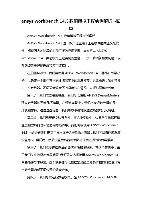
Calculate a solution
Modify solution parameters or grid
Check for convergence
Yes
No
Check for accuracy
No
Yes Stop
A Pera Global Company © PERA China
求解器选择
中有两种求解器 – 压力基和密 度基。
求解过程概览
求解参数 选择求解器 离散格式 初始条件 收敛 监测收敛过程 稳定性 设置松弛因子 设置 加速收敛 精度 网格无关性 自适应网格
Set the solution parameters
Initialize the solution
Enable the solution monitors of interest
启动 初始化 压力基求解器: 密度基求解器: 当选择密度基求解器后在 里可见
在粗网格上用多重网格求解 通过 命令来设置
A Pera Global Company © PERA China
培训教材 第四节:求解器设置
A Pera Global Company © PERA China
概要
使用求解器(求解过程概览) 设置求解器参数 收敛 定义 监测 稳定性 加速收敛 精度 网格无关性 网格自适应 非稳态流模拟(后续章节中介绍) 非稳态流问题设置 非稳态流模型选择 总结 附录
A Pera Global Company © PERA China
初始化
要求所有的求解变量有初始 值
更真实的初值能提高收敛稳 定性,加速收敛过程.
有些情况需要一个好的初值
在特定区域对特定变量单独 赋值
Fluent 资料集合(续)

流体动力学的并行计算(EN)
流体动力学的有限元法(EN) 流体动力学的有限元法(卷3)(EN) 流体动力学和流体机械手册卷1(EN)
10.Fluent动网格教程分享
fluent动荡讲座
fluent动态网讲座 fluent动态网教程1—8
11.Fluent软件知多少
相当水力直径进行计算?
A:1.如果不画边界层的计算结果与实验值的误差在工程精度范围内,是 可以接受的;但是,正如贴主所说,有边界层算的更准,那保证网格质 量就没有多大意义了。 2.如果不画边界层网格,建议采用k-epsilon Realizable湍流模型。
3.计算水力直径,应当是计算域流体入口的水力直径:H=4A/C(A为入口
7.2014 ANSYS技术大会讲义集--系统
ANSYS SBU视觉从三维到嵌入式软件 UGM V2
Ansys_基于模型的系统和软件工程_傅金泉_v2.0
UGM V1的SCADE创新 先进的UGM V7系统设计 张国明-云时代的中国仿真 - 2014 ANSYS中国UGM演讲V2
8.FLUENT超级学习手册
Fluent 14.5 Eulerian Wall Film Defogging官方教程
Fluent 14.5自定义输入参数官方教程
Fluent_14.5meshing官方教程 Fluent 14.5 FSI官方教程 Fluent 14.5 built-in tutorials Fluent 14.5传热 官方教程
3.之前利用fluent计算敞水时舵的水动力,采用SST湍流模型,分别用有
边界层和无边界层进行计算,无边界层计算的升力、阻力比有边界层的 大10%左右,有边界层更接近实验值。不过失速角和变化趋势还是一致的
ANSYS FLUENT培训教材之求解器设置

路漫漫其修远兮, 吾将上下而求索
压力速度耦合
压力基求解器通过连续性方程和动量方程导出压力方程或压力修 正方程
FLUENT中有四种耦合方式
– Semi-Implicit Method for Pressure-Linked Equations (SIMPLE)
• 默认算法,稳健性好
– SIMPLE-Consistent (SIMPLEC)
隐式方法一般优于显式,因为其对时间步有严格的限制 显式方法一般用于流动时间尺度和声学时间尺度相当的情况(如高马
赫激波的传播)
路漫漫其修远兮, 吾将上下而求索
离散化(插值方法)
存储在单元中心的流场变量必须插值到控制体面上
对流项的插值方法有: – First-Order Upwind – 易收敛,一阶精度。 – Power Law –对低雷诺数流动 ( Recell < 5 )比一阶格式更精确 – Second-Order Upwind – 尤其适用流动和网格方向不一致的四面体/三 角形网格,二阶精度,收敛慢 – Monotone Upstream-Centered Schemes for Conservation Laws (MUSCL) – 对非结构网格,局部三阶精度,对二次流、旋转涡、力等 预测的更精确 – Quadratic Upwind Interpolation (QUICK) – 适用于四边形/六面体以及 混合网格,对旋转流动有用,在均匀网格上能达到三阶精度
Initialize the solution
Enable the solution monitors of interest
Calculate a solution
Modify solution parameters or grid
ANSYS FLUENT 14.5 Population Balance Module Manual

ANSYS, Inc. Southpointe 275 Technology Drive Canonsburg, PA 15317 ansysinfo@ (T) 724-746-3304 (F) 724-514-9494
Table of Contents
Using This Manual ........................................................................................................................................ v 1. The Contents of This Manual ................................................................................................................ v 2. The Contents of the FLUENT Manuals ................................................................................................... v 3. Typographical Conventions ................................................................................................................. vi 4. Mathematical Conventions ........
关于FLUENT Adjoint伴随求解器的用法

关于伴随求解器伴随求解器的思路:(1)首先算初始流场,算到完全收敛为止。
如果不收敛的话,在做adjoint敏感性分析的时候可能不准,而且进一步计算会受不收敛流场的影响,导致难以判断(2)然后转入激活伴随求解器正常的话会在下拉菜单里面看到多出了伴随求解器的选项。
(3)然后开始设置伴随求解器的目标observables,在create的时候会发现一系列的目标选项,有直接的物理量也有通过运算得到的物理量。
比如受力,力矩,旋流,压降,固定值,表面积分再比如比率,产量,线性组合,算术平均,平均变差(均匀性),一元操作关系这样创建变量类型之后就可以定义其最大最小值了,并直接评估初始流场里面关于这个目标值的初始情况。
注意不同的目标变量类型对应后面定义的时候设置也是不同的。
(4)定义好目标变量及其类型之后就转入伴随求解器的定义,最新的V15里面对这个地方进行了改进,可以指定流场求解器和伴随求解器各自的计算格式。
(5)然后转入求解器控制页面,一般用默认的设置就可以了。
(6)然后设定监控,最好手动点一下plot。
然后就可以开始运行计算了。
(7)计算完成之后有一个numerical scenarios数值探索,可以选择别的不同的算法试一下。
进一步提升敏感性计算的精度。
(8)然后转入report页面,通过初步计算的形式反映和目标有相关性的边界对目标值的敏感性贡献。
(9)然后通过后处理云图和矢量箭头显示敏感性因子。
(10)然后就可以转入控制体设定阶段。
控制体设好之后一定要点一下update更新设定,这样左下角的变形控制才能激活。
关于scale factor的设定,这个设定是控制变形量的,当然这个变形量就直接关系到目标的变化,因此,可以试点一下expected change这个按钮,通过GUI打印出来的目标值变化测试scale factor 这个值是往大的变还是往小的变,所以正负这些,大于1还是小于1这些都不一定。
要观察实际目标变量的变化。
ansys workbench 14.5数值模拟工程实例解析 -回复
ansys workbench 14.5数值模拟工程实例解析-回复ANSYS Workbench 14.5 数值模拟工程实例解析ANSYS Workbench 14.5是一款广泛应用于工程领域的数值模拟软件,拥有强大的计算能力和广泛的应用范围。
本文将以ANSYS Workbench 14.5数值模拟工程实例为主题,一步一步回答相关问题,以帮助读者更好地理解和应用该软件。
在工程实例中,我们将使用ANSYS Workbench 14.5进行热传导分析,以确定一个组件在不同环境温度下的温度分布。
具体来说,我们将分析一个散热器在不同环境温度下的温度分布情况,以评估其散热性能。
第一步,我们需要准备模型。
我们可以使用ANSYS DesignModeler 建立散热器的三维几何模型。
在设计模型中,我们将考虑散热器的尺寸、形状和材料。
通过这些信息,我们可以准确地描述散热器的几何特征。
第二步,我们需要定义边界条件。
在这个实例中,边界条件包括环境温度和散热器与环境之间的热传导。
我们可以使用ANSYS Workbench 14.5中的边界条件定义工具来设置这些参数。
例如,我们可以将环境温度设置为25摄氏度,然后设置散热器的表面与环境之间的热传导系数。
第三步,我们需要选择适当的数值方法和求解器。
在这个实例中,由于我们关注的是热传导问题,我们可以选择使用ANSYS Workbench 14.5中的热传导求解器。
这个求解器可以根据定义的边界条件和材料属性计算出散热器内部不同位置的温度分布。
第四步,我们可以运行数值模拟。
在ANSYS Workbench 14.5中,我们可以使用流程导航器来设置和运行数值模拟过程。
在这个实例中,我们可以选择模拟和后处理选项,然后点击运行按钮开始数值模拟。
在实际运行过程中,ANSYS Workbench 14.5将自动进行网格生成、有限元分析和结果后处理等步骤。
第五步,我们可以进行结果分析和可视化。
ANSYSFLUENT介绍
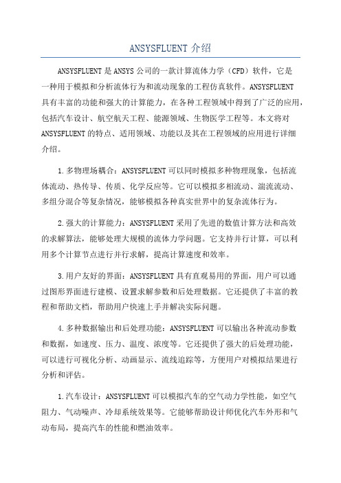
ANSYSFLUENT介绍ANSYSFLUENT是ANSYS公司的一款计算流体力学(CFD)软件,它是一种用于模拟和分析流体行为和流动现象的工程仿真软件。
ANSYSFLUENT具有丰富的功能和强大的计算能力,在各种工程领域中得到了广泛的应用,包括汽车设计、航空航天工程、能源领域、生物医学工程等。
本文将对ANSYSFLUENT的特点、适用领域、功能以及其在工程领域的应用进行详细介绍。
1.多物理场耦合:ANSYSFLUENT可以同时模拟多种物理现象,包括流体流动、热传导、传质、化学反应等。
它可以模拟多相流动、湍流流动、多组分混合等复杂情况,能够模拟各种真实世界中的复杂流体行为。
2.强大的计算能力:ANSYSFLUENT采用了先进的数值计算方法和高效的求解算法,能够处理大规模的流体力学问题。
它支持并行计算,可以利用多个计算节点进行并行求解,提高计算速度和效率。
3.用户友好的界面:ANSYSFLUENT具有直观易用的界面,用户可以通过图形界面进行建模、设置求解参数和后处理数据。
它还提供了丰富的教程和帮助文档,帮助用户快速上手并解决实际问题。
4.多种数据输出和后处理功能:ANSYSFLUENT可以输出各种流动参数和数据,如速度、压力、温度、浓度等。
它还提供了强大的后处理功能,可以进行可视化分析、动画显示、流线追踪等,方便用户对模拟结果进行分析和评估。
1.汽车设计:ANSYSFLUENT可以模拟汽车的空气动力学性能,如空气阻力、气动噪声、冷却系统效果等。
它能够帮助设计师优化汽车外形和气动布局,提高汽车的性能和燃油效率。
2.航空航天工程:ANSYSFLUENT可以模拟飞机、火箭等飞行器的气动特性,如升力、阻力、空气动力学热效应等。
它可以帮助航空航天工程师优化飞行器的设计,提高飞行器的性能和安全性。
3.能源领域:ANSYSFLUENT可以模拟火力发电厂、核电站、风力发电机等能源设备的热流体特性,如燃烧过程、热传导、流动分布等。
ansys workbench 14.5数值模拟工程实例解析 -回复

ansys workbench 14.5数值模拟工程实例解析-回复问题的提出:ANSYS是目前世界上使用最广泛的CAE(计算机辅助工程)软件之一。
ANSYS Workbench 14.5是ANSYS公司最新发布的版本,拥有强大的数值模拟功能。
本文将以ANSYS Workbench 14.5数值模拟工程实例为基础,一步一步解析其过程和结果。
第一步:了解数值模拟工程的概念和作用数值模拟工程是指使用数值计算方法对工程问题进行模拟和求解的过程。
通过数学模型的构建和数值方法的运算,可以预测工程系统的行为,优化设计,并降低实际试验的成本。
数值模拟工程在航空航天、汽车工程、建筑工程等领域具有广泛的应用。
第二步:准备实验模型和边界条件在本次实例中,我们选择了一个简单的结构力学问题作为例子。
假设我们要研究一个悬臂梁的应力分布情况。
悬臂梁的几何形状、材料性质和加载条件都需要在ANSYS Workbench中进行定义和设置。
通过准备实验模型和边界条件,可以模拟出各种不同的工程问题。
第三步:网格划分和离散化网格划分是数值模拟中非常重要的一步,它将实际工程问题的连续域划分成离散域,以便于计算机进行数值计算。
在本次实例中,我们可以使用ANSYS Workbench提供的自动网格划分工具,将悬臂梁的几何形状离散为小的单元。
划分的单元越小,计算结果越准确,但计算量也会增加。
第四步:施加加载条件和求解在悬臂梁的数值模拟中,需要选择适当的加载条件来模拟实际工况。
例如,我们可以施加一个集中力作用在悬臂梁的端点处。
通过ANSYS Workbench提供的加载条件设置功能,可以灵活地模拟不同的加载情况。
同时,我们需要选择适当的求解方法和求解器进行计算。
在这个阶段,我们可以点击“求解”按钮,开始计算。
第五步:结果分析和后处理当计算完成后,我们可以对结果进行分析和后处理。
通过ANSYS Workbench提供的可视化工具,可以直观地展示应力、变形、流动等结果。
- 1、下载文档前请自行甄别文档内容的完整性,平台不提供额外的编辑、内容补充、找答案等附加服务。
- 2、"仅部分预览"的文档,不可在线预览部分如存在完整性等问题,可反馈申请退款(可完整预览的文档不适用该条件!)。
- 3、如文档侵犯您的权益,请联系客服反馈,我们会尽快为您处理(人工客服工作时间:9:00-18:30)。
ANSYS FLUENT Meshing Text Command List Release 14.5ANSYS, Inc.October 2012Southpointe275 Technology Drive Canonsburg, PA 15317ANSYS, Inc. is certified to ISO 9001:2008.ansysinfo@(T) 724-746-3304(F) 724-514-9494Copyright and Trademark Information© 2012 SAS IP, Inc. All rights reserved. Unauthorized use, distribution or duplication is prohibited.ANSYS, ANSYS Workbench, Ansoft, AUTODYN, EKM, Engineering Knowledge Manager, CFX, FLUENT, HFSS and any and all ANSYS, Inc. brand, product, service and feature names, logos and slogans are registered trademarks or trademarks of ANSYS, Inc. or its subsidiaries in the United States or other countries. ICEM CFD is a trademark used by ANSYS, Inc. under license. CFX is a trademark of Sony Corporation in Japan. All other brand, product, serviceand feature names or trademarks are the property of their respective owners.Disclaimer NoticeTHIS ANSYS SOFTWARE PRODUCT AND PROGRAM DOCUMENTATION INCLUDE TRADE SECRETS AND ARE CONFID-ENTIAL AND PROPRIETARY PRODUCTS OF ANSYS, INC., ITS SUBSIDIARIES, OR LICENSORS.The software productsand documentation are furnished by ANSYS, Inc., its subsidiaries, or affiliates under a software license agreement that contains provisions concerning non-disclosure, copying, length and nature of use, compliance with exporting laws, warranties, disclaimers, limitations of liability, and remedies, and other provisions.The software productsand documentation may be used, disclosed, transferred, or copied only in accordance with the terms and conditions of that software license agreement.ANSYS, Inc. is certified to ISO 9001:2008.U.S. Government RightsFor U.S. Government users, except as specifically granted by the ANSYS, Inc. software license agreement, the use, duplication, or disclosure by the United States Government is subject to restrictions stated in the ANSYS, Inc. software license agreement and FAR 12.212 (for non-DOD licenses).Third-Party SoftwareSee the legal information in the product help files for the complete Legal Notice for ANSYS proprietary software and third-party software. If you are unable to access the Legal Notice, please contact ANSYS, Inc.Published in the U.S.A.Table of Contents1.Text Menu System (1)2. boundary/ (3)3. display/ (23)4. exit (39)5. file/ (41)6. material-point/ (47)7. mesh/ (49)8. objects/ (75)9. parallel/ (79)10. report/ (81)11. size-functions/ (83)12. switch-to-solution-mode (85)iiiRelease 14.5 - © SAS IP, Inc. All rights reserved. - Contains proprietary and confidential information of ANSYS, Inc. and its subsidiaries and affiliates.Release 14.5 - © SAS IP, Inc. All rights reserved. - Contains proprietary and confidential information ivof ANSYS, Inc. and its subsidiaries and affiliates.Chapter 1:Text Menu SystemThe TGrid user interface consists of a textual command line reference.The text user interface (TUI) is written in a dialect of Lisp called Scheme. Users familiar with Scheme will be able to use the interpretive capabilities of the interface to create customized commands.The text menu system provides a hierarchical interface to the underlying procedural interface of the program.•You can easily manipulate its operation with standard text-based tools—input can be saved in files,modified using text editors, and read back in to be executed, because it is text based.•The text menu system is tightly integrated with the Scheme extension language, so it can easily be pro-grammed to provide sophisticated control and customized functionality.The menu system structure is similar to the directory tree structure of UNIX operating systems.When you first start TGrid you are in the “root" menu and the menu prompt is simply a caret:>To generate a listing of the submenus and commands in the current menu, press Enter .>boundary/ exit mesh/display/ file/ report/By convention, submenu names end with a / to differentiate them from menu commands.To execute a command, type its name (or an abbreviation). Similarly, to move down into a submenu, enter its name or an abbreviation.When you move into the submenu, the prompt will change to reflect the current menu name.> display/display > set/display/set >To move back to the previously occupied menu, type q or quit at the prompt./display/set > q/display >You can move directly to a menu by giving its full pathname./display > /file/display//file >In the above example, control was passed from /display to /file without stopping in the root menu.Therefore, when you quit from the /file menu, control will be passed directly back to /dis-play .1Release 14.5 - © SAS IP, Inc. All rights reserved. - Contains proprietary and confidential information of ANSYS, Inc. and its subsidiaries and affiliates.Text Menu System/display//file > q/display >If you execute a command without stopping in any of the menus along the way, control will again be returned to the menu from which you invoked the command./display > /file start-journal jrnlOpening input journal to file "jrnl"./display >Release 14.5 - © SAS IP, Inc. All rights reserved. - Contains proprietary and confidential informationof ANSYS, Inc. and its subsidiaries and affiliates.2Chapter 2: boundary/auto-slit-facesslits all boundary faces with cells on both sides (these cells must be in the same cell zone). A displacement can be specified to provide thickness to the boundary.boundary-conditions/contains options for copying or clearing boundary conditions when a case file is read.clearclears the boundary conditions assigned to the specified face zones.clear-allclears the boundary conditions assigned to all the face zones.copyallows you to copy the boundary conditions from the face zone selected to the face zones specified.check-boundary-meshreports the number of Delaunay violations on the triangular surface mesh and the number of isolated nodes.check-duplicate-geomdisplays the names of the duplicate surfaces and prints maximum and average distance between them.clear-marked-facesclears marked faces.clear-marked-nodesclears nodes that were marked using the mark-duplicate-nodes command.compute-bounding-boxcomputes the bounding box for the zones specified.count-free-nodesreports the number of boundary nodes associated with edges having only one attached face.count-marked-facesreports the number of marked faces.count-unused-bound-nodecounts the unused boundary nodes in the domain.count-unused-faceslists the number of boundary faces that are not used by any cell.count-unused-nodes lists the number of boundary nodes that are not used by any cell.3Release 14.5 - © SAS IP, Inc. All rights reserved. - Contains proprietary and confidential information of ANSYS, Inc. and its subsidiaries and affiliates.boundary/create-bounding-boxallows you to create the bounding box for the specified zones.create-cylinderallows you to create a cylinder by specifying the two axis end nodes or positions, by specifying three points on the arc defining the cylinder, or by specifying three points on the arc defining the cylinder and a height node.create-plane-surfaceallows you to create a plane surface by specifying either the axis direction, axial location, and the extents of the surface or three points defining the plane.create-swept-surfaceallows you to create a surface by sweeping the specified edge in the direction specified.delete-all-dup-facessearches for faces on all boundary zones that have the same nodes and deletes the duplicates.delete-duplicate-facessearches for faces on a specified zone that have the same nodes and deletes the duplicates.Duplicate faces may be present if you generated the boundary mesh using a third-party grid gener-ator, or if you have used the slit-boundary-face command to modify the boundary meshand then merged the nodes.delete-free-edge-facesallows you to remove faces with the specified number of free edges from the specified boundary zones. delete-island-facesallows you to delete faces in a non-contiguous region of a face zone.delete-unconnected-facesallows you to delete the unconnected face-zones.delete-unused-facesdeletes all the boundary faces that are not used by any cell.delete-unused-nodesdeletes the boundary nodes that are not used by any boundary faces.edge-limitsprints the length of the shortest and longest edges on the boundary.This information is useful for setting initial mesh parameters and refinement controls.face-distributionreports the distribution of face quality in the text window.face-skewnesslists the worst face skewness.feature/allows you to create and modify features.copy-edge-zonescopies the specified edge zone(s) to new edge zone(s).Release 14.5 - © SAS IP, Inc. All rights reserved. - Contains proprietary and confidential information4of ANSYS, Inc. and its subsidiaries and affiliates.create-edge-zonesextracts edge loops for the specified face zone(s) based on the feature method specified.You also need to specify an appropriate value for feature angle when using the fixed-angle method.NoteThe Face Seed approach cannot be used when creating edge loops using text com-mands.delete-edge-zonesdeletes the specified edge zone(s)edge-size-limitsreports the minimum, maximum, and average edge length for the specified edge zone(s) in the console.groupassociates the specified edge zone(s) with the specified face zone.intersect-edge-zonesintersects the specified edge loops to create a new edge loop comprising the common edges.You can enable automatic deleting of overlapped edges and specify an appropriate intersection tolerance.list-edge-zoneslists the name, ID, type, and count for the specified edge zone(s).merge-edge-zonesmerges multiple edge loops of the same type into a single loop.orient-edge-directionorients the edges on the loop to point in the same direction.project-edge-zonesprojects the edges of the specified loop onto the specified face zone using the specified projection method.remesh-edge-zonesremeshes the specified edge loop(s), modifying the node distribution according to the specified remeshing method, spacing values, and feature angle.You can also enable quadratic reconstruction,if required.reverse-edge-directionreverses the direction of the edge loop.separate-delete-small-edgesseparates the edge zones based on the feature angle specified, and then deletes the edges having a count smaller than the minimum count specified.separate-edge-zonesseparates the specified edge loop based on connectivity and the specified feature angle.toggle-edge-type toggles the edge type between boundary and interior.5Release 14.5 - © SAS IP, Inc. All rights reserved. - Contains proprietary and confidential information of ANSYS, Inc. and its subsidiaries and affiliates.boundary/ungroupungroups previously grouped edge zones.fix-mconnected-edgesresolves multi-connected edges/non-manifold configurations in the boundary mesh by deleting fringes and overlaps based on threshold values specified.improve/allows you to improve boundary surfaces.collapse-bad-facesallows you to collapse the short edge of faces having a high aspect ratio or skewness in the specified face zone(s).degree-swapallows you to improve the boundary mesh by swapping edges based on a node degree value other than 6.The node degree is defined as the number of edges connected to the node.improveallows you to improve the boundary surface quality using skewness, size change, aspect ratio, orarea as the quality measure.smoothallows you to improve the boundary surface using smoothing.swapallows you to improve the boundary surface using edge swapping.jiggle-boundary-nodesrandomly perturbs all boundary nodes based on an input tolerance. Some nodes will be perturbed less than the tolerance value, while others will be perturbed by half of the tolerance value in all three co-ordinate directions.make-periodicprompts first for the type of periodicity and then, if rotational, the angle and axis of rotation, or, iftranslational, the translational shift. Specify the boundary zones to be made periodic. A corresponding periodic shadow boundary zone will be created for each of these zones.manage/contains options for manipulating the boundary zones.auto-delete-nodes?specifies whether or not unused nodes should be deleted when their face zone is deleted.change-prefixallows you to change the prefix for the specified face zones.copycopies all nodes and faces of the specified face zone(s).createcreates a new face zone.deletedeletes the face zone.Release 14.5 - © SAS IP, Inc. All rights reserved. - Contains proprietary and confidential information6of ANSYS, Inc. and its subsidiaries and affiliates.flipreverses the normal direction of the specified boundary zone(s).idspecifies a new boundary zone ID. If there is a conflict, the change will be ignored.listprints information about all boundary zones.mergemerge face zones.namegives a face zone a new name.orientconsistently orients the faces in the specified zones.originspecifies a new origin for the mesh, to be used for face zone rotation and for periodic zone creation.The default origin is (0,0,0).rotaterotates all nodes of the specified face zone(s).scalescales all nodes of the specified face zone(s).translatetranslates all nodes of the specified face zone(s).typechanges the boundary type and name of the face zone.user-defined-groupsallows you to manipulate user-defined groups.activateactivates the specified user-defined groups.createcreates the user-defined group comprising the specified zones.deletedeletes the specified user-defined group.listlists the groups in the console.updateallows you to modify an existing group.boundary/mark-duplicate-nodesmarks duplicate nodes.The marked nodes will appear in the grid display when nodes are displayed. Fora list of duplicate nodes, set the /report/verbosity level to 2 before using the mark-duplicate-nodes command.mark-face-intersectionmarks intersecting faces. Intersection is detected if the line defined by any two consecutive nodes on a face intersects any face in the current domain.The marked faces will appear in the grid display when faces are displayed. For a list of intersecting faces, set the /report/verbosity level to 2 before using the mark-face-intersection command.mark-face-proximitymarks faces that are in proximity to each other.Face A is considered to be in proximity to face B if any of the nodes on face A are within the calcu-lated proximity distance from face B.The proximity distance is calculated based on the specifiedrelative distance and the sphere radius.The sphere radius is determined by the maximum distance from the centroid of the face to its nodes.The marked faces will appear in the grid display whenfaces are displayed.For a list of faces in proximity to each other, set the/report/verbosity level to 2 before using the mark-face-proximity command.mark-faces-in-regionmarks the faces that are contained in a specified local refinement region.merge-nodesmerges duplicate nodes.merge-small-face-zonesmerges the face zones having area less than the minimum area.modify/discusses the commands used to modify the boundary mesh.analyze-bnd-connectvtyfinds and marks free edges and nodes and multiply-connected edges and nodes.This process isnecessary if the boundary mesh has been changed with Scheme functions.auto-redisplaytoggles the automatic redisplay of the modified mesh.clear-selectionsclears all selections.clear-skew-facesclears faces that were marked using the mark-skew-face command.collapsecollapses pairs of nodes, edge(s), or face(s). If a pair of nodes is selected, both the nodes are deleted and a new node is created at the midpoint of the two nodes. If a triangular face is selected, thecomplete face is collapsed into a single node at the centroid of the face.Save the boundary mesh before performing this operation because collapsing is not reversible(i.e., you cannot undo a collapse operation).createcreates a boundary face if the selection list contains 3 nodes and an optional zone. If the selection list contains positions, then nodes are created.create-mid-nodecreates a node at the midpoint between two selected nodes.deletedeletes all selected faces and nodes.delta-moveallows you to move the selected node by specified magnitude.deselect-lastremoves the last selection from the selection list.hole-feature-angleallows you to specify the feature angle for consideration of holes in the geometry.list-selectionslists all of the selected objects.mark-skew-facemarks faces that should be skipped when the worst skewed face is reported using the ModifyBoundary dialog box.This allows you to search for the next skewed face.mergemerges pairs of nodes.The first node selected is retained, and the second is the duplicate that is merged.movemoves the selected node to the selected position if the selection list contains a node and a position. next-skewfinds the triangular face of nearest lower skewness value than that of the worst skewed face.The face ID, its skewness, the longest edge ID, and the node ID opposite to the longest edge are displayed in the console.repairrepairs the selected zone(s) by filling all holes associated with free edges.rezonemoves the selected faces from their current zone into the selected zone, if the selection list containsa zone and one or more faces.select-entityallows you to add a cell, face, or node to the selection list by entering the name of the entity.select-filterselects a filter.The possible filters are off,cell,face,edge,node,zone, and position. If off is chosen, then when a selection is made, it is first checked to see if it is a cell, then a face, an edge,boundary/and so on.When the node filter is used, and if a cell or face is selected, the node closest to the se-lection point is picked.Thus, the nodes do not have to be displayed, to be picked.select-positionallows you to add a position to the selection list by entering the coordinates of the position.select-probeselects the probe function.The possible functions are:•box enables the selection of a group of entities within a box, to be used in conjunction withboundary modification functions.•label prints the selection label in the graphics window•off disables the mouse probes.•polygon enables the selection of a group of entities within a polygonal region, to be used inconjunction with boundary modification functions.•print prints the information on the selection in the console window.•select adds the selection to the selection listselect-zoneallows you to add a zone to the selection list by entering the zone name or ID.show-filtershows the current filter.show-probeshows the current probe function.skewfinds the face with the highest (worst) skewness, selects it in the graphics window, and reports itsskewness and zone ID in the console window.skew-report-zoneallows you to select the zone for which you want to report the skewness.You can either specifyzone name or zone ID.smoothuses Laplace smoothing to modify the position of the nodes in the selection list. It moves the selected node to a position computed from an average of its node neighbors.The new position is an average of the neighboring node coordinates and is not reprojected to the discrete surface.split-facesplits two selected faces into four faces.swapswaps boundary edges (of triangular faces) if the selection list contains edges.undoundoes the previous operation.When an operation is performed, the reverse operation is stored on the undo stack. For example, a create operation places a delete on the stack, and a delete adds acreate operation.The only exception is merge, which cannot be undone.Theoretically if no merge operations areperformed, you could undo all previous operations. In reality, certain sequences of operationsare not reversible.The undo operation requires that the name of the object exist when the action is undone. Ifthe name does not exist, then the undo will fail.You can undo the last few operations, but ifmany operations are being performed it is recommended that you also save the mesh periodically,particularly before merge operations.orient-faces-by-pointorients the normals based on the specified material point.print-infoprints information about the grid in the text window.project-face-zoneallows nodes on a selected face zone to be projected onto a target face zone. Projection can be performed based on normal direction, closest point, or specified direction.refine/discusses the commands used to refine the boundary mesh.auto-refineautomatically refines a face zone based on proximity.The original face zone is treated as a background mesh. Faces are refined by multiple face splitting passes, so that no face is in close proximity to anyface in the current domain.clearclears all refinement marks from all boundary faces.countcounts the number of faces marked on each boundary zone.limitsprints a report of the minimum and maximum size of each specified zone.This report will also tellyou how many faces on each zone have been marked for refinement.local-regionsenters the local refinement menu.definedefines the refinement region according to the specified parameters.deletedeletes the specified region.initcreates a region encompassing the entire geometry.list-all-regionslists all the refinement regions in the console.markmarks the faces for refinement.boundary/refinerefines the marked faces.remesh/has a set of commands that allows you to remesh the face zones.clear-marked-facesclears the highlighting of the triangles that are marked.controls/enters the edge loop tools text menu.delete-overlapped?toggles the deletion of region of overlap of the two surfaces.directionspecifies the direction of the edge loop projection.intersect/enters the intersect control menu.absolute-tolerance?allows you to switch between the use of absolute and relative tolerance. By default, the rel-ative tolerance value is used.delete-overlap?enables/disables the deletion of overlapped edges. It toggles the automatic deletion of regionof overlap of the two surfaces.This option is used by while remeshing overlapping zonesand retriangulating prisms. By default, this option is enabled.feature-angleallows you to specify the minimum feature angle that should be considered while retriangu-lating the boundary zones.join-match-anglespecifies the allowed maximum angle between the normals of the two overlapping surfacesto be joined.This parameter is used to control the size of the join region.refine-region?allows you to refine the regions that are modified during the intersect operations. It togglesthe refinement of the intersecting regions after performing any of the intersection operation.This operation improves the quality of the resulting mesh, however, this option is disabledby default.retri-improve?allows you to improve the mesh. After performing any intersection operation, the slivers areremoved along the curve of intersection, Laplace smoothing is performed, and followed bythe edge swapping. Laplace smoothing is also performed for insert-edge-zone,remesh-overlapped-zones, and prism-retriangulation options. Smoothing is performedagain.The smooth-swap operations can be controlled by changing the various defaults suchas swapping iterations, smoothing iterations, etc.separate?toggles the automatic separation of intersected zones.stitch-preserve?indicates that the geometry and location of the intersect zone (the zone in the left GUI zonelist) is to be preserved.This option is enabled by default.toleranceallows you to specify the tolerance value.within-tolerance?performs the intersection operation only within the specified tolerance value. It is useful onlyfor the Intersect option.project-methodspecifies the method for projecting edge loops.proximity-local-search?includes the selected face for proximity calculation.quadratic-recon?enables/disables quadratic reconstruction of edge loops.remesh-methodspecifies the method to be used for the node distribution on the edge loop.spacingsets the node spacing for the edge loop.tolerancesets the tolerance for determining if two edges intersect.create-all-intrst-loopscreates edge loop of intersection for all boundary zones in current domain.create-edge-loopscreates edge loops for a specified face zone, based on feature angle.create-intersect-loopcreates an interior edge loop at the intersection between two adjacent face zones. Edges created in this way will not be remeshed by default.create-join-loopcreates edge loop on boundary of the region of overlap of two surfaces.create-stitch-loopcreates edge loops for connecting two surfaces along their free edges.delete-overlapped-edgesdeletes edges that overlap selected edge loops.faceted-stitch-zonesallows you to perform the faceted stitching of zones.boundary/insert-edge-zoneallows you to insert an edge zone into a triangulated boundary face zone.intersect-all-face-zonesallows you to intersect all the face zones.intersect-face-zonesremeshes two intersecting face zones so that they become conformal.join-all-face-zonesallows you to join all face zones.join-face-zonesallows you to connect two overlapping faces.mark-intersecting-faceshighlights the triangles in the neighborhood of the line of intersection.mark-join-faceshighlights the triangles in the neighborhood of the join edge loop.mark-stitch-faceshighlights the triangles in the neighborhood of the stitch edge loop.remesh-face-zoneremeshes a specified face zone by automatically extracting edge loops. If edge loops are present in the current domain (e.g., if they were created using the create-edge-loops command), they are used to remesh the specified face zone.remesh-overlapping-zonesremeshes overlapping face zones.The non-overlapping region is remeshed using the edge loops created from the overlapping face zones.size-functionsenters the size functions menu where you can define size functions for controlling mesh size distri-bution.createdefines the size function based on the specified parameters.create-defaultscreates default size functions based on face and edge curvature and proximity.deletedeletes the specified size function.delete-alldeletes all the defined size functions.listlists all the defined size functions and the parameter values defined.resetallows you to reset the size function background grid in order to have the mesh distribution re-computed based on all defined size functions.。