XPL-ds_ Xenus Copley交流伺服驱动器
星辰伺服驱动说明书
NAS 系列交流伺服系统使用说明书特别提示在您第一次接通本伺服系统电源以前,为确保系统能安全、正常、高效地为您工作,请仔细阅读手册中有关使用方面的重要信息。
感谢使用星辰伺服的交流伺服系统!为使本机一直维持良好的运行状态,请将本手册随整机附送给最终用户。
虽然在您的选型过程中,可能已经对本产品有所了解并与本公司的技术人员进行了某些沟通,但为充分发挥本机最佳功能,仍请在使用前,仔细阅读本使用说明书,必要时可与星辰伺服的有关人员联系以获得必要的帮助。
本说明书中,对不同级别的提示、警示、警告采用如下提示符:★一般性的提示警示,如果不按照执行,可能带来设备的损坏警告,如果不按照执行可能带来设备严重损坏、火灾或人身伤害星辰伺服分支机构及技术服务机构:桂林星辰电力电子有限公司市场服务部地址:桂林高新技术产业开发区星辰大厦邮编:541004电话:************,5810692 传真:************ Email:******************上海星之辰电气传动技术有限公司伺服部地址:上海市科技创业中心(徐汇区钦州路100号)2#601-605 邮编:200235电话:************(8线), 64829055 传真:************深圳市星辰激光技术有限公司伺服部地址:深圳市高新区北区清华信息港研发楼A栋3楼邮编:518057电话:*************(15线),26030572 传真:*************目录1.安全注意事项1.1.安装注意事项1.2.运转操作注意事项1.3.保养检查注意事项1.4.关于废弃1.5.其它2.产品的确认和注意事项2.1.产品的确认2.2.伺服电机型号说明2.3.伺服驱动器型号说明2.4.使用前的注意事项3.NAS系列交流伺服系统性能参数3.1.NAS系列伺服系统标准规格配套表3.2.驱动器标准规格及功能表3.2.1.驱动器标准规格及一般功能3.2.2.驱动器使用环境条件及一般技术状态3.2.3.驱动器控制功能及运动性能表3.2.4.伺服电机特性3.2.4.1.N系列电机3.2.4.2.SY系列电机3.2.5.有关工作制的说明4.安装4.1.安装场所和保养4.2.驱动器外形尺寸4.3.驱动器安装4.4.驱动器前级盒的拆卸和安装4.5.伺服电机外形尺寸4.6.伺服电机安装4.7.制动电阻安装5.端口说明及外围电路设计5.1.接线注意事项5.2.外围接线图及端口说明5.2.1.控制接口(44芯排插头)全部功能连接图5.2.2.控制接口(44芯排插头)接口功能表5.2.3.状态通报口的使用5.2.4.模拟量接口的使用5.2.5.转矩环控制运行5.2.6.速度环控制运行5.2.7.带速度限制的位置环控制运行5.2.8.带转矩限制的位置环控制运行5.2.9.带转矩限制的速度环控制运行5.2.10.带转矩偏置的速度环控制运行5.2.11.位置环脉冲给定接口的使用5.2.12.反馈接口(15芯排插头)的连接5.2.13.反馈接口(15芯排插头)端口功能表5.2.14. RS485接口(9芯排插头)的连接5.2.15. RS485接口(9芯排插头)端口功能表5.2.16.动力接口6.操作面板6.1.面板显示说明6.1.1.监视状态下驱动器面板显示状态表6.1.2.运行状态下驱动器面板显示状态表6.2.面板操作说明及编辑状态下面板显示6.2.1.几种典型的操作6.2.2.编辑状态下的显示7.运转7.1.运转前的检查7.2.首次上电和试运转7.3.运转7.3.1.功能、参数设定总表7.3.2.位置闭环运行7.3.3.速度闭环运行7.3.4.转矩环运行8.RS485串行通讯功能8.1.概述8.2.通过RS485串行通讯进行伺服驱动器的运转8.2.1.状态查询8.2.2.修改参数8.2.3.实时控制8.3.TB485-V10通讯协议8.3.1.串口通讯数据格式8.3.2.工作方式说明8.3.2.1.问答方式8.3.2.2.速传方式8.3.3.通讯故障约定及校验说明8.3.3.1.问答方式8.3.3.2.速传方式9.保护功能9.1.设定方法(功能代码显示模式)9.2.功能代码一览表9.3.功能说明10.故障确认11.保养和检查11.1.保养和检查时的注意事项11.2.检查项目11.3.兆欧表测试11.4.零部件的更换安全注意事项1.安全注意事项1.1.安装注意事项★ 安装环境:使用温度伺服电机 -20℃~+40℃伺服驱动器 -10℃~+40℃保存温度-25℃~+65℃环境湿热伺服电机 95%,30℃,不结露伺服驱动器 90%,30℃,不结露标准高度海拔2000m以下(2000m以上,每上升1000m降容20%)★ 请将电机和驱动器安装于通风良好的场所。
伺服驱动器_原理_概述及解释说明

伺服驱动器原理概述及解释说明1. 引言1.1 概述伺服驱动器作为一种关键的控制设备,在现代工业中发挥着重要的作用。
它主要用于控制电机和执行器的运动,通过实时监测和调整输出信号,使得目标位置或速度可以精确控制。
伺服驱动器具有高精度、高稳定性和高可靠性等特点,已广泛应用于机械加工、自动化生产线、机器人技术等领域。
1.2 文章结构本文将分为五个部分进行介绍和解释说明。
首先,在引言部分我们将对伺服驱动器的基本概念和原理进行简要叙述,并明确文章的研究框架。
其次,我们将详细讲解伺服驱动器的原理,包括定义与基本原理、控制系统组成以及运行方式和特点等方面内容。
然后,我们将对伺服驱动器进行概述,涉及其发展历史、应用领域与需求以及常见类型和分类等方面。
接下来,我们会在第四部分解释说明伺服驱动器的工作原理,重点介绍反馈系统、控制算法和实时响应性能以及电机控制和反馈信号处理技术等内容。
最后,在结论部分,我们将总结主要内容与观点、归纳核心意义和应用价值,并展望未来伺服驱动器的发展方向。
1.3 目的本文旨在全面介绍伺服驱动器的原理与概述,并解释说明其工作原理。
通过对伺服驱动器的深入研究和分析,可以帮助读者更好地理解和运用伺服驱动器技术,并为相关领域的工程师、学者和爱好者提供有益信息和启示。
此外,文章还致力于探讨未来伺服驱动器发展的趋势和前景,以期推动相关技术的进步与创新。
2. 伺服驱动器原理:2.1 定义与基本原理伺服驱动器是一种用于控制伺服电机运动的设备,通过将输入信号转换为输出控制信号来实现精确的位置、速度和加速度控制。
它主要由控制系统和执行系统两部分组成。
基本原理是通过接收反馈信号并与参考输入进行比较,根据误差信号来调整输出信号,以使系统稳定在期望的状态。
伺服驱动器可以实现高精度和高性能的运动控制,广泛应用于自动化领域。
2.2 控制系统组成伺服驱动器的控制系统主要由下列几个组成部分构成:- 参考输入:指定所需的运动参数,如位置、速度和加速度。
力士乐伺服驱动器故障代码

(1)查看S-0-0022参数,该参数包含所有的无效参 数,再更改无效参数(02,03版固化软件) (2)查看S-0-0423参数,该参数包含所有的无效参 数,再更改无效参数(04版固化软件) (3)通常加载基本参数后,导入备份参数可以解 决此问题
Maxsine EP100 系列 交流伺服驱动器 简明手册

MaxsineEP100系列交流伺服驱动器简明手册第1章产品检查与安装1.3 伺服电机安装1.3.1 安装环境条件●工作环境温度:0~40℃;工作环境湿度:80%以下(无结露)。
●贮存环境温度:-40~50℃;贮存环境湿度:80%以下(无结露)。
●振动:0.5G以下。
●通风良好、少湿气及灰尘之场所。
●无腐蚀性、引火性气体、油气、切削液、切削粉、铁粉等环境。
●无水汽及阳光直射的场所。
1.3.2 安装方法●水平安装:为避免水、油等液体自电机出线端流入电机内部,请将电缆出口置于下方。
●垂直安装:若电机轴朝上安装且附有减速机时,须注意并防止减速机内的油渍经由电机轴渗入电机内部。
●电机轴的伸出量需充分,若伸出量不足时将容易使电机运动时产生振动。
●安装及拆卸电机时,请勿用榔头敲击电机,否则容易造成电机轴及编码器损坏。
1.4 电机旋转方向定义本手册描述的电机旋转方向定义:面对电机轴伸,转动轴逆时针旋转(CCW)为正转,转动轴顺时针旋转(CW)为反转。
图1.2 电机旋转方向定义第2章接线2.1 配线规格●线径:R、S、T、PE、U、V、W端子线径≥1.5mm2(AWG14-16),r、t端子线径≥0.75mm2(AWG18);●端子采用预绝缘冷压端子,务必连接牢固;●建议采用三相隔离变压器供电;2.2 配线方法●输入输出信号线和编码器信号线,请使用推荐的电缆或相似的屏蔽线,配线长度为:输入输出信号线3m以下,编码器信号线20m以下。
接线时按最短距离连接,越短越好,主电路接线与信号线要分离。
●接地线要粗壮,作成一点接地,伺服电机的接地端子与伺服驱动器的接地端子PE务必相连。
●为防止干扰引起误动作,建议安装噪声滤波器,并注意:1) 噪声滤波器、伺服驱动器和上位控制器尽量近距离安装。
2) 继电器、电磁接触器、制动器等线圈中务必安装浪涌抑制器。
3) 主电路和信号线不要在同一管道中通过及不要扎在一起。
●在附近用强烈干扰源时(如电焊机、电火花机床等),输入电源上使用隔离变压器可以防止干扰引起误动作。
德欧驱动手册

8.1 快速调试注意项目 .............................................................................................- 61 8.2 位置控制(通电后参数快速调整)..................................................................- 62 8.3 调试典型问题 .....................................................................................................- 64 第九章 伺服电机部分 ...............................................................................................- 67 9.1 伺服电机插头定义及联线 ...............................................................................- 67 9.2 伺服电机选型说明 ...........................................................................................- 69 9.3 伺服电机尺寸 ...................................................................................................- 70 附 录(1)MechatrolinkII 注意事项 ......................................................................- 75 附 录(2)MechatrolinkII 与新代数控配套...........................................................- 75 附 录(3)MechatrolinkII 连接线缆说明...............................................................- 75 附 录(4)MechatrolinkII 连接实例 ......................................................................- 75 -
创动科技 M1 系列伺服驱动器产品说明书

6.3 伺服保修流程......................................................................................................................42 深圳创动科技有限公司维修品清单............................................................................................. 43
6.1 产品保修总则......................................................................................................................42 6.2 伺服保修时间......................................................................................................................42
3.产品安装与配线........................................................................................................................... 8
3.1 产品尺寸与安装...................................................................................................................8 3.1.1 驱动器尺寸与安装........................................................................................................8 3.1.2 电机尺寸与安装............................................................................................................9
星辰伺服驱动说明书
NAS 系列交流伺服系统使用说明书特别提示在您第一次接通本伺服系统电源以前,为确保系统能安全、正常、高效地为您工作,请仔细阅读手册中有关使用方面的重要信息。
感谢使用星辰伺服的交流伺服系统!为使本机一直维持良好的运行状态,请将本手册随整机附送给最终用户。
虽然在您的选型过程中,可能已经对本产品有所了解并与本公司的技术人员进行了某些沟通,但为充分发挥本机最佳功能,仍请在使用前,仔细阅读本使用说明书,必要时可与星辰伺服的有关人员联系以获得必要的帮助。
本说明书中,对不同级别的提示、警示、警告采用如下提示符:★一般性的提示警示,如果不按照执行,可能带来设备的损坏警告,如果不按照执行可能带来设备严重损坏、火灾或人身伤害星辰伺服分支机构及技术服务机构:桂林星辰电力电子有限公司市场服务部地址:桂林高新技术产业开发区星辰大厦邮编:541004电话:************,5810692 传真:************ Email:******************上海星之辰电气传动技术有限公司伺服部地址:上海市科技创业中心(徐汇区钦州路100号)2#601-605 邮编:200235电话:************(8线), 64829055 传真:************深圳市星辰激光技术有限公司伺服部地址:深圳市高新区北区清华信息港研发楼A栋3楼邮编:518057电话:*************(15线),26030572 传真:*************目录1.安全注意事项1.1.安装注意事项1.2.运转操作注意事项1.3.保养检查注意事项1.4.关于废弃1.5.其它2.产品的确认和注意事项2.1.产品的确认2.2.伺服电机型号说明2.3.伺服驱动器型号说明2.4.使用前的注意事项3.NAS系列交流伺服系统性能参数3.1.NAS系列伺服系统标准规格配套表3.2.驱动器标准规格及功能表3.2.1.驱动器标准规格及一般功能3.2.2.驱动器使用环境条件及一般技术状态3.2.3.驱动器控制功能及运动性能表3.2.4.伺服电机特性3.2.4.1.N系列电机3.2.4.2.SY系列电机3.2.5.有关工作制的说明4.安装4.1.安装场所和保养4.2.驱动器外形尺寸4.3.驱动器安装4.4.驱动器前级盒的拆卸和安装4.5.伺服电机外形尺寸4.6.伺服电机安装4.7.制动电阻安装5.端口说明及外围电路设计5.1.接线注意事项5.2.外围接线图及端口说明5.2.1.控制接口(44芯排插头)全部功能连接图5.2.2.控制接口(44芯排插头)接口功能表5.2.3.状态通报口的使用5.2.4.模拟量接口的使用5.2.5.转矩环控制运行5.2.6.速度环控制运行5.2.7.带速度限制的位置环控制运行5.2.8.带转矩限制的位置环控制运行5.2.9.带转矩限制的速度环控制运行5.2.10.带转矩偏置的速度环控制运行5.2.11.位置环脉冲给定接口的使用5.2.12.反馈接口(15芯排插头)的连接5.2.13.反馈接口(15芯排插头)端口功能表5.2.14. RS485接口(9芯排插头)的连接5.2.15. RS485接口(9芯排插头)端口功能表5.2.16.动力接口6.操作面板6.1.面板显示说明6.1.1.监视状态下驱动器面板显示状态表6.1.2.运行状态下驱动器面板显示状态表6.2.面板操作说明及编辑状态下面板显示6.2.1.几种典型的操作6.2.2.编辑状态下的显示7.运转7.1.运转前的检查7.2.首次上电和试运转7.3.运转7.3.1.功能、参数设定总表7.3.2.位置闭环运行7.3.3.速度闭环运行7.3.4.转矩环运行8.RS485串行通讯功能8.1.概述8.2.通过RS485串行通讯进行伺服驱动器的运转8.2.1.状态查询8.2.2.修改参数8.2.3.实时控制8.3.TB485-V10通讯协议8.3.1.串口通讯数据格式8.3.2.工作方式说明8.3.2.1.问答方式8.3.2.2.速传方式8.3.3.通讯故障约定及校验说明8.3.3.1.问答方式8.3.3.2.速传方式9.保护功能9.1.设定方法(功能代码显示模式)9.2.功能代码一览表9.3.功能说明10.故障确认11.保养和检查11.1.保养和检查时的注意事项11.2.检查项目11.3.兆欧表测试11.4.零部件的更换安全注意事项1.安全注意事项1.1.安装注意事项★ 安装环境:使用温度伺服电机 -20℃~+40℃伺服驱动器 -10℃~+40℃保存温度-25℃~+65℃环境湿热伺服电机 95%,30℃,不结露伺服驱动器 90%,30℃,不结露标准高度海拔2000m以下(2000m以上,每上升1000m降容20%)★ 请将电机和驱动器安装于通风良好的场所。
dpson伺服驱动器说明书
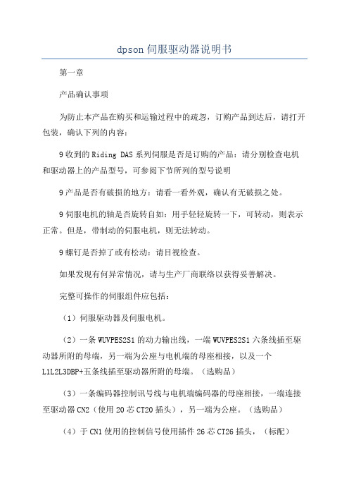
dpson伺服驱动器说明书 第一章 产品确认事项 为防止本产品在购买和运输过程中的疏忽,订购产品到达后,请打开包装,确认下列的内容:
9收到的Riding DAS系列伺服是否是订购的产品:请分别检查电机和驱动器上的产品型号,可参阅下节所列的型号说明
9产品是否有破损的地方:请看一看外观,确认有无破损之处。 9伺服电机的轴是否旋转自如:用手轻轻旋转一下,可转动,则表示正常。但是,带制动的伺服电机,则无法转动。
9螺钉是否掉了或有松动:请目视检查。 如果发现有何异常情况,请与生产厂商联络以获得妥善解决。 完整可操作的伺服组件应包括: (1)伺服驱动器及伺服电机。 (2)一条WUVPES2S1的动力输出线,一端WUVPES2S1六条线插至驱动器所附的母端,另一端为公座与电机端的母座相接,以及一个L1L2L3DBP+五条线插至驱动器所附的母端。(选购品)
(3)一条编码器控制讯号线与电机端编码器的母座相接,一端连接至驱动器CN2(使用20芯CT20插头),另一端为公座。(选购品)
(4)于CN1使用的控制信号使用插件26芯CT26插头,(标配) (5)于CN2使用的编码器信号使用插件20芯CT20插头(标配) (6)5PIN连接器插头(L1L2L3DBP+)(标配) (7)6PIN连接器插头(WUVPES2S1)(标配) 伺服放大器的接口示意图(1)5A伺服放大器构成1 (2)15A
构成 额定转速 适用电机输出 伺服放大器型号 0。1KWDAS120。8– VT0。2KWDAS121、5–VT0。4KWDAS122、7–VT0。6KWDAS123、5–VT单相200,230V
小惯量系列3000r、min 0。75KW DAS124、8–VT三相200,230V 中惯量系列 0。84KW DAS324、0–VT 2000r、min 1、05KWDAS325、0–VT 1、6KWDAS326。0–VT 2、1KWDAS3210。0–VT 第二章:配线及详细说明 2-1DAS系列通用驱动器接线图 2500r、min系列0。75KW,4KW 输入电源:单相200,230V或三相200,230V 动力配线:连接端子 -2-
- 1、下载文档前请自行甄别文档内容的完整性,平台不提供额外的编辑、内容补充、找答案等附加服务。
- 2、"仅部分预览"的文档,不可在线预览部分如存在完整性等问题,可反馈申请退款(可完整预览的文档不适用该条件!)。
- 3、如文档侵犯您的权益,请联系客服反馈,我们会尽快为您处理(人工客服工作时间:9:00-18:30)。
descriptionXenus Plus set new levels of performance, connectivity, and flexibility. CANopen communication provides a widely used cost-effective industrial bus. A wide range of absolute interfaces are built-in including EnDat, Hiperface, and BiSS.High resolution A/D converters ensure optimal current loop performance. Both isolated and high-speed non-isolated I/O are provided. For safety critical applications, redundant power stage enable inputs can be employed.Model Vac Ic Ip XPL-230-18100 - 240618XPL-230-36100 - 2401236XPL-230-40100 - 2402040Add -R for resolver feedback optioncontrol Modes• Indexer, Point-to-Point, PVT • Camming, Gearing• Position, Velocity, Torquecommand interface• CANopen• ASCII and discrete I/O • stepper commands• ±10V position/velocity/torque (2 inputs) • PWM velocity/torque command• Master encoder (Gearing/Camming)Communications• CAN • RS-232• RS-485 (Optional)Accessories• External regen resistors • External edge filterFeedback• Digital quad A/B encoder• EnDat, Hiperface, BiSS, SSI, & panasonic encoders• Aux. encoder / encoder out • Analog sin/cos encoder • Resolver option • Digital HallsSafe Torque Off (STO)• Two active inputs enable power stage • One output confirms power stage status I/O Digital• 15 inputs, 6 outputs I/O Analog• 2, 16 bit inputs • 1, 12 bit input • 1, 12 bit outputDimensions: in [mm]• 7.9 x 5.5 x 2.3 [202 x 139 x 52]GENERAL SPECIFICATIONSTest conditions: Wye connected load: 2 mH line-line. Ambient temperature = 25 °C. Power input = 230 Vac, 60 Hz, 1 ØModeL XPL-230-18 XPL-230-36 XPL-230-40OUTPUT CURRENTPeak Current 18 (12.7) 36 (25.5) 40 (28.3) Adc (Arms, sinusoidal)Peak time 1 1 1 sContinuous current (Note 1) 6 (4.24) 12 (8.5) 20 (14.1) Adc (Arms, sinusoidal)INPUT POWERMains voltage, phase, frequency 100~240 Vac, ±10%, 1Ø or 3Ø, 47~63 Hz Maximum Mains Current, 1Ø (Note 3) 10.1 20.0 20.0 ArmsMaximum Mains current, 3Ø (Note 3) 6.4 10.4 15.4 Arms+24 Vdc Control power +20 to +32 Vdc, 500 mA max Required for operationDIGITAL CONTROLDigital Control Loops Current, velocity, position. 100% digital loop controlSampling rate (time) Current loop: 16 kHz (62.5 µs), Velocity & position loops: 4 kHz (250 µs)Bus voltage compensation Changes in bus or mains voltage do not affect bandwidthMinimum load inductance 200 µH line-lineCOMMAND INPUTS (NOTE: DIGITAL INPUT FUNCTIONS ARE PROGRAMMABLE)Distributed Control ModesCANopen Position, Velocity, Torque, Homing, Profile, and Interpolated profile modesStand-alone modeAnalog torque, velocity, position reference ±10 Vdc, 16 bit resolution Dedicated differential analog inputInput impedance 74.8 kΩBetween Ref(+), Ref(-)Digital position reference Pulse/Direction, CW/CCW Stepper commands (2 MHz maximum rate)Quad A/B Encoder 2 M line/sec, 8 Mcount/sec (after quadrature) Digital torque & velocity reference PWM , Polarity PWM = 0% - 100%, Polarity = 1/0PWM 50% PWM = 50% ±50%, no polarity signal requiredPWM frequency range 1 kHz minimum, 100 kHz maximumPWM minimum pulse width 220 nsIndexing Up to 32 sequences can be launched from inputs or ASCII commands.Camming Up to 10 CAM tables can be stored in flash memoryASCII RS-232, 9600~115,200 Baud, 3-wire, RJ-11 connectorDIGITAL INPUTSNumber 15[IN1,2] Non-isolated Schmitt trigger, 1 µs RC filter, 24 Vdc max, Vt + = 2.5~3.5 Vdc, Vt- = 1.3~2.2 Vdc, VH+ = 0.7~1.5 Vdc10 kΩ programmable per input to pull-up to +5 Vdc or pull-down to ground[IN3~6] Non-isolated line receiver, 100 ns RC filter, +12 Vdc max, programmable as 4 single-ended, or 2 differentialSingle-ended: [IN3,4] or [IN5,6]: Vin-LO <= 2.3 Vdc, Vin-HI >= 2.7 Vdc, Vhysteresis = 400 mVdcDifferential: [IN3/4] or [IN5/6]: Vin-LO <= -200 mVdc, Vin-HI >= 200 mVdc, Vhysteresis = ±200 mVdc [IN7~14] Opto-isolated, ±15~30 Vdc compatible, bi-polar, 2 groups of 4 with common for each group[IN15] Encoder fault; same electrical specs as [IN1,2,15] except 10 kΩ fixed pull-up to +5 VdcANALOG INPUTSNumber 3[AIN1~2] Differential, ±10 Vdc, 5 kΩ input impedance, 16-bit resolution[AIN3] Single-ended, motor temperature sensor, 4.99 kΩ pulled-up to +5 Vdc, 12-bit resolutionDIGITAL OUTPUTSNumber 6[OUT1~2] Current-sinking MOSFET with 1 kΩ pullup to +5 Vdc through diode1 Adc max, +40 Vdc max; external flyback diode required if driving inductive loads[OUT3] High-speed CMOS buffer, ±32 mA[OUT4~5] Opto-isolated Darlingtons with 36V Zener flyback diodes, 20 mA max[OUT6] Motor brake control: opto-isolated, current-sinking with flyback diode to +24 Vdc, 1 Adc maxANALOG OUTPUTRange ±5 Vdc single-ended, 12-bit resolutionMULTI-MODE ENCODER PORTAs Input Secondary digital quadrature encoder (A, /A, B, /B, X, /X), 121 Ω terminating resistors18 M-counts/sec, post-quadrature (4.5 M-lines/sec)As Output Quadrature encoder emulation with programmable resolution to 4096 lines (65,536 counts) per revfrom analog sin/cos encoders or resolvers. Buffered signals from digital quad A/B/X primary encoderA, /A, B, /B, X, /X, from MAX3032 differential line driverRS-232 PORTSignals RxD, TxD, Gnd in 6-position, 4-contact RJ-11 style modular connectorMode Full-duplex, DTE serial communication port for drive setup and control, 9,600 to 115,200 baudProtocol Binary and ASCII formatsCAN PORTSignals CANH, CANL, Gnd in 8-position dual RJ-45 style modular connector, wired as per CAN Cia DR-303-1, V1.1Format CAN V2.0b physical layer for high-speed connections compliantData CANopen Device Profile DSP-402Address selection 16 position rotary switch on front panel with 3 additional address bits available asdigital inputs or programmable to flash memory (7-bit addressing, 127 nodes per CAN network)STATUS INDICATOR LEDSDrive Status Bicolor LED, drive status indicated by color, and blinking or non-blinking conditionCAN Status Bicolor LED, status of CAN bus indicated by color and blink codes to CAN Indicator Specification 303-3NOTES:1. Heatsinking and/or forced-air cooling is required for the continuous output power rating2. Brake[OUT6] is programmable as motor brake, or as general purpose digital output3. The actual mains current is dependent on the mains voltage, number of phases, and motor load and operating conditions. The Maximum Mains Currents shown aboveoccur when the drive is operating from the maximum input voltage and is producing the rated continuous output current at the maximum output voltage.5V OUTPUTTwo independent 5 Vdc @ 400 mA outputs: J8-20 and J10-6,17REGENERATIONOperation Internal solid-state switch drives external regen resistor (see Ordering Guide for types)Cut-In Voltage +HV > 390 Vdc Regen output is on, (optional external) regen resistor is dissipating energy Drop-Out Voltage +HV < 380 Vdc Regen output is off, (optional external) regen resistor not dissipating energy Tolerance ±2 Vdc For either Cut-In or Drop-Out voltage protections HV Overvoltage +HV > 400 Vdc Drive PWM outputs turn off until +HV is less than overvoltage HV Undervoltage +HV < 60 Vdc Drive PWM outputs turn off until +HV is greater than undervoltage Drive over temperature IGBT > 80 °C ±3 °C Drive PWM outputs turn off until IGBT temperature is below threshold Short circuitsOutput to output, output to ground, internal PWM bridge faults i 2T Current limiting Programmable: continuous current, peak current, peak timeMotor over temperature Programmable input to disable drive when voltage is above or below a set point 0~5 Vdc Feedback power loss Fault occurs if feedback is removed or +5 V is <85% of normalMECHANICAL & ENVIRONMENTAL Size 7.55 in (191,8 mm) X 5.57 in (141,5 mm) X 2.57 in (65,3 mm) Weight 3.0 lb (1.36 kg) for drive without heatsink3.1 lb (1.40 kg) for XPL-HS heatsink, 1.86 lb (0.84 kg) for XPL-HL heatsink Ambient temperature 0 to +45 °C operating, -40 to +85 °C storage Humidity 0% to 95%, non-condensing Contaminants Pollution degree 2Vibration 2 g peak, 10~500 Hz (sine), IEC60068-2-6 Shock 10 g , 10 ms, half-sine pulse, IEC60068-2-27 Environment IEC68-2: 1990CoolingHeat sink and/or forced air cooling required for continuous power outputAGENCy STANDARDS CONFORMANCEIn accordance with EC Directive 2004/108/EC (EMC Directive)EN 55011: 2007 CISPR 11:2003/A2:2006Industrial, Scientific, and Medical (ISM) Radio Frequency Equipment –Electromagnetic Disturbance Characteristics – Limits and Methods of Measurement Group 1, Class AEN 61000-6-1: 2007 Electromagnetic Compatibility (EMC) – Part 6-1: Generic Standards –Immunity for residential, Commercial and Light-industrial EnvironmentsIn accordance with EC Directive 2006/95/EC (Low Voltage Directive) IEC 61010-1:2001 Safety Requirements for Electrical Equipment for Measurement, Control and Laboratory Use Underwriters Laboratory Standards UL 61010-1, 2nd Ed.: 2004 Safety Requirements for Electrical Equipment for Measurement, Control and Laboratory Use UL File Number E24989425.40TYP2.3776.20diMensions Inches (mm)Chassis groundingtabFEEDBACk SPECIFICATIONSDIGITAL QUAD A/B ENCODERType Quadrature, differential line driver outputsSignals A, /A, B, /B, (X, /X, index signals optional)RS-422/RS-485 line receivers with fault detection for open/shorted inputs, or low signal amplitude Frequency 5 MHz line frequency, 20 MHz quadrature count frequencyANALOG ENCODERType Sin/cos/index, differential line driver outputs, 0.5 Vpeak-peak (1.0 Vpeak-peak differential)centered about 2.5 Vdc typical. Common-mode voltage 0.25 to 3.75 VdcSignals Sin(+), sin(-), cos(+), cos(-), index(+), index(-)Frequency 230kHz maximum line (cycle) frequencyInterpolation 10 bits/cycle (1024 counts/cycle)DIGITAL HALLSType Digital, single-ended, 120° electrical phase differenceSignals U, V, WInputs 10 kΩ pullups to +5 Vdc, 1 µs RC filter to Schmitt trigger invertersMULTI-MODE ENCODER PORTAs Input Secondary digital quadrature encoder (A, /A, B, /B, X, /X), 121 Ω terminating resistors18 M-counts/sec, post-quadrature (4.5 M-lines/sec)As Emulated Output Quadrature encoder emulation with programmable resolution to 4096 lines (65,536 counts) per revfrom analog sin/cos encoders or resolvers.A, /A, B, /B, X, /X, from MAX3032 differential line driverAs Buffered Output Digital encoder feedback signals from primary digital encoder are buffered by MAX3032 line driver RESOLVER (-R OPTION)Type Brushless, single-speed, 1:1 to 2:1 programmable transformation ratioResolution 14 bits (equivalent to a 4096 line quadrature encoder)Reference frequency 7.5 kHzReference voltage 2.8 Vrms, auto-adjustable by the drive to maximize feedbackReference maximum current 100 mAMaximum RPM 10,000+ENCODER POWER SUPPLIESNumber 2Ratings +5 Vdc @ 400 mA from J10-6 and J8-20Protection Current-limited to 750 mA @ 1 Vdc if overloadedEncoder power developed from +24 Vdc so position information is not lost when AC mains power is removedSAFE TORQUE OFF (STO)Inputs 2 two-terminal: [ENH+], [ENH-], [ENL+], [ENL-]Type Opto-isolators, 24V compatibleOutput 1 two-terminal: [LED+], [LED-]24V compatiblenote!help you get the best results when using Copley Controls products.6915D-Sub 9F3322CAN_L CAN_GNDCAN_HCAN_L RJ-45CAN_GND CAN_H71J7Pin 8CANOPEN CONNECTORSDual RJ-45 connectors that accept standard Ethernet cables are provided for CAN bus connectivity. Pins are wired-through so that drives can be daisy-chained and controlled with a single connection to the user’s CAN interface. A CAN terminator should be placed in the last drive in the chain. The XPL-Nk connector kit provides a D-Sub adapter that plugs into a CAN controller and has an RJ-45 socket that accepts the Ethernet cable.XPL-Nk CAN CONNECTOR kITThe kit contains the XPL-CV adapter that converts the CAN interface D-Sub 9M connector to an RJ-45 Ethernet cable socket, plus a 10 ft (3 m) cable and terminator . Both connector pin-outs conform to the CiA DR-303-1 specification.J7 CAN CONNECTIONSpin SIGNAL 2RxD 3,4Gnd 5TxdJ6: RS-232 PORTRJ-12 receptacle, 6 position, 4 contactSTAT LED (ON J6)A bi-color LED gives the state of the Xenus Plus drive. Colors do not alternate, and can be solid ON or blinking:Green/Solid = Drive Ok and enabled. Will run in response to reference inputs or EtherCAT commands. Green/Slow-Blinking = Drive Ok but NOT-enabled. Will run when enabled.Green/Fast-Blinking = Positive or Negative limit switch active. Drive will only move in direction not inhibited by limit switch. Red/Solid = Transient fault condition. Drive will resume operation when fault is removed. Red/Blinking = Latching fault. Operation will not resume until drive is Reset.Drive Fault conditions: • Over or under-voltage • Motor over-temperature • Encoder +5 Vdc fault • Drive over-temperature • Short-circuits from output to output • Short-circuits from output to ground • Internal short circuitsFaults are programmable to be either transient or latchingSTATnetCOMMUNICATIONSRS-232 MULTI-DROPThe RS-232 specification makes no allowance for more than two devices on a serial link. But, multiple Xenus drives can communicateover a single RS-232 port by daisy-chaining a master drive to other drives using CAN cables. In the CAN protocol, address 0 is reserved for the CAN master and thereafter all other nodes on a CAN network must have unique, non-zero addresses. When the Xenus CANaddress is set to 0, it acts as a CAN master , converting the RS-232 data into CAN messages and passing it along to the other driveswhich act as CAN nodes.CAN Addr 0CAN Master CAN Node CAN NodeCAN Addr 1CAN Addr nTxD RxD RJ-1153GndGndRxD TxD6915D-Sub 9FASCII COMMUNICATIONSThe Copley ASCII Interface is a set of ASCII format commands that can be used to operate and monitor Copley Controls Accelnet, Stepnet, and Xenus series amplifiers over an RS-232 serial connection. For instance, after basic amplifier configuration values have been programmed using CME 2, a control program can use the ASCII Interface to:• Enable the amplifier in Programmed Position mode.• Home the axis.• Issue a series of move commands while monitoring position, velocity, and other run-time variables.Additional information can be found in the ASCII Programmers Guide on the Copley website:/Motion/pdf/ASCII_ProgrammersGuide.pdfpin SIGNAL 2RxD 3,4Gnd 5TxdJ6: RS-232 PORTRJ-11 receptacle, 6 position, 4 contactRS-232 COMMUNICATIONSXPL is configured via a three-wire, full-duplex DTE RS-232 port that operates from 9600 to 115,200 Baud, 8 bits, no parity, and one stop bit. Signal format is full-duplex, 3-wire, DTE using RxD, TxD, and Gnd. Connections to the XPL RS-232 port are through J7, an RJ-11 connector . The XPL Serial Cable kit (SER-Ck) contains a modular cable, and an adapter that connects to a 9-pin, Sub-D serial port connector (COM1, COM2, etc.) on PC’s and compatibles.SER-Ck SERIAL CABLE kITThe SER-Ck provides connectivity between a D-Sub 9 male connector and the RJ-11 connector on the XPL. It includes an adapter that plugs into the COM1 (or other)port of a PC and uses common modular cable to connect to the XPL. The connections are shown in the diagram below.Don’t forget to order a Serial Cable kit SER-Ck when placing your order for an XPL!For Serial-multi-drop you’ll need an Serial Cable Kit SER-CK plus CANopen network cables to connect the drives as shown. The XPL-NC-01 and XPL-NC-10 are 1 ft (0.3m) and 10 ft (3m) cables that will do the job.These connections MUST be made to enable the Xenus.Xenus PlusSTO (Safe Torque Off)Override ConnectionsdescriptionThe XPL has a safety feature that is designed to provide the Safe Torque Off (STO) function as defined in IEC 61800-5-2. Two opto-couplers are provided which, when de-energized, prevent the upper and lower devices in the PWM outputs from being operated by the digital control core. Thisprovides a positive OFF capability that cannot be overridden by the control firmware, or associated hardware components. When the opto-couplers are activated (current is flowing in the input diodes), the control core will be able to control the on/off state of the PWM outputs.SAFE TORQUE OFF (STO)FUNCTIONAL DIAGRAMIn order for the PWM outputs of the Xenus Plus to be activated, current must be flowing through both opto-couplers that are connected to the ENH and ENL terminals of J5, and the drive must be in an ENABLED state. The LED outputs on J5 connect an opto-coupler to an external LED and will conduct current through the LED to light it whenever the PWM outputs can be activated, or the drive is in a diagnostic state. When the LED opto-coupler is OFF , the drive is in a Safe state and the PWM outputs cannot be activated to drive a motor .STO OVERRIDEThe diagram below shows connections that will energize both ENH and ENL opto-couplers.When this is done the STO feature is defeated and control of the output PWM stage is under control of the digital control core. If not using the STO feature, these connections must be made in order for the Xenus to be enabled.sto connectorFUNCTIONAL DIAGRAMpin SIGNAL pin SIGNAL 1Frame Gnd 6Enable LED(+)2Safe Enable HI(+)7Enable LED(-)3Safe Enable HI(-)824 Vdc Common 4Safe Enable LO(+)9+24 Vdc Input5Safe Enable LO(-)J5 SIGNALSJ51695SAFETYCOMMAND INPUTSDIGITAL POSITIONDigital position commands can be in either single-ended or differential format. Single-ended signals should be sourced from devices with active pull-up and pull-down to take advantage of the high-speed inputs. Differential inputs have 121 Ω line-terminators.DIGITAL TORQUE, VELOCITyDigital torque or velocity commands can be in either single-ended or differential format. Single-ended signals must be sourced from devices with active pull-up and pull-down to take advantage of the high-speed inputs.SINGLE-ENDED PWM & DIRECTIONSINGLE-ENDED 50% PWMDIFFERENTIAL 50% PWMDIFFERENTIAL PWM & DIRECTIONSINGLE-ENDED PULSE & DIRECTIONSINGLE-ENDED CU/CDCU (Count-Up)CD (Count-Down)QUAD A/B ENCODER SINGLE-ENDEDEncoder ph. BEncoder ph. ADIFFERENTIAL CU/CDDIFFERENTIAL PULSE & DIRECTIONQUAD A/B ENCODER DIFFERENTIALEncoder ph. AEncoder ph. BDuty = 0~100%Duty = 50% ±50%<no connection>This port consists of three differential input/output channels that take their functions from the Basic Setup of the drive.With quad A/B encoder feedback, the port works as an output, buffering the signals from the encoder . With resolver or sin/cos encoder versions, the feedback is converted to “emulated” quad A/B/X signals with programmable resolution. These signals can then be fed back to an external motion controller that closes the position or velocity loops. As an input, the port can take quad A/B signals to produce a dual-loop position control system or use the signals as master-encoder commands in camming mode. In addition, the port can takestepper command signals (CU/CD or Pulse/Direction) in differential format.Secondary Encoder Input Input/Output Select AS BUFFERED OUTPUTS FROM A DIGITAL QUADRATURE PRIMARy ENCODERWhen using a digital quadrature feedback encoder , the A/B/X signals drive the multi-mode port output buffers directly. This is useful in systems that use external controllers that also need the motor feedback encoder signals because these now come from J8, the Control connector . In addition to eliminating “y” cabling where the motor feedback cable has to split to connect to both controller and motor , the buffered outputs reduce loading on the feedback cable that could occur if the motor encoder had to drive two differential inputs in parallel, each with it’s own 121 ohm terminating resistor .Secondary Encoder InputInput/Output Selector resolverAS EMULATED QUAD A/B/X ENCODER OUTPUTS FROM AN ANALOG SIN/COS FEEDBACk ENCODERAnalog sin/cos signals are interpolated in the drive with programmable resolution. The incremental position data is then converted back into digital quadrature format which drives the multi-mode port output buffers. Some analog encoders also produce a digital index pulse which is connected directly to the port’s output buffer . The result is digital quadrature A/B/X signals thatcan be used as feedback to an external control system.Input/Output SelectAS A MASTER OR CAMMING ENCODER INPUT FROM A DIGITAL QUADRATURE ENCODERWhen operating in position mode the multi-mode port can accept digital command signals from external encoders. These can be used to drive cam tables, or as master-encoder signals when operating in a master/slave configuration.AS DIGITAL COMMAND INPUTS IN PULSE/DIRECTION,PULSE-UP/PULSE-DOWN, ORDIGITAL QUADRATURE ENCODER FORMATThe multi-mode port can also be used when digital command signals are in a differential format. These are the signals that typically go to single-ended inputs. But, at higher frequencies these are likely to be differential signals inwhich case the multi-mode port can be used.Input/Output SelectMULTI-MODE ENCODER PORTAS COMMAND INPUTSAS AN OUTPUT FOR FEEDBACk SIGNALS TO AN EXTERNAL CONTROLLERINPUTSDIGITAL INPUTS [IN3~6]These inputs have all the programmable functions of the GP inputs plus these additional functions on [IN8] & [IN9] which can be configured as single-ended or differential:• PWM 50%, PWM & Direction for Velocity or Current modes• Pulse/Direction, CU/CD, or A/B Quad encoder inputs for Position or Camming modesDIFFERENTIAL SINGLE-ENDED 12 Vdc max12 Vdc maxNON-ISOLATED DIGITAL INPUTSInputs [IN1~2] are 24V tolerantThese are high-speed types with pull-up resistors to +5 Vdc and 1 µs RC filters when driven by active sources. The active level is programmable on each input. Input [IN1] is dedicated to the drive enable function. The remaining inputs [IN2~IN14] have programmable functions.HS Inputs [IN1~2]24 Vdc maxPLC outputs are frequently current-sourcing from 24V for driving grounded loads. PC based digital controllers commonly use NPN or current-sinking outputs. Set the Xenus inputs to pull-down to ground for current-sourcing connections, and to pull-up to 5V for current-sinking connections.+J8 ControlANALOG INPUTSTwo differential analog inputs with ±10 Vdc range have programmable functions. As a reference input [AIN1] can take position/velocity/torque commands from a controller . A second input [AIN2] is programmable for other functions. The ratio of drive output current or velocity vs. reference input voltage is programmable.J8J924V GND24VOPTO-ISOLATED DIGITAL INPUTSThese inputs have all the programmable functions of the GP inputs plus opto-isolation. There are two groups of four inputs, each with its’ own common terminal. Grounding the common terminal configures the inputs to work with current-sourcing outputs from controllers like PLC’s. When the common terminal is connected to +24V , then the inputs will be activated by current-sinking devices such as NPN transistors or N-channel MOSFETs. The minimum ON threshold of the inputs is ±15 Vdc.J924V GND24V[IN11~14][IN7~10]±30 Vdc max±30 Vdc maxInputs [7~14] work with current-sourcing OR current-sinking connections. Connect the COMM to controller ground/common for current-sourcing connections and to 5~24V from the controller for current-sinking connections.J9DIGITAL OUTPUTS [OUT1], [OUT2]These are open-drain MOSFETs with 1 k Ω pull-up resistors in series with a diode to +5 Vdc. They can sink up to 1 Adc from external loads operating from power supplies to +30 Vdc. The output functions are programmable. The active state of the outputs is programmable to be on or off. When driving inductive loads such as a relay, an external fly-back diode is required.The internal diode in the output is for driving PLC inputs that are opto-isolated and connected to +24 Vdc. The diode prevents conductionfrom +24 Vdc through the 1 k Ω resistor to +5 Vdc in the drive. This could turn the PLC input on, giving a false indication of the drive output state.OUTPUTSANALOG OUTPUTThe analog output is programmable and has an output voltage range of ±5 Vdc. An op-amp buffers the output of a 12-bit D/A converter .HIGH SPEED OUTPUT [OUT3]5V CMOSOPTO-ISOLATED OUTPUTS [OUT4,5]30 Vdc maxZener clamping diodes across outputs allow driving of resistive-inductive (R-L) loads without external flyback diodes.J8BRAkE OUTPUT [OUT6]This output is an open-drain MOSFET with an internal flyback diode connected to the +24 Vdc input. It can sink up to 1A from a motor brake connected to the +24 Vdc supply. The operation of the brake is programmable with CME 2. It can also be programmed as a general-purpose digital output.+J4QUAD A/B ENCODER WITH FAULT PROTECTIONEncoders with differential line-driver outputs provide incremental position feedback via the A/B signals and the optional index signal (X) gives a once per revolution position mark. The MAX3097 receiver has differential inputs with fault protections for the following conditions:Short-circuits line-line: This produces a near-zero voltage between A & /A which is below the differential fault threshold.Open-circuit condition: The 121Ω terminator resistor will pull the inputs together if either side (or both) is open. This will produce the same fault condition as a short-circuit across the inputs.Low differential voltage detection: This is possible with very long cable runs and a fault will occur if the differential input voltage is < 200mV .±15kV ESD protection: The 3097E has protection against high-voltage discharges using the Human Body Model.Extended common-mode range: A fault occurs if the input common-mode voltage isoutside of the range of -10V to +13.2VANALOG SIN/COS INCREMENTAL ENCODERThe sin/cos/index inputs are differential with 121 Ω terminating resistors and accept 1 Vp-p signals in the format used by incremental encoders with analog outputs, or with ServoTube motors.EncoderRESOLVER (-R MODELS)Connections to the resolver should be made with shielded cable that uses three twisted-pairs. Once connected, resolver set up, motor phasing, and other commissioning adjustments are made with CME 2 software. There are no hardwareadjustments.Motor connectionsMotor connections are of three types: phase, feedback, and thermal sensor . The phase connections carry the drive output currents that drive the motor to produce motion. A thermal sensor that indicates motor overtemperature is used to shut down the drive to protect the motor . Feedback can be digital quad A/B encoder , analog sin/cos encoder , resolver or digital Halls, depending on the version of the drive.SSI ABSOLUTE ENCODERThe SSI (Synchronous Serial Interface) is an interface used to connect an absolute position encoder to a motion controller or control system. The XPL drive provides a train of clock signals in differential format to the encoder which initiates the transmission of the position data on the subsequent clock pulses. The polling of the encoder data occurs at the current loop frequency (16 kHz). The number of encoder data bits and counts per motor revolution are programmable. The hardware bus consists of two signals: SCLk and SDATA. Data is sent in 8 bit bytes, LSB first. The SCLk signal is only active during transfers. Data is clocked out on the falling edge and clock in on the rising edge of the Master .ENDAT ABSOLUTE ENCODERThe EnDat interface is a Heidenhain interface that is similar to SSI in the use of clock and data signals, but which also supports analog sin/cos channels from the same encoder . The number of position data bits is programmable as is the use of sin/cos channels. Use of sin/cos incremental signals is optionalin the EnDat specification.B i SS ABSOLUTE ENCODERBiSS is an - Open Source - digital interface for sensors and actuators. BiSS refers to principles of well known industrial standards for Serial Synchronous Interfaces like SSI, AS-Interface® and Interbus® with additional options.Serial Synchronous Data Communication Cyclic at high speed 2 unidirectional lines Clock and Data Line delay compensation for high speed data transfer Request for data generation at slaves Safety capable: CRC, Errors, Warnings Bus capability incl. actuators Bidirectional BiSS B-protocol: Mode choice at each cycle start BiSS C-protocol: Continuous modeNIkON-A ABSOLUTE ENCODERThe Nikon A interface is a serial, half-duplex type that iselectrically the same as RS-485BiSSNikon-AXenus。