伦茨9400中文使用手册.
RQ940系统用户手册
RQ940系统用户手册LT1112.1.2 系统前面介绍 (16)2.1.3 系统后面介绍 (17)2.1.4 电源模块后面介绍 (18)2.1.5 前面板LED 定义 (18)2.2 系统主要部件拆装 (19)2.2.1 硬盘支架的拆装 (20)2.2.2 硬盘的拆装 (21)2.2.3 电源的拆装 (21)2.2.4 上盖的拆装 (22)2.2.5 风扇模组的拆装 (23)12.2.7 中间支架拆装 (24)2.2.8 热插拔PCIE 卡拆装 (25)2.2.9 非热插拔PCIE 卡的拆装 (26)2.2.10 内存卡的拆装 (26)2.2.11 内存的拆装 (27)2.2.12................................................................................................................................................................................... CPU 散热器的拆装 (28)2.2.13................................................................................................................................................................................... CPU 的拆装 (29)2.2.14................................................................................................................................................................................... I/O 卡的拆装 (31)2.2.15................................................................................................................................................................................... B的拆装 (31)2.2.16................................................................................................................................................................................... supercap 的拆装 (32)2.2.17................................................................................................................................................................................... i bbu 的拆装 (33)2.2.18 导轨组件的拆装(上机柜) (35)第三章系统设置 (36)3.1 主板主要布局 (36)3.2 主板跳线设置及功能描速 (37)3.3主板BIOS 设置 (38)3.3.1 通电自检程序(POST) (38)3.3.2..................................................................................................................................................................................... B IOS 设置操作说明 (39)3.3.3..................................................................................................................................................................................... B IOS 设置项介绍 (39)3.3.4..................................................................................................................................................................................... Main 主菜单 (40)3.3.5..................................................................................................................................................................................... Advanced 主菜单 (41)3.3.6..................................................................................................................................................................................... I ntel RC Setup 主菜单 (60)23.3.7..................................................................................................................................................................................... Server Mgmt 主菜单 (88)3.3.8..................................................................................................................................................................................... BOOT 主菜单 (93)3.3.9..................................................................................................................................................................................... Security 主菜单 (96)3.3.10................................................................................................................................................................................... Save & EXIT 主菜单 (99)3.4 系统管理用户界面介绍 (100)第四章常用操作系统安装指南 (130)4.1 LSI 9270CV-8i 配置 (130)4.1.1Windows Server 2008 Datacenter Edition R2 with SP1 安装指南 (130)4.1.1.1 准备工作 (130)4.1.1.2 安装步骤 (130)4.1.1.3 芯片组驱动的安装 (131)4.1.1.4 网卡驱动的安装 (131)4.1.1.5 板载显卡驱动的安装 (132)4.1.2Windows Server 2012 Datacenter 安装指南 (132)4.1.2.1 准备工作 (132)4.1.2.2 安装步骤 (132)4.1.2.3 芯片组驱动的安装 (133)4.1.2.4 板载显卡驱动的安装 (133)4.1.2.5 网卡驱动程序安装 (133)4.1.3Windows Server Datacenter 2012R2 安装指南 (134)4.1.3.1 准备工作 (134)4.1.3.2 安装步骤 (134)4.1.3.3 芯片组驱动的安装 (134)4.1.3.4 板载显卡驱动的安装 (135)4.1.3.5 网卡驱动程序安装 (135)34.1.4Microsoft Hyper V 2012 安装指南 (135)4.1.4.1 准备工作 (135)4.1.4.2 安装步骤 (135)4.1.4.3 芯片组驱动的安装 (136)4.1.4.4 板载显卡驱动的安装 (136)4.1.4.5 网卡驱动的安装 (136)4.1.5RedHat Enterprise Linux AS 6.5 x64 安装指南 (137)4.1.5.1 安装步骤 (137)44.1.5.2 网卡驱动的安装及配置 (138)4.1.5.3 板载显卡驱动的安装 (138)4.1.6Suse Linux Enterprise Server 11 SP3 x64 安装指南 (139)4.1.6.1 安装步骤 (139)4.1.6.3 网卡驱动程序安装及配置 (140)4.1.6.4 板载显卡驱动的安装 (140)4.1.7VMware 安装指南 (140)4.1.7.1 安装步骤 (140)4.1.8Citrix XenServer Enterprise v6.2 安装指南 (141)4.1.8.1 安装步骤 (141)4.1.9Oracle Solaris 11 安装指南 (142)4.1.9.1 安装步骤 (142)第五章常见问题解答 (143)5.1 系统首次启动不正常 (143)5.2 应用软件运行不正常 (143)5.3 系统运行中的故障 (144)5.4 其他故障及解决方法 (144)5.4.1 显示器无法正常显示 (144)5.4.2 清除系统配置 (144)5.4.3 更换主板电池 (145)5.4.4 存储部件容量说明 (145)附录一服务器相关知识词汇表 (146)5声明感谢您选择联想产品。
伦茨 SMD系列变频器 说明书

17
c[mm]
83 92
m[kg]
0.5 0.6
93
85
146
128
17
141
1.2
114
105
146
128
17
140
1.4
114
105
146
128
17
171
1.9
114
105
146
100
17
171
1.7
型号
a[mm] a1[mm] b[mm] b1[mm] b2[mm] c[mm]
371L4TXA
[kW] 0.37 0.75 1.1 1.5 2.2 3.0 4.0 5.5 7.5 11 15
ESMD371L4TXA 0.37 ESMD751L4TXA 0.75 ESMD112L4TXA 1.1 ESMD152L4TXA 1.5 ESMD222L4TXA 2.2 ESMD302L4TXA 3.0 ESMD402L4TXA 4.0 ESMD552L4TXA 5.5 ESMD752L4TXA 7.5 ESMD113L4TXA 11 ESMD153L4TXA 15 ESMD183L4TXA 18.5 ESMD223L4TXA 22
52 45 46 40 42 37 69 60 64 55
①额定电压下 , 斩波频率为 4,6,8kHz 时 ②额定电压下 , 斩波频率为 10kHz 时 ③最大输出电流随 C90 的设定(选择输入电压)而改变
5
安装
4 安装
4.1 机械安装 4.1.1 1AC 控制器外形尺寸
> 50
b2 b1 b
电压,频率
1/N/PE 230/240V 2/PE 230/240V (180V-0%...264V+0%)
伦茨SMV变频器操作手册
伦茨SMV变频器操作手册伦茨SMV变频器操作手册目录1.引言1.1 简介1.2 目的1.3 目标读者2.变频器基本知识2.1 变频器概述2.2 变频器工作原理2.3 变频器的优势3.变频器安装步骤3.1 环境要求3.2 电源接线3.3 控制信号接线3.4 电机接线4.变频器参数配置4.1 参数总览4.2 基本参数设置4.3 输出频率配置4.4 过载保护参数设置 4.5 风扇控制参数设置4.6 控制方式选择5.变频器操作步骤5.1 变频器开机与关机 5.2 运行状态监测5.3 参数调整与保存5.4 故障诊断与处理6.变频器维护与保养6.1 日常维护事项6.2 清洁与防尘措施6.3 润滑与冷却管理7.附录7.1 常见问题解答7.2 故障代码与解决方法7.3 附件列表附录1.附件列表:- 1.SMV变频器安装手册.pdf- 2.SMV变频器参数配置表.xlsx- 3.SMV变频器维护与保养指南.doc2.法律名词及注释:- 变频器:全称为变频电力调速器,是一种能够改变电机转速的设备,在工业领域广泛应用。
- 频率:指单位时间内发生的事件次数,用赫兹(Hz)表示。
- 电源接线:将变频器与电源连接的一组电线,通常包括相线、零线和接地线。
- 控制信号接线:将变频器与外部控制设备连接的电线,用于实现运行控制和参数调整。
- 环境要求:指安装变频器的环境要符合一定的条件,如通风良好、温度适宜等。
- 过载保护:一种保护措施,当电机负载超过设定值时,变频器自动停止工作以避免损坏。
- 风扇控制:指控制变频器内部风扇运行的参数配置和调整。
- 控制方式:指变频器的运行控制方式,如键盘本地控制、远程控制等。
飞利浦 RFX9400 说明书

RFX9400 ZH 用户指南EN Starter’s Guide独立模式网络模式独立模式该模式又称为“对等模式”:不需要使用路由器。
独立模式的优点:• 容易安装和配置延伸器。
• 延伸器独立于其它网络和网络设置工作。
请参阅第 4 页上的“独立连接”一章,用独立模式配置延伸器。
注意 如果想要将多媒体服务器(如Escient Fireball)与一个或多个延伸器结合使用, 则必须使用网络模式配置延伸器。
网络模式这也称为“基础设施模式”:即在具有路由器的网络中使用延伸器。
网络模式的优点:• 网络允许使用转发器,转发器可扩大 Pronto 系统的信号范围。
• 在使用专用 Pronto 网络时,延伸器可独立于其它网络中的设置工作。
• 可以为网络模式下的延伸器指定一个固定 IP 地址,以提高可靠性。
• 还可以对网络连接加密。
请参阅第 4 页上的“网络连接”一章,在网络模式下配置延伸器。
注意 已经在独立模式下配置的延伸器总是可以重新配置为在网络模式下使用, 反之亦然。
可以在同一个 Pronto网络中使用16 个不同的延伸器。
天线IP 地址4 个 IR 输出延伸器 ID 开关以太网输入 (RJ45)以太网交叉线缆指示灯忙指示灯以太网指示灯注意 • 如果已经有一个延伸器将路由器无线接入点以太网直线缆延伸器无线接入点控制板控制板在设置无线网络连接时,确保控制板总是至少显示了一格 WiFi 连接信号。
如果情况不是如此,您可能需要在网络中增加无线接入点。
配置线缆Network2延伸器将重新启动。
启动之后:开关..设置为PC 上打开Extender Discovery”此时将打开延伸器发现工具,上面显示了在 Pronto 网络中检测到的所有延伸器选择您要配置的延伸器,然后单击“Configure ”(配置)按钮。
输出将它连接到 以太网直线缆路由器将发射器连接到 A/V 接收器。
输出的功率大小打开浏览器。
在.PC.上打开.ProntoEdit ProfessionalStand-alone Mode Network ModeE N G L I S Stand-alone ModeThis is the so-called ‘Ad-Hoc Mode’: a router is not required.Stand-alone Advantages:• The Extender is easily configured and installed.• It operates independently from other networks and network settings.Refer to the chapter ‘Stand-alone Connection’ on page 4 to configure the Extender in Stand-alone Mode.NoteIf you want to use a Multimedia server, like the Escient Fireball, in combination with one or more Extenders, the Extenders have to be configured in Network Mode.Network ModeThis is the so-called ‘Infrastructure Mode’: the Extender is used in a network with a router.Network Advantages:• A network allows the use of repeaters, which enlarges the range of the Pronto System.• When using a dedicated Pronto Network, the Extender can operate independently from settings in other networks.• The Extender in Network Mode can be given a fixed IP address, which increases reliability.• The network connection can be encrypted.Refer to the chapter ‘Network Connection’ on page 4 to configure the Extender in Network Mode.NoteAn Extender that has been configured in Stand-alone Mode can always be reconfigured for use in Network Mode and vice versa.You can use up to 16 different Extenders in the same Pronto Network.Pronto Wireless ExtenderAntennaIP address4 IR outputsExtender ID switchEthernet input (RJ45)Power Adapter Crossed Ethernet cableWiFi LED Ethernet LEDBusy LEDNote• If there is already an Extender with ID 0, set the Extender ID switch to an ID that is not There are two ways to use the Extender in a network:ExtenderRouterWireless Access PointStraight Ethernet CableExtenderWireless Access PointControl PanelControl PanelWhen you set up a Wireless Network connection, make sure the Control Panel always shows minimal one bar of WiFi connectivity. If this is not the case, you may need additional Wireless Access points in your network.cableStand-alone/Network NetworkConfiguration switch 2Note • If there is already an Extender with ID 0, set the Extender ID switch to an ID that is not The Extender will restart. After startup,Configuration switch ..to.3.ProntoEdit Professional Extenderwith a list of all the detected Extenders in the Pronto Network.Select.the.Extender.that.you.want.to.configure.and.click.on.the.Configure .button.The Configuration Tool opens in the browser.For the Extender to transmit an IR signal, you need to connect it to the A/V component via the IR Output on the back of the Extender. In contrast to previous Philips Extenders, the RFX9400 has no IR To connect the Extender to A/V equipment, use one of the following cables enclosed with the StraightEthernet cableRouterconnector of the Dual output of the Extender.Attach the emitter to the infrared receiver of the A/V component.Adjusting the Power Level of the IR OutputsAt the back of the Extender, there are 4 dipswitches, one for each IR output. Use these dipswitchesOpen.the.browser.Open.the.ProntoEdit Professional。
CN_3_lenze9400了解和固件

5
9400 Servo Drives
Software in the 9400 Servo Drive
ID tags
Contents, partitions, read through display codes 内容,分类,通过显示代码读取信息
Power section: C00203/7…8 Control card: C00204/7…8 Assembly: C00206/7…8 order-related final installation
– all extension modules 所有扩展模块 – all memory modules 所有存储模块 – SM100, SM30X safety modules 安全模块 What„s in it? 里面有什么内容? – hardware identification 硬件ID (type code, serial numbers, ...) (型号,序列号,...) – calibration data (DC-bus voltage, ...) 标准数据 – order-related final installation订单相关的最终安装信息 – service register (power-on time meter, ...) 服务寄存器 – etc.
LS_MotorInterface
LS_Feedback
Communication data,application, parameters (safe against mains failure), etc. 数据交换
Motor parameters,encoder information, etc.电机参数
服务寄存器 Firmware
伦茨变频器9400选型样本介绍

L-force样本自动化系统驱动系统解决方案控制装置变频器电机减速机工程设计工具变频器:伺服9400HighLineL-force样本的内容Lenze,让许多事物变得简单。
关于Lenze我们的原则:用最合适的产品应对实际应用L-force产品系列1.1基于控制器的自动化自动化系统1.2基于驱动器的自动化2.1HighLine任务驱动系统解决方案2.2StateLine任务2.3BaseLine任务3.1控制器3200C柜式控制器控制装置3.2控制器c3003.3控制器p500面板控制器3.4控制器p3003.5I/O1000'3.6监控面板4.1变频器8400protec分布式变频器4.2变频器8400motec4.4柜式伺服9400HighLine4.5伺服8400TopLine4.6伺服驱动器i7004.7变频器8400HighLine4.8变频器8400StateLine4.10变频器8400BaseLine5.1同步伺服电机MCS伺服电机电机5.2MD☐KS同步伺服电机5.3异步伺服电机MQA5.4异步伺服电机MCA5.5三相交流电机MF三相交流电机5.6三相交流电机MH5.7三相交流电机MD5.8Lenze Smart电机m3005.9基础型MD/MH三相交流电机6.1g700-P行星轮减速机轴向减速机减速机6.2MPR/MPG行星轮减速机6.3g500-H斜齿轮减速机6.4GST斜齿轮减速机6.5g500-S小侧隙斜齿轮减速机6.6GFL小侧隙斜齿轮减速机6.7g500-B伞齿轮减速机直角减速机6.8GKR伞齿轮减速机6.9GKS螺旋伞齿轮减速机6.10GSS圆柱斜齿轮蜗轮蜗杆减速机6.11分配如上电机数据7.1Navigator工程设计工具7.2Drive Solution Designer7.3Drive Solution Catalogue7.4Engineer7.5PLC Designer7.6VisiWinNET®7.7EASY Starter精选组合附加组合Lenze,让许多事物变得简单。
TNW-9400多制式报警主机系统使用说明书

TNW-9400系统安装手册说明TNW-9400报警系统是具有很强的实用性被广泛地应用在别墅小区及周界报警系统、以及办公大楼等各类大型安保系统可实现计算机软件管理、云服务报警系统相连、并方便地与其它系统集成。
TNW-9400主要功能及性能指标一. 主要功能●最多可以接1024个防区,通过外扩RS485扩展板或IP扩展模块可以外接最多128个防区扩展模块或主机,最多可以支持1024个扩展防区。
●可最多接入8个键盘,独立操作,LCD显示。
各键盘分别对自己的所管辖的所有防区独立同时进行布防、撤防等操作。
通过主键盘可以编程,任意键盘可编程跟随所有报警并显示报警信息。
●主机本身最多支持8个有线防区。
●主机可通过RS485扩展板连接IH-LC08P-16(16路无线汇聚器)和IH-LCO8P-8(8路无线汇聚器)组成大型免信号线的总线制报警系统。
●可外扩WiFi/IP模块、GPRS模块,通过RS232或IP实现与中心软件计算机连接。
●通过WiFi/IP模块、GPRS模块实现和云服务报警系统连接。
●外扩电话模块支持3组中心电话号码报警、8组用户号码报警、1组布防号码上报、1组撤防号码上报。
●防区名称汉字任意更改,电脑配置,每个防区最多支持7个汉字。
●挂在RS485扩展通讯总线上的设备都可以带有1-16个输出,其防区扩展模块最多带有1个输出,联动输出设备最多可带16个输出。
每个防区可联动最多8个输出。
联动包括:防区报警联动、防区布撤防联动、防区异常联动。
可以达到电子地图、DVR报警输入、就地报警等功能。
●本机支持17组密码。
包括:1组安装密码、16组用户密码。
●通过键盘密码、遥控器、中心软件、手机APP软件、微信及操作键盘进行布撤防。
●分别可以存储1000条的报警和操作纪录,掉电保存。
●有20秒的电话报警语音,可以自己选择语音文件写入。
●通过电脑进行编程和配置。
可远程配置好,文件发送,就地写入主机,让编程和服务更为简单、有效。
T9400S-软件说明书
☆
4:辅助频率源 Y 与主辅运算结果切换
十位:频率源主辅运算关系
0:主+辅
1:主-辅
2:二者最大值
3:二者最小值
P0.08
预置频率
0.00Hz~最大频率(P0.10)
50.00Hz ☆
P0.09
运行方向
0:方向一致 1:方向相反
0
☆
P0.10
最大频率
50.00Hz~600.00Hz
50.00Hz ★
P4.34 AI 低于最小输入设定选择
P4.35 P4.36 P4.37
FWD 延迟时间 REV 延迟时间 S1 延迟时间
P4.38
S 端子有效模式选择 1
P4.39 S 端子有效模式选择 2
0:两线式 1
1:两线式 2
0
2:三线式 1
3:三线式 2
0.001Hz/s~65.535Hz/s
1.00Hz/s
T9400S-供水软件说明书-YL
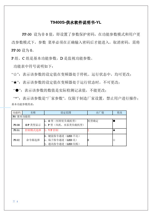
PP-00 设为非 0 值,即设置了参数保护密码,在功能参数模式和用户更 改参数模式下,参数 菜单必须在正确输入密码后才能进入,取消密码,需将 PP.00 设为 0。 P 组、C 组是基本功能参数,D 是监视功能参数。 功能表中符号说明如下: “☆”:表示该参数的设定值在变频器处于停机、运行状态中,均可更改; “★”:表示该参数的设定值在变频器处于运行状态时,不可更改; “●”:表示该参数的数值是实际检测记录值,不能更改; “*”:表示该参数是“厂家参数”,仅限于制造厂家设置,禁止用户进行操作;
P4.11 端子命令方式
P4.12 P4.13 P4.14 P4.15 P4.16 P4.17 P4.18 P4.19 P4.20 P4.21 P4.22
- 1、下载文档前请自行甄别文档内容的完整性,平台不提供额外的编辑、内容补充、找答案等附加服务。
- 2、"仅部分预览"的文档,不可在线预览部分如存在完整性等问题,可反馈申请退款(可完整预览的文档不适用该条件!)。
- 3、如文档侵犯您的权益,请联系客服反馈,我们会尽快为您处理(人工客服工作时间:9:00-18:30)。
Diagnostic & parameter setting only
ready
Next Back
仅用于诊断和参数设定
Application is stored in the memory module
应用存储在存储模块中
6
9400 Servo Drives
Target First without engineer
Engineer with single drive,
basics of TA Structured project, further TA FB editor Multi axis applications Online alternatives
RFR Controller enable (Reglerfreigabe)控制器使能 DI1 Deactivation of quick stop 快停取消 DI2 Start 启动 AI1[%] Speed setpoint 速度设定
3. Switch off the 400 V supply voltage 切断400V电源
诊断接口
Resolver input
旋转变压器接口
Multi encoder input
编码器接口
Module receptacle for memory module
存储模块插槽
Module receptacle for safety technology
安全模块插槽
HighLine StateLine: 1 个扩展插槽
Start assistant 启动助手
Next Back
9
9400 Servo Drives
Target First without engineer
Engineer with single drive,
basics of TA Structured project, further TA FB editor Multi axis applications Online alternatives
Engineer with single drive, basics of TA Structured project, further TA FB editor Multi axis applications Online alternatives
Interfaces at the power module
Active application: “Actuator – speed“ (激活应用 Actuator – speed)
9400 Servo Drives
Target
First without engineer
Engineer with single drive, basics of TA Structured project, further TA FB editor Multi axis applications Online alternatives
9400 Servo Drives
Target
First without engineer
Engineer with single drive, basics of TA Structured project, further TA FB editor Multi axis applications Online alternatives
9400 Servo Drives
Target
First without engineer
Engineer with single drive, basics of TA Structured project, further TA FB editor Multi axis applications Online alternatives
Next Back
2
Introduction to L-force 9400 and engineer L-force 9400 和 engineer 的介绍
9400 servo drive set-up with interfaces 9400伺服的接口设置
Parameter setting with Engineer and keypad 通过Engineer 和 操作面板进行参数设定
9400 Servo Drives
Target
First without engineer Engineer with single drive, basics of TA Structured project, further TA FB editor Multi axis applications Online alternatives
Target
First without engineer
Engineer with single drive, basics of TA Structured project, further TA FB editor Multi axis applications Online alternatives
Analog / digital IOs
模拟/数字 I/O
CAN on board
内置CAN
24 V supply and state bus
24V和状态总线
2 module receptacles for extensions
2个扩展模块插槽
Next Back
4
LEDs
指示灯
Diagnostic interface
= Controller inhibited 控制器禁止
= Controller enabled 控制器使能
24 V
CAN ERROR
CAN 错误
= Bus warning 总线报警
= Bus off 总线关闭
DRIVE ERROR
驱动器错误 OFF = OK
= Error status 错误状态
= System error 系统错误
Technology Applications (TA) 技术应用
Diagnostics and configuration of the application with the function block editor 使用功能块编辑器的应用配置和诊断
Multi axis application with horizontal CAN communication 使用CAN总线通讯的多轴应用
Next Back
8
Exercise 1: Detect the drive status
by means of LEDs and keypad 通过指示灯和面板检测驱动器状态
1. Switch on the supply voltages (24 V and 400 V)
电源上电
2. Make the left drive rotate:运转左侧驱动器
User interface 用户界面
Menu bar
菜单栏
Tool bar
工具栏
View bar
浏览栏
Project tree
工程树
Work space
工作区
ready
Next Back
10
Messages and monitor panel
信息和监视盘
9400 Servo Drives
Welcome!
Practical introduction: 实用简介
L-force 9400 Servo Drives L-force | Engineer
19 January 2007
Trainer: Torsten Heß, Markus Toeberg, Markus Warnecke, Stefan Witte
2x Motor MCS06C41 with resolver and tooth wheel(2个 伺服电机带旋变和齿型轮)
– left Z = 72 and 32 (左 Z=72,32) – right Z = 60 and 20 (右Z=60,20)
Next Back
7
Belt 皮带 – left L = 600 mm; Z = 120 (左L=600mm;Z=120) – right L = 535 mm; Z = 107 (右L=535mm;Z=107)
Keypad
面板
4 direction keys for navigation
4个方向键用于导航
2 context-sensitive function keys
2个功能键
Run and stop keys (configurable) 运行和停止键(可配置)
Status field
4. Find out the drive status by means of the LEDs and the keypad 通过指示灯和面板观察状态
5. Make the logbook being displayed at the keypad
对面板显示进行记录
9400 Servo Drives
ready
Next Back
5
LEDs
指示灯
CAN RUN
CAN 运行
OFF
= CAN inactive CAN没激活
= Pre-operational 预操作
= Operational 操作
DRIVE READY
驱动器投入
OFF
= Pulse inhibit due to an error 由于错误而禁止