APx音频测试仪操作说明书
APX500音频分析仪使用简易图解
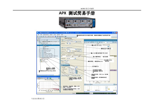
APX 测试简易手册专业知识整理分享信号路径的设置蓝牙播放器测试1.在信号源路径中选择bluetooth.2.点击settings 进行配对连接。
3.选择A2DP Source HSP4.点击Scan for devices 搜索被测产品5.点击pair 进行配对6.连接A2DP 协议7.开始测试相关测试项目专业知识整理分享蓝牙主机(Audio Gateway)的测试1.Input Configuraton 路径设置为bluetooth2.点击settings 进行配对连接。
3.选择A2DP link ( Hand-free 或者headset)4.点击Scan for devices 搜索被测产品5.点击pair 进行配对6.连接A2DP 协议7.开始测试相关测试项目专业知识整理分享功放测试1.根据实际接线,设置信号源的输出信号方式2.根据实际接线,设置分析仪的输入信号方式专业知识整理分享DVD、CD的测试1.信号源设为none2.分析仪接口设置与实际接线方式一致。
专业知识整理分享选择测试项目根据测试需求增加项目专业知识整理分享专业知识整理分享专业知识整理分享电平测试1.设置信号源输出波形2.设置信号源大小3.设置信号源频率4.打开信号源开关5.读取测量值专业知识整理分享失真测试1设置信号源输出波形,2设置信号源大小3设置信号源频率4打开信号源开关专业知识整理分享6读取测量值信噪比测试1设置信号源输出波形2设置信号源大小3设置信号源频率4打开信号源开关专业知识整理分享6读取测量值频率扫描测试1.设置信号源波形2.设置信号源大小3.设置信号源开始频率,结束频率,扫描点数4.设置滤波器专业知识整理分享5.点击Start 开始测试。
总谐波失真加噪声频率扫描测试1设置信号源波形2设置信号源大小3设置信号源开始频率,结束频率,扫描点数专业知识整理分享4设置滤波器5 点击Start 开始测试生成测试报告专业知识整理分享专业知识整理分享。
Sophos APX 320X 操作指南说明书
Operating Instructions APX 320XForewardWe are pleased to welcome you as a new Sophos APX Series customer.Sophos APX Series access points are high performance wireless products using the latest 802.11ac Wave 2 technology for a best-in-class user experience. The APX Series models can be easily managed in Sophos Central, our cloud-based security management platform. All you need to do is set up a Sophos Central account and plug in the device anywhere in your network. The access point will find the cloud-based controller automatically and become operable within seconds.These operating instructions will help you set up your Sophos Central account, install and configure your Sophos APX Series access point and also provide detailed technical specifications. In addition, please also see the following documents that contain useful information on safety, regulatory compliance, and configuration options:ÌSophos APX Series Safety Instructions and Regulatory InformationÌSophos APX 320X Quick Start GuideThe instructions must be read carefully prior to using the device and should be kept in a safe place. You can download all user manuals and additional documentation from the Sophos Knowledgebase under /en-us/support/knowledgebase.aspx or from /get-started-ap.Security symbolsThe following symbol and its meaning appears in the Quick Start Guide, Safety Instructions and in these Operating Instructions.Caution and Important Note. If these notes are not correctly observed:ÌThis is dangerous to life and the environmentÌThe access point may be damagedÌThe functions of the access point will be no longer guaranteedÌSophos shall not be liable for damages arising from afailure to comply with the Safety InstructionsDesigned useThe access point must be installed pursuant to the current installation notes. Otherwise failure-free and safe operation cannot be guaranteed. The EU declaration of conformity is available upon request from the following address:Sophos Technology GmbHGustav-Stresemann-Ring 165189 WiesbadenGermanyOperating elements and connections N type connector for 2.4/5 GHz antenna (Radio 1)N type connector for 2.4/5 GHz antenna(Radio 0)N type connector for 2.4/5 GHz antenna (Radio 1)N type connector for 2.4/5 GHz antenna(Radio 0)Forge posts for mounting plate connection Gore vent LED RJ45 connector/Reset button Grounding wireconnectorComponent descriptionsLEDs* Your AP should recover from this state after a maximum of 5 minutes.Connection and configurationYour access point can be managed by a wireless controller located in Sophos Central. The initial connection of your access point to your network and the wireless controller is described in the APX Quick Start Guide which was shipped with your device or is available under /get-started-ap.For the access point to communicate with Sophos Central servers the following ports will need to be open on your firewall:Ì443 (HTTPS)Ì80 (HTTP)Ì123 (NTP)After successful connection you can start your initial configuration.Setting up your access point in Sophos CentralYou will need a Sophos Central account to manage your access points from Sophos Central. Please go to https:// to sign in under your account or create a new account.After signing in select Wireless from the popup screen or click on Wireless in the left navigation to get started.Follow the Onboarding Wizard to register your access point.For more information, please see the Sophos Central Admin Help.Setting up your access point in XG FirewallPlease note: APX 320X is not supported on XG or XGS Firewalls.Reboot and resetYour access point can be rebooted with the installed configuration or reset to the factory default configuration depending on how long you press and hold the reset button. Reboot with current image and configuration1. Press reset button.2. Release reset button.3. AP reboots (LED will go off, then will turn to solid green).Reboot with current image and clear configuration1. Press and hold reset button.2. AP reboots (LED will go off and then switch to green briefly).3. LED will turn solid red for 5 sec. You can still cancel the configuration clearanceprocess by releasing the reset button before the LED starts blinking.4. LED will blink red (configuration will be cleared).5. Release reset button.6. AP reboots with factory default settings.Technical specifications* Not available in the countries listed here: https:///support/s/article/KB-000039850 ** For the countries listed here: https:///support/s/article/KB-000039850Radiation patterns2.4 GHz BandH-plane V-plane—2400 (MHz) —2450 (MHz) —2500 (MHz)5 GHz BandH-plane V-plane—4900 (MHz) —5150 (MHz) —5350 (MHz)—5475 (MHz)—5725 (MHz)—5875 (MHz)Optional Sector / Directional AntennasTechnical specifications120° Sector AntennaFrequency range2400~2500 MHz5150~5850 MHzPort V-pol. / H-pol.V-pol. / H-pol.Antenna Gain10.6~10.8 dBi) / 10.0~11.4 dBi 12.5~13.1 dBi / 11.6~12.9 dBi HPBW / Horizontal76~77 deg / 63~66 deg40~61 deg / 52~76 deg HPBW / Vertical24~25 deg / 26~28 deg11~13 deg / 11~13 deg Isolation20 dBImpedance50 OhmsConnector N JackDimensions320 x 200 x 20.5 mm (12.6 x 7.87 x 0.81 inches)(Height x Width x Depth)30° Directional AntennaFrequency range2400~2500 MHz5150~5850 MHzPort V-pol. / H-pol.V-pol. / H-pol.Antenna Gain11.6~11.8 dBi) / 11.6~12.0 dBi 10.6~11.0 dBi / 10.4~11.5 dBi HPBW / Horizontal36~37 deg / 35~36 deg33~35 deg / 26~36 deg HPBW / Vertical34~35 deg / 36~38 deg32~39 deg / 30~41 deg Isolation20 dBImpedance50 OhmsConnector N JackDimensions320 x 200 x 20.5 mm (12.6 x 7.87 x 0.81 inches)(Height x Width x Depth)Radiation patterns Sector Antenna – Horizontal Polarization 2.4 GHz BandH-plane V-plane—2400 (MHz) —2450 (MHz) —2500 (MHz)5 GHz BandH-plane V-plane—4900 (MHz) —5150 (MHz) —5350 (MHz)—5475 (MHz)—5725 (MHz)—5875 (MHz)Radiation patterns Sector Antenna – Vertical Polarization 2.4 GHz BandH-plane V-plane—2400 (MHz) —2450 (MHz) —2500 (MHz)5 GHz BandH-plane V-plane—4900 (MHz) —5150 (MHz) —5350 (MHz)—5475 (MHz)—5725 (MHz)—5875 (MHz)H-plane V-plane—2400 (MHz) —2450 (MHz) —2500 (MHz)5 GHz BandH-plane V-plane—4900 (MHz) —5150 (MHz) —5350 (MHz)—5475 (MHz)—5725 (MHz)—5875 (MHz)H-plane V-plane—2400 (MHz) —2450 (MHz) —2500 (MHz)5 GHz BandH-plane V-plane—4900 (MHz) —5150 (MHz) —5350 (MHz)—5475 (MHz)—5725 (MHz)—5875 (MHz)Mounting instructionsThere are various mounting options available allowing you to hang your access point on the wall or mount it on a pole. Both options require the use of the mounting bracket which is shipped with your access point. The following sections provide detailed instructions on each of these options.Mounting bracketMounting holesVertical orientation mounting clamp slots Horizontal orientation mounting clamp slotsMountingattachment slotsMount plateattachment screwWall mount1. Use the mounting bracket to mark the screw mounting positions on the wall.2. Attach the access point to the bracket by hanging the 4 forge postsinto the attachment slots of the bracket and pressing it down.3. Tighten the attachment screw to fix the access point to the bracket.1.3.Tighten the attachment screwPole mount1. Attach the two metal clamps to the back of the mounting bracket using thevertical or horizontal mounting slots (according to the desired orientation).2. Hold the bracket against the pole and tighten the metal clamps.3. Attach the access point to the bracket by hanging the 4 forge postsinto the attachment slots of the bracket and pressing it down.4. Tighten the attachment screw to fix the access point to the bracket1. 2.3. 4.Sector / Directional Antenna Mounting Instructions1. Attach the articulating mount to the back of the Sector /Directional antenna using four of the supplied M6 nuts.2. Fix the T-form bracket to the pole by using the two supplied stainless steel hoseclamps.Please note: The clamps can be used for poles of 35-80 mm (1.5-3 inches) diameter.3. Fix the articulating mount to the T-form bracket by using thesupplied M8x40 bolts, nut, spring washer and washer.4.Direct the antenna upward or downward (max. angle is 27°) and fix it into place.1.27°27°Use a No. 12 hexagonal wrench to lock the M8 nut.4.M8x40 ScrewBoltsT-form BracketWasherSpring WasherM8 Nut3.2.Connect the Sector / Directional Antenna to the Access Point Connect the antenna to your APX 320X access point by using the supplied cables. You can use your sector/directional antenna either in combination with the standard omni-directional antennas or with another sector/ directional antenna.Choose the appropriate connection for the scenario which best fits your use case - as shown in the table below.NOTE: If you use the sector/directional antenna with the APX 320X in some countries, the use of Radio-1 may not be possible. Regulatory restrictions in some countries prohibit the use of low band 5 GHz channels which do not support DFS in outdoor environments. Therefore, Radio-1 cannot be configured when used in the countries listed here: https:// /support/s/article/KB-000039850. In those countries, this model will function as a single radio device (2.4 OR 5 GHz), your antennas should be connected to Radio-0 only, and concurrent use of the sector/directional and omni-directional antennas is not possible.a. b. c.Configure Sector / Directional Antenna Software SettingsOnce the external antenna is connected, please select the corresponding antenna settings in your Sophos Central Wireless admin account. Once selected and the configuration synched, the AP reboots and the correct power values will be set. WARNING: Failure to configure the correct antenna settings may place the AP outsideof regulatory limits. The administrator is responsible for ensuring this configuration is correct.Operating Instructions APX 320X© Copyright 2020-22. Sophos Ltd. All rights reserved.United Kingdom and Worldwide Sales Tel: +44 (0)8447 671131Email: ****************North American SalesToll Free: 1-866-866-2802Email: ******************Australia and New Zealand Sales Tel: +61 2 9409 9100Email: ****************.au Asia SalesTel: +65 62244168Email: ********************。
音频分析仪使用方法说明书
音频分析仪使用方法说明书一、前言音频分析仪是一种用于分析和测量音频信号的仪器。
本说明书旨在为用户提供操作指南,帮助用户正确使用音频分析仪。
二、产品概述音频分析仪是一种多功能仪器,能够对音频信号进行频谱分析、频率测量、失真检测等操作。
它可以广泛应用于音频工程、音乐制作、声学研究等领域。
三、仪器配置1. 主机:音频分析仪的主要控制单元,包含显示屏、调节旋钮、按钮等操作控制部件。
2. 探头:用于接收音频信号并传输给主机进行分析。
3. 电源适配器:用于供电。
四、操作步骤以下是使用音频分析仪的基本操作步骤:1. 连接电源:将电源适配器插入音频分析仪的电源插孔,并将另一端插入电源插座。
2. 连接探头:将探头连接到音频分析仪的探头接口上,确保连接牢固。
3. 打开电源:按下主机上的电源按钮,音频分析仪将开始启动。
4. 调节参数:使用主机上的调节旋钮,可以调节分析仪的参数,如频率范围、时间窗口等。
根据具体需求进行调整。
5. 选择分析模式:音频分析仪通常具有多种分析模式,如频谱分析、频率测量、失真检测等。
根据需要选择相应的模式。
6. 进行分析:根据选择的分析模式,将音频信号输入探头。
音频分析仪将对该信号进行相应的分析,并在显示屏上显示结果。
7. 结果解读:根据显示屏上的结果,用户可以对音频信号进行进一步的判断和分析。
注意观察频谱图、频率数值、失真程度等参数。
8. 关闭仪器:使用完毕后,先将音频信号断开,然后按下主机上的电源按钮,将音频分析仪关闭。
五、注意事项1. 请严格按照说明书的指引进行操作,避免任何不必要的损坏或故障。
2. 使用音频分析仪时,请确保工作环境安全,避免水、尘埃等物质对仪器造成影响。
3. 在操作过程中,避免过度调节参数,以免对音频信号产生误解。
4. 长时间使用音频分析仪时,注意及时散热,避免过热引起仪器故障。
六、维护保养1. 使用后,请及时将音频分析仪存放在干燥、通风的地方。
2. 定期清洁:使用干净、柔软的布轻轻擦拭音频分析仪的表面,避免使用有害化学物质。
APX1500 音响系统用户操作指南(英文)说明书

APX1500 QUICKSTART GUIDEENGLISH2QUICKSTART GUIDE (ENGLISH)BOX CONTENTSAPX1500 Power cable Quickstart GuideSafety & Warranty Information BookletQUICK SETUP1. Make sure all items listed in the BOX CONTENTS section are included in the box.2. READ SAFETY & WARRANTY INFORMATION BOOKLET BEFORE USING THE PRODUCT.3. Study the connection diagram in this guide.4. Place all devices in an appropriate position for operation.5. Make sure all devices are turned off and all faders and gain knobs are set to "zero."6. Connect all sound sources' outputs to amplifier inputs as indicated in the diagram.7. Connect the amplifier outputs to speakers.8. Plug all devices into an appropriate power source. 9.Switch everything on in the following order: • Sound sources (i.e. microphones, turntables, CD players, etc.) • Mixer • Amplifier • Speakers10.When turning powering down, turn everything off in the following order: • Speakers • Amplifier • Mixer • Sound sourcesCONNECTION DIAGRAMDo NOT ma ke a ny connectionswhen any device is powered on.Note: Please see the SPEAKER CONNECTION section for important setup information.3REAR PANEL DIAGRAM41.COOLING FAN - This fan secures cooling for the amplifier. The airflow is from front to rear. The fan speed is electronically regulated depending on the temperature of the power devices. D o not block these fan grills or mount the amplifier in an enclosed rack, which could cause the amplifier to overheat.2. LOW PASS FILTER – This switch activates the built-in low cut filter. All audio below 30 Hz will be removed from the output signal.3. BALANCED COMBO INPUTS –channel.4.OUTPUT MODE SWITCH – The APX 1500 presents three operating modes: Stereo ModeIn this mode, CH 1 and CH 2 operate independently (as a normalstereo amplifier) The CH 1 input signal will be output from the CH A output connector, and CH 2 input signal will be output from the CH 2 output connector.Parallel Mono ModeIn this mode, CH 1 input signal will be output from theoutput connectors of both channels.Bridged ModeIn this mode, CH 1 input signal will be output from thebridge-mono output connector.5.CHANNEL OUTPUTS – Connect your speakers' inputjacks to these outputs.• For the binding posts, red is the positive signal andblack is the negative signal. Please make sure to respect the speaker polarity when using bindingpost. Turn off the unit before connecting an audio signal to the binding post to avoid any electric shock! • The SPEAKON outputs are specifically designed to connect to high power speakers. The correct polarityis secured automatically. They prevent shock hazard and they lock-in securely.6.POWER IN – Connect the cable to a standard wall outlet. Be sure the supplied voltage matches the required voltage of the amplifier. D o not connect the amplifier to an outlet that does not match the required voltage; doing so could damage the amplifier.FRONT PANEL DIAGRAM1.POWER SWITCH – Turns the amplifier on/off.2.POWER LED – Illuminates when the amplifier is on.3.LED METERS – Indicates the audio signal level. This LED will light up when the signal at the output is at least -20 dB.4.CLIP – The red "Clip" light indicates the signal is distorting or "clipping," which occurs when the volumeexceeds the amplifier's maximum output. This LED will flash when distortion reaches a level of 0.5%.Consistent clipping can damage your amplifier and speakers. If the signal is regularly clipping, reduce thevolume of the amplifier. If it is lit about half the time, the amplifier channel's thermal protection will causethe channel to shut down within a few minutes.5.PROT – The red "Prot" light indicates the output for that channel has turned off to protect your amplifier andspeakers, which can be damaged by excessive volume resulting in clipping. If the meters' red lights areilluminating, decrease the levels of your CHANNEL GAIN knobs.6.CHANNEL GAIN – This knob controls the channel's output signal.7.COOLING VENTS – These vents help to cool the internal parts of the amplifier when in use. D o not blockthese vents, and keep the vents clean at all times.SPEAKER CONNECTIONSHORT CIRCUIT PROTECTIONOutput short circuit protection protects the output devices of the amplifier from short circuits andstressful loads. If your speaker lines short, the amplifier automatically detects this problem anddiscontinues operation for that channel. (If one channel's short circuit protection is activated, the otherchannel will continue to operate normally.) D uring short circuit protection, the "Clip" and "Protect"LEDs will light simultaneously, and all output from that channel will stop.Short Circuit Protection can often be traced back to the signal output line (i.e., the speaker line).Check the line from the output terminal of the amplifier to the speaker. If this line is still good, checkthe internal speaker connections and components. (A short circuit can often be traced to a bad cable or a bad speaker component and is rarely traced to the amplifier itself.)Bare Wire Connections:When connecting your speakers to the amplifier using bare wires, follow these steps:1.Unscrew the red and black caps of the binding posts. (Be sure not to completely remove or unscrew the redand black caps.)2.Strip back the wire insulation 1/2" (13mm).3.Insert the bare wire into the hole exposed under the binding post cap.4.After inserting the wire, screw the binding post cap down on the wire.Spade Connector:When connecting your speakers to the amplifier using spade connectors, follow these steps:1.Unscrew the red and black caps of the binding posts. (Be sure not to completely remove or unscrew the redand black caps.)2.Insert the spade connectors into the binding posts.3.Tighten the caps down on the spade connectors.Banana Connectors:When connecting your speakers to the amplifier using banana connectors, follow these steps:1.Be sure that the red and black caps of the binding posts are tightened completely.2.Insert the banana connectors into the caps of the binding posts. Be sure that the connectors are insertedsecurely.4The APX1500 provides three operating modes: stereo mode, parallel (mono) mode and bridged mode, you can decide each specific operating mode according to your actual application circumstance.In STEREO MODE, channel 1 and channel 2 operate independently (as a conventional stereo amplifier). The channel 1 input signal will be output from the channel 1 output connectors, and the channel 2 input signal will be output from the channel 2 output connectors.OPERATION IN PARALLEL MODEIn this mode, the channel 1 input signal will be output from the output connectors of both channels. The channel 2 input jack is not used; the channel 1 and 2 volumes can be adjusted independently. Use the Parallel Mode when you want to drive two speakers with only one input signal keeping separate control of the volume of the two channels. NOTE: Since you are not using the channel 2 input you can use this socket to "daisy-chain" to another amplifier.5In this mode, the channel 1 input signal will be output from the bridge output connectors. (The 2 binding posts) In this case, use the channel 1 volume control to adjust the volume, keep the volume control of channel 2 turned completely down (counter clockwise). Bridged mode is intended for driving loads with a total impedance of 8 ohms or greater.In Bridge Mode you will combine the power of both channels into one speaker. You will have a large amount of power available so carefully check the power handling of your speaker before operation.RACKMOUNTING TIPS•It is a good idea to mount this in the bottom of a rack frame. Supporting the back of the unit may be necessary for portable or road use. The APX1500 mounts into a standard 19u rackmount.•ALTO amplifiers are well shielded; however, mounting low-level electronics some distance away from power amplifiers is common practice to reduce the possibility of electromagnetic interference into the low levelunits, which may sometimes be unusually susceptible to picking up such interference.•When wiring a rack, it is good installation practice to route all AC wiring along one side of the rack and all audio wiring along the other side to avoid coupling AC-borne interference into the audio.6SPECIFICATIONSPOWER SPECIFICATIONS•*******************%THD,bothchannelsdriven,230V:o4Ω: 2 x 550Wo8Ω: 2 x 350W•Power EIAJ@ 1% THD, both channels driven, 230V:o4Ω: 2 x 750Wo8Ω: 2 x 370W•Bridge Mono Mode:o8Ω: 1 x 1500Wo16Ω: 1 x 740WELECTRICAL SPECIFICATION•INPUT SENSITIVITY: 1.0V•INPUT IMPEDANCE: 10 KΩ unbalanced•FREQUENCY RESPONSE: (at 10dB below rated output power) 20 Hz~25 KHz (+0/-3 dB)•VOLTAGE GAIN: 32 dB•DISTORTION: (SMPTE-1M) <0.5%•S/N ratio: >110 dB•Inrush Current at initial switch on: 8.24A•Inrush Current after power supply interruption: 9.30AGENERAL SPECIFICATIONS•PROTECTIONS: ON/OFF, muting, DC-fault load grounding relay. Internal fault fuses•CONTROLS Front: AC switch•CONTROLS Rear: Low pass filter, mode selector•SIGNAL INDICATORS: 2 green LED CLIP: 2 red LED•POWER INDICATORS: 1 Blue LED PROTECTION: 1 red LED •INPUT CONNECTORS: Balanced combo•OUTPUT: "Touch-proof" binding posts and Speakon jacks.DIMENSIONS•WxLxH: 19” x 11.2” x 3.5” (483mm x 285mm x 89mm)WEIGHT•12.1 lb; 5.5kg7MANUAL VERSION 1.2。
AP音频分析仪的一般操作和使用方法1
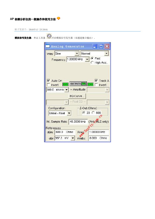
AP音频分析仪的一般操作和使用方法贴子发表于:2010/3/15 23:20:01模拟信号发生器:单击工具条开启模拟信号发生器(双通道独立输出)。
•Wfm: 选择产生信号波形。
一般测量使用Sine / Normal(典型正弦波波形),是由模拟部分硬件产生的低失真度的信号,20Hz –20KHz时失真度< 0.0001%。
•Frequency: 设定信号频率,Sine / Normal模式下可设定频率范围:10Hz –204KHz。
输入时可加单位“k(千)”。
•Fast / High Acc.: 选择快速(+/-0.5%)或高精度(+/-0.03%)模式。
快速模式适合于一般音频测试,建议在需高速自动测试中使用。
高精度模式产生精确的信号频率,但需150mS –750mS的设定反应时间,建议手动测试时选用此模式提高测量精度。
•Amplitude: 设定信号振幅。
平衡输出时可设定振幅:<10uV –13.33Vrms。
非平衡输出时可设定振幅:<10uV –26.66Vrms。
输入时可加单位“n(纳),u(微),m(毫)”。
注意因信号发生器的输出阻抗的差异,和DUT输入阻抗的差异,会导致DUT输入端的信号电压偏低于APWIN的设定电压。
•OUTPUT ON/OFF: 信号发生器输出开关。
按钮绿色是开启,灰色是关闭。
•Auto On: 如选中,在扫频开始时自动开启信号发生器,结束时自动关闭信号发生器。
•CHA On/Off: A通道输出开关。
按钮绿色是开启,灰色是关闭。
作用在信号发生器输出开关前。
•CHB On/Off: B通道输出开关。
按钮绿色是开启,灰色是关闭。
作用在信号发生器输出开关前。
•Invert: 信号相位180度反转。
可分别控制A / B通道。
通常反转B通道相位用于Dolby ProLogic测量。
•Track A: 如选中则同时设定A / B通道的振幅,反之分别设定。
•EQ Curve: 选用APWIN或自定的均衡器曲线。
Apx525使用说明+功能
图 12 监视器
10
APx525使用说明 APx525 提供了一系列监视器去显示详细的信号输入和其他数据 的信息,并且不会修改当前测量的视图。 监视器分为七种,下面分别对其进行介绍: (1)、Scope Monitor (范围监视器): 范围监视器提供了一种显示 XY 图形的示波器视图。 (2)、FFT Spectrum Monitor( FFT 频谱监视器): FFT 频谱监视器提供了一种显示 XY 图形的频域谱视图。 (3)、Meters Monitor(米监视器): 米监视器通过以表格的形式显示每个通道的水平、 总谐波失真加 噪声、频率 (4)、Aux Control Monitor (辅助控制监视器) : 辅助控制监视器显示了当前设备的辅助控制出和入的状态位。 (5)、Metadata Monitor:Status Bits(数据监控:状态位) : 状态位的数据监控显示了在数字输入信号中通道状态位的数据 监控。 (6)、Metadata Monitor:HDMI (数据监控:高清晰度多媒体接口) : 使用高清晰度多媒体接口数据监视器前,必须安装 HDMI 操作 或者 HDMI+ARC 操作。 (7)、Bluetooth Monitor (蓝牙监视器): 蓝牙监视器显示一系列当前蓝牙连接区域的状态和当前的数据。
3
APx525使用说明 【 1】产品在开发测试阶段时,团队协作,测试资料共享是很重 要的; 【 2】、测试项目文件中包含信号连接路径, 测试项目,相关设置, 上下限和自动化测试序列等信息。
2、 APx525 说明
快速浏览: APx525 工作空间
菜单栏 工具栏 工具栏
测试向导
监视器
测量参数设置面板
9
APx525使用说明 电平、偏差进行测量。 (7)、Signal to Noise Ratio(信噪比):提供一种测量被测设备输出信 号的信噪比的方法。 ( 8)、 Crosstalk(串音):防止正在被激励的通道受激励设备通道的 影响。 (9)、Interchannel Phas(e 相位):提供一种被测设备通道间相关联的 相位的测试方法。 (10)、Add Measuremen(t 增加测量步骤):还可以对以上的测量步 骤进行增加。 除了以上的信号路径设置以外还可以通过 Add Signal Path 增加信号 路径,设置完成以上步骤以后,通过 Report 查看序列的结果,并通 过 Data Output 将数据导出。
Microsoft Word - APx525测试仪操作说明
APx525测试仪操作说明1.双击打开桌面AP测试软件;2.测试参数前的设置。
(1)点击右侧菜单Signal Path Setup,在打开的界面选择相应测试端口,如下图所示(2)选择input/output下拉菜单,选中references项,修改input refercens中的阻抗和频率选项。
如下图修改完成之后,点击Generator off 变成Generator on,检测有无信号输出与被测机型的频率一致3.测试失真THD+N Ratio与功率RMS Level参数选择右侧菜单Stepped Level Sweep项。
(1)修改测试频率如下图此处与前面步骤2.(2)参考设置的频率要一致。
(2)调整点数Points,使得Step Size的值不大于3mVms,如图所示。
(3)两通道分开扫描:首先关闭通道2,点击start扫描出通道1的曲线;然后勾选Append Graph Data,同样的方法扫描出通道2的曲线。
点击start键开始扫描曲线此状态表示关闭通道2打开通道1.勾选Append GraphData添加通道2的曲线正在扫描通道2的曲线。
(4)失真THD+N Ratio与功率RMS Level曲线如下图如图可看出输入灵敏度和输出功率:X值为输入灵敏度,Y值是功率值。
4.测试失真度THD在Signal Path Setup 中找到THD+N Ratio,点开测试界面如下图。
输入上面测试的灵敏度的值,点击Generator off 变成Generator on,如下图。
5.测试信噪比找到Signal to Noise Ratio 输入灵敏度,点击start,如下图。
这里输入灵敏度的值这里读出失真度与被测机型的频率一致6.测试通道分离度找到Crosstalk,界面如图,输入通道灵敏度,点击start读数。
若选择A-wt.测试的是计权的值。
7.测试输出噪音找到Noise(RMS),直接读数。
apx500音频分析仪使用简易图解
APX 测试简易手册c信号路径的设置蓝牙播放器测试1.在信号源路径中选择bluetooth.2.点击settings 进行配对连接。
3.选择A2DP Source HSP4.点击Scan for devices 搜索被测产品5.点击pair 进行配对6.连接A2DP 协议7.开始测试相关测试项目c蓝牙主机(Audio Gateway)的测试1.Input Configuraton 路径设置为bluetooth2.点击settings 进行配对连接。
3.选择A2DP link ( Hand-free 或者headset)4.点击Scan for devices 搜索被测产品5.点击pair 进行配对6.连接A2DP 协议7.开始测试相关测试项目c功放测试1.根据实际接线,设置信号源的输出信号方式2.根据实际接线,设置分析仪的输入信号方式cDVD、CD的测试1.信号源设为none2.分析仪接口设置与实际接线方式一致。
c选择测试项目根据测试需求增加项目cc电平测试1.设置信号源输出波形2.设置信号源大小3.设置信号源频率4.打开信号源开关5.读取测量值c失真测试1设置信号源输出波形,2设置信号源大小3设置信号源频率4打开信号源开关c5按需求设置滤波器6读取测量值信噪比测试1设置信号源输出波形2设置信号源大小3设置信号源频率4打开信号源开关c5按需求设置滤波器6读取测量值频率扫描测试1.设置信号源波形2.设置信号源大小3.设置信号源开始频率,结束频率,扫描点数4.设置滤波器c5.点击Start 开始测试。
总谐波失真加噪声频率扫描测试1设置信号源波形2设置信号源大小3设置信号源开始频率,结束频率,扫描点数c4设置滤波器5 点击Start 开始测试生成测试报告cc。
Apx525使用说明+功能
Apx525使用说明目录1、APx525简介 (1)1.1 APx525简介 (1)1.2 APx525功能 (2)1.3 APx525优点 (2)2、APx525说明 (4)2.1 菜单栏 (5)2.2 工具栏 (7)2.3 测试向导 (8)2.4 监视器 (10)2.5 状态栏 (11)2.6 测量参数设置面板 (12)2.7 条形图面板 (16)2.8结果设置栏 (17)2.9 选择器 (18)1、APx525简介1.1 APx525简介APx525是2通道实时输入,输出快速音频分析仪,操作非常方便,简单。
不需要掌握很多的音频测量和编程经验,就能进行测试和编程操作。
大量测试项目模板已固化在电脑上,只需要选择你所需要的测试项目和要求,就可以产生自动化测试程序,自动产生各种格式的综合报告,包括图形,数字,也可以添加产品标记和公司名称。
APx是高速、高性能和友善用户而设计的。
创新发明包括“一按”测试,自动检测执行器,连续扫频技术等等,令测试17项数据只需约7秒。
APx525带2个平衡和2个不平衡输入和输出,在加上192K采样数字接口,有AES/EBU,TOSLINK光纤和SPDIF格式。
APx提供快,一按测试,结果可一页显示,数据,图形都带上下限自动检查。
通过智能对话选择,可非常快速和简单地选择滤波器和高级设定。
对于重复测试不同的输入和输出途径,可完全自动化执行,也可实时监查电平,波形和FFT频谱分析。
其他特别波形,例如方波和粉红噪声等等,可通过Apx的外置源模式播波,以测试CD、DVD和MP3播放机。
在大功率功放测试时,自动测量连续最大输出和峰值,可检视功率图谱和调控扫频,和其他符合CEA-2006和CEA-490A国际标准的测试。
APx突破性地产生信号低至0.1Hz,最大输入电压至300Vrms有效值(160V不平衡输入)和典型失真THD+N<-108(在1KHz,2.5V),没有其他同档次的产品有此高表现。
APx555音频分析仪音频测试仪操作说明书
• 步径扫频需要在Add mearsurement 里面添加 Stepped Frequency Sweep
APx Training 深圳市愛普泰科電子有限公司
Slide 18
• 起始電壓 • 結束電壓
• 掃描點數 • 掃描信號頻率
•资料仅供参考
測試步驟二之幅度掃描參數設置
• 低通,高通, 加權濾波器
o 1K to 1M o 平均处理 o 窗函数 o AC/DC 耦合
• 信号电压表
o 电平 o 总谐波失真加噪声 THD+N o 频率
• Status Bit信息
數字信號元數據的狀態位
• Aux控制口 • 特点:
o 独立地实时显示 o 可变尺寸
APx Training 深圳市愛普泰科電子有限公司
信號監視
注意: 對於所選擇的每個音頻測試參數, 都
需要對其進行對應的測試參數設置, 即每個測 試參數都有獨立的參數設置
APx Training 深圳市愛普泰科電子有限公司
Slide 17
• 起始頻率 • 結束頻率
•资料仅供参考
測試步驟二之頻率掃描參數設置
• 掃描點數 • 掃描電壓 • 低通, 高通, 加權濾波器
• 2通道或8通道輸出
• 平衡,非平衡輸入/輸出接口
• 正弦波信号 0.001Hz 到 80.1 kHz,Apx555可达 到204kHz, 频率精准度 3 ppm
• 正弦波输出电压 :1.0 uV to 26.66 V (平衡) 或 者 :1.0 uV to 13.33 V (非平衡). 精度约为 0.05 dB(不同型號儀器輸出能力有區別)
APx Training 深圳市愛普泰科電子有限公司
Slide 16
- 1、下载文档前请自行甄别文档内容的完整性,平台不提供额外的编辑、内容补充、找答案等附加服务。
- 2、"仅部分预览"的文档,不可在线预览部分如存在完整性等问题,可反馈申请退款(可完整预览的文档不适用该条件!)。
- 3、如文档侵犯您的权益,请联系客服反馈,我们会尽快为您处理(人工客服工作时间:9:00-18:30)。
• 共模抑制比 CMRR IEC-60628 • 直流偏移 DC LEVEL • 最大輸出功率-BURST • 聲學參數測量 SPL,THD • 數字信號誤碼分析 • HDMI 數字音頻分析(HDMI Option) • 芯片級別的數字信號分析(DSIO Option) • 藍牙音頻傳輸性能指標 • PDM脈衝密度調制碼流音頻指標 • PESQ聲音質量指數評估
• 具有过载保护功能
非平衡輸出, 主要用於消費類音頻領域
平衡方式輸出, 主要用於專業音頻領域 兩通道/四通道系列硬件
八通道系列硬件
模拟输入模块
• 2通道,4通道或8通道輸入 • 平衡、非平衡輸入接口 • 输入信号范围 0.32 V 到300 V (根據儀器型號) • 输入阻抗 100 kΩ 或者600 Ω| • 共模抑制比CMRR ≥80 dB, 5 Hz to 5 kHz • 串音
非平衡输入,主要用于消费类音頻
平衡输入,主要用于专业音响、广播领域 兩通道/四通道系列硬件
八通道系列硬件
數字輸入/輸出模塊
• 數字接口類型
Balance: AES3,EBU-3250,IEC60958-4
Unbalance: AES3-id,SPDIF, IEC60958-3
• 數字音頻格式
• Linear PCM 格式輸出 • Dolby, DTS等編碼格式輸出(加載信
APx500 Series Option
HDMI option
DSIO option
Bluetooth
AUX-0100
PDM
模擬輸出模塊
• 2通道或8通道輸出
• 平衡,非平衡輸入/輸出接口
• 正弦波信号 0.001Hz 到 80.1 kHz,Apx555可达到 204kHz, 频率精准度 3 ppm
APx Training
APx Technical Presentation
Latest updated: 12st , Dec,2014 Kevin.Tao
APx500系列音频分析仪 两通道模擬輸出, 兩通道或以上的模拟输入接口
线性编码数字音频接口(AES/EBU, TOSLINK, SPDIF) Linear PCM
測試步驟一之信號路徑設置
• 任何測試開始前
• Signal path setup 信號路 徑設置
①輸入/輸出(平衡、非平衡) ②通道數 2通道 ③測試帶寬設置
• 檢驗各項設置
• 提供檢驗設置是否正確的 方法
• 打開Generator開關 • 檢查輸出是否正確,如果
• 平衡方式 >90 dB to 20 kHz • 非平衡方式 >100 dB to 20 kHz
• 电平
• 范围 <1 uVrms to 110 Vrms • 精度 (1 kHz) ±0.05 dB • 平坦度 ±0.008 dB 10 Hz to 20 kHz
• 噪声成分
• 20 kHz Low Pass ≤ 1.3 uVrms (-115.5 dBu)
• 正弦波输出电压 :1.0 uV to 26.66 V (平衡) 或 者 :1.0 uV to 13.33 V (非平衡). 精度约为 0.05 dB(不同型號儀器輸出能力有區別)
• 能够产生正弦波信号,IMD信号,连续扫描信号、 方波等
• 可以加載存儲在本地電腦的波形文件 (wav,ac3,ec3, etc.)
• 适用音頻分析儀
APx515 APx520, APx521 APx525 APx526 APx585 APx586 APx555
測量功能
• 輸出電壓 LEVEL • 總諧波失真 THD+N • 頻率響應 FREQUENCY RESPONSE • 分離度 CROSSTALK • 信噪比 SNR • 相位 PHASE • 互調失真 DIM,DFD,MOD,
號) • 支持8bit-24bit的數字音頻 • 采样率
• 范围 22 kHz to 192 kHz • 精度 ±0.0003% [3 PPM]
• HDMI數字音頻(HDMI選件) • I2S數字音頻(DSIO選件) • PDM 脈衝密度調制信號(PDM選件) • Bluetooth藍牙音頻(BT選件)
BW52选件:超高带宽分析仪选件,带宽高达1MHz ADIO选件:Apx555标配,输入接口测试,Jitter 信号发生器 DSIO选件:用来进行芯片级别的数字信号测试,如I2S HDMI选件:增加HDMI接口到音频分析仪,用来分析具有HDMI接口的音频设备 PDM選件: 增加PDM碼流產生及分析功能; BT選件: 增加藍牙音頻產生以及分析功能; PESQ選件: 增加語音質量評估功能選件(軟件) SW-SPK-PT/RD:增加扬声器,麦克风生产线以及开放版声学测试功能(软件)
測試類型
• 閉環測B試alance
信號發生 Un-balance
被測設備
Balance Un-balance
信號分析
標準音頻文件
• 開環試 (MP3, WAV, AC3等)
被測設備
Balance Un-balance
信號分析
Bench Model
•D
APx500 基本測試步驟
測試步驟一
• 信號路徑設置 • 參考數據設置 • 音頻測試參數選擇
脈衝密度調制碼流PDM(需APx-PDM選件支持)
Bluetooth藍牙音頻碼流(需APx-BT選件支持)
最高支持192 kHz 数字采样音频(Apx555最高支持216kHz)
Apx500 V4.0新增Bench 模式,有效帮助工程师进行开发调试
快速测量
可選操模作塊简单方便,一键测试,产生多种图形,产生测试报告 AG标52选准件的:增US加B方接波口信与号、PDCI通M測讯試信號产生功能
平衡方式 支持AES3,EBU-3250,IEC60958-4
非平衡方式 支持AES3-id,SPDIF,IEC60958-3
HDMI 選件
DSIO 選件
APx500量測系統組成
• APx500 V4.0 控制軟 件
• 控制電腦系统要求
Windows 7以上 2GHz CPU或更高 2G內存或更高 USB2.0