Event detection services using data service middleware in distributed sensor networks
win10服务详解
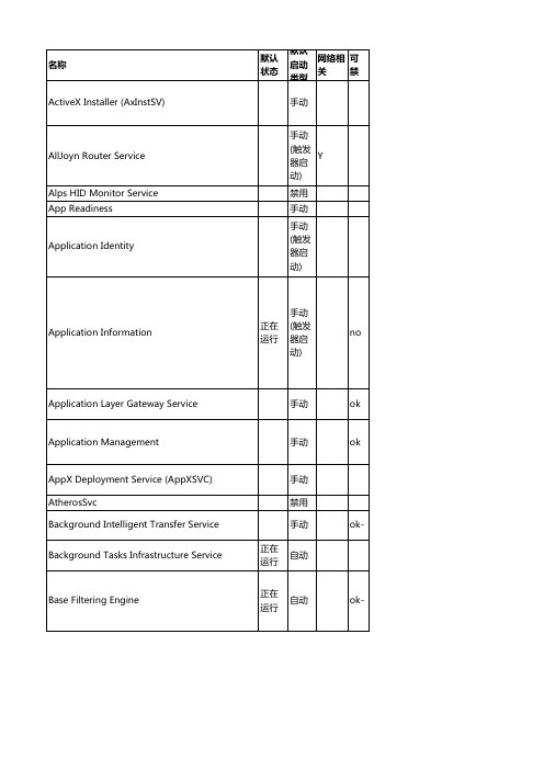
Bluetooth Handsfree Service BranchCache CDPUserSvc_347a0 Certificate Propagation Client License Service (ClipSVC)
CNG Key Isolation COM+ Event System COM+ System Application
手动
(触发 器启
Y
动)
手动
正在 运行
(触发 器启
Y
ok-
动)
手动 Y
no
手动 (触发 器启 动)
正在 运行
手动 Y
no
Network Location Awareness
正在 运行
自动 Y
no
Network Setup Service
Network Store Interface Service Office 64 Source Engine Office Software Protection Platform
手动
(触发 器启
Y
no
动)
正在 运行
手动 (触发 器启 动)
手动 (触发 器启 动)
手动 (触发 器启 动)
手动 (触发 器启 动)
手动 (触发 器启 动)
手动 (触发 器启 动)
手动 (触发 器启 动)
手动 (触发 器启 动)
手动 (触发 器启 动)
手动 (触发 器启 动)
IKE and AuthIP IPsec Keying Modules
手动
手动
(触发 器启
FortiADC 产品数据表说明书
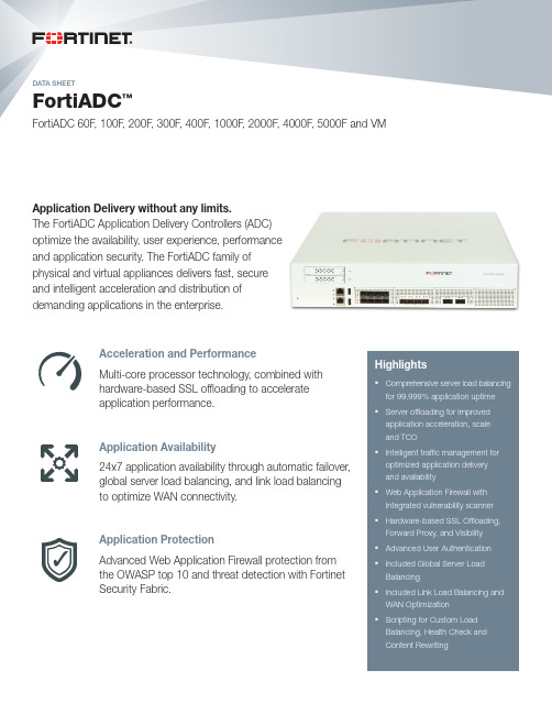
DATA SHEETFortiADC ™FortiADC 60F , 100F , 200F , 300F , 400F , 1000F , 2000F , 4000F , 5000F and VMHighlights§Comprehensive server load balancing for 99.999% application uptime §Server offloading for improved application acceleration, scale and TCO§Intelligent traffic management for optimized application delivery and availability§Web Application Firewall with Integrated vulnerability scanner §Hardware-based SSL Offloading, Forward Proxy, and Visibility §Advanced User Authentication §Included Global Server Load Balancing§Included Link Load Balancing and WAN Optimization §Scripting for Custom Load Balancing, Health Check and Content RewritingApplication Delivery without any limits.The FortiADC Application Delivery Controllers (ADC) optimize the availability, user experience, performance and application security. The FortiADC family of physical and virtual appliances delivers fast, secure and intelligent acceleration and distribution of demanding applications in the enterprise.Acceleration and PerformanceMulti-core processor technology, combined with hardware-based SSL offloading to accelerate application performance.Application Availability24x7 application availability through automatic failover, global server load balancing, and link load balancing to optimize WAN connectivity.Application ProtectionAdvanced Web Application Firewall protection from the OWASP top 10 and threat detection with Fortinet Security Fabric.DATA SHEET | FortiADC ™2HighlightsHardware-Based SSL Offloading, SSL Inspection, and VisibilityFortiADC offloads server-intensive SSL processing with support for 4096-bit keys, TCP connection management, data compression and HTTP request processing from servers. This speeds up response times, reduces load on the backend servers, allowing them to serve more users.SSL Forward Proxy utilizes FortiADC’s high-capacity decryption and encryption to allow other devices, such as a FortiGate firewall, to easily inspect traffic for threats. An inline pair of FortiADCs at the front end and back end of a firewall remove all encryption so that the firewall isn’t taxed with the additional load of SSL processing. FortiADC ensures seamless re-encryption with certificates intact with no user disruptions.FortiADC’s Transparent HTTP/S and TCP/S Mirroring Capabilities decrypt secure traffic for inspection and reporting. Copies of clear traffic can be sent for analysis by FortiGate or other third-party solutions for an indepth view of threats that may be hidden in encrypted traffic while FortiADC continues to perform its application delivery functions.FortiADC integrates with Gemalto’s SafeNet Enterprise Hardware Security Modules (HSMs) to use the advanced security certificates managed by the HSM for the encryption and decryption of secure application traffic. This lets organizations that use Gemalto’s SafeNet HSMs deploy a high-performance ADC solution using a strong, centrally-managed set of certificates and encryption keys.Disaster Recovery with Global Server Load BalancingFortiADC’s included Global Server Load Balancing (GSLB) makes your network reliable and available by scaling applications across multiple data centers for disaster recovery or to improve application response times. Administrators can set up rules that direct traffic based on site availability, data center performance and network latency.Web Application FirewallFortiADC offers multiple levels of protection to defend against attacks that target your web applications. FortiADC Web Application Firewall can detect a zero day attack and protect from OWASP top-10 and many other threats with multi-vector protection such as SQLi and XSS Protection, Web Scraping, Brute Force, Web Defacement, Protocol Validation (HTTP RFC) and Web Attack Signature using FortiGuard WAF Security Services for layer 7 attacks (subscription required). Also, FortiADC WAF provides full Web Vulnerability Scanning for your website to detect and alert against known attacks.Optimize Performance with PageSpeed, Caching, and CompressionFortiADC provides multiple services that speed the delivery of applications to users. The PageSpeed suite of website performance enhancement tools can automatically optimize HTTP , CSS, Javascript and image delivery to application users. Caching on FortiADC dynamically stores popular application content such as images, videos, HTML files and other file types to alleviate server resources and accelerate overall application performance. HTTP Compression employs GZIP and DEFLATE to intelligently compress many content types used by today’s latest web-based applications to reduce bandwidth needs and improve the user application experience.Deep Integration into the Fortinet Security FabricAs the threat landscape evolves, many new threats require a multi-pronged approach for protecting applications. Advanced Persistent Threats that target users can take many different forms than traditional single-vector attack types and can evadeprotections offered only by a single device. FortiADC’s antivirus and integration with FortiSandbox extend basic security protections toscan file attachments for known and unknown threats.DDoS Application, Web Filtering, IPS, Geo-IP and IP Reputation for Enhanced SecurityFortiGuard Web Filtering works with FortiADC’s SSL Forward Proxy feature to simplify the process of managing exceptions for secure traffic inspection. Instead of manually configuring single URLs, Web Filtering gives administrators the ability to choose websitesDATA SHEET | FortiADC™HighlightsAdvanced Layer 7 Load Balancing Intuitive L7 policy-based routing to dynamically rewrite content to support complex applications andserver configurations.Web Application Firewall Advanced Web Application Firewall that protects applications with Web Application Attack Signatures,Protocol Validation, Web Vulnerability Scanner, Bot Detection, DLP and File Restriction.SSL Offloading, Forward Proxy,and VisiblityHardware and software-based SSL offloading reduces the performance impact on your server infrastructure.Also provides SSL visibility, decryption and re-encryption for FortiGate to easily inspect traffic for threats.Application Optimization Speed up web application delivery with Compression, Caching, HTTP 2.0, and HTTP Page Speed-UP forimproved network and web server utilization.Global Server Load Balancing Included Global Server Load Balancing distributes traffic across multiple geographical locations for disaster Key Features and Benefitsby category type to enable or disable SSL traffic inspection as agroup instead of on a site by site basis. FortiADC also supports ourFortiGuard which provides multi services such as: IPS, Antivirusand IP Reputation service (subscription required) that protectsyou from sources associated with DoS/DDoS attacks, phishingschemes, spammers, malicious software and botnets.Scripting to Extend Built-in FeaturesFortiADC’s Lua-based scripting language gives you the flexibilityto create custom, event-driven rules using predefined commands,variables and operators. Using easy-to-create scripts, you get theflexibility you need to extend your FortiADC with specializedbusiness rules that give you almost unlimited possibilities for serverload balancing, health checks, application validation, content routing,and content rewriting to meet the needs of your organization.Link Load BalancingBuilt-in Link Load Balancing (LLB) gives you the option to connectyour FortiADC to two or more WAN links to reduce the risk ofoutages or to add additional bandwidth to relieve traffic congestion.FortiADC supports inbound and outbound Link Load Balancing tomanage traffic leaving or entering the device. Using policy routing,FortiADC can support complex NAT and routing requirements toaddress almost any network LLB architecture. With Tunnel Routingyou get high-speed, reliable site-to-site connectivity without theneed to lease expensive WAN links. It aggregates multiple linksto create a virtual tunnel to a remote data center that ensuresavailability especially for applications that are time sensitive andrequire large single-session bandwidth such as video conferencing.Analytics and VisibilityFortiADC offers real-time and historical information about yourappliance, which includes the logical topology of real-server pools,user/application data-analytics, security threats, attack maps andsome other system events and alerts.FortiADC DashboardVM and Public Cloud OptionsFortiADC provides maximum flexibility in supporting your virtual andhybrid environments. The virtual versions of FortiADC support all thesame features as our hardware-based devices and can be deployedin VMware, Microsoft Hyper-V, Citrix XenServer, Open Source Xen,and KVM platforms. FortiADC is also available for Amazon WebServices, Microsoft Azure, Google Cloud and Oracle Cloud.DATA SHEET | FortiADC™4Global Server Load Balancing (GSLB)§Global data center DNS-based failover of web applications§Delivers local and global load balancing between multi-site SSL VPN deployments§DNSSEC§DNS Access Control Lists§GSLB setup wizardDeployment Modes§One arm-mode (Proxy with X-forwarded for support)§Router mode§Transparent mode (switch)§High Availability (AA/AP Failover)Web Application FirewallApplication Protection§OWASP Top 10§Web Attack Signature§Bot Detection§Web Vulnerability Scanner§HTTP RFC complianceSecurity Services§SQLi/XSS Injection Detection§Web Scraping§CSRF Protection§Brute Force Protection§Web Defacement Protection§Data Leak Prevention§File Restriction§Cookie Security§XML/JSON/SOAP Validation§HTTP Header SecurityApplication AvailabilityEasy to use and configure Layer 4/7 policy andgroup management§Virtual service definition with inherited persistence, load balancing method and pool members§Static, default and backup policies and groups§Layer 4/7 application routing policy§Layer 4/7 server persistence§Application load balancing based on round robin, weighted round robin, least connections, shortest response§Granular real server control including warm up rate limiting and maintenance mode with session ramp down§Custom Scripting for SLB and Content Rewriting§Application Templates for Microsoft Applications including SharePoint, Exchange and Windows Remote Desktop§Application and script health checks§Clone Traffic PoolsLayer 4 Application Load Balancing§TCP, UDP stateless protocols supported§Round robin, weighted round robin, least connections, shortest response§L4 dynamic load balancing based on server parameters (CPU, Memory and disk)§Persistent IP, has IP/port, hash header, persistent cookie, hash cookie, destination IP hash, URI hash, full URI hash, host hash, host domain hashLayer 7 Application Load Balancing§DNS, HTTP, HTTPS, HTTP 2.0 GW, FTP, SIP, RDP, RADIUS, MySQL, RTMP, RTSP supported§L7 content switching– HTTP Host, HTTP Request URL, HTTP Referrer– Source IP Address§URL Redirect, HTTP request/response rewrite (includes HTTP body)§Layer 7 DNS load balancing, security, and caching§403 Forbidden Rewrite§Content rewritingLink Load Balancing§Inbound and outbound LLB§Support for Policy Route and SNAT§Multiple health check target support§Configurable intervals, retries and timeouts§Tunnel RoutingFeaturesDATA SHEET | FortiADC ™5FeaturesApplication AccelerationSSL Offloading and Acceleration§Offloads HTTPS and TCPS processing while securing sensitive data§Full certificate management features§SSL Forward Proxy for secure traffic inspection §HTTP/S Mirroring for traffic analysis and reporting §Support TLS 1.3HTTP and TCP Optimization§100x acceleration by off-loading TCP processing§Connection pooling and multiplexing for HTTP and HTTPS §HTTP Page Speed-UP for Web Server Optimization and Acceleration §TCP buffering§HTTP Compression and Decompression §HTTP Caching (static and dynamic objects) §Bandwidth allocation with Quality of Service (QoS) §HTTP and Layer 4 Rate Limiting Authentication Offloading §Local §LDAP §RADIUS §Kerberos§SAML 2.0 (SP & Idp)§Two-Factor Authentication — FortiToken and Google AuthenticationNetworking§NAT for maximum flexibility and scalability §VLAN and port trunking support§Cisco ACI, Nutanix, OpenStack and Ansible §NVGRE and VXLAN Support§BGP and OSPF with Route Health Inspection (RHI) §IPv6 Support §IPv6 routing §IPv6 firewall rulesApplication Security§FortiGuard Antivirus and FortiSandbox integration §GEO IP security and logs (subscription required) §Stateful firewall§Web Filtering (subscription required) §IP Reputation (subscription required) §IPv4 and 6 firewall rules§Granular policy-based connection limiting §Syn Cookie Protection §Connection Limits§Intrusion Prevention System (subscription required) §Application DDoS Protection §DNS SecurityManagement§Single point of cluster management§CLI Interface for configuration and monitoring §Secure SSH remote network management §Secure Web UI access§Central management for multiple FortiADC devices §RESTful API§SNMP with private MIBs with threshold-based traps §Real-time Data Analytics §Syslog support§Role-based administration §In-build diagnostic utilities §Real-time monitoring graphs §Built-in reporting§FortiView Integration §Data Analytics§Getting Started wizard for first-time login §Virtual Domains (VDOMs)DATA SHEET | FortiADC ™6SpecificationsHeight x Width x Length (mm)38 x 216 x 16044 x 440 x 26844 x 432 x 301.4Weight2.2 lbs (1 kg)9.9 lbs (4.5 kg)10.98 lbs (4.98 kg)All performance values are “up to” and vary depending on the system configuration.* Layer 7 CPS — measures number of new HTTP connections (1 HTTP request per TCP connection)** Tested with 1 HTTP request per SSL connection; SSL Ciphers=AES256-SHA; 2K KeysFortiADC 100FFortiADC 200FFortiADC 60FDATA SHEET | FortiADC ™7SpecificationsHeight x Width x Length (mm)44 x 438 x 41644 x 438 x 41644 x 438 x 530 Weight20 lbs (9.07 kg)20 lbs (9.07 kg)22.6 lbs (10.3 kg)All performance values are “up to” and vary depending on the system configuration.* Layer 7 CPS — measures number of new HTTP connections (1 HTTP request per TCP connection) ** Tested with 1 HTTP request per SSL connection; SSL Ciphers=AES256-SHA; 2K KeysFortiADC 1000FFortiADC 400FFortiADC 300FDATA SHEET | FortiADC ™8Height x Width x Length (mm)44 x 438 x 530 88 x 438 x 53080.6 x 436.9 x 777.2Weight22.6 lbs (10.3 kg)27 lbs (12.25 kg)68.3 lbs (31 kg)All performance values are “up to” and vary depending on the system configuration.* Layer 7 CPS — measures number of new HTTP connections (1 HTTP request per TCP connection) ** Tested with 1 HTTP request per SSL connection; SSL Ciphers=AES256-SHA; 2K Keys *** Subject to availabilitySpecificationsFortiADC 2000FFortiADC 4000FFortiADC 5000FDATA SHEET | FortiADC™SpecificationsHardware SpecificationsHypervisor Support VMware ESX/ESXi, Citrix XenServer, Open Source Xen, Microsoft Hyper-V, KVM, AWS, Azure, Google Cloud, Oracle Cloud. Please see the FortiADC-VM Install Guide for thelatest hypervisor versions supported.L4 Throughput* 1 Gbps 2 Gbps 4 Gbps10 Gbps16 Gbps24 GbpsVirtual Domains005101520vCPU Support (Maximum)12481632Memory Support (Maximum) 4 GB 4 GB8 GB16 GB32 GB64 GBNetwork Interface Support (Maximum)101010101010Storage Support (Minimum / Maximum)50 MB / 1 TB50 MB / 1 TB50 MB / 1 TB50 MB / 1 TB50 MB / 1 TB50 MB / 1 TB Throughput Hardware Dependent Hardware Dependent Hardware Dependent Hardware Dependent Hardware Dependent Hardware Dependent Management HTTPS, SSH CLI, Direct Console DB9 CLI, SNMP*********************************************************************************************************************************************************************************.5.Order Information Copyright © 2019 Fortinet, Inc. All rights reserved. Fortinet®, FortiGate®, FortiCare® and FortiGuard®, and certain other marks are registered trademarks of Fortinet, Inc., and other Fortinet names herein may also be registered and/or common law trademarks of Fortinet. All other product or company names may be trademarks of their respective owners. Performance and other metrics contained herein were attained in internal lab tests under ideal conditions, and actual performance and other results may vary. Network variables, different network environments and other conditions may affect performance results. Nothing herein represents any binding commitment by Fortinet, and Fortinet disclaims all warranties, whether express or implied, except to the extent Fortinet enters a binding written contract, signed by Fortinet’s General Counsel, with a purchaser that expressly warrants that the identified product will perform according to certain expressly-identified performance metrics and, in such event, only the specific performance metrics expressly identified in such binding written contract shall be binding on Fortinet. For absolute clarity, any such warranty will be limited to performance in the same ideal conditions as in Fortinet’s internal lab tests. Fortinet disclaims in full any covenants, representations, and guarantees pursuant hereto, whether express or implied. Fortinet reserves the right to change, modify, transfer, or otherwise revise this publication without notice, and the most current version of the publication shall be applicable. Fortinet disclaims in full any covenants, representations, and guarantees pursuant hereto, whether express or implied. Fortinet reserves the right to change, modify, transfer, or otherwise revise this publication without notice, and the most current version of the publication shall be applicable.FST-PROD-DS-ADC3FAD-DAT-R36-201908。
翻译1 英文
GSM Infrastructure Used for Data TransmissionConstantin Daniel Oancea, Member, IEEEPolitehnica University of Bucharest, Bucharest, RO 060042, Romaniadaniel.oancea@upb.roAbstract- In cellular service there are two main competingnetwork technologies: Global System for MobileCommunications (GSM) and Code Division Multiple Access(CDMA). Since its beginning in the '80s, GSM telephone systemwas developed using cell concept for the network topology. Each cell corresponds to a specific antenna (base station), placed on towers or tall buildings. The GSM standard has been an advantage to both consumers, who may benefit from the ability to roam and switch carriers without replacing phones, and also to network operators. GSM also has low-cost implementation of the short message service (SMS), also called text messaging,which has since been supported on other mobile phonestandards as well. Because of huge coverage of distance, the GSM infrastructure can be an alternative to transmit or receive data from or to a device (sensor, actuator, complex device) near or remotely. Compared to analog transmission systems, GSM system provides narrowest bandwidth for a channel, through the use of voice compression algorithm; improving the quality of transmission by using detection and correction codes of errors; digital signal encryption to ensure security and protection against unwanted interception. To illustrate and analyze the possibilities of data transmission using GSM infrastructure is considered the situation of a remote monitoring system (photovoltaic panels) without the ability to connect to the Internet via cable or other options (transmission trunking radio system or Wi-Fi Internet Access Point or satellite). The only possibility is the presence of GSM signal, but this not require high quality signal because was used a short messaging service (SMS) for communication. The unit consists of computing (computer + software application), a device or more (any measuring device that can connect to the computer) and a GSM terminal (telephone modem capabilities or GSM modem). The system is bidirectional in that the nformation is not only moving from GSM mobile phone to GSM modem, but can also give information to mobile phone.I. INTRODUCTIONHistory of GSMDuring the early 1980s, analog cellular telephone systems were experiencing rapid growth in Europe, particularly in Scandinavia and the United Kingdom, but also in France and Germany. Each country developed its own system, which was incompatible with everyone else's in equipment and operation. This was an undesirable situation, because not only was the mobile equipment limited to operation within national boundaries, which in a unified Europe were increasingly unimportant, but there was also a very limited market for each type of equipment, so economies of scale and the subsequent savings could not be realized.The Europeans realized this early on, and in 1982 the Conference of European Posts and Telegraphs (CEPT) formed a study group called the Groupe Spécial Mobile (GSM) to study and develop a pan-European public land mobile system. The proposed system had to meet certain criteria:Good subjective speech qualityLow terminal and service costSupport for international roamingAbility to support handheld terminalsSupport for range of new services and facilitiesSpectral efficiencyISDN compatibilityIn 1989, GSM responsibility was transferred to the European Telecommunication Standards Institute (ETSI), and phase I of the GSM specifications were published in 1990. Commercial service was started in mid-1991, and by 1993 there were 36 GSM networks in 22 countries [6]. Although standardized in Europe, GSM is not only a European standard. Over 200 GSM networks (including DCS1800 and PCS1900) are operational in 110 countries around the world. In the beginning of 1994, there were 1.3 million subscribers worldwide [18], which had grown to more than 55 million by October 1997. With North America making a delayed entry into the GSM field with a derivative of GSM called PCS1900, GSM systems exist on every continent, and the acronym GSM now aptly stands for Global System for Mobile communications. According to the GSM Association (external link) , here are the current GSM statistics:The developers of GSM chose an unproven (at the time) digital system, as opposed to the then-standard analog cellular systems like AMPS in the United States and TACS in the United Kingdom. They had faith that advancements in compression algorithms and digital signal processors would allow the fulfillment of the original criteria and the continual improvement of the system in terms of quality and cost. The over 8000 pages of GSM recommendations try to allow flexibility and competitive innovation among suppliers, but provide enough standardization to guarantee proper interworking between the components of the system. This is done by providing functional and interface descriptions for each of the functional entities defined in the system.GSM (Global System for Mobile Communications) is a digital mobile phone system, operating in several frequency bands. Most knowing bands are 900 MHz frequencies (GSM 900), 1800 MHz (GSM 1800) but also in the bands 1900 MHz and 2100 MHz, based on their own memory cards Called SIM (Subscriber Identity Module), which provides user identity to network with their telephone numbers assigned.GSM provides the highest quality data calls, and, moreover, offers the possibility of using the same mobile phone (with the same SIM card, and hence the same number)and other networks around the world (roaming) so that theuser can be found even if it is not in the country [1], [2]. The GSM network itself consists of the interconnected cells. Each cell corresponds to a specific antenna (base station), placedon towers or tall buildings to avoid a near-immediate access to their public persons.Thus, if a phone call made, being in motion, he can move from one cell to another, these cell coverage areas overlap, in order to ensure a high quality of the call, without distortion or interruption caused by lack of signal. The GSM system uses a combination of techniques access to radio channel:- frequency-multiplexing (FDMA - FrequencyDivision Multiple Access)- time-multiplexing (TDMA - Time Division Multiple Access).The main features of GSM were to be an international roaming capability, using small cheap handsets and the ability to handle high volumes of users. GSM was taken over in 1989 by ETSI (European Telecommunications Standards Institute) and they finalized the GSM standard in 1990. GSMservice started in 1991. The GSM network is composed of several hundreds of cell sites arranged overlapping one over the other, in such a way that produces radio broadcast coverage continues uninterrupted. During the call, the GSM terminal is connected by radio to the radio station located inthe area where the subscriber is located. When moving from one cell into another, the call is sent without the user carry out the process of transition from one channel to another [2]. Radio station has a range that can vary from at least 1 km, if it is an urban area, up to 30 km in other areas.II. MOBILE TELECOMMUNICATION NETWORK The GSM network is composed of three main parts, the mobile station (MS), base station transmitting – receiver (BTS) that controls the connection to the mobile station, base station control (BSC) which controls the base station transmitting - receiver and central office (MSC).A digital mobile phone with SIM card is a mobile station.SIM (Subscriber Identity Module) is a card that fits in receiver and is one of two sizes - either size (same size as a credit card) or small version of a piece. Microprocessor-based SIM card is a silicon chip that is designed to tolerate temperatures of -25 degrees Celsius to +70 degrees Celsius, and will also withstand higher humidity of 85%. However silicon is fragile and therefore if the card is tampered, physically and electronically, the card will become useless.Card contains all your identification details, like the IMSI(International Mobile Subscriber Identity). This is a numeric string, where the first three digits represent the country wherethe SIM was sale; the following is the operator in that country. The other numbers are the subscriber identity, phone memories, billing information, saved SMS, pin numbers and information about international roaming. A card IMEI (International Mobile Equipment Identity) is the serial number of the GSM phone, ESN (Electronic Serial Number), number that is equivalent in an analog phone; it is fixed in the phone and can not be changed. IMSI (International Mobile Subscriber Identity) SIM card contains a number that identifies the user to the network along with other user and security information. The mobile phone (mobile station),when the user initiates a call, take to the airwaves to call thempassing STDs (Subscribers Trunk Dialing). Calls made todifferent countries are called international calls or ISD [2].Base Transceiver Station (BTS) is a radio transmitterreceiver antenna covering a single cell.STDs are all connected together to allow you to move fromone cell to another.Base Station Controller (BSC) manages several STDs.Controls allocation and release of radio channels and handovers between cells.A number of BTS's are connected to each base station control. BSC supervises each call and decides when andwhere to send a STD call.Some sites are controlled by BSC-MSC, the MSC (Mobile Switching Center) works with four data base (HLR, VLR,EIR and AuC) and together they manage communications between a mobile station and other network user. Each database has its functions, as follows: Mobile SwitchingCenter (MSC).Change Central Office is the interface between the base station system and subsystem change mobile phone network. Furthermore, the MSC is also the interface between the cellular network and PSTN. MSC generates all billing records and ensure that full use should be directed to the appropriateaccount.MSC have a relatively complex duty as a conventionaltelephone exchange, when they call GSM subscribers couldbe anywhere in the network.III. GDW-11 485 GSM /GPRS MODEM AND ITS APPLICATIONGDW-11 modem provides a communication link between GSM/GPRS network. The modem has been designed for use in industrial data communications and has several features not normally found in standard GSM modems [3].GDW-11 can be used in applications with data transfer among other GSM modems, ISDN adapters, PSTN or analog modems. Data packets can be sent via GPRS.GDW-11 is a radio transmitter and receiver at low speed.When turned on, it receives and transmits radio frequency,RF. Most electronic equipment is protected against RF, but they may not be shielded against RF signals from a wireless unit.All transmitters emit radio signals, which can cause interference in other electronic equipment. To avoid interference, the antenna must be mounted as far away as possible from any electronic equipment. Description of the operation of the GSM modem is represented in fig. 1 [3].Fig. 1. Description of the operation of the GDW-11 GSM modemIV. CHOOSING AN IMPLEMENTATION SOLUTION To illustrate and analyze the possibilities of data transmission using GSM infrastructure is considered the situation of a remote monitoring system without the ability to connect to the Internet via cable or other options (transmission using trunking radio system or distributor Wi-Fi Internet access or satellite). For example photovoltaic panels must transmit information on demand or in special situation of voltage, current, temperature or luminance. The only possibility is the presence of GSM signal, but this claim without the latest technology. For example there is no need for technologies like CDMA, or 3G, or GPRS, and can be used for communication as short message service, SMS. This extends compatibility with most network operators.The unit consists of computing (computer + software application), the GSM terminal (telephone modem or GSM modem capabilities) and a tracking device or data logger (any measuring device that can connect to the computer). Figure 2 shows the system topology.Fig. 2. Description of the system topologyThe system is bidirectional in that the information is not only moving from GSM mobile phone to modem, but can also can give information to phone.Although can communicate with the modem through any program that cansend/receive via serial mode, these is impractical because this not ensure automate decisions. Thus,was used for developing NI LabVIEW programming environment [4],[5]. The application has to send the modem to text messages with information on preset limits is exceeded. For signals, SMS or call, there is an indicator that can be converted to external signal. The main requirements of the system are to send information about an event in the form of SMS and to take orders by phone call or SMS received from a mobile phone. The proposed application does not consider all possibilities, but provides an example of implementation, the final solution adapting to specific requirements. Sequential programming was chosen because it requires a sequence (initialization, building commands, etc.) in order [5], [6], [7]. Thus, identifying the modem is the first step, because the decision is taken and continues program execution [8].Fig. 3. Front panel of applicationThe main component of the system is the program that manages the entire activity. This front panel shown in fig. 3 has three sections: the top is the section devoted to software setup, size monitoring and control section of the modem and the last section is dedicated to information received from the modem.The application was referred to the possibility that both can work with the real signal from a meter interface, as well as a variable size generated by the program. Selection of these modes of operation of the switch is “Simulation/Acquisition”.It is present strength of radio signal indicator.The application principle is to send to the modem a text messages with information about preset limits are exceeded. The software decodes the SMS end extract information. For signals, SMS or call, there is an indicator that can be converted to external signal. The main requirements of the system are to sendinformation about an event in the form of SMS and to take orders by phone call or SMS received from a mobile phone. Figure 4 presents an example of a section of diagram block of application.Fig. 4. Diagram of GSM communication configuration sequence When send the information by modem, software build string using specific commands and send by mands are sequence of strings and how that is achieved is presented in figure 5.Fig. 5. Diagram of build string commandsThe application has to send to the modem text messages with information for example, on preset limits are exceeded,fig. 6.Fig. 6. Example of SMS received by phoneV. CONCLUSIONThe GSM network is composed of several hundreds of cell cells arranged overlapping one over the other, in such a way that produces radio broadcast coverage continues uninterrupted. Front Base Transceiver Station consists of a radio transceiver with antenna that covers a single cell.Message from the transmitter is routed to an SMS and on to the recipient. Each telephone network that supports SMS has one or more messaging centers to coordinate short messages. SMS is a service and reference memory (saved defined SMS).GDW-11 modem provides a communication link between GSM/GPRS network and monitoring system. The modem has been designed for use in industrial data communications and has additional several features not normally found in standard GSM modems. GDW-11 is a radio transmitter and receiver with low speed. When turned on, it receives and transmits radio frequency RF. Most electronic equipment is protected against RF, but they may not be shielded against RF signals from a wireless unit. For signals, SMS or call, there is an indicator that can be converted to external signal.The main requirements of the system are to send information about an event in the form of SMS and to take orders by phone call or SMS received from a mobile phone.The system is bidirectional in that the information is not only moving from GSM mobile phone modem, but can also give commands to mobile phone. Since communication is serial and has low speed (9600 baud), does not require special requirements of software timing. Virtual instruments references to read and write are connected in sequence,thereby establishing an order; a read operation is only after being made the command.The operation should consider that the power must be on after connecting themodem communication interface. The application provides a self-made monitoring system with ahigh degree of flexibility, being suitable for areas where Internet infrastructure is not present or when the use oftransceivers is not possible. The only condition for thefunctioning of this system is a GSM operator in the area, with no special requirements about the signal.Multiple Access• CLIP - Caller Line Identity Presentation• CLIR - Caller Line Identity Restriction• ESN - Electronic Serial Number• EIR - Equipment Identity Register• FDMA - Frequency Division Multiple Access• GMSC - Gateway Mobile Switching Center• GSM - Global System For Mobile Communication• HLR - Home Location Register• IMEI - International Mobile Equipment Identity; 15digit code used to identify the GSM phone to the network.• IMSI - International Mobile Subscriber Identity• MSC - Mobile Switching Centre - The computer thatplaces the calls, and takes and receives data from thesubscriber or from PSTN (Public switched TelephoneNetwork)• MO-SMS - Mobile-Originated Short Message• OMS - Operation and Maintenance Subsystem of theGSM network• PIN - Personal Identity Number• PUK - PIN Unblocking Code• PSTN - Public switched Telephone Network• SMSC - Short Message Service Centre• SMS - Short Message Service• TDMA - Time Division Multiple Access• VLR - Visitor Location RegisterACKNOWLEDGMENTThis work was supported by POSDRU, project number POSDRU/89/1.5/S/62557.REFERENCES[1] I. Pole, Cellular Communications Explained: From Basics to 3G, first edition, Elsevier Publising, 2006.[2] I. Pole, Newnes Guide to Radio and Communications Technology, first edition, Elsevier Publising, 2003.[3] ***, GDW-11 User Guide, Westermo Teleindustri AB, Stora Sundby, Sweden, 2006[4] C.-D. Oancea, C. Oancea, Computer Aided Measurements, Bucharest, Printech Publishing House, 2002.[5] *** Data Acquisition and Control Handbook (Keithley, printed inU.S.A., 2001, 1st Edition)[6] *** LabVIEW Development Guidelines, National Instruments Corp. Austin, Texas, U.S.A., April 2003 Edition[7] *** LabVIEW User Manual, National Instruments Corp. Austin, Texas, U.S.A., April 2003 Edition[8] *** Understanding New Developments in Datga Acquisition, Measurement, and Control, 1st Edition, Keithley, U.S.A., 2007。
EventInformation

Technical Notes For Actix Analyzer™ CDMA Event DetectionActix Analyzer Software License AgreementThis Software Product (which term includes all copies of the Software and its Documentation and any security key or device) is a proprietary product of Actix Limited. It is licensed (not sold) to you either directly by Actix or via its distributor. You are only permitted to use the product in accordance with the license agreement between Actix or its distributor and your company or organization, and if you are in doubt, you should refer that agreement. Use of this Software Product signifies acceptance of our license terms.The Software Product and all copies thereof are the property of Actix and/or its licensors, and title and all intellectual property rights therein including but not limited to patents, copyrights, trademarks and trade secrets, and whether existing now or in the future, are vested in and remain with Actix and/or its licensors. You are required to use all reasonable steps to safeguard the Software Product, to ensure that no unauthorized person has access to it and to secure and protect the Software Product and all copies thereof in a manner consistent with the maintenance of Actix' and its licensors' rights therein.Use of the Software Product is subject to the terms of the license between a) either Actix or its distributor and b) your organization. References in this statement to 'Actix or its distributor' means the party granting the right to use in the license with your organization, and that is the party with whom you should deal unless stated otherwise in the license.Your organization is granted, subject to payment of the appropriate license fee, with effect from delivery a non-exclusive, non-transferable, [perpetual] license to use the Software on any suitable hardware at the location notified for your organization’s own internal business purposes, subject always to compliance with the terms of the license agreement. The Software Product is provided either in a form for use on single PCs with security dongles, or for use on a network with either dongle or software security protection, as stated in the license, use of the Software being restricted to the number of PCs or concurrent users (as applicable) set out in the license. Subject t o any notification requirements in the license, you may change the location of the Software Product or permanently change hardware if Software is removed from the existing hardware; you may also use different hardware without notification in the case of t emporary in-operability of hardware.Ownership in the Software Product and the media on which the Software resides shall remain with Actix at all times.Where Software is provided on CD ROM no back-up copies are necessary. Manuals may not be copied, but additional copies may be provided by Actix or its distributor on request at the price current at the time of order.You shall not permit access to the Software Product by any third party without the prior written permission to do so, except that access or use by temporary staff solely for the your organization’s purposes, or incidental access by hardware engineers supporting hardware, shall be permitted. You must not, and not allow any third party to:(i) translate, reverse engineer, de-compile or disassemble the Software, except to the extent the foregoing restrictions are expresslyprohibited by applicable law;(ii) rent, lease, assign or otherwise transfer or provide the Software Product to third parties; or(iii) modify the Software or merge all or any part of the Software in another program;(iv) disseminate Software Product performance information to any third party (no restriction applies to your own performance information arrived at by using Software Product);(v) remove, amend or deface any identification, copyright, trade mark or other notices, from Software Product.You are required at all times to comply with all US and UK export regulations regarding re-export of Software Product, responsibility for compliance with which will be rest entirely on you and your organization.For information on warranties and support provided and other matters reference should be made to the license.Except as expressly provided in the LICENCE, no warranty, condition, undertaking or term, expressed or implied, written or oral, statutory or otherwise, as to the condition, description, quality, performance, merchantability, durability or fitness for purpose of the Product, and/or services provided by Actix is given or assumed by Actix and all such warranties, conditions, undertaking and terms are hereby excluded to the extent permitted by law. In no event shall ACTIX be liable for any incidental, special, indirect or consequential loss or damage of whatever nature, howsoever caused, including but not limited to loss of earnings, loss of and/or damage to goodwill, loss or spoiling of data or loss of contracts, revenues, or anticipated savings whether occurring in contract, tort, negligence, or otherwise WHETHER OR NOT ACTIX HAD KNOWLEDGE OF SUCH.Upon termination of the license you must immediately stop all use of the Software Product and within 7 days of the termination promptly return to Actix or its distributor the original and all copies of the Software Product, including but not limited to all backup copies, partial copies and upgrades and delete all copies of the Software from any hardware in your possession, certifying in writing to Actix or its distributor that you have done so.Technical Notes for Actix Analyzer CDMA Event Detection Content1I NTRODUCING A NALYZER1About Analyzer 1 2CDMA E VENT D ETECTION2Overview of CDMA Event Detection 2Technical Reference 31 Introducing AnalyzerAbout AnalyzerActix Analyzer is a tool for post-processing cellular network data,and runs under Microsoft Windows on a PC. Analyzer can loadnetwork performance data from many different sources, includingfield-test equipment and switch call traces. The data could be aone-off test, or part of a planned series of samples to build up animage of overall network performance. Once the data is loaded, avariety of analysis tools and displays provide a clear view ofnetwork performance for engineers, technicians or operationsmanagement staff.Analyzer addresses a wide range of applications, including:• Network performance optimization• Feature testing• Service validation• Problem diagnosis and analysis• Network bench-marking• Competitive analysis to protect your subscriber base andexploit potential new services2 CDMA Event DetectionOverview of CDMA Event DetectionThe Analyzer’s CDMA event detection engine is used to identifykey network events in CDMA IS-95, IS95-B and IS.2000networks. This is accomplished by monitoring the air interfacemessaging. Using the air interface messaging, the handset’s statecan be tracked as it moves between Idle, Origination, andDedicated states.• Idle State – This is the state that the phone is in before acall is originated or received. After a call is terminatedthrough normal or abnormal means, it returns to the IdleState.• Origination State – This is the state that the phone is inafter an Origination or Page Response is sent on the accesschannel, but before the forward and reverse traffic channelsare active.• Dedicated State (Conversation) – This is the state that thephone is in after transmission has started on both theforward and reverse traffic channels.until an air interface message is received. Basedon this message, the phone is immediatelytransitioned to the appropriate state. This is toaccount for log files where the phone is already inorigination or conversation.Technical ReferenceCall Completed This attribute indicates successful outgoing call terminationstriggered by the following sequence of messages:Ø OutgoingCallOk or IncomingCallOkØ Followed by a Release OrderCall Dropped This attribute indicates abnormal call terminations triggered bythe following sequence of events:Ø Outgoing Call Setup OK or Incoming Call Setup OK(defined below)Ø Not followed by a Forward Release OrderØ Followed by a return to the Sync ChannelHandoff Ok This attribute indicates handoff events for mobiles handing offwithin the same carrier of a CDMA system. This attribute istriggered by the following sequence of messages:Ø Extended Handoff Direction, Universal HandoffDirection, or General Handoff Direction messagesØ Followed by a Handoff Completion or ExtendedHandoff Completion messagesHard Handoff Ok This attribute indicates successful hard handoff attempts formobiles handing off between carriers or CDMA systems. Thisattribute is triggered by the following sequence of messages:Ø Extended Handoff Direction, Universal HandoffDirection, or General Handoff Direction messages witha Hard_Included Flag set to TrueØ Followed by a Handoff Completion or ExtendedHandoff Completion message in response to thepreviously identified Direction messageHard Handoff Retry This attribute indicates a retransmission of a hard handoffcommand for mobiles handing off between carriers or CDMAsystems. This attribute is triggered by the following sequence ofmessages:Ø Extended Handoff Direction, Universal HandoffDirection, or General Handoff Direction messages witha Hard_Included Flag set to TrueØ Followed by another Extended Handoff Direction,Universal Handoff Direction, or General HandoffDirection messages with a Hard_Included Flag set toTrue without receiving a Handoff Completion orExtended Handoff Completion messageCDMA to AMPS Handoff OK This attribute indicates successful handoff attempts for mobiles handing off from a CDMA system to an AMPS system. This attribute is triggered by the following sequence of messages: Ø Analog Handoff Direction messageØ Followed by an Extended Handoff CompletionCDMA to AMPS Handoff Fail This attribute indicates failed handoff attempts for mobiles handing off from a CDMA system to an AMPS system. This attribute is triggered by the following sequence of messages: Ø Analog Handoff Direction messageØ Not followed by an Extended Handoff Completion messageØ Followed by another Analog Handoff Direction messageIncoming Call OK This attribute indicates successful incoming call initiationstriggered by the following sequence of messages:Ø Page Response messageØ Followed by a either a Service Connect or ServiceConnect Completion messageIncoming Call Fail This attribute indicates failed incoming call attempts triggered bythe following sequence of messages:Ø Page Response messageØ Not followed by a Service Connect CompletionØ Followed by a transition back to Idle modeOutgoing Call OK This attribute indicates successful outgoing call initiationstriggered by the following sequence of messages:Ø Origination or Enhanced Origination messageØ Followed by a Service Connect or a Service ConnectCompletion messageOutgoing Call Fail This attribute indicates failed outgoing call initiations triggered bythe following sequence of messages:Ø Origination or Enhanced Origination messageØ Not followed by a Service Connect CompletionmessageØ Followed by a transition back to idle modeCall Setup Time Call Setup time provides the difference in time between theService Connect Completion message and the associatedOrigination, Enhanced Origination, or Page Response message.Handoff Time Handoff Time provides the difference in time between theHandoff Completion, or Extended Handoff Completionmessages and the associated Extended Handoff Direction,Universal Handoff Direction, or General Handoff Directionmessages.Handoff Interval Handoff Interval provides the difference in time between thesequential Handoff events.CDMA Call Id Call ID provides an integer identifier for each call in a log file. CDMA Call Type CDMA Call Type provides a description for each call in a log file:0 Outgoing Call Successfully Terminated1 Incoming Call Successfully Terminated2 Outgoing Call Failed Initiation3 Incoming Call Failed Initiation4 Outgoing Call Dropped5 Incoming Call DroppedHDM_SEQ and LAST_HDM_SEQ counters areused to ensure that the correct events areidentified.。
事件查看器ID代码
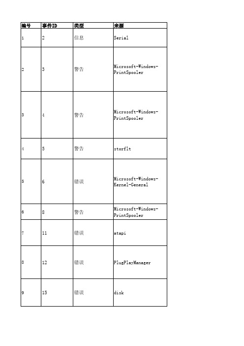
终端服务器收到大量没有完成的连接。系统可能受到攻击。
尝试读取本地主机文件时出错。
在没有配置的 DNS 服务器响应之后,名称 的名称解析超时。 终端服务启动失败。相关的状态代码为 不能在安全模式中启动 这项服务 。 用户 WIN-R9YSAKVADL8\Administrator 为这台计算机上一次意 外的关机提供的原因是: 其他(没有计划的) 原因代码: 0xa000000 问题 ID: 错误检查字符串: 注释:
错误
Tcpip
Microsoft-WindowsServicing Microsoft-WindowsServicing NtServicePack
EventLog
EventLog EventLog EventLog
EventLog
LsaSrv
Service Control Manager Service Control Manager Service Control Manager Service Control Manager
76
10149
警告
Microsoft-WindowsWinRM
77
10155
错误
Microsoft-WindowsWinRM
78
15005
79
15007
错误 信息
Microsoft-WindowsHttpEvent
HTTP
80
15016
81
15300
82
36874
36888 83
84
60054
85
FortiMonitor 端到端数字体验监控说明书

DATA SHEET | FortiMonitor2CORE COMPONENTSDigital Experience MonitoringFortiMonitor consolidates monitoring data into a single SaaS-based platform which collects telemetry across complex, hybrid infrastructures. FortiMonitor visualizes the information in a unified capacity, enabling seamless correlation. The solution:§Centralizes monitoring of the end user, network, andinfrastructure that hosts your applications to lower costs, increase efficiency, and optimize resources §Performs synthetic testing from multiple vantage points to monitor application uptime, user experience, and performance §Improves customer and end-user experience by proactively identifying service degradation §Correlates network and application performance data to quickly pinpoint root cause of issues §Leverages endpoint performance data, such as CPU,memory, disk, and network metrics, along with network and application performance. This facilitates troubleshooting with insights into what the user is experiencingComprehensive Full Stack Visibility and Fortinet Fabric IntegrationFortiMonitor uniquely offers the ability to observe health and performance of all of your devices, across any network, and the infrastructure that applications utilize, whether containers, cloud, on-premises, or hybrid.§Monitors status and health of end-user devices, network, cloud, and on-prem infrastructure, public, or privately hosted applications. §Integrates with the Fortinet Security-Fabric to easily discover and gain insight into FortiGate and downstream Fortinet device health and performance metrics, including LAN, Wi-Fi, and SD-WAN. §Simulates application-specific traffic over SD-WANunderlays to accurately measure real-time user experienceand application performance over SD-WANDATA SHEET | FortiMonitorEnriched Incident and Event Management FortiMonitor enables organizations to observe, correlate, and respond to incidents from a single unified platform. Organizations can:§Enrich incidents by automating the diagnostic collection and designing remedial measures with automated runbooks, allowing teams to fully customize their incident handling experience at scale§Maximize team collaboration through native timeline and messaging communication features, accelerating response coordination§Ensure critical events trigger notification of team members instantly, through email, FortiMonitor mobile application, and SMS alerting§Eliminate fragmentation with a single source of reliable data insights AutomationFortiMonitor enables a network operator to respond to performance issues with flexible automated runbooks. These can be tuned to an organization’s best practices to accelerate operational and response tasks. Benefits of automated runbooks include:§Reduction of repetitive manual tasks and high-volume context switching§Accelerate mean time to detect (MTTD)/mean timeto response (MTTR), while improving service delivery, permitting teams to meet and exceed SLAs§Proactive optimization of processes and resolution of incidents§Swift deployment of automation for immediate use and onboardingCORE COMPONENTSFortiMonitor Live Incident Tracking3DATA SHEET | FortiMonitor4CORE COMPONENTSFeature Highlights§Comprehensive Performance Monitoring: Monitorendpoints, vendor agnostic network devices, infrastructure, applications, and cloud services with a single, SaaS-based platform. §Endpoint Digital Experience: Leverage endpoint performance data, such as CPU, memory, disk, and network metrics, along with network and applicationperformance to facilitate troubleshooting with insights into what an end user is experiencing. §Fortinet Fabric Integration: Discover and monitor FortiGate and downstream Fortinet device health and performance metrics, including LAN, Wi-Fi, and SD-WAN. §Flexible automated onboarding: Easily onboard FortiGate and connected FortiAP, FortiSwitch and FortiExtender devices. §Auto Discovery : Network-wide SNMP device discovery. Host and guest performance of VMWare , Kubernetes Helm. §Cloud Integrations: AWS, Azure,§Synthetic Transaction Monitoring (STM): Gain visibility into the availability and performance of any application using browser tracing or javascript that run from global public nodes and private networks §Incident Flow: Send and escalate alerts via mobile app, email, SMS, phone call, and third-party ticketing integrations, with advanced alert timelines §Topology Mapping: Visualize all network elements in real time to see how they connect and identify performance issues. §Network Configuration Management (NCM): Get centralized network configuration management and templates for seamless configuration updates. § Multi-tenancy: Manage client devices while providing role-based access control (RBAC) for insights into digital experience performance monitoring. §Dashboards and reporting: Save time with out-of-the-box and customizable dashboards, reports and public status pages for real-time and historical reporting. §Alert Integrations: Integrate with JIRA, Slack, Microsoft TeamsDATA SHEET | FortiMonitor COLLECTOR APPLIANCEDeploy Key Component 100F ApplianceFortiMonitor is a cloud-native, vendor-neutral, SaaS-based monitoring platform offering key strengths in digital experience monitoring, FortiOS and Fabric integration, and importantly, network device detection and monitoring. Furthermore, with offerings such as Incident Management, NetFlow and NCM, FortiMonitor quickly becomes a platform of tool consolidation and workflow centralisation. Importantly, one of the key components in the FortiMonitor deployment strategy is the FortiMonitor OnSight Collector appliance. The FortiMonitor Onsight appliance is perhaps the most ubiquitous of facilities in the FortiMonitor toolbox, offering a plethora of network level insights, including FortiOS Insights, all in a single appliance.The FortiMonitor 100F comes fully prepared with everything you need to quickly get up and running, but with the added benefit of a “plug and play” deployment strategy. This unit brings significant compute capacity right to the edge—to the end-user environment, network, and remote branch location. Out of the box, the 100F is designed to support maximum volumes of metric collection as follows:§150,000 SNMP metrics§2500 VMWare instances (hosts, clusters, VMs, datastores)§4500 synthetic network checks (ping, HTTP, HTTPS)§100 browser-based synthetic checksHowever, if you wish to deploy FortiMonitor Onsight appliance where a requirement exists for values beyond these specifications, FortiMonitor has this prospect taken care of. Using the feature of “OnSight Groups” (a FortiMonitor configuration option) it is entirely possible to harness the abilities of multiple Onsight units operating in HA / LB tandem, depending on your configuration.Upon deployment, the initial setup is performed locally on the device itself, and once that’s complete, all administrative and management functions are streamlined through the web-based FortiMonitor control panel. This approach gives the FortiMonitor 100F a familiar look and feel. Enabling monitoringat scale has never been so easy.5DATA SHEET | FortiMonitor6THE FORTINET SECURITY FABRICFortiMonitor integration with the Fortinet Security Fabric enables organizations to import all eligible Fortinet devices into the FortiMonitor platform. This enables digital experience and network performance monitoring at scale. TheFortiMonitor platform brings enriched alerting and an incident management toolset to managed devices for proactive monitoring and generating of alerts in response to error conditions.Fortinet Services24/7 FortiCare Service24x7 FortiCare technical support is delivered through ourGlobal Technical Assistance Centers. Each geographical region has a Center of Expertise that is supplemented by regional support centers. This enables us to provide regional and local language support. Foundational FortiCare device-level support includes:§Global toll-free numbers that are available 24x7 §Web chat for quick answers§ A support portal for ticket creation or to manage assets and life cycles §Access to software updates and a standard next-business-day RMA service for the device FortiCare Best Practice Services for FortiMonitorThe FortiCare Best Practice Service (BPS) provides technical advice to help organizations make the most of their Fortinet investment. FortiCare BPS is an annual subscription-based service. Once a ticket is created through the FortiCareSupport Portal, the BPS ticket is rerouted to a product-specific technical expert. Response for these consultations are handled as per a standard P3 ticket.Security FabricThe industry’s highest-performing cybersecurity platform, powered by FortiOS, with a rich ecosystem designed to span the extended digital attack surface, delivering fully automated, self-healing network security.§Broad . Coordinated detection and enforcement across the entire digital attack surface and lifecycle with converged networking and security across edges, clouds, endpoints and users §Integrated . Integrated and unified security, operation, and performance across different technologies, location, deployment options, and the richest Ecosystem §Automated . Context aware, self-healing network, and security posture leveraging cloud-scale and advanced AI to automatically deliver near-real-time, user-to-application coordinated protection across the Fabric The Fabric empowers organizations of any size to secure and simplify their hybrid infrastructure on the journey to digitalinnovation.DATA SHEET | FortiMonitorFMR-DAT-R05-20230206Copyright © 2023 Fortinet, Inc. All rights reserved. Fortinet , FortiGate , FortiCare and FortiGuard , and certain other marks are registered trademarks of Fortinet, Inc., and other Fortinet names herein may also be registered and/or common law trademarks of Fortinet. All other product or company names may be trademarks of their respective owners. Performance and other metrics contained herein were attained in internal lab tests under ideal conditions, and actual performance and other results may vary. Network variables, different network environments and other conditions may affect performance results. Nothing herein represents any binding commitment by Fortinet, and Fortinet disclaims all warranties, whether express or implied, except to the extent Fortinet enters a binding written contract, signed by Fortinet’s General Counsel, with a purchaser that expressly warrants that the identified product will perform according to certain expressly-identified performance metrics and, in such event, only the specific performance metrics expressly identified in such binding written contract shall be binding on Fortinet. For absolute clarity, any such warranty will be limited to performance in the same ideal conditions as in Fortinet’s internal lab tests. Fortinet disclaims in full any covenants, representations, and guarantees pursuant hereto, whether express or implied. Fortinet reserves the right to change, modify, transfer, or otherwise revise this publication without notice, and the most current version of the publication shall be applicable.Fortinet is committed to driving progress and sustainability for all through cybersecurity, with respect for human rights and ethical business practices, making possible a digital world you can always trust. You represent and warrant to Fortinet that you will not use Fortinet’s products and services to engage in, or support in any way, violations or abuses of human rights, including those involving illegal censorship, surveillance, detention, or excessive use of force. Users of Fortinet products are required to comply with the Fortinet EULA (https:///content/dam/fortinet/assets/legal/EULA.pdf ) and report any suspected violations of the EULA via the procedures outlined in the Fortinet Whistleblower Policy (https:///domain/media/en/gui/19775/Whistleblower_Policy.pdf ). ORDER INFORMATIONDevice/Server Subscriptions25-pack FC2-10-MNCLD-436-01-DD FC2-10-MNCLD-437-01-DD 500-pack FC3-10-MNCLD-436-01-DD FC3-10-MNCLD-437-01-DD 2000-pack FC4-10-MNCLD-436-01-DD FC4-10-MNCLD-437-01-DD 10 000-packFC5-10-MNCLD-436-01-DD FC5-10-MNCLD-437-01-DD Container Subscriptions25-pack FC2-10-MNCLD-439-01-DD FC2-10-MNCLD-440-01-DD 500-pack FC3-10-MNCLD-439-01-DD FC3-10-MNCLD-440-01-DD 2000-pack FC4-10-MNCLD-439-01-DD FC4-10-MNCLD-440-01-DD 10 000-packFC5-10-MNCLD-439-01-DD FC5-10-MNCLD-440-01-DD FortiGate Subscriptions25-pack FC2-10-MNCLD-456-01-DD FC2-10-MNCLD-457-01-DD 500-pack FC3-10-MNCLD-456-01-DD FC3-10-MNCLD-460-01-DD 2000-pack FC4-10-MNCLD-456-01-DD FC4-10-MNCLD-457-01-DD 10 000-packFC5-10-MNCLD-456-01-DD FC5-10-MNCLD-457-01-DD LAN Edge Device Subscriptions25-pack FC2-10-MNCLD-459-01-DD FC2-10-MNCLD-460-01-DD 500-pack FC3-10-MNCLD-459-01-DD FC3-10-MNCLD-460-01-DD 2000-pack FC4-10-MNCLD-459-01-DD FC4-10-MNCLD-460-01-DD 10 000-packFC5-10-MNCLD-459-01-DDFC5-10-MNCLD-460-01-DDDEM Synthetics Subscriptions25-pack FC2-10-MNCLD-441-01-DD 500-pack FC3-10-MNCLD-441-01-DD 2000-pack FC4-10-MNCLD-441-01-DD 10 000-packFC5-10-MNCLD-441-01-DDDigital Experience Monitoring (DEM) subscriptions for advanced synthetics monitoring are also available independently from endpoint servers and containers.Separate SKUs are provided for devices/servers, containers, FortiGate, and LAN Edge devices.FortiCare Best Practices (BPS) Onboarding Service< 250 EndpointsFC1-10-MNBPS-310-02-DD 250 - 999 Endpoints FC2-10-MNBPS-310-02-DD 1000 - 4999 Endpoints FC3-10-MNBPS-310-02-DD >= 5000 EndpointsFC5-10-MNBPS-310-02-DDFortiMonitor 100FFMR-100FThe FortiMonitor 100F is the appliance-based OnSight Collector, allowing a single hardware appliance for STM, SNMP Trap/Get and FortiMonitor Agent connectivity.Additional onboarding services are available as subscriptions providing onboarding consultation services.FortiMonitor Collector appliance is available now.Other FortiMonitor SKUs are orderable for Basic Nodes: Basic instances are also available for simple uptime/availabilitymonitoring of endpoints, devices, servers, and websites. This instance type does not include advanced performance metrics.ALSO AVAILABLE。
信息安全科技英语课后汉译英英文部分
1) Initially the hacker is a skilled writing and debugging of computer programming skills, and the use of these techniques to obtain illegal or unauthorized network or file access, invasion of Intranet for the people. With a variety of powerful hacking tools are widely spread, the computer technology to understand very few people can also implement of hacker attack behavior, so the network system hacking attacks significantly increased the likelihood of.2) Active attack can cause network system status and service change. Active attacks include attempting to stop or break protection mechanism, introduce malicious code, theft or tamper with the information. Active attack may cause data disclosure and dissemination, or cause a denial of service and data tampering, including most of the unauthorized user attempts to abnormal means and the normal means of access to the remote host.3) General complete attack process is to hide themselves, hiding yourself after the attack detection, detection of target machines with various properties, and have been attack condition; then take corresponding attack methods were destroyed, achieve his goal after the attacker will remove their behavior in the target system log.4) General complete attack process is to hide themselves, hiding yourself after the attack detection, detection of target machines with various properties, and have been attack condition; then take corresponding attack methods were destroyed, achieve his goal after the attacker will remove their behavior in the target system log.5) Denial of service attack, is through illegal monopoly target system services, ultimately trying to prevent legitimate users target to provide network services. Denial of service attack is the most common attack through the resulting in a large number of flows to the victim network packet, the network consume all available bandwidth.6) Modern cryptography is one of the basic principles are: all secrets are present and the key. The implication is that, in the design of encryption system, always assume the cipher algorithm is disclosed, really need to keep it secret. This is because the cipher algorithm is easier to reveal the relative key.7) Symmetric cipher password required to achieve through the security code channel by sender to receiver. The password system 's advantages are: high safety, fast encryption speed. The shortcoming is: with the expansion of network scale, key management becomes a difficulty;cannot solve the message confirmation problems; lack of automatic detection of key leakage ability.8) Cryptographic protocol has the following characteristics: agreement from first to last is a sequential process, every step must be performed, in the former step without prior to implementation, the following steps are not possible; protocol requires at least two participants; the protocol must be able to complete a certain task; protocol must meet certain security requirements.9) As a result of cryptography for communication to provide strong security, the attacker has turned to loopholes in the system. Loopholes in the system is a software system, network protocols such as in the preparation of safe flaw, the attacker can use these flaw carries on the attack to the system. For this type of attack, there are a variety of different coping techniques, and cryptography has to a certain extent, can play a role in.10) Public key cryptography is also known as asymmetric key cipher. Using public key cryptography each user separately has two key: encryption keys and decryption key, both of them are not the same, and the encryption key decryption keys on the computer is not feasible. Each user's encryption key are open (and hence, also known as the public key encryption key ).11) If the Internet and are accessed through the firewall, then the firewall, can record various visits, and provides information about network utilization value statistics. If a firewall in suspicious activity occurred when the alarm, it also provides the firewall and network are affected by the trial or attack details.12) The present firewall values are provided on external network user attack protection, from the internal network users to attack to rely on internal network host system by. The firewall can't forbid apostates or company spy sensitive data is copied to a floppy disk or PCMCIA card, and took them out of the company.13) The firewall can prevent data driven attack. If the user is graspinga program on the local operation, the program is likely to include a malicious code. With the Java, JavaScript and ActiveX controls a large number of use, this problem becomes more and more sharp.14) Packet filtering technology, as the name suggests is in proper position on the network data packets carried out selectively by, selectionbasis, namely system within a set of filter rules ( often referred to as the access control list -- Access Control List ), only to meet the data packet filtering rules to be forwarded to the corresponding network interface, the remaining data package is removed from the data stream.15) D ifferent types of firewalls are able to provide identification and authentication functions, the network user is usually considered credible, outside the network of users in access network resources are usually certified. Password authentication from the technical point of view, is not a very strong authentication, password based attack is a common attack, firewall, other filter access authentication method: one time password, the password based on time and challenge response scheme.16) I ntrusion detection is the rational supplement of the firewall, the help system against network attack, expanded the safe management of system administrator ( including safe audit, surveillance, attack recognition and response), improve the integrity of the information security foundation structure. It is thought to be behind a firewall second security gate, without affecting the performance of network condition on the network can be detected, thereby providing for internal attacks, external attack and wrong operation real time protection.17) I ntrusion detection, Intrusion Detection, is on the intrusion behavior found, through the computer network or computer systems in a number of key point of collecting and analyzing the information, found from the network or system of violating security policy behavior and signs of attack.18) The IDS system 's two major functions: real-time detection and safety audit. Real time detection of real-time monitoring, analysis of the network of all data packets, and real-time processing of the captured data packets; security audit based on IDS system records the network time for statistical analysis, found that the abnormal phenomenon, that the security state of the system, find out the evidence required.19) Most of the traditional intrusion detection system ( IDS ) take based on network or host based approach to identify and avoid attack. In either case, the product will be looking for" the attack flag", i.e. a malicious or questionable intent to attack mode. When the IDS in the network to find these patterns, it is based on the network. And when the IDS in a record file for the attack when the mark, which is based on host.20) Based on sentence due to IDS (HIDS) using data is the main source of audit log, system log, application logs and network connection data, these data have the success / failure event information, so it can becompared based on network IDS more accurately determine whether the attack was successful.21) IEFE based on IP draft definition VPN: using IP mechanism simulation of a private network, through private tunnel in public data network technology in simulation of a point-to-point line technology. Virtual private network is to rely on the ISP ( Internet service provider ) and other network service provider, in a public network for data communication network technology.22) VPN also made up of 3 components, different VPN connection using a tunnel as a transmission channel, the tunnel is built in a public network or a private network on the basis of, such as Internet or Intranet, users no longer need to have special long-distance data line.23) Security is one of the important features of the special network. Because VPN directly built on the public network, the realization of a simple, convenient and flexible, but at the same time, the security problem is more prominent. The enterprise must make sure that the VPN transmitted data are not the attacker snoops and tamper with, and to prevent the illegal user from cyber source or private information access. ExtranetVPN enterprise network expansion to partners and customers, for the safety of a higher demand.24) VPN requires the enterprise of its network management functions from the local area network seamlessly extends to the public network, or even customers and partners, although can be some minor network management task to the service provider to complete, enterprises still need to accomplish many tasks of network management, so, the VPN system should support the user management. The VPN management including safety management, equipment management, configuration management, access control list management, QoS management, to achieve reduced network risk, with high scalability, economy, high reliability target.25) VPN through the public network to establish links, so it is necessary to use encryption to prevent eavesdropping, protection of corporate data security. Common encryption algorithm including DES,3DES etc.. DES key length of 56 bits, easily deciphered, 3DES uses three encryption of increased safety.26) Computer virus epidemic began in November 2, 1988. The United States Cornell University 23 years of graduate Lott Maurice produced a worm, and putting it on the Internet to the United States, resulting in the computer network of more than 6000 computers were infected, manynetworked computers to shutdown, the direct economic losses of $.27) A computer virus is a small program, able to replicate themselves, will own the virus code attached to other procedures, through the execution of other programs, for the propagation of the virus program, have a certain latency, when conditions are ripe, they are all sorts of sabotage, the effects of computer use.28) Now popular virus is composed of that deliberately prepared, most viruses can be found on the author information and the origin of information, through the analysis of large volumes of data statistics, virus author main condition and objective is: some talented programmer to show and prove their ability, due to the dissatisfaction of boss, for the curious, in retaliation, in order to congratulate and courtship, in order to get control of the password, to prevent software to get paid for the trap.29) Hybrid virus is not a simple file type virus and boot viruses simply added together, there is a conversion process, which is the most key. Generally take the gimmick: files for viruses when performing the virus writes the boot area, it is easy to understand.30) The computer virus is an objective existence, objective existence has its characteristics, computer virus is no exception. Essentially, a computer virus is a program code, although it may well hidden, but also left many traces. Through to these traces of discrimination, we can find the computer virus in the presence of.。
3GPP TS 36.331 V13.2.0 (2016-06)
3GPP TS 36.331 V13.2.0 (2016-06)Technical Specification3rd Generation Partnership Project;Technical Specification Group Radio Access Network;Evolved Universal Terrestrial Radio Access (E-UTRA);Radio Resource Control (RRC);Protocol specification(Release 13)The present document has been developed within the 3rd Generation Partnership Project (3GPP TM) and may be further elaborated for the purposes of 3GPP. The present document has not been subject to any approval process by the 3GPP Organizational Partners and shall not be implemented.This Specification is provided for future development work within 3GPP only. The Organizational Partners accept no liability for any use of this Specification. Specifications and reports for implementation of the 3GPP TM system should be obtained via the 3GPP Organizational Partners' Publications Offices.KeywordsUMTS, radio3GPPPostal address3GPP support office address650 Route des Lucioles - Sophia AntipolisValbonne - FRANCETel.: +33 4 92 94 42 00 Fax: +33 4 93 65 47 16InternetCopyright NotificationNo part may be reproduced except as authorized by written permission.The copyright and the foregoing restriction extend to reproduction in all media.© 2016, 3GPP Organizational Partners (ARIB, ATIS, CCSA, ETSI, TSDSI, TTA, TTC).All rights reserved.UMTS™ is a Trade Mark of ETSI registered for the benefit of its members3GPP™ is a Trade Mark of ETSI registered for the benefit of its Members and of the 3GPP Organizational PartnersLTE™ is a Trade Mark of ETSI currently being registered for the benefit of its Members and of the 3GPP Organizational Partners GSM® and the GSM logo are registered and owned by the GSM AssociationBluetooth® is a Trade Mark of the Bluetooth SIG registered for the benefit of its membersContentsForeword (18)1Scope (19)2References (19)3Definitions, symbols and abbreviations (22)3.1Definitions (22)3.2Abbreviations (24)4General (27)4.1Introduction (27)4.2Architecture (28)4.2.1UE states and state transitions including inter RAT (28)4.2.2Signalling radio bearers (29)4.3Services (30)4.3.1Services provided to upper layers (30)4.3.2Services expected from lower layers (30)4.4Functions (30)5Procedures (32)5.1General (32)5.1.1Introduction (32)5.1.2General requirements (32)5.2System information (33)5.2.1Introduction (33)5.2.1.1General (33)5.2.1.2Scheduling (34)5.2.1.2a Scheduling for NB-IoT (34)5.2.1.3System information validity and notification of changes (35)5.2.1.4Indication of ETWS notification (36)5.2.1.5Indication of CMAS notification (37)5.2.1.6Notification of EAB parameters change (37)5.2.1.7Access Barring parameters change in NB-IoT (37)5.2.2System information acquisition (38)5.2.2.1General (38)5.2.2.2Initiation (38)5.2.2.3System information required by the UE (38)5.2.2.4System information acquisition by the UE (39)5.2.2.5Essential system information missing (42)5.2.2.6Actions upon reception of the MasterInformationBlock message (42)5.2.2.7Actions upon reception of the SystemInformationBlockType1 message (42)5.2.2.8Actions upon reception of SystemInformation messages (44)5.2.2.9Actions upon reception of SystemInformationBlockType2 (44)5.2.2.10Actions upon reception of SystemInformationBlockType3 (45)5.2.2.11Actions upon reception of SystemInformationBlockType4 (45)5.2.2.12Actions upon reception of SystemInformationBlockType5 (45)5.2.2.13Actions upon reception of SystemInformationBlockType6 (45)5.2.2.14Actions upon reception of SystemInformationBlockType7 (45)5.2.2.15Actions upon reception of SystemInformationBlockType8 (45)5.2.2.16Actions upon reception of SystemInformationBlockType9 (46)5.2.2.17Actions upon reception of SystemInformationBlockType10 (46)5.2.2.18Actions upon reception of SystemInformationBlockType11 (46)5.2.2.19Actions upon reception of SystemInformationBlockType12 (47)5.2.2.20Actions upon reception of SystemInformationBlockType13 (48)5.2.2.21Actions upon reception of SystemInformationBlockType14 (48)5.2.2.22Actions upon reception of SystemInformationBlockType15 (48)5.2.2.23Actions upon reception of SystemInformationBlockType16 (48)5.2.2.24Actions upon reception of SystemInformationBlockType17 (48)5.2.2.25Actions upon reception of SystemInformationBlockType18 (48)5.2.2.26Actions upon reception of SystemInformationBlockType19 (49)5.2.3Acquisition of an SI message (49)5.2.3a Acquisition of an SI message by BL UE or UE in CE or a NB-IoT UE (50)5.3Connection control (50)5.3.1Introduction (50)5.3.1.1RRC connection control (50)5.3.1.2Security (52)5.3.1.2a RN security (53)5.3.1.3Connected mode mobility (53)5.3.1.4Connection control in NB-IoT (54)5.3.2Paging (55)5.3.2.1General (55)5.3.2.2Initiation (55)5.3.2.3Reception of the Paging message by the UE (55)5.3.3RRC connection establishment (56)5.3.3.1General (56)5.3.3.1a Conditions for establishing RRC Connection for sidelink communication/ discovery (58)5.3.3.2Initiation (59)5.3.3.3Actions related to transmission of RRCConnectionRequest message (63)5.3.3.3a Actions related to transmission of RRCConnectionResumeRequest message (64)5.3.3.4Reception of the RRCConnectionSetup by the UE (64)5.3.3.4a Reception of the RRCConnectionResume by the UE (66)5.3.3.5Cell re-selection while T300, T302, T303, T305, T306, or T308 is running (68)5.3.3.6T300 expiry (68)5.3.3.7T302, T303, T305, T306, or T308 expiry or stop (69)5.3.3.8Reception of the RRCConnectionReject by the UE (70)5.3.3.9Abortion of RRC connection establishment (71)5.3.3.10Handling of SSAC related parameters (71)5.3.3.11Access barring check (72)5.3.3.12EAB check (73)5.3.3.13Access barring check for ACDC (73)5.3.3.14Access Barring check for NB-IoT (74)5.3.4Initial security activation (75)5.3.4.1General (75)5.3.4.2Initiation (76)5.3.4.3Reception of the SecurityModeCommand by the UE (76)5.3.5RRC connection reconfiguration (77)5.3.5.1General (77)5.3.5.2Initiation (77)5.3.5.3Reception of an RRCConnectionReconfiguration not including the mobilityControlInfo by theUE (77)5.3.5.4Reception of an RRCConnectionReconfiguration including the mobilityControlInfo by the UE(handover) (79)5.3.5.5Reconfiguration failure (83)5.3.5.6T304 expiry (handover failure) (83)5.3.5.7Void (84)5.3.5.7a T307 expiry (SCG change failure) (84)5.3.5.8Radio Configuration involving full configuration option (84)5.3.6Counter check (86)5.3.6.1General (86)5.3.6.2Initiation (86)5.3.6.3Reception of the CounterCheck message by the UE (86)5.3.7RRC connection re-establishment (87)5.3.7.1General (87)5.3.7.2Initiation (87)5.3.7.3Actions following cell selection while T311 is running (88)5.3.7.4Actions related to transmission of RRCConnectionReestablishmentRequest message (89)5.3.7.5Reception of the RRCConnectionReestablishment by the UE (89)5.3.7.6T311 expiry (91)5.3.7.7T301 expiry or selected cell no longer suitable (91)5.3.7.8Reception of RRCConnectionReestablishmentReject by the UE (91)5.3.8RRC connection release (92)5.3.8.1General (92)5.3.8.2Initiation (92)5.3.8.3Reception of the RRCConnectionRelease by the UE (92)5.3.8.4T320 expiry (93)5.3.9RRC connection release requested by upper layers (93)5.3.9.1General (93)5.3.9.2Initiation (93)5.3.10Radio resource configuration (93)5.3.10.0General (93)5.3.10.1SRB addition/ modification (94)5.3.10.2DRB release (95)5.3.10.3DRB addition/ modification (95)5.3.10.3a1DC specific DRB addition or reconfiguration (96)5.3.10.3a2LWA specific DRB addition or reconfiguration (98)5.3.10.3a3LWIP specific DRB addition or reconfiguration (98)5.3.10.3a SCell release (99)5.3.10.3b SCell addition/ modification (99)5.3.10.3c PSCell addition or modification (99)5.3.10.4MAC main reconfiguration (99)5.3.10.5Semi-persistent scheduling reconfiguration (100)5.3.10.6Physical channel reconfiguration (100)5.3.10.7Radio Link Failure Timers and Constants reconfiguration (101)5.3.10.8Time domain measurement resource restriction for serving cell (101)5.3.10.9Other configuration (102)5.3.10.10SCG reconfiguration (103)5.3.10.11SCG dedicated resource configuration (104)5.3.10.12Reconfiguration SCG or split DRB by drb-ToAddModList (105)5.3.10.13Neighbour cell information reconfiguration (105)5.3.10.14Void (105)5.3.10.15Sidelink dedicated configuration (105)5.3.10.16T370 expiry (106)5.3.11Radio link failure related actions (107)5.3.11.1Detection of physical layer problems in RRC_CONNECTED (107)5.3.11.2Recovery of physical layer problems (107)5.3.11.3Detection of radio link failure (107)5.3.12UE actions upon leaving RRC_CONNECTED (109)5.3.13UE actions upon PUCCH/ SRS release request (110)5.3.14Proximity indication (110)5.3.14.1General (110)5.3.14.2Initiation (111)5.3.14.3Actions related to transmission of ProximityIndication message (111)5.3.15Void (111)5.4Inter-RAT mobility (111)5.4.1Introduction (111)5.4.2Handover to E-UTRA (112)5.4.2.1General (112)5.4.2.2Initiation (112)5.4.2.3Reception of the RRCConnectionReconfiguration by the UE (112)5.4.2.4Reconfiguration failure (114)5.4.2.5T304 expiry (handover to E-UTRA failure) (114)5.4.3Mobility from E-UTRA (114)5.4.3.1General (114)5.4.3.2Initiation (115)5.4.3.3Reception of the MobilityFromEUTRACommand by the UE (115)5.4.3.4Successful completion of the mobility from E-UTRA (116)5.4.3.5Mobility from E-UTRA failure (117)5.4.4Handover from E-UTRA preparation request (CDMA2000) (117)5.4.4.1General (117)5.4.4.2Initiation (118)5.4.4.3Reception of the HandoverFromEUTRAPreparationRequest by the UE (118)5.4.5UL handover preparation transfer (CDMA2000) (118)5.4.5.1General (118)5.4.5.2Initiation (118)5.4.5.3Actions related to transmission of the ULHandoverPreparationTransfer message (119)5.4.5.4Failure to deliver the ULHandoverPreparationTransfer message (119)5.4.6Inter-RAT cell change order to E-UTRAN (119)5.4.6.1General (119)5.4.6.2Initiation (119)5.4.6.3UE fails to complete an inter-RAT cell change order (119)5.5Measurements (120)5.5.1Introduction (120)5.5.2Measurement configuration (121)5.5.2.1General (121)5.5.2.2Measurement identity removal (122)5.5.2.2a Measurement identity autonomous removal (122)5.5.2.3Measurement identity addition/ modification (123)5.5.2.4Measurement object removal (124)5.5.2.5Measurement object addition/ modification (124)5.5.2.6Reporting configuration removal (126)5.5.2.7Reporting configuration addition/ modification (127)5.5.2.8Quantity configuration (127)5.5.2.9Measurement gap configuration (127)5.5.2.10Discovery signals measurement timing configuration (128)5.5.2.11RSSI measurement timing configuration (128)5.5.3Performing measurements (128)5.5.3.1General (128)5.5.3.2Layer 3 filtering (131)5.5.4Measurement report triggering (131)5.5.4.1General (131)5.5.4.2Event A1 (Serving becomes better than threshold) (135)5.5.4.3Event A2 (Serving becomes worse than threshold) (136)5.5.4.4Event A3 (Neighbour becomes offset better than PCell/ PSCell) (136)5.5.4.5Event A4 (Neighbour becomes better than threshold) (137)5.5.4.6Event A5 (PCell/ PSCell becomes worse than threshold1 and neighbour becomes better thanthreshold2) (138)5.5.4.6a Event A6 (Neighbour becomes offset better than SCell) (139)5.5.4.7Event B1 (Inter RAT neighbour becomes better than threshold) (139)5.5.4.8Event B2 (PCell becomes worse than threshold1 and inter RAT neighbour becomes better thanthreshold2) (140)5.5.4.9Event C1 (CSI-RS resource becomes better than threshold) (141)5.5.4.10Event C2 (CSI-RS resource becomes offset better than reference CSI-RS resource) (141)5.5.4.11Event W1 (WLAN becomes better than a threshold) (142)5.5.4.12Event W2 (All WLAN inside WLAN mobility set becomes worse than threshold1 and a WLANoutside WLAN mobility set becomes better than threshold2) (142)5.5.4.13Event W3 (All WLAN inside WLAN mobility set becomes worse than a threshold) (143)5.5.5Measurement reporting (144)5.5.6Measurement related actions (148)5.5.6.1Actions upon handover and re-establishment (148)5.5.6.2Speed dependant scaling of measurement related parameters (149)5.5.7Inter-frequency RSTD measurement indication (149)5.5.7.1General (149)5.5.7.2Initiation (150)5.5.7.3Actions related to transmission of InterFreqRSTDMeasurementIndication message (150)5.6Other (150)5.6.0General (150)5.6.1DL information transfer (151)5.6.1.1General (151)5.6.1.2Initiation (151)5.6.1.3Reception of the DLInformationTransfer by the UE (151)5.6.2UL information transfer (151)5.6.2.1General (151)5.6.2.2Initiation (151)5.6.2.3Actions related to transmission of ULInformationTransfer message (152)5.6.2.4Failure to deliver ULInformationTransfer message (152)5.6.3UE capability transfer (152)5.6.3.1General (152)5.6.3.2Initiation (153)5.6.3.3Reception of the UECapabilityEnquiry by the UE (153)5.6.4CSFB to 1x Parameter transfer (157)5.6.4.1General (157)5.6.4.2Initiation (157)5.6.4.3Actions related to transmission of CSFBParametersRequestCDMA2000 message (157)5.6.4.4Reception of the CSFBParametersResponseCDMA2000 message (157)5.6.5UE Information (158)5.6.5.1General (158)5.6.5.2Initiation (158)5.6.5.3Reception of the UEInformationRequest message (158)5.6.6 Logged Measurement Configuration (159)5.6.6.1General (159)5.6.6.2Initiation (160)5.6.6.3Reception of the LoggedMeasurementConfiguration by the UE (160)5.6.6.4T330 expiry (160)5.6.7 Release of Logged Measurement Configuration (160)5.6.7.1General (160)5.6.7.2Initiation (160)5.6.8 Measurements logging (161)5.6.8.1General (161)5.6.8.2Initiation (161)5.6.9In-device coexistence indication (163)5.6.9.1General (163)5.6.9.2Initiation (164)5.6.9.3Actions related to transmission of InDeviceCoexIndication message (164)5.6.10UE Assistance Information (165)5.6.10.1General (165)5.6.10.2Initiation (166)5.6.10.3Actions related to transmission of UEAssistanceInformation message (166)5.6.11 Mobility history information (166)5.6.11.1General (166)5.6.11.2Initiation (166)5.6.12RAN-assisted WLAN interworking (167)5.6.12.1General (167)5.6.12.2Dedicated WLAN offload configuration (167)5.6.12.3WLAN offload RAN evaluation (167)5.6.12.4T350 expiry or stop (167)5.6.12.5Cell selection/ re-selection while T350 is running (168)5.6.13SCG failure information (168)5.6.13.1General (168)5.6.13.2Initiation (168)5.6.13.3Actions related to transmission of SCGFailureInformation message (168)5.6.14LTE-WLAN Aggregation (169)5.6.14.1Introduction (169)5.6.14.2Reception of LWA configuration (169)5.6.14.3Release of LWA configuration (170)5.6.15WLAN connection management (170)5.6.15.1Introduction (170)5.6.15.2WLAN connection status reporting (170)5.6.15.2.1General (170)5.6.15.2.2Initiation (171)5.6.15.2.3Actions related to transmission of WLANConnectionStatusReport message (171)5.6.15.3T351 Expiry (WLAN connection attempt timeout) (171)5.6.15.4WLAN status monitoring (171)5.6.16RAN controlled LTE-WLAN interworking (172)5.6.16.1General (172)5.6.16.2WLAN traffic steering command (172)5.6.17LTE-WLAN aggregation with IPsec tunnel (173)5.6.17.1General (173)5.7Generic error handling (174)5.7.1General (174)5.7.2ASN.1 violation or encoding error (174)5.7.3Field set to a not comprehended value (174)5.7.4Mandatory field missing (174)5.7.5Not comprehended field (176)5.8MBMS (176)5.8.1Introduction (176)5.8.1.1General (176)5.8.1.2Scheduling (176)5.8.1.3MCCH information validity and notification of changes (176)5.8.2MCCH information acquisition (178)5.8.2.1General (178)5.8.2.2Initiation (178)5.8.2.3MCCH information acquisition by the UE (178)5.8.2.4Actions upon reception of the MBSFNAreaConfiguration message (178)5.8.2.5Actions upon reception of the MBMSCountingRequest message (179)5.8.3MBMS PTM radio bearer configuration (179)5.8.3.1General (179)5.8.3.2Initiation (179)5.8.3.3MRB establishment (179)5.8.3.4MRB release (179)5.8.4MBMS Counting Procedure (179)5.8.4.1General (179)5.8.4.2Initiation (180)5.8.4.3Reception of the MBMSCountingRequest message by the UE (180)5.8.5MBMS interest indication (181)5.8.5.1General (181)5.8.5.2Initiation (181)5.8.5.3Determine MBMS frequencies of interest (182)5.8.5.4Actions related to transmission of MBMSInterestIndication message (183)5.8a SC-PTM (183)5.8a.1Introduction (183)5.8a.1.1General (183)5.8a.1.2SC-MCCH scheduling (183)5.8a.1.3SC-MCCH information validity and notification of changes (183)5.8a.1.4Procedures (184)5.8a.2SC-MCCH information acquisition (184)5.8a.2.1General (184)5.8a.2.2Initiation (184)5.8a.2.3SC-MCCH information acquisition by the UE (184)5.8a.2.4Actions upon reception of the SCPTMConfiguration message (185)5.8a.3SC-PTM radio bearer configuration (185)5.8a.3.1General (185)5.8a.3.2Initiation (185)5.8a.3.3SC-MRB establishment (185)5.8a.3.4SC-MRB release (185)5.9RN procedures (186)5.9.1RN reconfiguration (186)5.9.1.1General (186)5.9.1.2Initiation (186)5.9.1.3Reception of the RNReconfiguration by the RN (186)5.10Sidelink (186)5.10.1Introduction (186)5.10.1a Conditions for sidelink communication operation (187)5.10.2Sidelink UE information (188)5.10.2.1General (188)5.10.2.2Initiation (189)5.10.2.3Actions related to transmission of SidelinkUEInformation message (193)5.10.3Sidelink communication monitoring (195)5.10.6Sidelink discovery announcement (198)5.10.6a Sidelink discovery announcement pool selection (201)5.10.6b Sidelink discovery announcement reference carrier selection (201)5.10.7Sidelink synchronisation information transmission (202)5.10.7.1General (202)5.10.7.2Initiation (203)5.10.7.3Transmission of SLSS (204)5.10.7.4Transmission of MasterInformationBlock-SL message (205)5.10.7.5Void (206)5.10.8Sidelink synchronisation reference (206)5.10.8.1General (206)5.10.8.2Selection and reselection of synchronisation reference UE (SyncRef UE) (206)5.10.9Sidelink common control information (207)5.10.9.1General (207)5.10.9.2Actions related to reception of MasterInformationBlock-SL message (207)5.10.10Sidelink relay UE operation (207)5.10.10.1General (207)5.10.10.2AS-conditions for relay related sidelink communication transmission by sidelink relay UE (207)5.10.10.3AS-conditions for relay PS related sidelink discovery transmission by sidelink relay UE (208)5.10.10.4Sidelink relay UE threshold conditions (208)5.10.11Sidelink remote UE operation (208)5.10.11.1General (208)5.10.11.2AS-conditions for relay related sidelink communication transmission by sidelink remote UE (208)5.10.11.3AS-conditions for relay PS related sidelink discovery transmission by sidelink remote UE (209)5.10.11.4Selection and reselection of sidelink relay UE (209)5.10.11.5Sidelink remote UE threshold conditions (210)6Protocol data units, formats and parameters (tabular & ASN.1) (210)6.1General (210)6.2RRC messages (212)6.2.1General message structure (212)–EUTRA-RRC-Definitions (212)–BCCH-BCH-Message (212)–BCCH-DL-SCH-Message (212)–BCCH-DL-SCH-Message-BR (213)–MCCH-Message (213)–PCCH-Message (213)–DL-CCCH-Message (214)–DL-DCCH-Message (214)–UL-CCCH-Message (214)–UL-DCCH-Message (215)–SC-MCCH-Message (215)6.2.2Message definitions (216)–CounterCheck (216)–CounterCheckResponse (217)–CSFBParametersRequestCDMA2000 (217)–CSFBParametersResponseCDMA2000 (218)–DLInformationTransfer (218)–HandoverFromEUTRAPreparationRequest (CDMA2000) (219)–InDeviceCoexIndication (220)–InterFreqRSTDMeasurementIndication (222)–LoggedMeasurementConfiguration (223)–MasterInformationBlock (225)–MBMSCountingRequest (226)–MBMSCountingResponse (226)–MBMSInterestIndication (227)–MBSFNAreaConfiguration (228)–MeasurementReport (228)–MobilityFromEUTRACommand (229)–Paging (232)–ProximityIndication (233)–RNReconfiguration (234)–RNReconfigurationComplete (234)–RRCConnectionReconfiguration (235)–RRCConnectionReconfigurationComplete (240)–RRCConnectionReestablishment (241)–RRCConnectionReestablishmentComplete (241)–RRCConnectionReestablishmentReject (242)–RRCConnectionReestablishmentRequest (243)–RRCConnectionReject (243)–RRCConnectionRelease (244)–RRCConnectionResume (248)–RRCConnectionResumeComplete (249)–RRCConnectionResumeRequest (250)–RRCConnectionRequest (250)–RRCConnectionSetup (251)–RRCConnectionSetupComplete (252)–SCGFailureInformation (253)–SCPTMConfiguration (254)–SecurityModeCommand (255)–SecurityModeComplete (255)–SecurityModeFailure (256)–SidelinkUEInformation (256)–SystemInformation (258)–SystemInformationBlockType1 (259)–UEAssistanceInformation (264)–UECapabilityEnquiry (265)–UECapabilityInformation (266)–UEInformationRequest (267)–UEInformationResponse (267)–ULHandoverPreparationTransfer (CDMA2000) (273)–ULInformationTransfer (274)–WLANConnectionStatusReport (274)6.3RRC information elements (275)6.3.1System information blocks (275)–SystemInformationBlockType2 (275)–SystemInformationBlockType3 (279)–SystemInformationBlockType4 (282)–SystemInformationBlockType5 (283)–SystemInformationBlockType6 (287)–SystemInformationBlockType7 (289)–SystemInformationBlockType8 (290)–SystemInformationBlockType9 (295)–SystemInformationBlockType10 (295)–SystemInformationBlockType11 (296)–SystemInformationBlockType12 (297)–SystemInformationBlockType13 (297)–SystemInformationBlockType14 (298)–SystemInformationBlockType15 (298)–SystemInformationBlockType16 (299)–SystemInformationBlockType17 (300)–SystemInformationBlockType18 (301)–SystemInformationBlockType19 (301)–SystemInformationBlockType20 (304)6.3.2Radio resource control information elements (304)–AntennaInfo (304)–AntennaInfoUL (306)–CQI-ReportConfig (307)–CQI-ReportPeriodicProcExtId (314)–CrossCarrierSchedulingConfig (314)–CSI-IM-Config (315)–CSI-IM-ConfigId (315)–CSI-RS-Config (317)–CSI-RS-ConfigEMIMO (318)–CSI-RS-ConfigNZP (319)–CSI-RS-ConfigNZPId (320)–CSI-RS-ConfigZP (321)–CSI-RS-ConfigZPId (321)–DMRS-Config (321)–DRB-Identity (322)–EPDCCH-Config (322)–EIMTA-MainConfig (324)–LogicalChannelConfig (325)–LWA-Configuration (326)–LWIP-Configuration (326)–RCLWI-Configuration (327)–MAC-MainConfig (327)–P-C-AndCBSR (332)–PDCCH-ConfigSCell (333)–PDCP-Config (334)–PDSCH-Config (337)–PDSCH-RE-MappingQCL-ConfigId (339)–PHICH-Config (339)–PhysicalConfigDedicated (339)–P-Max (344)–PRACH-Config (344)–PresenceAntennaPort1 (346)–PUCCH-Config (347)–PUSCH-Config (351)–RACH-ConfigCommon (355)–RACH-ConfigDedicated (357)–RadioResourceConfigCommon (358)–RadioResourceConfigDedicated (362)–RLC-Config (367)–RLF-TimersAndConstants (369)–RN-SubframeConfig (370)–SchedulingRequestConfig (371)–SoundingRS-UL-Config (372)–SPS-Config (375)–TDD-Config (376)–TimeAlignmentTimer (377)–TPC-PDCCH-Config (377)–TunnelConfigLWIP (378)–UplinkPowerControl (379)–WLAN-Id-List (382)–WLAN-MobilityConfig (382)6.3.3Security control information elements (382)–NextHopChainingCount (382)–SecurityAlgorithmConfig (383)–ShortMAC-I (383)6.3.4Mobility control information elements (383)–AdditionalSpectrumEmission (383)–ARFCN-ValueCDMA2000 (383)–ARFCN-ValueEUTRA (384)–ARFCN-ValueGERAN (384)–ARFCN-ValueUTRA (384)–BandclassCDMA2000 (384)–BandIndicatorGERAN (385)–CarrierFreqCDMA2000 (385)–CarrierFreqGERAN (385)–CellIndexList (387)–CellReselectionPriority (387)–CellSelectionInfoCE (387)–CellReselectionSubPriority (388)–CSFB-RegistrationParam1XRTT (388)–CellGlobalIdEUTRA (389)–CellGlobalIdUTRA (389)–CellGlobalIdGERAN (390)–CellGlobalIdCDMA2000 (390)–CellSelectionInfoNFreq (391)–CSG-Identity (391)–FreqBandIndicator (391)–MobilityControlInfo (391)–MobilityParametersCDMA2000 (1xRTT) (393)–MobilityStateParameters (394)–MultiBandInfoList (394)–NS-PmaxList (394)–PhysCellId (395)–PhysCellIdRange (395)–PhysCellIdRangeUTRA-FDDList (395)–PhysCellIdCDMA2000 (396)–PhysCellIdGERAN (396)–PhysCellIdUTRA-FDD (396)–PhysCellIdUTRA-TDD (396)–PLMN-Identity (397)–PLMN-IdentityList3 (397)–PreRegistrationInfoHRPD (397)–Q-QualMin (398)–Q-RxLevMin (398)–Q-OffsetRange (398)–Q-OffsetRangeInterRAT (399)–ReselectionThreshold (399)–ReselectionThresholdQ (399)–SCellIndex (399)–ServCellIndex (400)–SpeedStateScaleFactors (400)–SystemInfoListGERAN (400)–SystemTimeInfoCDMA2000 (401)–TrackingAreaCode (401)–T-Reselection (402)–T-ReselectionEUTRA-CE (402)6.3.5Measurement information elements (402)–AllowedMeasBandwidth (402)–CSI-RSRP-Range (402)–Hysteresis (402)–LocationInfo (403)–MBSFN-RSRQ-Range (403)–MeasConfig (404)–MeasDS-Config (405)–MeasGapConfig (406)–MeasId (407)–MeasIdToAddModList (407)–MeasObjectCDMA2000 (408)–MeasObjectEUTRA (408)–MeasObjectGERAN (412)–MeasObjectId (412)–MeasObjectToAddModList (412)–MeasObjectUTRA (413)–ReportConfigEUTRA (422)–ReportConfigId (425)–ReportConfigInterRAT (425)–ReportConfigToAddModList (428)–ReportInterval (429)–RSRP-Range (429)–RSRQ-Range (430)–RSRQ-Type (430)–RS-SINR-Range (430)–RSSI-Range-r13 (431)–TimeToTrigger (431)–UL-DelayConfig (431)–WLAN-CarrierInfo (431)–WLAN-RSSI-Range (432)–WLAN-Status (432)6.3.6Other information elements (433)–AbsoluteTimeInfo (433)–AreaConfiguration (433)–C-RNTI (433)–DedicatedInfoCDMA2000 (434)–DedicatedInfoNAS (434)–FilterCoefficient (434)–LoggingDuration (434)–LoggingInterval (435)–MeasSubframePattern (435)–MMEC (435)–NeighCellConfig (435)–OtherConfig (436)–RAND-CDMA2000 (1xRTT) (437)–RAT-Type (437)–ResumeIdentity (437)–RRC-TransactionIdentifier (438)–S-TMSI (438)–TraceReference (438)–UE-CapabilityRAT-ContainerList (438)–UE-EUTRA-Capability (439)–UE-RadioPagingInfo (469)–UE-TimersAndConstants (469)–VisitedCellInfoList (470)–WLAN-OffloadConfig (470)6.3.7MBMS information elements (472)–MBMS-NotificationConfig (472)–MBMS-ServiceList (473)–MBSFN-AreaId (473)–MBSFN-AreaInfoList (473)–MBSFN-SubframeConfig (474)–PMCH-InfoList (475)6.3.7a SC-PTM information elements (476)–SC-MTCH-InfoList (476)–SCPTM-NeighbourCellList (478)6.3.8Sidelink information elements (478)–SL-CommConfig (478)–SL-CommResourcePool (479)–SL-CP-Len (480)–SL-DiscConfig (481)–SL-DiscResourcePool (483)–SL-DiscTxPowerInfo (485)–SL-GapConfig (485)。
计算机期刊大全
计算机期刊大全【前言】随着计算机技术的快速发展,越来越多的人开始关注计算机期刊,以获取最新的科研成果和技术进展。
本文旨在介绍全球范围内主要的计算机期刊,帮助读者了解各期刊的主题范围、影响因子、最新收录论文等信息,以提高论文发表效率和科研成果的质量。
【一、计算机科学顶级期刊】计算机领域的顶级期刊,对于任何一位计算机科学家来说,都是非常重要的。
这些期刊的文章水平高、质量优,其发表文章往往具有一定的权威性和影响力。
以下是全球最著名的计算机科学顶级期刊:1.《ACM Transactions on Computer Systems》(ACM TOCS)主题范围:该期刊关注计算机系统的设计、分析、实现和评估等方面,特别是操作系统、网络、分布式系统、数据库管理系统和存储系统等方面的最新研究成果。
影响因子:3.612发行周期:每年4期最新收录论文:Content-Based Data Placement for Efficient Query Processing on Heterogeneous Storage Systems, A Framework for Evaluating Kernel-Level Detectors, etc.2.《IEEE Transactions on Computers》(IEEE TC)主题范围:该期刊刊登计算机科学领域的创新性研究成果,重点关注计算机系统、组件和软件的设计、分析、实现和评估等方面的最新进展。
影响因子:4.804发行周期:每月1期最新收录论文:A Comprehensive View of Datacenter Network Architecture, Design, and Operations, An Efficient GPU Implementation of Imperfect Hash Tables, etc.3.《IEEE Transactions on Software Engineering》(IEEE TSE)主题范围:该期刊涉及软件工程领域的各个方面,包括软件开发、可靠性、维护、测试等方面的最新研究成果。
jstd035声学扫描
JOINT INDUSTRY STANDARDAcoustic Microscopy for Non-HermeticEncapsulatedElectronicComponents IPC/JEDEC J-STD-035APRIL1999Supersedes IPC-SM-786 Supersedes IPC-TM-650,2.6.22Notice EIA/JEDEC and IPC Standards and Publications are designed to serve thepublic interest through eliminating misunderstandings between manufacturersand purchasers,facilitating interchangeability and improvement of products,and assisting the purchaser in selecting and obtaining with minimum delaythe proper product for his particular need.Existence of such Standards andPublications shall not in any respect preclude any member or nonmember ofEIA/JEDEC or IPC from manufacturing or selling products not conformingto such Standards and Publications,nor shall the existence of such Standardsand Publications preclude their voluntary use by those other than EIA/JEDECand IPC members,whether the standard is to be used either domestically orinternationally.Recommended Standards and Publications are adopted by EIA/JEDEC andIPC without regard to whether their adoption may involve patents on articles,materials,or processes.By such action,EIA/JEDEC and IPC do not assumeany liability to any patent owner,nor do they assume any obligation whateverto parties adopting the Recommended Standard or ers are alsowholly responsible for protecting themselves against all claims of liabilities forpatent infringement.The material in this joint standard was developed by the EIA/JEDEC JC-14.1Committee on Reliability Test Methods for Packaged Devices and the IPCPlastic Chip Carrier Cracking Task Group(B-10a)The J-STD-035supersedes IPC-TM-650,Test Method2.6.22.For Technical Information Contact:Electronic Industries Alliance/ JEDEC(Joint Electron Device Engineering Council)2500Wilson Boulevard Arlington,V A22201Phone(703)907-7560Fax(703)907-7501IPC2215Sanders Road Northbrook,IL60062-6135 Phone(847)509-9700Fax(847)509-9798Please use the Standard Improvement Form shown at the end of thisdocument.©Copyright1999.The Electronic Industries Alliance,Arlington,Virginia,and IPC,Northbrook,Illinois.All rights reserved under both international and Pan-American copyright conventions.Any copying,scanning or other reproduction of these materials without the prior written consent of the copyright holder is strictly prohibited and constitutes infringement under the Copyright Law of the United States.IPC/JEDEC J-STD-035Acoustic Microscopyfor Non-Hermetic EncapsulatedElectronicComponentsA joint standard developed by the EIA/JEDEC JC-14.1Committee on Reliability Test Methods for Packaged Devices and the B-10a Plastic Chip Carrier Cracking Task Group of IPCUsers of this standard are encouraged to participate in the development of future revisions.Contact:EIA/JEDEC Engineering Department 2500Wilson Boulevard Arlington,V A22201 Phone(703)907-7500 Fax(703)907-7501IPC2215Sanders Road Northbrook,IL60062-6135 Phone(847)509-9700Fax(847)509-9798ASSOCIATION CONNECTINGELECTRONICS INDUSTRIESAcknowledgmentMembers of the Joint IPC-EIA/JEDEC Moisture Classification Task Group have worked to develop this document.We would like to thank them for their dedication to this effort.Any Standard involving a complex technology draws material from a vast number of sources.While the principal members of the Joint Moisture Classification Working Group are shown below,it is not possible to include all of those who assisted in the evolution of this Standard.To each of them,the mem-bers of the EIA/JEDEC and IPC extend their gratitude.IPC Packaged Electronic Components Committee ChairmanMartin FreedmanAMP,Inc.IPC Plastic Chip Carrier Cracking Task Group,B-10a ChairmanSteven MartellSonoscan,Inc.EIA/JEDEC JC14.1CommitteeChairmanJack McCullenIntel Corp.EIA/JEDEC JC14ChairmanNick LycoudesMotorolaJoint Working Group MembersCharlie Baker,TIChristopher Brigham,Hi/FnRalph Carbone,Hewlett Packard Co. Don Denton,TIMatt Dotty,AmkorMichele J.DiFranza,The Mitre Corp. Leo Feinstein,Allegro Microsystems Inc.Barry Fernelius,Hewlett Packard Co. Chris Fortunko,National Institute of StandardsRobert J.Gregory,CAE Electronics, Inc.Curtis Grosskopf,IBM Corp.Bill Guthrie,IBM Corp.Phil Johnson,Philips Semiconductors Nick Lycoudes,MotorolaSteven R.Martell,Sonoscan Inc. Jack McCullen,Intel Corp.Tom Moore,TIDavid Nicol,Lucent Technologies Inc.Pramod Patel,Advanced Micro Devices Inc.Ramon R.Reglos,XilinxCorazon Reglos,AdaptecGerald Servais,Delphi Delco Electronics SystemsRichard Shook,Lucent Technologies Inc.E.Lon Smith,Lucent Technologies Inc.Randy Walberg,NationalSemiconductor Corp.Charlie Wu,AdaptecEdward Masami Aoki,HewlettPackard LaboratoriesFonda B.Wu,Raytheon Systems Co.Richard W.Boerdner,EJE ResearchVictor J.Brzozowski,NorthropGrumman ES&SDMacushla Chen,Wus Printed CircuitCo.Ltd.Jeffrey C.Colish,Northrop GrummanCorp.Samuel J.Croce,Litton AeroProducts DivisionDerek D-Andrade,Surface MountTechnology CentreRao B.Dayaneni,Hewlett PackardLaboratoriesRodney Dehne,OEM WorldwideJames F.Maguire,Boeing Defense&Space GroupKim Finch,Boeing Defense&SpaceGroupAlelie Funcell,Xilinx Inc.Constantino J.Gonzalez,ACMEMunir Haq,Advanced Micro DevicesInc.Larry A.Hargreaves,DC.ScientificInc.John T.Hoback,Amoco ChemicalCo.Terence Kern,Axiom Electronics Inc.Connie M.Korth,K-Byte/HibbingManufacturingGabriele Marcantonio,NORTELCharles Martin,Hewlett PackardLaboratoriesRichard W.Max,Alcatel NetworkSystems Inc.Patrick McCluskey,University ofMarylandJames H.Moffitt,Moffitt ConsultingServicesRobert Mulligan,Motorola Inc.James E.Mumby,CibaJohn Northrup,Lockheed MartinCorp.Dominique K.Numakura,LitchfieldPrecision ComponentsNitin B.Parekh,Unisys Corp.Bella Poborets,Lucent TechnologiesInc.D.Elaine Pope,Intel Corp.Ray Prasad,Ray Prasad ConsultancyGroupAlbert Puah,Adaptec Inc.William Sepp,Technic Inc.Ralph W.Taylor,Lockheed MartinCorp.Ed R.Tidwell,DSC CommunicationsCorp.Nick Virmani,Naval Research LabKen Warren,Corlund ElectronicsCorp.Yulia B.Zaks,Lucent TechnologiesInc.IPC/JEDEC J-STD-035April1999 iiTable of Contents1SCOPE (1)2DEFINITIONS (1)2.1A-mode (1)2.2B-mode (1)2.3Back-Side Substrate View Area (1)2.4C-mode (1)2.5Through Transmission Mode (2)2.6Die Attach View Area (2)2.7Die Surface View Area (2)2.8Focal Length(FL) (2)2.9Focus Plane (2)2.10Leadframe(L/F)View Area (2)2.11Reflective Acoustic Microscope (2)2.12Through Transmission Acoustic Microscope (2)2.13Time-of-Flight(TOF) (3)2.14Top-Side Die Attach Substrate View Area (3)3APPARATUS (3)3.1Reflective Acoustic Microscope System (3)3.2Through Transmission AcousticMicroscope System (4)4PROCEDURE (4)4.1Equipment Setup (4)4.2Perform Acoustic Scans..........................................4Appendix A Acoustic Microscopy Defect CheckSheet (6)Appendix B Potential Image Pitfalls (9)Appendix C Some Limitations of AcousticMicroscopy (10)Appendix D Reference Procedure for PresentingApplicable Scanned Data (11)FiguresFigure1Example of A-mode Display (1)Figure2Example of B-mode Display (1)Figure3Example of C-mode Display (2)Figure4Example of Through Transmission Display (2)Figure5Diagram of a Reflective Acoustic MicroscopeSystem (3)Figure6Diagram of a Through Transmission AcousticMicroscope System (3)April1999IPC/JEDEC J-STD-035iiiIPC/JEDEC J-STD-035April1999This Page Intentionally Left BlankivApril1999IPC/JEDEC J-STD-035 Acoustic Microscopy for Non-Hermetic EncapsulatedElectronic Components1SCOPEThis test method defines the procedures for performing acoustic microscopy on non-hermetic encapsulated electronic com-ponents.This method provides users with an acoustic microscopy processflow for detecting defects non-destructively in plastic packages while achieving reproducibility.2DEFINITIONS2.1A-mode Acoustic data collected at the smallest X-Y-Z region defined by the limitations of the given acoustic micro-scope.An A-mode display contains amplitude and phase/polarity information as a function of time offlight at a single point in the X-Y plane.See Figure1-Example of A-mode Display.IPC-035-1 Figure1Example of A-mode Display2.2B-mode Acoustic data collected along an X-Z or Y-Z plane versus depth using a reflective acoustic microscope.A B-mode scan contains amplitude and phase/polarity information as a function of time offlight at each point along the scan line.A B-mode scan furnishes a two-dimensional(cross-sectional)description along a scan line(X or Y).See Figure2-Example of B-mode Display.IPC-035-2 Figure2Example of B-mode Display(bottom half of picture on left)2.3Back-Side Substrate View Area(Refer to Appendix A,Type IV)The interface between the encapsulant and the back of the substrate within the outer edges of the substrate surface.2.4C-mode Acoustic data collected in an X-Y plane at depth(Z)using a reflective acoustic microscope.A C-mode scan contains amplitude and phase/polarity information at each point in the scan plane.A C-mode scan furnishes a two-dimensional(area)image of echoes arising from reflections at a particular depth(Z).See Figure3-Example of C-mode Display.1IPC/JEDEC J-STD-035April1999IPC-035-3 Figure3Example of C-mode Display2.5Through Transmission Mode Acoustic data collected in an X-Y plane throughout the depth(Z)using a through trans-mission acoustic microscope.A Through Transmission mode scan contains only amplitude information at each point in the scan plane.A Through Transmission scan furnishes a two-dimensional(area)image of transmitted ultrasound through the complete thickness/depth(Z)of the sample/component.See Figure4-Example of Through Transmission Display.IPC-035-4 Figure4Example of Through Transmission Display2.6Die Attach View Area(Refer to Appendix A,Type II)The interface between the die and the die attach adhesive and/or the die attach adhesive and the die attach substrate.2.7Die Surface View Area(Refer to Appendix A,Type I)The interface between the encapsulant and the active side of the die.2.8Focal Length(FL)The distance in water at which a transducer’s spot size is at a minimum.2.9Focus Plane The X-Y plane at a depth(Z),which the amplitude of the acoustic signal is maximized.2.10Leadframe(L/F)View Area(Refer to Appendix A,Type V)The imaged area which extends from the outer L/F edges of the package to the L/F‘‘tips’’(wedge bond/stitch bond region of the innermost portion of the L/F.)2.11Reflective Acoustic Microscope An acoustic microscope that uses one transducer as both the pulser and receiver. (This is also known as a pulse/echo system.)See Figure5-Diagram of a Reflective Acoustic Microscope System.2.12Through Transmission Acoustic Microscope An acoustic microscope that transmits ultrasound completely through the sample from a sending transducer to a receiver on the opposite side.See Figure6-Diagram of a Through Transmis-sion Acoustic Microscope System.2April1999IPC/JEDEC J-STD-0353IPC/JEDEC J-STD-035April1999 3.1.6A broad band acoustic transducer with a center frequency in the range of10to200MHz for subsurface imaging.3.2Through Transmission Acoustic Microscope System(see Figure6)comprised of:3.2.1Items3.1.1to3.1.6above3.2.2Ultrasonic pulser(can be a pulser/receiver as in3.1.1)3.2.3Separate receiving transducer or ultrasonic detection system3.3Reference packages or standards,including packages with delamination and packages without delamination,for use during equipment setup.3.4Sample holder for pre-positioning samples.The holder should keep the samples from moving during the scan and maintain planarity.4PROCEDUREThis procedure is generic to all acoustic microscopes.For operational details related to this procedure that apply to a spe-cific model of acoustic microscope,consult the manufacturer’s operational manual.4.1Equipment Setup4.1.1Select the transducer with the highest useable ultrasonic frequency,subject to the limitations imposed by the media thickness and acoustic characteristics,package configuration,and transducer availability,to analyze the interfaces of inter-est.The transducer selected should have a low enough frequency to provide a clear signal from the interface of interest.The transducer should have a high enough frequency to delineate the interface of interest.Note:Through transmission mode may require a lower frequency and/or longer focal length than reflective mode.Through transmission is effective for the initial inspection of components to determine if defects are present.4.1.2Verify setup with the reference packages or standards(see3.3above)and settings that are appropriate for the trans-ducer chosen in4.1.1to ensure that the critical parameters at the interface of interest correlate to the reference standard uti-lized.4.1.3Place units in the sample holder in the coupling medium such that the upper surface of each unit is parallel with the scanning plane of the acoustic transducer.Sweep air bubbles away from the unit surface and from the bottom of the trans-ducer head.4.1.4At afixed distance(Z),align the transducer and/or stage for the maximum reflected amplitude from the top surface of the sample.The transducer must be perpendicular to the sample surface.4.1.5Focus by maximizing the amplitude,in the A-mode display,of the reflection from the interface designated for imag-ing.This is done by adjusting the Z-axis distance between the transducer and the sample.4.2Perform Acoustic Scans4.2.1Inspect the acoustic image(s)for any anomalies,verify that the anomaly is a package defect or an artifact of the imaging process,and record the results.(See Appendix A for an example of a check sheet that may be used.)To determine if an anomaly is a package defect or an artifact of the imaging process it is recommended to analyze the A-mode display at the location of the anomaly.4.2.2Consider potential pitfalls in image interpretation listed in,but not limited to,Appendix B and some of the limita-tions of acoustic microscopy listed in,but not limited to,Appendix C.If necessary,make adjustments to the equipment setup to optimize the results and rescan.4April1999IPC/JEDEC J-STD-035 4.2.3Evaluate the acoustic images using the failure criteria specified in other appropriate documents,such as J-STD-020.4.2.4Record the images and thefinal instrument setup parameters for documentation purposes.An example checklist is shown in Appendix D.5IPC/JEDEC J-STD-035April19996April1999IPC/JEDEC J-STD-035Appendix AAcoustic Microscopy Defect Check Sheet(continued)CIRCUIT SIDE SCANImage File Name/PathDelamination(Type I)Die Circuit Surface/Encapsulant Number Affected:Average%Location:Corner Edge Center (Type II)Die/Die Attach Number Affected:Average%Location:Corner Edge Center (Type III)Encapsulant/Substrate Number Affected:Average%Location:Corner Edge Center (Type V)Interconnect tip Number Affected:Average%Interconnect Number Affected:Max.%Length(Type VI)Intra-Laminate Number Affected:Average%Location:Corner Edge Center Comments:CracksAre cracks present:Yes NoIf yes:Do any cracks intersect:bond wire ball bond wedge bond tab bump tab leadDoes crack extend from leadfinger to any other internal feature:Yes NoDoes crack extend more than two-thirds the distance from any internal feature to the external surfaceof the package:Yes NoAdditional verification required:Yes NoComments:Mold Compound VoidsAre voids present:Yes NoIf yes:Approx.size Location(if multiple voids,use comment section)Do any voids intersect:bond wire ball bond wedge bond tab bump tab lead Additional verification required:Yes NoComments:7IPC/JEDEC J-STD-035April1999Appendix AAcoustic Microscopy Defect Check Sheet(continued)NON-CIRCUIT SIDE SCANImage File Name/PathDelamination(Type IV)Encapsulant/Substrate Number Affected:Average%Location:Corner Edge Center (Type II)Substrate/Die Attach Number Affected:Average%Location:Corner Edge Center (Type V)Interconnect Number Affected:Max.%LengthLocation:Corner Edge Center (Type VI)Intra-Laminate Number Affected:Average%Location:Corner Edge Center (Type VII)Heat Spreader Number Affected:Average%Location:Corner Edge Center Additional verification required:Yes NoComments:CracksAre cracks present:Yes NoIf yes:Does crack extend more than two-thirds the distance from any internal feature to the external surfaceof the package:Yes NoAdditional verification required:Yes NoComments:Mold Compound VoidsAre voids present:Yes NoIf yes:Approx.size Location(if multiple voids,use comment section)Additional verification required:Yes NoComments:8Appendix BPotential Image PitfallsOBSERV ATIONS CAUSES/COMMENTSUnexplained loss of front surface signal Gain setting too lowSymbolization on package surfaceEjector pin knockoutsPin1and other mold marksDust,air bubbles,fingerprints,residueScratches,scribe marks,pencil marksCambered package edgeUnexplained loss of subsurface signal Gain setting too lowTransducer frequency too highAcoustically absorbent(rubbery)fillerLarge mold compound voidsPorosity/high concentration of small voidsAngled cracks in package‘‘Dark line boundary’’(phase cancellation)Burned molding compound(ESD/EOS damage)False or spotty indication of delamination Low acoustic impedance coating(polyimide,gel)Focus errorIncorrect delamination gate setupMultilayer interference effectsFalse indication of adhesion Gain set too high(saturation)Incorrect delamination gate setupFocus errorOverlap of front surface and subsurface echoes(transducerfrequency too low)Fluidfilling delamination areasApparent voiding around die edge Reflection from wire loopsIncorrect setting of void gateGraded intensity Die tilt or lead frame deformation Sample tiltApril1999IPC/JEDEC J-STD-0359Appendix CSome Limitations of Acoustic MicroscopyAcoustic microscopy is an analytical technique that provides a non-destructive method for examining plastic encapsulated components for the existence of delaminations,cracks,and voids.This technique has limitations that include the following: LIMITATION REASONAcoustic microscopy has difficulty infinding small defects if the package is too thick.The ultrasonic signal becomes more attenuated as a function of two factors:the depth into the package and the transducer fre-quency.The greater the depth,the greater the attenuation.Simi-larly,the higher the transducer frequency,the greater the attenu-ation as a function of depth.There are limitations on the Z-axis(axial)resolu-tion.This is a function of the transducer frequency.The higher the transducer frequency,the better the resolution.However,the higher frequency signal becomes attenuated more quickly as a function of depth.There are limitations on the X-Y(lateral)resolu-tion.The X-Y(lateral)resolution is a function of a number of differ-ent variables including:•Transducer characteristics,including frequency,element diam-eter,and focal length•Absorption and scattering of acoustic waves as a function of the sample material•Electromechanical properties of the X-Y stageIrregularly shaped packages are difficult to analyze.The technique requires some kind offlat reference surface.Typically,the upper surface of the package or the die surfacecan be used as references.In some packages,cambered packageedges can cause difficulty in analyzing defects near the edgesand below their surfaces.Edge Effect The edges cause difficulty in analyzing defects near the edge ofany internal features.IPC/JEDEC J-STD-035April1999 10April1999IPC/JEDEC J-STD-035Appendix DReference Procedure for Presenting Applicable Scanned DataMost of the settings described may be captured as a default for the particular supplier/product with specific changes recorded on a sample or lot basis.Setup Configuration(Digital Setup File Name and Contents)Calibration Procedure and Calibration/Reference Standards usedTransducerManufacturerModelCenter frequencySerial numberElement diameterFocal length in waterScan SetupScan area(X-Y dimensions)Scan step sizeHorizontalVerticalDisplayed resolutionHorizontalVerticalScan speedPulser/Receiver SettingsGainBandwidthPulseEnergyRepetition rateReceiver attenuationDampingFilterEcho amplitudePulse Analyzer SettingsFront surface gate delay relative to trigger pulseSubsurface gate(if used)High passfilterDetection threshold for positive oscillation,negative oscillationA/D settingsSampling rateOffset settingPer Sample SettingsSample orientation(top or bottom(flipped)view and location of pin1or some other distinguishing characteristic) Focus(point,depth,interface)Reference planeNon-default parametersSample identification information to uniquely distinguish it from others in the same group11IPC/JEDEC J-STD-035April1999Appendix DReference Procedure for Presenting Applicable Scanned Data(continued) Reference Procedure for Presenting Scanned DataImagefile types and namesGray scale and color image legend definitionsSignificance of colorsIndications or definition of delaminationImage dimensionsDepth scale of TOFDeviation from true aspect ratioImage type:A-mode,B-mode,C-mode,TOF,Through TransmissionA-mode waveforms should be provided for points of interest,such as delaminated areas.In addition,an A-mode image should be provided for a bonded area as a control.12Standard Improvement FormIPC/JEDEC J-STD-035The purpose of this form is to provide the Technical Committee of IPC with input from the industry regarding usage of the subject standard.Individuals or companies are invited to submit comments to IPC.All comments will be collected and dispersed to the appropriate committee(s).If you can provide input,please complete this form and return to:IPC2215Sanders RoadNorthbrook,IL 60062-6135Fax 847509.97981.I recommend changes to the following:Requirement,paragraph number Test Method number,paragraph numberThe referenced paragraph number has proven to be:Unclear Too RigidInErrorOther2.Recommendations forcorrection:3.Other suggestions for document improvement:Submitted by:Name Telephone Company E-mailAddress City/State/ZipDate ASSOCIATION CONNECTING ELECTRONICS INDUSTRIESASSOCIATION CONNECTINGELECTRONICS INDUSTRIESISBN#1-580982-28-X2215 Sanders Road, Northbrook, IL 60062-6135Tel. 847.509.9700 Fax 847.509.9798。
- 1、下载文档前请自行甄别文档内容的完整性,平台不提供额外的编辑、内容补充、找答案等附加服务。
- 2、"仅部分预览"的文档,不可在线预览部分如存在完整性等问题,可反馈申请退款(可完整预览的文档不适用该条件!)。
- 3、如文档侵犯您的权益,请联系客服反馈,我们会尽快为您处理(人工客服工作时间:9:00-18:30)。
Event Detection Services Using Data Service Middleware in Distributed Sensor NetworksShuoqi Li Ying Lin Sang H.Son John A.Stankovic Yuan Wei Department of Computer ScienceUniversity of VirginiaCharlottesville,Virginia,22904-4740E-mail:{sl7q,yl9f,son,stankovic,yw3f}@c 2003Kluwer Academic Publishers.Printed in the Netherlands.Abstract.This paper presents the Real-Time Event Detection Service using Data Service Middleware(DSWare).DSWare provides data-centric and group-based ser-vices for sensor networks.The real-time event service handles unreliability of indi-vidual sensor reports,correlation among different sensor observations,and inherent real-time characteristics of events.The event service supports confidence functions which are designed based on data semantics,including relative importance of sub-events and historical patterns.When the failure rate is high,the event service enables partial detection of critical events to be reported in a timely manner.It can also be applied to differentiate between the occurrences of events and false alarms. Keywords:Sensor Networks,Event Service,Middlewarec 2003Kluwer Academic Publishers.Printed in the Netherlands.1.IntroductionSensor networks are large-scale wireless networks that consist of nu-merous sensor and actuator nodes used to monitor and interact with physical environments(Estrin,1999)(Hill,2000).From one perspec-tive sensor networks are similar to distributed database systems.They store environmental data on distributed nodes and respond to aperiodic and long-lived periodic queries(Bonnet,2000)(Jaikaeo,2000)(Madden, 2002).Data interest can be pre-registered to the sensor network so that the corresponding data is collected and transmitted only when needed.These specified interests are similar to views in traditional databases because theyfilter the data according to the application’s data semantics and shield the overwhelming volume of raw data from applications(Bonnet,2001)(Shen,2001).Sensor networks also have inherent real-time properties.The envi-ronment that sensor networks interact with is usually dynamic and volatile.The sensor data usually has an absolute validity interval of time after which the data values may not be consistent with the real environment.Transmitting and processing“stale”data wastes com-munication resources and can result in wrong decisions based on the reported out-of-date data.Besides data freshness,often the data must also be sent to the destination by a deadline.To date,not much research has been performed on real-time data services in sensor networks.Despite their similarity to conventional distributed real-time data-bases,sensor networks differ in the following important ways.First,in-dividual sensors are small in size and have limited computing resources, while they also must operate for long periods of time in an unattended fashion.This makes power conservation an important concern in pro-longing the lifetime of the system.In current sensor networks,the major source of power consumption is communication.To reduce unnecessary data transmission from each node,data collection and transmission in sensor networks are always initiated by subscriptions or queries.Sec-ond,any individual sensor is not reliable.Sensors can be damaged or die after consuming the energy in the battery.The wireless communication medium is also unreliable.Packets can collide or be lost.Because of these issues we must build trust on a group of sensor nodes instead of any single node.Previous research emphasizes reliable transmission of important data or control packets at the lower levels,but less emphasis is on the reliability on data semantics at the higher level(Ratnasamy, 2002).Third,the large amount of sensed data produced in sensor networks necessitates in-network processing.If all raw data is sent to base stations for further processing,the volume and burstiness of the traffic may cause many collisions and contribute to significant powerc 2003Kluwer Academic Publishers.Printed in the Netherlands.4loss.To minimize unnecessary data transmission,intermediate nodes or nearby nodes work together tofilter and aggregate data before the data arrives at the destination.Fourth,sensor networks can interact with the environment by both sensing and actuating.When certain conditions are met,actuators can initiate an action on the environment.Since such actions are difficult to undo,reducing false alarms is crucial in certain applications.The remainder of this paper is organized as follows:In section2,we present related work.In section3,we give an overview of the problem and in section4,we present the design of Data Service Middleware (DSWare)and some major components of DSWare.DSWare is a spe-cialized layer that integrates various real-time data services for sensor networks and provides a database-like abstraction to applications.In section5we present a detailed description of the event detection mech-anism.Event detection is one of the most important data services in sensor networks because it is a way to“dig”meaningful information out of the huge volume of data produced.It aims tofind the“right data”at the“right place”and ensure the data is sent at the“right time”. Event Detection Services in DSWare associate a confidence value with each decision it makes based on a pre-specified confidence function.It incorporates the unreliability of sensor behavior,the correlation among different factors,and reduces false alarms by utilizing data semantics. Section6presents the performance evaluation of the event detection mechanism.We conclude the paper in Section7.2.Related WorkThere are many ongoing middleware research projects in the area of sensor networks,such as Cougar,Rutgers Dataman,SINA,SCADDS, Smart-msgs,and some virtual-machine-like designs(Cougar Project, 2000)(Dataman Project,1999)(SCADDS Project,1999)(Smart Mes-sage Project,2000)(Bonnet,2001)(Feng,2002)(Mattern,2002)(Shen, 2001).COUGER and SINA are two typical data-centric middleware designs which have goals that are similar to our design goal of providing data services.In COUGER,sensor data is viewed as tables and query execution plans are developed and possibly optimized in th middleware. Our work on DSWare is more tailored to sensor networks,including supporting group-based decision,reliable data-centric storage,and im-plementing other approaches to improve the performance of real-time execution,reliability of aggregated results and reduction of communica-tion.SINA is a cluster-based middleware design which focuses on the cooperation among sensors to conduct a task.Its extensive SQL-like5 primitives can be used to issue queries in sensor networks.However, it does not provide schemes to hide the faulty nature of both sensor operations and wireless communication.In SINA it is the application layer that must provide robustness and reliability for data services. In DSWare,the real-time scheduling component and built-in real-time features of other service components make DSWare more suitable than SINA for real-time applications in ad hoc wireless sensor networks.Multisensor data fusion research focuses on solutions that fuse data from multiple sensors to provide more accurate estimation of the envi-ronment(Jayasimha,1991)(Qi,2001).In mobile-agent-based data fu-sion approaches,software that aggregates sensor information are packed and dispatched as mobile agents to“hot”areas(e.g.,the area where an event occurred)and work independently there.The software migrates among sensors in a cluster,collects observations,then infers the real situation(Qi,2001).This approach and our group-based approach both make use of consensus among a number of nearby sensors of the same type to increase the reliability of a single observation.The mobile-agent-based approach,however,leverages on the migration traffic of mobile agents and their appropriate processing at each sensor node in its routes.For instance,if a node in the route inserts wrong data or refuses to forward the mobile agents,the aggregation and subsequent analysis are untrustful.Our approach does not have such limitations: malfunctioning of individual nodes does not infect the entire group.A fuzzy modelling approach is sometimes used for data fusion in sensor networks.It is used to model the uncertainty in sensor failures and faulty observations(Samarasooriya,2000).This approach is useful in modelling the sensor error rates due to equipment wear and ag-gregating local decisions from multiple sensors that measure the same type of data.Some optimal decision schemes focus on the fusion of asynchronously arriving decisions(Chang,1994)(Samarasooriya,1996).E.Bosse et.al.presented a modelling and simulation approach for a real-time algorithm in multi-source data fusion systems(Bosse,2000). These data fusion schemes are suitable for increasing the accuracy of decisions,but require extensive computing resources.In our approach to event detection,the computation in fusion nodes is small.Dempster-Shafer evidential theory is also applied to incorporate uncertainty into decisions in some sensor fusion research(Murphy, 1999).This scheme uses Belief and Plausibility functions to describe the reliability feature of each source and uses a normalized Demp-ster’s combination rule to integrate decisions from different sources. Our confidence function is similar to Dempster-Shafer method except that we place the evidence in both temporal and spatial spectrums to6Figure1.Software Architecture in Sensor NetworksFigure2.Framework of DSWaretake the real-time validity intervals of data and possible contexts into consideration.3.Data Service Middleware(DSWare)A data service middleware can avoid re-implementing the common data service part of various applications.We develop a Data Service Middleware(DSWare)Layer that exists between the application layer and the network layer.This middleware provides a data service ab-straction to applications,as depicted in Fig.1.In this architecture, routing is separated from both DSWare and the network layer since the group management and scheduling components in DSWare can be used to enhance the power-awareness and real-time-awareness of routing protocols.Fig.2demonstrates the architecture of DSWare.7 3.1.Data StorageData-centric storage is an implementation of a data storage service (Ratnasamy,2002).Data that describes different occurrences of some type of activity can be mapped to certain locations so that future queries for this type of data do not require beingflooded to the whole network.The Data Storage Component in DSWare provides similar mechanisms to store information according to its semantics with effi-cient data lookup and supports robustness during node failures.Cor-related data can be stored in geographically adjacent regions to enable possible aggregation and in-network processing.−Data LookupWe use two levels of hashing functions to map data to physical storage nodes.Each type of data has its unique identifier(e.g, the activity name string and the object’s privilege profile)and it is used as key for thefirst level hashing function.Thefirst level hash function maps the key to a logical storage node in the overlay network.At this level,storage nodes establish a hierarchy.In DSWare,we have one more hashing procedure to map a single logical node to multiple physical nodes.When a base station sends queries for this data,the information is fetched from one of these physical locations.Future designs need to consider how to map related data to geographically adjacent locations to promote data aggregation and in-network processing.−RobustnessData stored in an individual node can be lost due to disaster,node damages,energy shortage,and other reasons.If we map a certain type of data to an individual node,when this activity occurs, lots of event data is sent to this node during a short period.The burst of traffic will lead to high collision and power consumption in the storage vicinity and indirectly decrease the reliability and availability of the storage node.In DSWare,data is replicated in multiple physical nodes that can be mapped to a single logical node.Queries are directed to any of these nodes to avoid high traffic collision and heavy load pushed on a single storage node.Load is balanced among the set of physical nodes and the lifetime of an individual node is prolonged.The consistency among these nodes is a key issue for a data storage component.To avoid peak time traffic,we choose“weak consistency”among the nodes.Most of the data on these nodes are identical except a small portion of the newest data.This new data is eventually propagated to the8other peer nodes.The size of the portion of data that is inconsistent is bounded and the nodes perform the replica updates when their own work load is low.3.2.Data cachingThe Data Caching Service provides multiple copies of the data most requested.This data is spread out over the routing path to reduce communication,increase availability and accelerate query execution (Bhattacharya,2003).It uses a simplified feedback control scheme to dynamically decide whether to place copies of the data around the frequently queried nodes.There is a tradeoffbetween the query response time and mainte-nance overhead of data copies.A node can use the total number of queries routed through itself,the proportion of periodic queries,av-erage response time from the data source,the number of copies that already exist in the neighborhood and other observations as inputs to the controller at a node and the controller determines whether to keep a copy.The data caching service in DSWare monitors current usages of the copies and determines whether to increase or reduce the number of copies and whether to move some copies to another location by exchanging information in the neighborhood.3.3.Group ManagementThe Group Management component controls the cooperation among sensor nodes in order to accomplish a more global objective.There are several reasons why group management is important.First,normally functioning sensors within a geographic area provide similar sensor values.A value that most nodes in a group agree on should have higher confidence,than a value that is in dispute or varies widely.Second, based on the similar observations by nearby sensors in a sufficiently dense area,we can recognize the nodes that keep reporting erroneous results.We may discard the suspicious nodes in later coordination and computations to provide more reliable measurements.Third,some tasks require cooperation of multiple sensors.Movement and speed approximations require more than one sensor to combine their obser-vations to calculate the direction and velocity.Finally,when a region has adequate density of sensors,a portion of them can be put into sleep mode to save energy.Based on the different reasons discussed above,there are different ways to formulate a group.For most tasks,groups are formed as the query is sent out and dissolved when the query is expired or the task9 is accomplished.In this case,the group formulation criterion is sent to the queried areafirst.Nodes decide whether to join this group by checking whether they match the criterion.Some groups are relatively stable after formulation,such as those measuring temperature.Some groups are more dynamic,such as the groups tracking the movement of a vehicle(Blum,2003).For a dynamic group,changed criterion is broadcast persistently in a small area whose center is the current group. Hence,nodes can join and leave the group when the target moves.There are other groups designed for geographically stable goals.These groups are not sensitive to tasks,so they can be formulated during system deployment or when explicitly specified by the applications.3.4.Event DetectionIn the event detection service,events are pre-registered according to the specific application.Event detection is a common and important service in sensor networks.We present a detailed protocol for event detection in section4.3.5.Data SubscriptionAs a type of data dissemination service,Data Subscription queries are very common in sensor networks.These queries have their own char-acteristics,including relativelyfixed data feeding paths,stable traffic loads for nodes on the paths,and possible merges of multiple data feeding paths.For example,a base station embedded in a policeman’s PDA sends a subscription request to the sensor network:“Show me the traffic status at the crossing of Ivy Road and Alderman Road and keep providing the traffic information every3minutes for the next two hours(query duration).”In this case,the base station subscribes to the data of node A for duration D(two hours)and rate R(1per 3minutes).When several base stations subscribe for the data from the same node at different rates,the Data Subscription Service places copies of the data at some intermediate nodes to minimize the total amount of communication.It changes the data feeding paths when necessary,as shown in Fig.3.The protocol for data subscription and its performance results are presented in(Kim,2003).3.6.SchedulingThe Scheduling component is a special component because it provides the scheduling service for all components in DSWare.Two most im-portant scheduling options are energy-aware and real-time scheduling. By default,we apply a real-time scheduling mechanism(e.g.,EDF,10Figure 3.When there are multiple subscribers (node 1and node 2)for the data at node 0,the Data Subscription Service detects the proximity of the two paths and merges these two paths by placing a copy of the data at node 5and lets node 5send data to the two subscribers during each requesting interval.EDDF,with or without admission control)as the main scheduling scheme because most queries in sensor networks are inherently real-time tasks.We can also apply the energy-aware mechanism when we have already met the requirements of real-time scheduling.Applications can specify the actual scheduling schema in the sensor networks based on the most important concerns.4.Event Detection ServicesIn this section,we present the event detection services of DSWare.We first discuss some of the key concepts of the event detection services,including event hierarchy,confidence,and time semantics,followed by implementation issues.4.1.Event HierarchyAn observation is the low-level output of a sensing device during a sensing interval.It is a measurement of the environment.An event is an activity that can be detected in the environment and is of interest to the application.We group events into two different types:atomic events and com-pound events .An atomic event refers to an event that can be deter-mined merely based on an observation of a sensor.Suppose we have registered the following events:High temperature event represents the observation that the tem-perature is higher than a specified threshold.Light event represents an occurrence of a sharp change in the lightintensity.Acoustic event represents the occurrence of an unusual sound match-ing a certain signature.Explosion event might be defined as the three events above are re-ported in the same region within a specified time interval.In this example,whether a high temperature event occurs or not can be determined from an observation of a single temperature sensor. Such event is an atomic event.A compound event can not be detected directly from observations; instead,it must be inferred from detections of other atomic or com-pound events(i.e.sub-events of this compound event).In the example above,the explosion event is a compound event.High temperature, light and acoustic events are sub-events of the explosion event.4.2.Confidence,Confidence Function and PhaseWhen a compound event occurs,it is possible that not all sub-events are detected.For example,when an explosion actually occurs,only two atomic sub-events–the high temperature and the light sub-events–could be detected,if the sensors that detect the acoustic signals are damaged in the explosion.We use the notion of confidence to address this problem.A confidence function takes whether the sub-events have been re-ported or not as boolean parameters and produces a numeric value of output based on the event’s semantics.The confidence is the return value of the confidence function specified in event registration.An event with a confidence higher than1.0is regarded as“confirmed”,i.e.,the sensor network is highly confident that the event actually occurred.A confidence function specifies the relationships among sub-events of a compound event with other factors that affect the decision such as relative importance,sensing reliability,historic data,statistical model,fitness of a known pattern and proximity of detections.The information is derived from event semantics in real life.A confidence function can be a simple linear equation or a complex statistical model.For example, if the temperature has been continuously going up for a period of time, combined with light sub-event,then a report offire event carries a higher confidence compared to the report that is based on the observa-tions only on temperatures going up and down rapidly in a short period of time.In reality,an event always has its meaningful contexts,which can be modelled using a Finite State Machine(FSM).For example,in a residential monitoring system,morning,afternoon,and evening can be the states of this system.We call these states phases.In each phase,there is a set of events that are likely to occur with meaningful context, while other events are less likely to occur(Tremblay,1995).Consider a chemical factory.Dissemination of a chemical might not happen except during a specific production phase.If all sub-events of this chemical event are detected during a phase in which the event is very unlikely to happen,the system could either give this event detection a low confidence or report the possible malfunction of the ing phases in this manner not only saves power in monitoring and event detection,but also increases the reliability of event detection.4.3.Real-Time SemanticsEach sub-event has an absolute validity interval(avi)associated with it.The avi depicts the temporal consistency between the environment and its observed measurement.Continuing the explosion example,the temperature sub-event can have a longer avi because high temperature usually will last for a while,while the light sub-event may not last long because in an explosion,a sharp increase in the intensity of light would happen only for a short period of time.It is the responsibility of the application developer to determine the appropriate avi values.When an event consists of more than one sub-event,the time an aggregating node should wait for the arrivals of all these sub-events becomes an important issue.The delay of a sub-event’s detection varies according to sensors’sampling period and communication delay.We should preserve a time window to allow all possible reports of sub-events to arrive to the aggregating node.Wireless media and unpredictable environment in which a sensor network exists make both the loss of messages and failures of nodes common.For this reason,we can’t risk reporting an urgent event late.If before the timer expires the confidence value has reached1,the event is reported to registrants without waiting any more.If the confidence value exceeds the min confidence value specified in sub-event list when the timer expires,the event is reported to registrants with this confidence value.If the confidence value hasn’t reached the min confidence value when the timer expires,the event is not reported.After an event is detected,it should be sent to the registrants before the reporting deadline.For example,we can use the Velocity Monotonic Scheduling or SPEED protocol(He,2003)(Lu,2002).4.4.Registration and CancellationTo register an event of interest,an application submits a request in the following SQL-like statement:INSERT INTO EVENT_LIST(EVENT_ID,RANGE_TYPE,DETECTING_RANGE,SUBEVENT_SET,REGISTRANT_SET,REPORT_DEADLINE,DETECTION_DURATION[,SPATIAL_RESOLUTION][,ACTIONS])VALUES()Range Type and Detecting Range together specify a set of sen-sor nodes that should be responsible for detecting this event.The Range Type can be GROUP or AREA.The Detecting Range is the group’s description(e.g.,Group ID)or the area’s coordinates’range.If an application specifies an area in its registration request,one or more groups will be established in this area.Because of the limited space, we cannot describe different options of group formulations and their contexts in this paper.It will be covered in a separate paper.When an event is detected,it will be reported before the Report Deadline to every node in the Registrant Set.If an application receives an event de-tection report with an expired Report Deadline,it can decide whether to ignore this“stale”report,or take it and reduce its associated con-fidence.Detection Duration denotes the ending time for this event detection task.After the duration time,the event’s information is void and nodes stop detecting this event.Event information will be deleted from this group or area.Temporary groups built for this event are dissolved.The Spatial Resolution defines the geographical granularity for the event’s detection.The Subevent Set defines a set of sub-events and their timing constraints.Here we give its definition:Subevent_Set{Time_window,Phase_set,Confidence_function,Min_confidence,(sub-event_1,avi1),[(sub-event_2,avi2),...]}The Time window specifies the time interval during which the sub-events reports are collected.The Phase set identifies the phase to which the event belongs.The Confidence function and Min confidence rep-resent the function to be used for computing the confidence and the minimum confidence required to report the occurrence of the sub-event, respectively.Let P denote the current Phase in the group or area and S denote the set of sub-events for event E,i.e.,S=(sub−event1,sub−event2...).E is detected when the following are true:1)P belongs to Phase set of E.2)For every s in S,calculate B(s):B(s)=1when s has been detected and(current time-detected time)≤avi of s;B(s)=0oth-erwise.3)Calculate confidence=f(B(s1),B(s2),...,),where f is the confi-dence function.4)When Time window expires:if(confidence≥min confidence) report the event with confidence value.Registered events can be cancelled even before the Detection duration is terminated by submitting a cancellation request.The format of event cancellation is similar to that of event detection.The difference is that it only needs to specify the event’s id instead of describing an event’s criteria.DELETE FROM EVENT_LISTWHERE EVENT_ID=event_idAfter an event is cancelled,the event’s information is void and nodes stop detecting the event.Event information is deleted from the group or area.Any groups assembled for this event are dissolved.4.5.DiscussionIn the current implementation of the event detection service,we made some simplifications to demonstrate the main ideas on data seman-tics,real-time constraints,and reliability of decisions.We understand the complexity and various choices on issues including the formats for registration and cancellation,group formation,confidence func-tion,and spatial/temporal resolutions.In this section,we provide some discussions on important issues in event detection services.4.5.1.SQL-like Language in Event Detection:As presented in Section4.4,we use SQL-like statements for the regis-tration and cancellation of an event.This approach provides a simple interface for applications(Bonnet,2001)(Madden,2002).The syntax of the statements is the same as standard SQL statements.So the appli-cation can insert events to a traditional database or a sensor network without any changes in the code.This is effective for applications that need event detection services,without paying any special attention to the actual type of the database and data service middleware that is providing the service.In some cases,this approach is unsuitable because of its parsing overhead.After an SQL-like statement is issued,DSWare parses it, generates an execution plan,and calls the corresponding methods to execute the registration,execution,and cancellation.Parsing consumes。