BB-RTU阀室控制系统技术方案
[实用参考]BB-RTU阀室控制系统技术方案
![[实用参考]BB-RTU阀室控制系统技术方案](https://img.taocdn.com/s3/m/3a37dcb4ec3a87c24028c469.png)
BBRTU阀室控制系统技术方案1.概述西气东输泰安支干线站控系统拟采用以计算机为核心的监控及数据采集(SCADA-SupervisorPControlAndDataAcquisition)系统。
其中在各监控阀室、监视阀室和高位检测点分别设置远程终端装置(RTU)作为SCADA系统的远方控制单元。
RTU是保证天然气输送管道、输油管道自动化监控系统正常运行的基础,系统投产运行后可以达到在调度控制中心(MCC)或备用调度控制中心(SCC)对全线进行自动监控的技术水平。
2.系统描述BristolBabcock公司在全球自控系统的领导地位、丰富的石油天然气及管道行业经验、以及独特的系统设计方法保证我们为各监控阀室、监视阀室和高位检测点RTU部分提供一整套解决方案,并且保证该解决方案是最佳的解决方案。
各监控阀室、监视阀室和高位检测点RTU均采用BB公司的ControlWaveMicro控制器。
ControlWaveMicro控制器CPU 集成了1个RS232、1个RS485串口和2个100∕10MB以态网口。
阀室RTU与通信系统之间采用光通信,将RTU的数据同时向上下游的站控制系统发送,光通信通道任一处发生故障时,均可保证RTU的正常通信,提高整条管线的安全性。
BristolBabcock公司的ControlWave控制器组态软件ControlWaveDesigner工作在基于32位的Windows系统,软件编程支持复制、粘贴、自定义工具栏、快捷方式、I/O仿真、程序离线测试、程序打印等操作,同时软件编辑器提供各种操作的向导帮助,可以使操作者容易的完成如:I/O的组态、函数和功能块的添加删除、关键字的添加、变量和数据类型的定义等工作。
组态软件ControlWaveDesigner提供五种编程语言(ST,FDB,LD,SFC,IL)。
3.系统功能远程终端装置--RTU对现场的工艺变量进行数据采集和处理;监控线路紧急截断阀;供电系统的监控;采集和处理阴极保护站的相关变量;可燃气体的监视和报警;数据存储及处理;逻辑控制;紧急停车(ESD);为调度控制中心提供有关数据;接受并执行调度控制中心下达的命令等。
BB-PLC基本配置及操作

(对地)的瞬态抑制。 • ——关闭:+12V系统:Max. ON开关点=10.90V,Min. OFF开
关点=10.00V; • +24V系统:Max. ON开关点=22.13V,Min. OFF开关点
由 于它灵活小巧的工业设计,ControlWave Micro 适用于几乎所有的控 制处理场合和远程SCADA系统应用场合。
ControlWave Micro主要由PSSM模块、 CPU模块、ECOM模块 、DI模块、DO模块,以及AI模块组成,陕京线RTU配置如图1和图2 所示:
2.1 PSSM模块
BB PLC基本配置及操作
一、术语和定义 二、硬件部分 三、软件部分
一、术语和定义
• RTU:Remote Terminal Unit 远程终端装置 • SCADA:Supervisory Control and Data Acquisition 监控与数据采集 • RCI:Remote Communication Interface 远程通讯接口服务器 • PLC:Programmable Logic Controller 可编程逻辑控制器 • PSSM:Power Supply/Sequencer Module 电源供应/定序器模块 • ECOM:Expansion Communications Module 扩展通信模块 • ARM:Advanced RISC Machine 进阶精简指令集机器 • RAM:Random Access Memory 随即存取器 • SRAM:Static Random Access Memory 静态随即存取器 • Updump:将控制器SRAM和SDRAM的内容上载到计算机
BB ControlWave串口Modbus RTU通信教程

串口Modbus RTU 教程材料:RS232串口线,RTU的COM1和COM2 接法如下:COM 3 RS485脚针图解2,7 接232转485转换器的快速接头T/R- 3,5接232转485转换器的快速接头T/R+Username:SYSTEM Password:666666COM4参数设置如下:9600 N 8 1点击右侧,Write To RTU,下载到RTU1.打开ControlWave Designer,新建工程2.选择ControlWave,点击OK新建功能块,如图Name:xxx 点击OK双击打开,Modbus_Master WorkSheet将右侧 CUSTOM功能块拖入WorkSheet点击OK,Name:可以按习惯修改右击查看帮助有详细说明,这里简单说明。
•••Slave••4-----PortD13----Eth3 14------Eth215-----Eth1•SlaveAddress 从设备地址•Timeout 等待从设备相应时间(毫秒)•IPAddress specifies the Open Modbus slave RTU's IP address•STATUS 模块执行后状态,0为正常,其他参考帮助文档•DoneCount indicate completion the amount of a communication request •DoneFlag Parameter is set Off when the communication request is initiated and On when the communication request is complete.双击蓝色小圈,变量属性,类型默认INT,选择使用 VAR_INPUT(输入变量),点击OK新建Task,选择周期性的,CYCLIC,点击OK新建实例点击工具栏, MAKE编译,在右侧功能块中,选择刚才做好的功能块Modbus_Master,拖入COM_4工作区按下图设置,参考帮助之前配置以太网口1地址点击Save as xxx,点击Save编译后,下载点击下载用MODSIM仿真读到数据如下。
BB PLC基本配置及操作

2.9 模块LED指示灯
ControlWave MICRO各模块都有LED指示灯,通过观察指示灯, 可以对模块的运行情况进行分析,便于故障的排查和处理。其中,AI 模块没有指示灯;DI或DO模块都有16个通道指示灯。对于DI模块, 通道指示灯红色常亮表示有输入,不亮表示没有输入;对于DO模块 ,通道指示灯红色常亮表示有输出,不亮表示没有输出。其它模块指 示灯介绍如下:
2.4 ECOM模块
• • • • ——1个RS-232和1个RS-485串行通讯口,支持波特率达115.2KB。 ——1个可选的内置拨号线调制解调器。 ——1个可选的内置900MHz扩频无线电。 ——供电:背板供电:3.3Vdc。
2.5
DI模块
• ——通道:16点输入,2组,每组8个,每个通道可单独跳线配置为 使用内部源或外部供电。 • ——输入过滤:30ms。 • ——输入配置:内部源的干接点24V输入;外部供电12V或24V输入 • ——输入电流:5mA标称电流。 • ——供电:背板供电:3.3Vdc。 • ——‘0’状态电压:低于标称输入的10%。 • ——‘1’状态电压:对于12V标称输入,高于其80%;对于24V标称输 入,高于其90%。 • ——总线:8位宽。 • ——电气隔离:1500Vdc。 • ——浪涌抑制:500Vdc转移到底板;对于12V DI,在信号和地之间 有16V瞬态电压抑制;对于24V DI,在信号和地之间有31V瞬态电压 抑制。
• ——共模范围(绝对):对于0~10V AIs,从-10.5V~+0V间的任意 输入;对于1~5V AIs,从-10.5V~+5V的任意输入。 • ——电压输入阻抗:1MΩ。 • ——电流输入阻抗:250Ω。 • ——总线:8位宽。 • ——通道到系统总线隔离:500Vdc。 • ——浪涌保护:在信号与地之间有30V瞬态电压抑制。 • ——供电:背板供电:3.3Vdc。
RTU中文说明书(精品)

1用户手册2目录1前言................................................................................................................................32产品介绍.. (4)2.1如何使用本产品 (4)2.2产品技术参数.............................................................................................................43产品硬件说明....................................................................................................................53.1产品尺寸....................................................................................................................53.2LED 指示灯说明.........................................................................................................53.3接线端子说明.............................................................................................................64使用配置软件对RTU 参数设置. (8)4.1进入配置模式.............................................................................................................84.2基本参数设置 (10)4.2.1设置报警/控制号码.................................................................................................104.2.2基本参数设置........................................................................................................104.2.3报警参数设置........................................................................................................124.2.4所有短信...............................................................................................................144.2.5系列权限...............................................................................................................144.3输入输出设置...........................................................................................................164.3.1设置开关量输入类型...............................................................................................164.3.2设置开关量输出参数...............................................................................................174.3.3设置报警/恢复内容.................................................................................................194.3.4输入口参数配置.....................................................................................................194.3.5设置输入口名称.....................................................................................................204.3.6设置输出口名称.....................................................................................................214.3.7开关量权限............................................................................................................224.4AIN 配置.................................................................................................................234.4.1AIN 参数设置........................................................................................................234.4.2AIN 短信..............................................................................................................254.4.3AIN 名称..............................................................................................................254.4.4AIN 权限..............................................................................................................264.5传感器配置...............................................................................................................274.5.1蜂鸣器参数设置.....................................................................................................274.5.2内置温度传感器参数设置(可选功能)......................................................................274.5.3内置电池参数设置(可选功能)...............................................................................284.6其他参数设置...........................................................................................................304.6.1实时联动参数设置..................................................................................................304.6.2定时器设置............................................................................................................314.6.3自定义指令设置.. (31)RTU5011用户手册1前言感谢您使用RTU5011GSM短信报警控制器,阅读本产品说明书能让您快速掌握本产品的功能和使用方法。
BB-RTU的ControlWaveMICRO使用说明CMAPPB
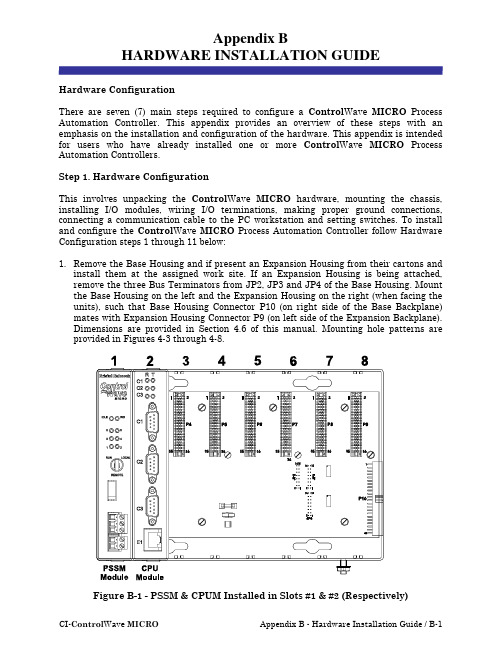
Appendix BHARDWARE INSTALLATION GUIDEHardware ConfigurationThere are seven (7) main steps required to configure a Control Wave MICRO Process Automation Controller. This appendix provides an overview of these steps with an emphasis on the installation and configuration of the hardware. This appendix is intended for users who have already installed one or more Control Wave MICRO Process Automation Controllers.Step 1. Hardware ConfigurationThis involves unpacking the Control Wave MICRO hardware, mounting the chassis, installing I/O modules, wiring I/O terminations, making proper ground connections, connecting a communication cable to the PC workstation and setting switches. To install and configure the Control Wave MICRO Process Automation Controller follow Hardware Configuration steps 1 through 11 below:1. Remove the Base Housing and if present an Expansion Housing from their cartons andinstall them at the assigned work site. If an Expansion Housing is being attached, remove the three Bus Terminators from JP2, JP3 and JP4 of the Base Housing. Mount the Base Housing on the left and the Expansion Housing on the right (when facing the units), such that Base Housing Connector P10 (on right side of the Base Backplane) mates with Expansion Housing Connector P9 (on left side of the Expansion Backplane).Dimensions are provided in Section 4.6 of this manual. Mounting hole patterns are provided in Figures 4-3 through 4-8.Figure B-1 - PSSM & CPUM Installed in Slots #1 & #2 (Respectively)Step 1. Hardware Configuration (Continued)2. Power Supply/Sequencer Module’s (PSSM’s) configuration jumpers must be set for bulkpower (+12Vdc or +24Vdc); and if so equipped, for backup battery usage (see Figures B-2A, B2-2B & B2-2C). Remove the PSSM Module from its carton and install it into Base Housing slot 1, i.e., the first slot from the left end of the installed unit (see Figures B-1A & B-1B). Slot #1 is the first slot, counting left to right, and provides 44-pin female interface connector P1. Power and Watchdog wiring can be performed at this time.However; for safety reasons and to prevent accidental damage to the user’s bulk DC Power Supply, it is recommended that pluggable Terminal Block connectors TB1 and TB2 are not connected to the PSSM until the CPU Module has been installed, wired, and hardware configured. Power Supply-/Sequencer Modules (PSSM) utilize compression-type terminals that accommodate up to #14 AWG wire.Figure B-2A - PSSM Component Identification and TB1 Wiring Diagram(PSSM with System Battery)Figure B-2B - PSSM Component Identification - see Fig. B-2A for and TB1 Wiring (with Display/Keyboard Interface - System Battery on CPU Module)Figure B-2C - PSSM Component Identification see Fig. B-2A for and TB1 Wiring (with Mode Switch & Display/Keyboard Intf. - System Battery on CPU Module)PSSM Connector TB1 provides 3 input connections for bulk power as follows:TB1-1 = +VIN (+10.7V to +20.0V dc for +12V) (+21.7V to +30.0V dc for +24V)TB1-2 = −VIN (Supply Ground)TB1-3 = Chassis Ground (CHASSIS)The Watchdog MOSFET switch is powered via the WDOGIN input of the terminal block, i.e., TB2-1. The switched output is connected to the WDOGOUT output of the terminal block, i.e., TB2-2. WDOGO is a signal generated by the CPU Module when its hardware detects that the regulated 3.3Vdc or 1.8Vdc supplies are out of Spec.Figure B-3 - Watchdog MOSFET Switch Field WiringThe external power source connected to the VI terminal must be referenced to the return point of the input source that powers the PSSM [-VIN or PSGND (TB1-2)].PSSM Connector TB2 provides Watchdog MOSFET Switch Control connections as follows:MOSFET Connections:TB2-1 = VI - Watchdog MOSFET Switch InputTB2-2 = VO - Watchdog MOSFET Switch OutputStep 1. Hardware Configuration (Continued)3. Remove the CPU Module from its carton and configure it. CPU Modules equipped witha System Battery MUST have Jumper JP1 on the Battery Backup Board installed toenable the System Battery. To configure the CPU Module, DIP-Switches must be set for the desired performance options (see Figures B-4A & B-4B. Tables B-1, B-2 and B-3 provide an overview of switch settings.Table B-1 - CPU Bd. Switch SW1 - Force Recovery Mode/Battery EnableFunction Setting - (OFF = Factory Default)UsedSW1-1 NotUsedSW1-2 NotSW1-3 Force Recovery Mode ON = Force recovery mode (via CW Console)OFF = Recovery mode disabledUsedSW1-4 NotTable B-2 - CPU Bd. Switch SW2 - User Configurations Note: Except for SW2-4, ON = Factory DefaultSW2-1 WatchdogEnable ON = Watchdog circuit is enabled OFF = Watchdog circuit is disabledSW2-2 Lock/UnlockSoft Switches ON = Write to Soft Switches and FLASH filesOFF = Soft Switches, configurations and FLASH files are lockedSW2-3 Use/IgnoreSoft Switches ON = Use Soft Switches (configured in FLASH)OFF = Ignore Soft Switch Configuration and use factory defaultsSW2-4 Core UpdumpSee Section 3.6 ON = Core Updump DisabledOFF = Core Updump via use of Run/Remote/Local SwitchTable B-2 - CPU Bd. Switch SW2 - User Configurations (Continued)SW2-5 SRAM Control ON = Retain values in SRAM during restartsOFF = Force system to reinitialize SRAMSW2-6 N/ASW2-7 N/ASW2-8 EnableWINDIAG ON = Normal Operation (don’t allow WINDIAG to run test) OFF = Disable boot project (allow WINDIAG to run test)Table B-3 provides CPU Switch SW3 (COM3) and ECOM Switch SW1 COM5/9 RS-485 communication port settings.Table B-3CPU Bd. Switch SW3 for COM3 & ECOM Bd. Switch SW1 for COM5/9Loopback & Termination Control1 TX+ to RX+ Loopback ON - Only for Diagnostics2 TX- to RX- Loopback ON - Only for Diagnostics3 100 Ohm RX+ Termination ON - End Nodes Only4 100 Ohm RX- Termination ON - End Nodes Only5 N/A ON - Slew Rate Enabled6 (see note 2) Slow Slew RateISO485 ONLYON - Slow Rate EnabledOFF - Fast Rate Enabled7 RX+ Bias (End Node) ON - End Nodes Only8 RX- Bias (End Node) ON - End Nodes OnlyNote 1: Closed = Switch set ONNote 2: Switch SW3 (COM3) = N/AStep 1. Hardware Configuration (Continued)4. Configure/Connect appropriate communication port(s). Connect COMM. Port 1 or 2 ofthe Control Wave MICRO (depending on CPU Switch SW1 settings - see Tables B-2 & B-3) to a Communication Port of a PC (typically PC COMM. Port 1). Note: Control Wave MICRO COMM. Port 1 can only be used if CPU Switch SW2-8 has been set ON.A Control Wave MICRO Process Automation Controller can be configured as a Masteror Slave node on either a MODBUS network or a BSAP network. Up to four com-munication ports are contained on the Control Wave MICRO CPU Module and are designated as follows:CPU Module:COM1 - Port 1: CPU Bd. J3, PC/AT 9-Pin Male D-Sub - RS-232COM2 - Port 2: CPU Bd. J4, PC/AT 9-Pin Male D-Sub - RS-232COM3 - Port 3: CPU Bd. J5, PC/AT 9-Pin Male D-Sub - RS-485 - Supported by SW3 Ethernet Port 1: CPU Bd. J6, 8-Pin RJ-45 - Twisted Pair 10/100BaseT (Optional)Figure B-4A - CPU Module Component Identification Drawing(CPU without System Battery & shown with Ethernet Port)Figure B-4B - CPU Module Component Identification Drawing (CPU with System Battery & shown without Ethernet Port)Expansion Communications Module:COM4, COM5, COM6 & COM7 on 1st ECOM Bd., - assigned to Base Housing Slot #3 COM8, COM9, COM10 and COM11 on 2nd ECOM Bd., assigned to Base Housing Slot #4 COM4/8 - Port 1: ECOM Bd. J1, PC/AT 9-Pin Male D-Sub - Both RS-232COM5/9 - Port 2: ECOM Bd. J2, PC/AT 9-Pin Male D-Sub - Both RS-485COM6/10 - Port 3: ECOM Bd. Piggy-back Radio Module (FreeWave or MDS TransNet Spread Spectrum Modem) Antenna connector provided (Optional)COM7/11 - Port 4: ECOM Bd. Piggy-back Modem Module (Multitech 56KB PL/PSTN Modem) RJ-11 connector provided (Optional)Communication Ports COM1, COM2, COM3, COM4, COM5, COM8 and COM9 support serial asynchronous operation. Communication Ports COM1, COM2, COM4 and COM5 support RS-232 while COM3, COM5 and COM9 support RS-485 operation. Com-munication Ports COM4/8, COM5/9, COM6/10 and COM7/11 reside on optional Expansion Communications Modules (ECOM1/2). ECOM1 must reside in Base Chassis Backplane Slot #3 while ECOM2 must reside in Base Chassis Backplane Slot #4. ECOM Modules have one RS-232 Port and one RS-485 Port. Additionally, an ECOM Module may optionally contain a 56Kbaud PSTN Modem and/or a Spread Spectrum Modem (Radio). Any non-Ethernet communication ports can be configured for local communications, i.e., connected to a PC loaded with Control Wave Designer and OpenBSI software. The pin labels for the 9-pin, RS-232/485 interface are provided in Table B-4.Table B-4 - RS-232 Ports COM1/2/4/8 and RS-485 Ports COM3/5/9Connector Pin Assignments1 DCD Data Carrier Detect Input N/A2 RXD Receive Data Input RXD- Receive Data - Input3 TXD Transmit Data Output TXD- Transmit Data - Output4 DTR Data Terminal Ready Output TXD+ Transmit Data + Output5 GND Signal/Power Ground GND/ISOGND* Ground/Isolated Ground*6 DSR Data Set Ready Input RXD+ Receive Data + Input7 RTS Request To Send Output N/A8 CTS Clear To Send Input N/A9 N/A N/A* ISOGND on Isolated RS-485 Ports Only!Remove any Expansion Communication Module and configure its Jumpers as required (see Figures B-5A and B-5B). Install each Expansion Comm. Module into the appropriate Control Wave MICRO Base Housing Communication I/O Slot. Expansion Comm. Modules may reside in Control Wave MICRO Base Housing Slots #3 and #4 ONLY (1st ECOM resides in Slot #3, 2nd ECOM resides in Slot #4). Expansion Comm. Modules may not reside in Expansion Housings.Figure B-5A - ECOM Module Component Identification Diagram #1Figure B-5B - ECOM Module Component Identification Diagram #2 Table B-5 - Ethernet 10/100Base-T CPU Module Pin Assignments Pin # Description Pin # Description1 Transmit Data+ (Output) 5 Not Connected2 Transmit Data- (Output) 6 Receive Data- (Input)3 Receive Data+ (Input) 7 Not ConnectedConnected4 NotConnected 8 NotNote: TX & RX are swapped at Hub’s.Figure B-6 - Communication Port RS-232 Cable Wiring DiagramFigure B-7- Point-to-Point 10/100Base-T Ethernet CableFigure B-8 - Standard 10/100Base-T Ethernet Cable (CPU Module to Hub) Spread Spectrum Modem PortAn optional Spread Spectrum Modem (Radio) is available on each Expansion Communications Module (mounted piggy-back) and is assigned port status as follows: COM6 for ECOM1 and COM10 for ECOM2. There are two unique radios offered. These radios will only communicate with their own brand of radio, i.e., FreeWave radios are not compatible with MDS radios. DTE/DCE serial data can be clocked into (transmit) or out of (receive) the radio at a rate up to 115.2kHz.Radios are user installed onto the ECOM Module (see Figure B-5A) and their as-sociated Ports are setup during installation in the Ports Page of the Flash Con-figuration Utility. The Flash Configuration Utility is accessed via NetView or LocalView.FreeWave® Spread Spectrum Wireless Data Transceiver:Operates in the 902 to 928 MHz range (20 miles).Microwave Data System Inc. MDS TransNET OEM™ Spread Spectrum Data Transceiver: Operates in the 902 to 928 MHz range (20 miles).Installation steps below support user installation and configuration of a Spread Spectrum Modem.•Mount the radio (Spread Spectrum Modem) onto the Expansion Comm. Module. Remove the nut and washer from the internal coaxial RF cable supplied with the ECOM Module. Remove the plug from the front of the ECOM Cover and insert the in-ternal coaxial RF cable’s SMA connector (straight end with flat area on top) through the rear of the ECOM Cover. Install the washer and nut to secure the internal coaxialRF cable to the front of the ECOM Cover. Install the other end of the internal coaxial RF cable to the radio’s RF antenna connector. Install the Expansion Comm. Module into Slot 3 or 4 of a base Control Wave MICRO unit. Install the user supplied coaxial RF cable between the ECOM Cover’s SMA connector and the remote antenna.• For FreeWave Radio:Follow the Tuning Transceiver Performance” section of the FreeWave Technologies Inc. FreeWave Spread Spectrum Wireless Data Transceiver User Manual to configure the radio.For MDS Radio:Refer to section 3.3 “Initial Power-Up & Configuration” within the MDS TransNet OEM Integration Guide and if necessary for more information on connecting a PC terminal and preparing it for use, refer to section 9.0 “PROGRAMMING REFERENCE.”Note:To invoke the setup program, connect the radio (via ECOM1 port COM4 or ECOM2 port COM8) to a terminal program (such as Hyperterminal) via a null modem cable (see Figure B-6), put the radio into setup mode and set the parameters for the terminal to those of Table B-6 below. The setup program is invoked by connecting Pins 2 and 3 of ECOM Bd. Jumper Post JP2 via a Suitcase Jumper.Table B-6 - Radio Setup Menu Terminal SettingsBaud Rate 19,200Data Rate 8Parity NoneStop Bits 1Parity Check None/OffCarrier Detect None/OffFlow Control Xon/Xoff56K PSTN Modem PortAn optional 56K PSTN Hayes type Modem can be mounted piggy-back on each Expansion Communications Module and is assigned port status as follows: COM7 for ECOM1 and COM11 for ECOM2. The Model MT5634SMI Modem module is manufactured by MultiTech System and can be user configured for PSTN operation. DTE/DCE serial data can be clocked into (transmit) or out of (receive) the modem at a rate up to 115.2kHz.Modems are supplied in kit form with all the hardware required for user installation onto an Expansion Communications Module. Figure B-5A shows the modem mounted on the Expansion Comm. Module. Modems are user installed onto the ECOM Module and their associated Ports are setup during installation in the Ports Page of the Flash Configuration Utility. The Flash Configuration Utility is accessed via NetView or LocalView.A Terminal Emulation program such as Hyperterminal is used to profile the modem via AT commands. Users typically use AT commands only when checking the modem’sactive or stored profile or when reconfiguring a modem, e.g., to turn auto answer on or off, etc.Step 1. Hardware Configuration (Continued)5. Remove any I/O Modules from their cartons and configure each one for its intendedapplication. After configuration, install them into the Control Wave MICRO Housing.I/O Modules may reside in a Control Wave MICRO Housing as follows:Base Housings - Slots 3 & 4 (in lieu of Expansion Comm. Modules) & Slots 5 through 8 Expansion Housings - Any SlotFigure B-9 - Isolated DI Module Configuration Diagram(See Figure B-11 for Remote Term. Block Assignments)Figure B-10 - Isolated DO Module Configuration Diagram (See Figure B-11 for Remote Term. Block Assignments)Figure B-11 - Remote Isolated DI & Isolated DO Term. Block AssignmentsFigure B-12 - Non-Isolated DI/O Module Configuration Diagram (See Figure B-15 for Remote Term. Block Assignments)Figure B-13 -Non-isolated AI/O Module Configuration Diagram (See Figure B-15 for Remote Term. Block Assignments)Figure B-14 - Non Isolated HSC Module Configuration Diagram (See Figure B-15 for Remote Term. Block Assignments)Figure B-15 - Remote Non-isolated DI/O, AI/O & HSC Term. Block AssignmentsFigure B-16 - Isolated AI Module Configuration DiagramFigure B-18 - Isolated AO Module Configuration Diagram (See Figure B-19 for Remote Term. Block Assignments)Figure B-20 - Isolated Vac DI Module Configuration DiagramFigure B-21 – Relay Isolated Vac/Vdc DO Module Configuration DiagramFigure B-22 - Non-isolated Mixed I/O Module Wiring Diagram(See Figure B-23 for Mixed I/O Module Configuration Diagram)Step 1. Hardware Configuration (Continued)6. Install I/O wiring to each I/O Module (see Figures B-9 through B-23).7. Install a ground wire between the Chassis Ground Lug and a known good Earth GroundControl Wave MICRO Housings are provided with a Ground Lug that accommodates up to a #4 AWG wire size. A ground wire must be run between the Chassis Ground Lug and a known good Earth Ground. The cases of the various Control Wave MICRO Modules are connected to Chassis Ground when they have been installed and secured via their two Captured Panel Fasteners. As an extra added precaution, it is recommended that a #14 AWG wire be run from PSSM Power Connector TB1-3 (Chassis Ground) to the same known good Earth Ground.FIELD CIRCUITRYDiscrete InputField TB#1Dry Contact -Internally Sourced DI Wiring DiagramFIELD Field Wiring DiagramFIELD Field Driven Single-ended DIWiring Diagram9TB1TB21234567891012345678910DI/O ModuleLEDAssignmentsDI1DI2DI3DI4DI5DI6DI7DI8DI9DI10DI11DI12DO1DO2DO3DO4The following considerations are provided for the installation of Control Wave MICRO system grounds:• Chassis Ground Lug to Earth Ground wire size should be #4 AWG. It is recommended that stranded copper wire is used and that the length should be as short as possible.•This ground wire should be clamped or brazed to the Ground Bed Conductor (that is typically a stranded copper AWG 0000 cable installed vertically or horizontally).•The wire ends should be tinned with solder prior to insertion into the Chassis Ground Lug. Note: Use a high wattage Soldering Iron.•The ground wire should be run such that any routing bend in the cable has a minimum radius of 12-inches below ground and 8-inches above ground.Step 1. Hardware Configuration (Continued)8. If not already done, install Watchdog MOSFET Switch wiring if required (see Step 2and Figure B-3).9. Connect Bulk DC Power to the Control Wave MICRO’s PSSM Module (see Step 2 andFigure B-2A/B/C).10. Install the Bezel(s) so that Comm. and I/O Modules are covered.11. Apply power to the Control Wave MICRO controller by setting the Power Switch on thePSSM Module to the ‘I’ position. After receiving the Application Load (see Steps 2 through 7 and the Topic Downloading the Application Load that follows), the Control Wave MICRO Process Automation Controller will be ready for on line operation.Step 2. Software Installation on the PC WorkstationControl Wave Designer software must be installed on the PC. This is accomplished by installing the Control Wave Designer Package from the Open BSI CD ROM.If you will be including the Control Wave MICRO in an OpenBSI network that requires Netview software, you should also install the Open BSI Network Edition. For information on minimum system requirements and more details of the installation, see the installation procedure in Chapter 2 of the Open BSI Utilities Manual (document # D5081).If you have an older version of ControlWave Designer already installed: Beginning with Control Wave Designer Version 3.3, the copy protection key (dongle) is NOT required. Prior to installing Control Wave Designer 3.3 or newer, you MUST remove the hardware dongle from the parallel port of your PC workstation. Otherwise, when you subsequently start Control Wave Designer, it will operate only in ‘DEMO’ mode, and will limit the available system resources.IMPORTANT:When you start ControlWave Designer, you will be reminded to register themore information on the registration process, see Chapter 2 of the Open BSI Utilities Manual (document# D5081).Step 3. Establish Communications using either LocalView or NetView, and run the Flash Configuration UtilityCommunications must be established with the Control Wave MICRO using either Local-View or NetView. Once communications have been established, the Flash Configuration Utility must be run in order to configure user account parameters, and to configure the Control Wave MICRO communication ports. An overview of this process is included in Part 2 of the ControlWave Quick Setup Guide (document # D5084). Detailed information on the Flash Configuration Utility and LocalView is included in Chapter 5 of the Open BSI Utilities Manual (document # D5081). NetView is described in Chapter 6 of that same manual.Step 4. Create an Application-Specific Control Strategy in Control Wave DesignerAt this point, you can create your application-specific control strategy using Control Wave Designer. This involves opening a new project using the ‘CWMicro’ template, defining I/O boards using the I/O Configurator, and creating a program using one or more of the five supported IEC 61131 languages (FBD, ST, SFC, LD, or IL). Some of these languages are text based, others use graphical diagrams. The choice is up to you, depending upon your particular application.The Control Wave MICRO Quick Setup Guide (document # D5124) includes a simple LD example. Additional examples are included in the manual, Getting Started with Control Wave Designer (document # D5085). More detailed information about Control Wave Designer and IEC 61131 is included in the Control Wave Designer Reference Manual (document # D5088).The ACCOL3 Firmware Library, which is automatically accessible through the template referenced above, includes a series of function blocks which perform a variety of process control and communication functions. These can be included within your program to perform various duties including PID control, alarming, calculations, etc. Detailed information about each function block is included in the Control Wave Designer on-line help files.On the variables declaration page(s) in Control Wave Designer, you will need to mark any variable you want to make accessible to external programs, such as Open BSI’s DataView utility, as “PDD”. Similarly, any variables which should be collected into a database, or exported using the O LE for P rocess C ontrol (OPC) Server must be marked as “OPC.”Variables marked as OPC can be built into a text file by the Open BSI Signal Extractor. The text file can then be used in the creation of a database for human machine interface (HMI) software such as OpenEnterprise, or Iconics’ Genesis. These HMI software packages require that the "Datatype conversion enable" option be selected when generating the file using Signal Extractor. Information about the Open BSI Signal Extractor is included in Chapter 12 of the Open BSI Utilities Manual (document # D5081).Once the program has been created, it is assigned to an executable task. The entire project is then saved and compiled.NOTE: From this point on, the order of steps may be varied, somewhat, depending upon the requirements of the user's application.CI-Control Wave MICRO Appendix B - Hardware Installation Guide / B-31Step 5. Create Application-Specific Web Pages (OPTIONAL)Control Wave MICRO Process Automation Controllers support a set of standard web pages for data collection configuration purposes, and for access to communication statistics maintained in the controller. Optionally, additional user-created web pages may be created to allow a customized human machine interface (HMI). A series of ActiveX controls for data collection and configuration are provided on the Open BSI CD which can be included as part of these user-created web pages. For information in the ActiveX controls, see the Web_BSI Manual (document # D5087).You can use whichever HTML creation package you want to create the pages, however, all Control Wave MICR O related web pages (whether standard or user-created) must be viewed within Microsoft® Internet Explorer. The web pages may reside either on a PC workstation, or they can be downloaded into FLASH memory at the Control Wave MICRO. If stored at the Control Wave MICRO, you must use the ControlView utility to retrieve the pages (using FTP) for viewing in Internet Explorer.Step 6. Create an Open BSI Network Containing the Control Wave MICRO Unit, or add the Control Wave MICR O unit to an Existing Open BSI NetworkIn order for the Control Wave MICRO unit to function as part of a Bristol Babcock network, it is necessary to include it in the Bristol Babcock network.If no Bristol network exists:You will need to start Open BSI’s NetView software on the PC workstation in order to define a Bristol network. A series of software wizards are used to define a Network Host PC, a network, and the RTUs (controllers) belonging to the network. Finally, communication lines must be specified which handle the address assigned to the Control Wave MICRO controller. Chapters 3 and 4 of the Open BSI Utilities Manual (document # D5081) include ‘quick start’ examples for performing these steps. More detailed information is included in the NetView chapter (Chapter 6) of the same manual.If a Bristol network already exists:You will need to add the Control Wave MICRO Process Automation Controller to the existing network using NetView’s RTU Wizard. Chapter 6 of the Open BSI Utilities Manual (document # D5081) includes different sub-sections depending upon whether you are adding the unit to a BSAP network, or an IP network.Step 7. Download the Application-specific ControlWave Project into the Control-Wave MICRO UnitEither Control Wave Designer or the Open BSI 1131 Downloader allows you to download your completed Control Wave project (application load) file into the Control Wave MICRO unit. Users download the project into the BOOT Project area of FLASH memory; this ensures that if the Control Wave MICRO unit has been reset, or if there has been a failure of the backup battery, the project can be restarted from the beginning, i.e., from the BOOT Project in FLASH memory.The Open BSI 1131 Downloader also allows the user to download user-created web pages into Control Wave MICRO units. Alternatively, File Transfer Protocol (FTP) can be used to send web pages to the controller. To download the application load, see section titled Downloading the Application Load.B-32 / Appendix B - Hardware Installation Guide CI-Control Wave MICRODownloading the Application LoadA Control Wave MICRO Process Automation Controller must receive its configured ap-plication load before it can be placed into operation. This will require connection of the Control Wave MICRO to a PC running Windows NT (4.0 or higher), Windows 2000 or Windows XP Professional and equipped with Control Wave Designer software & OpenBSI software. Configuration of the application load must be performed by an individual familiar with the various programming tools. The following software user documentation is referenced: Getting Started with Control Wave Designer Manual - D5085Control Wave Designer Reference Manual - D5088OpenBSI Utilities Manual - D5081Control Wave Designer Programmer’s Handbook - D5125An application load download can be initiated, i.e., from Control Wave Designer, or from the OpenBSI 1131 Downloader for Control Wave MICRO Nodes.1.Set the PSSM’s RUN/REMOTE/LOCAL Switch (Key Operated) or Mode Switch as follows:- If the PC is connected to a Control Wave MICRO Communication Port that has been configured as an IP or OpenBSI Network Port, set the PSSM’s RUN/REMOTE/-LOCAL Switch to the ‘REMOTE’ position or the PSSM’s Mode Switch (SW1) for Local Mode, i.e., SW1-1 UP (Open) and SW1-2 DOWN (Closed).- If the PC is connected to a Control Wave MICRO Communication Port that has been configured as a Serial Port, set the PSSM’s RUN/REMOTE/LOCAL Switch to the ‘LOCAL’ position or the PSSM’s Mode Switch (SW1) for ‘Local Mode,’ i.e., SW1-1 set to the UP(Open) position and SW1-2 set to the DOWN(Closed) position.Note: From the factory, COM1 defaults to 115.2 kbd (RS-232) using the Internet Point to Point Protocol (PPP). Don’t connect COM1 to a PC unless the PC’s RS-232port in question has been configured for PPP.2.Once the Control Wave MICRO project has been defined, communications and con-figuration parameters have been set perform the download according to either ‘Control Wave Designer’ (see D5088 - chapter 11) or the ‘Open BSI 1131 Downloader’ (see D5081 - Chapter 7).3. After the download has been completed set the PSSM’s RUN/REMOTE/LOCAL Switch tothe RUN position or leave the PSSM’s Mode Switch (SW1) in the ‘Local Mode’ position i.e., SW1-1 set UP(Open) and SW1-2 set to the DOWN(Closed).LED ChecksAll Control Wave MICRO Modules contain light emitting diodes (LEDs) that provide operational and diagnostic functions. Control Wave MICRO LED designations and func-tions are provided in Table B-7. A brief synopsis of the individual module LEDs is provided as follows:PSSM: 1 IDLE, 1 Watchdog & 6 System Status LEDs - (1 PWRGOOD LED*)CPUM: 2 LEDs per Comm. Port = 6, 2 LEDs per Ethernet Port = 2ECOM1: 2 LEDs per Comm. Port = 8ECOM2: 2 LEDs per Comm. Port = 8AI/OM: NoneIDIM: 1 LED per IDI = 16CI-Control Wave MICRO Appendix B - Hardware Installation Guide / B-33。
阀组间RTU简介

2 3 4
块 面 块
1 1 1
CPU技术指标 CPU技术指标
项目 处理器 非易失性存储器 集成功能 通信接口 工作环境 工作电源 指标 32位处理器 在无供电情况下,Flash存储器保存数据3年 看门狗定时器 1*RS232 + 1*RS485 工作温度:-40℃~+ 工作湿度:0%~95%RH 不结露 24VDC,工作电流<100mA
仪表通信地址(功号11) 仪表通信地址(功号11) 11 仪表通信地址用以在RS485通信时, 仪表通信地址用以在RS485通信时,确定仪表自身位置 RS485通信时 ,区别于其他流量仪表的编号。在正常测量状态下,按 区别于其他流量仪表的编号。在正常测量状态下, ●一下,屏幕显示序号00,下面0000,再按▲11下,屏幕 一下,屏幕显示序号00,下面0000,再按▲11下 00 0000 显示序号11,下面显示255。再按●一下,头一位数2 显示序号11,下面显示255。再按●一下,头一位数2开始 11 255 闪烁,这时按▲ 闪烁,这时按▲或▼就可以设置流量控制器的地址,按 就可以设置流量控制器的地址, 进行移位。设置完成后, 进行移位。设置完成后,按●确认。 确认。
通信方式
1、与安控井场主RTU通信 与安控井场主RTU通信 RTU (1)方式1:ZIGBEE接口、无线非透传方式 2 、与其他厂家主 与其他厂家主RTU通信 通信 (1)方式1:ZIGBEE接口、无线透传方式 (2)方式2:RS485接口、有线透传方式 (3)方式3:RS485接口、无线透传方式
AI0 AI1….AI5
Super32Super32-L309CQ
RS485
无线通 信模块
稳流配水装置1 汇 管 压 力 稳流配水装置2 稳流配水装置3 稳流配水装置4 稳流配水装置5
RTU应用场景及建议

RTU应用建议
一、终端燃气应用场景
●小型配气站:数据采集(流量计4路、进出站汇管压力6路、
可燃1路)+阀门控制2路+电动调压1路,市电
●干线撬装:数据采集(流量计2路、进出站压力1路、可选可
燃探测),太阳能或锂电
●用户计量撬:数据采集(流量计2路、进出站压力1路、可选
可燃探测)太阳能或锂电
●阀室、阀井:数据采集(压力监测1路、可燃探测)锂电
●管网监控点(中压、低压):数据采集(压力监测1路)太阳
能或锂电
针对不同的应用场景核算不同的RTU功耗,主要说明低功耗,灵活配置。
二、功能配置
1、建议讲解时从RTU本身功能开始讲述,然后是增值配置
(如:多种供配电模式、4G路由、协议、蓝牙、APP等)。
2、建议加大物联网的宣传,可举例五矿一处现有物联网项目,
产品设计已考虑后期物联扩展。
3、目前基于运营商的物联NBIOT技术推广是一个趋势,可加
大对这个融合性说明。
三、产品配置
建议产品配置可多元化
1、整体解决方案,成套提供;
2、按需配置核心模块,自由组合;
3、增值类功能,按客户需求配置;。
- 1、下载文档前请自行甄别文档内容的完整性,平台不提供额外的编辑、内容补充、找答案等附加服务。
- 2、"仅部分预览"的文档,不可在线预览部分如存在完整性等问题,可反馈申请退款(可完整预览的文档不适用该条件!)。
- 3、如文档侵犯您的权益,请联系客服反馈,我们会尽快为您处理(人工客服工作时间:9:00-18:30)。
BB RTU阀室控制系统技术方案1.概述西气东输泰安支干线站控系统拟采用以计算机为核心的监控及数据采集(SCADA-Supervisory Control And Data Acquisition)系统。
其中在各监控阀室、监视阀室和高位检测点分别设置远程终端装置(RTU)作为SCADA系统的远方控制单元。
RTU是保证天然气输送管道、输油管道自动化监控系统正常运行的基础,系统投产运行后可以达到在调度控制中心(MCC)或备用调度控制中心(SCC)对全线进行自动监控的技术水平。
2.系统描述BristolBabcock公司在全球自控系统的领导地位、丰富的石油天然气及管道行业经验、以及独特的系统设计方法保证我们为各监控阀室、监视阀室和高位检测点RTU部分提供一整套解决方案,并且保证该解决方案是最佳的解决方案。
各监控阀室、监视阀室和高位检测点RTU均采用BB公司的ControlWave Micro控制器。
ControlWave Micro控制器CPU 集成了1个RS232、1个RS485串口和2个100∕10MB以态网口。
阀室RTU与通信系统之间采用光通信,将RTU的数据同时向上下游的站控制系统发送,光通信通道任一处发生故障时,均可保证RTU的正常通信,提高整条管线的安全性。
BristolBabcock公司的ControlWave控制器组态软件ControlWave Designer工作在基于32位的Windows系统,软件编程支持复制、粘贴、自定义工具栏、快捷方式、I/O仿真、程序离线测试、程序打印等操作,同时软件编辑器提供各种操作的向导帮助,可以使操作者容易的完成如:I/O的组态、函数和功能块的添加删除、关键字的添加、变量和数据类型的定义等工作。
组态软件ControlWave Designer提供五种编程语言(ST, FDB, LD, SFC, IL)。
3.系统功能远程终端装置--RTU➢对现场的工艺变量进行数据采集和处理;➢监控线路紧急截断阀;➢供电系统的监控;➢采集和处理阴极保护站的相关变量;➢可燃气体的监视和报警;➢数据存储及处理;➢逻辑控制;➢紧急停车(ESD);➢为调度控制中心提供有关数据;➢接受并执行调度控制中心下达的命令等。
4.系统硬件描述4.1 远程终端装置 (RTU-ControlWave Micro)ControlWave Micro是集成了PLC,RTU和PAC 的优点与一体的可编程混合控制器,从小规模、中等规模的应用到大规模的应用场合都能使控制系统性能达到最大化。
它也能无缝的兼容ControlWave系列其它产品从而可以实现整个控制系统的结构最优化。
另外由于产品具有其体积小、功耗低、坚固耐用的特点,完全能满足苛刻的工厂控制及远程SCADA应用环境。
1.C ontrolWave Micro特点:➢ARM处理器提供卓越的性能和超低功耗➢IEC 61131-3编程标准并集成有ACCOL III过程控制功能块库➢可选择的10/100 Mbps自适应以太网口➢多达11个串行通讯接口(包括可选配的内置调制解调器和电台通讯端口)➢3,4,8槽基本机架,2,4,8槽扩展机架➢混合输入/输出卡件满足低成本的场合应用➢可选配的隔离型输入/输出模块➢硬件密码锁拒绝无权限的人访问➢工作温度范围宽(-40到70 ℃)➢适用于Class I,Div.2危险区域,通过CE认证➢开放式的编程、网络组态及通讯环境ControlWave Micro 150CPU➢32位ARM 9 处理器:150MHz➢睡眠模式满足低功耗应用➢程序运行内存:4 MB SDRAM➢数据内存:1M SRAM(断电电池保护)➢程序、历史归档数据及文件存储内存8M或16M FLASH RAM➢实时时钟➢硬件密码锁保证安全切换ControlWave Micro 150CPU2. 通讯部分CPU➢CPU上有两个RS-232、一个RS-485端口,标准9针D型接口,波特率可达115.2KB。
➢一个或二个可选择10/100M以太网口,RJ45接口。
可选配扩展通讯模块➢每一个CPU机架上最多可插两个通讯扩展模块➢每个扩展通讯模块有以下通讯端口:➢一个RS-232和一个RS-485端口,标准9针D型接口,波特率可达115.2 KB,RS-485端口隔离电压500VDC ➢一个可选择的内置调制解调器。
➢一个可选择的900兆赫内置扩频电台系统控制模块➢5.4V~17V直流输入或者10.7V~30V直流输入➢电源故障检测及恢复装置➢预留LCD显示/操作面板连接接口➢LED状态指示灯:6个故障指示灯,1个看门狗灯,1个CPU IDLE灯及各通讯口收发指示灯。
机架➢3槽基本机架:8.64 cm x 15.24 cm x 14.7 cm➢4槽基本机架:11.43cm x 15.24 cm x 14.7 cm➢8槽基本机架:22.86cm x 15.24 cm x 14.7 cm➢2槽扩展机架:5.7 cm x 15.24 cm x 14.7 cm➢4槽扩展机架:11.43cm x 15.24 cm x 14.7 cm➢8槽扩展机架:22.86cm x 15.24 cm x 14.7 cm环境要求工作温度范围:-40到70℃,储存最高温度85℃➢相对湿度:15-95%无冷凝➢震动:1.0g(10-150Hz), 0.5g(150-2000Hz)➢危险区域认证:无电感情况下工作在Class I, Division 2Groups C & D场合➢抗干扰:3V/m – 80 MHz 到1000Mhz (EN50082-2)功耗➢不带以太网口的Micro 33 CPU :0. 1W➢不带以太网的Micro 150CPU :1W➢带以太网的Micro 150CPU :1.2W➢系统控制模块:0.08W➢扩展通讯模块:0.53W➢Freewave电台:发送3.8W,接受1.2W➢MDS TransNet radio :发送7W,接受1.6W➢拨号调制解调器:0.8W5.系统软件概述RTU编程组态软件――ControlWave Designer组态软件ControlWave Designer工作在基于32位的Windows系统,软件编程支持复制、粘贴、自定义工具栏、快捷方式、I/O仿真、程序离线测试、程序打印等操作,同时软件编辑器提供各种操作的向导帮助,可以使操作者容易的完成如:I/O的组态、函数和功能块的添加删除、关键字的添加、变量和数据类型的定义等工作。
组态软件ControlWave Designer 提供五种编程语言(ST, FDB, LD, SFC, IL)ControlWave Designer带ACCOL III功能块库为了减少工程量和开发时间,我们软件采用了PLC编程的国际标准IEC61131-3。
ControlWave Designer是完全满足IEC61131-3编程环境的ControlWave系列产品编程组态软件。
ControlWave Designer包括五种IEC61131-3标准编程语言既功能块图、结构文本、顺序功能块图、梯形图、命令列表语言。
它们可以满足批量、连续及离散控制。
ControlWave Designer包括200多个基于IEC61131-3标准的功能块和函数,包括:➢Flip-flops, Counters & Timers➢梯形图函数:coils 、contacts等等➢数学运算及布尔型函数:Sine, Cosine, Add, Sub, Square Root, And, Or等➢选择比较函数及功能块:Min, Max, Greater than, Equal, Less than等等➢类型转换函数:Integer to Real, Boolean to Word等等ACCOL III功能块库除了基本的功能块及函数外,ControlWave Designer还集成了基于二十多年SCADA及过程控制经验不断完善的ACCOL III功能块库。
ACCOL III功能块库包括60多个用于石油天然气、水及污水、过程计量及控制应用场合的功能块,同时将来还会集成更多实用有意的功能块。
ACCOL III功能块库主要包括:➢平均值计算、比较计算、累积值计算➢顺序计划功能块➢PID及Lead/Lag➢AGA天然气流量计算、液体流量计算➢文件处理除此之外,可以利用ControlWave Designer软件编程组态实现带时间标签的报警及历史数据在控制器中的存储,当设备与外界通讯中断恢复后,实现数据的回填。
6. ControlWave Micro的有效性分析1. 平均无故障时间(Mean Time Between Failures,MTBF):在此我们以长庆-呼和浩特原油管线1#监控阀室RTU为例来计算系统的有效性。
1#监控阀室ControlWave Micro控制器总共包括1个CPU模块、1个机架、1个电源模块、2个AI模块、1个DI模块、1个DO模块,整个系统的平均无故障工作时间计算如下:2. 平均故障修复时间(MTTR):可以达到99.9981%,由此可见为本项目所配置的Contro Wave Micro控制器的有效性都能满足配置要求。
7. I/O Points Summary一. 泰安支干线工程RTU 系统I/O 列表DI (16) 15 30% 20 2 32 DO (16) 7 30% 10 1 16。