软物质chap_3-1
软珊瑚Nephthea sp.次级代谢产物生物碱的研究

软 珊 瑚 N p te p 次 级 代 谢 产 物 生 物 碱 的 研 究 ehh as.
王 长 军 , 小 建 , 石 海 廖 徐
( 暨南大 学化 学 系 , 广东 广州 5 03 ) 162
摘要 : 次从 白蕙软珊瑚 N p te .中分离得到含硒 元素的已知化合物二苯 基硒 醚 ( ) 同时分离得到 已知 首 ehhas p 1,
生物 碱 , 1的发 现对 进一 步研 究 软珊瑚 对 硒 元素 代
谢 具 有一 定 的生理 意 义 。
备受 化 学家 和药 理学 家 的 广泛 关 注 L 。生物 碱 作 2 J
1 实 验 部 分
1 1 样 品 .
为天 然产 物 家族 重要 的一 类 , 因其 数 量 众 多 , 构 结
样 品软珊 瑚 Np te p ehha s.于 2 0 0 7年 5月 采 自
中 国湛江硇 洲 岛 , 属 由荷 兰 阿姆斯 特丹 大 学 R b 种 o v nSet 授鉴 定 。标 本 现 保存 于 暨 南 大学 化学 a os 教 系有机 化学 教研 室 , 号为 2 0 -1 编 07 。 0 国 Fn ia ingn公 司 Tae G — rc C MS气 一 联 用 仪 ; 磁 质 核
上 检 测 , 剂 为 C C, 内 标 为 T ; 层 色 谱 溶 D 1, MS 薄
收 稿 日期 :00 1 —5 修 回 日期 :0 -21 2 1—21 ; 2 1 0 -9 1
基金项 目: 国家 8 3基金资助项 目(0 6 A 9A0 ) 国家 自然科学基金资助项 目( 0 7 0 8 6 2 0 A 0 7-8 ; 2 7 24 ) 联 系人简介: 徐石海( 9 7), , 16 - 男 教授 , 主要研究方 向:天然产物化学 。E i: uh nleu c ma t s@ji d . n lx .
软物质在生物制造中的应用

软物质在生物制造中的应用随着科技的不断发展,软物质作为一种新兴的材料,被越来越多地应用于生物制造领域中。
软物质的特点是具有高度可调节性和自组装能力,能够模拟生物体内的柔软、可适应性的特性,因此被广泛应用于生物制造中的各个环节。
1. 生物传感器通过软物质材料的信号识别机制,可以制造出高度敏锐、灵敏的生物传感器。
软物质材料可以通过对多元化的刺激(如温度、pH值、电场、磁场等)的响应产生形态变化或导致颜色变化等效应,因此可以用于精准地检测生物样本中的分子和化合物,实现诊断和检测功能。
2. 医疗工具软物质材料的特点是柔软、伸展,其机械性能与人体组织相近,可以用于设计和制造具有良好生物适应性的医疗工具。
例如,瘢痕修复材料、软骨修复材料、动脉支架和心脏瓣膜等。
这些医疗工具均能通过模拟人体内部的柔软性和可调节性,减轻疼痛不适,提高治疗效果。
3. 纳米材料载体软物质材料能够充分调节纳米颗粒的表面化学特性,可用于制造纳米药物载体。
通过改变软物质的结构、组分及化学键等,可以实现药物释放的位置选择、释放速率调节,从而实现精准治疗,并减少对人体正常细胞的毒性副作用。
4. 组织工程软物质材料有独特的生物相容性、可支配性与自组装能力,因此广泛应用于组织工程领域。
通过与细胞相互作用,可以设计出能够形成合成组织的具有预定结构和功能的材料。
例如,可以利用蛋白质和多糖类物质制备出高粘度和高弹性的胶体材料。
这些胶体材料可以模拟细胞外基质的生物组织环境,实现体外重建组织和组织修复。
总之,软物质材料作为一种高度可调节和可自组装的材料,被广泛应用于生物制造领域。
在生物传感器、医疗工具、纳米材料载体和组织工程领域等多个应用领域都具有广泛的应用前景,为我们的生命科学研究与生产创造更为多元化和富有创新性的方向。
材料物理课件4软物质SoftMatter

2021/2/8
20
谢谢观赏
共同学习相互提高
2021/2/8
3
4 软物质: Soft Matter
软物质大多来自于有机物质,其结构常常介于 固体和液体之间,从宏观尺度看不象晶体结构那样 有完美的周期性。从原子、分子尺度看是完全无序 的,但在介观尺寸下存在规则的结构。
2021/2/8
4
4 软物质: Soft Matter
软物质之所以表现出与固态和液态不同的特性, 在于介观尺度下这种有序结构的出现:一方面,决 定流体的热涨落和动力学相互作用支配着系统的行 为;另一方面,介观尺度下受约束结构显示出类似 于固体的行为。这两者共同的作用支配和操纵了软 物质独特的性质。
2021/2/8
6
4 软物质: Soft Matter
常见的一些软物质体系: 高分子聚合物、液晶、胶体、乳液、超分
子材料(双亲性分子)、以及生物大分子等。
2021/2/8
7
2021/2/8
8
2021/2/8
9
F = H - TS
2021/2/8
10
2021/2/8
11
软物质自组织的形式
1. 超分子自组装
软物质体系由于附加自由度的作用可以自组织, 最后形成附加自由度有序的自组织结构。
2021/2/8
2
4 软物质: Soft Matter
在外界作用下软物质的结构之所以发生根本性 的变化从而导致剧烈的效果,这表明软物质是有其 内部结构的。
软物质也被称为为复杂流体或结构液体,主要 就是因为软物质在其柔软的背后存在着复杂的、有 结多重构的特性。
2021/2/8
12
ห้องสมุดไป่ตู้
3R Anyty Microscope 03W 移动端软件 使用手册说明书

3R Anyty Microscope 03W 移动端软件使用手册Ver 1.6北京爱迪泰克科技有限公司目录1.系统需求 ‐‐‐‐‐‐‐‐‐‐‐‐‐‐‐‐‐‐‐‐‐‐‐‐‐‐‐‐‐‐‐‐‐‐‐‐‐‐‐‐‐‐‐‐‐‐‐‐‐‐‐‐‐‐‐‐‐‐‐‐‐‐‐‐‐‐‐‐‐‐‐‐‐‐‐‐‐‐‐‐‐‐‐‐‐‐‐‐‐‐‐‐‐‐‐‐‐‐‐‐‐‐‐‐‐‐ ‐ 1 ‐ 1.1硬件需求 ‐‐‐‐‐‐‐‐‐‐‐‐‐‐‐‐‐‐‐‐‐‐‐‐‐‐‐‐‐‐‐‐‐‐‐‐‐‐‐‐‐‐‐‐‐‐‐‐‐‐‐‐‐‐‐‐‐‐‐‐‐‐‐‐‐‐‐‐‐‐‐‐‐‐‐‐‐‐‐‐‐‐‐‐‐‐‐‐‐‐‐‐‐‐‐‐‐‐‐‐‐‐‐ 1 ‐1.2操作系统需求 ‐‐‐‐‐‐‐‐‐‐‐‐‐‐‐‐‐‐‐‐‐‐‐‐‐‐‐‐‐‐‐‐‐‐‐‐‐‐‐‐‐‐‐‐‐‐‐‐‐‐‐‐‐‐‐‐‐‐‐‐‐‐‐‐‐‐‐‐‐‐‐‐‐‐‐‐‐‐‐‐‐‐‐‐‐‐‐‐‐‐‐‐‐‐‐‐ 1 ‐2.软件安装 ‐‐‐‐‐‐‐‐‐‐‐‐‐‐‐‐‐‐‐‐‐‐‐‐‐‐‐‐‐‐‐‐‐‐‐‐‐‐‐‐‐‐‐‐‐‐‐‐‐‐‐‐‐‐‐‐‐‐‐‐‐‐‐‐‐‐‐‐‐‐‐‐‐‐‐‐‐‐‐‐‐‐‐‐‐‐‐‐‐‐‐‐‐‐‐‐‐‐‐‐‐‐‐‐‐‐ ‐ 2 ‐3.开始使用 ‐‐‐‐‐‐‐‐‐‐‐‐‐‐‐‐‐‐‐‐‐‐‐‐‐‐‐‐‐‐‐‐‐‐‐‐‐‐‐‐‐‐‐‐‐‐‐‐‐‐‐‐‐‐‐‐‐‐‐‐‐‐‐‐‐‐‐‐‐‐‐‐‐‐‐‐‐‐‐‐‐‐‐‐‐‐‐‐‐‐‐‐‐‐‐‐‐‐‐‐‐‐‐‐‐‐ ‐ 3 ‐4.功能介绍 ‐‐‐‐‐‐‐‐‐‐‐‐‐‐‐‐‐‐‐‐‐‐‐‐‐‐‐‐‐‐‐‐‐‐‐‐‐‐‐‐‐‐‐‐‐‐‐‐‐‐‐‐‐‐‐‐‐‐‐‐‐‐‐‐‐‐‐‐‐‐‐‐‐‐‐‐‐‐‐‐‐‐‐‐‐‐‐‐‐‐‐‐‐‐‐‐‐‐‐‐‐‐‐‐‐‐ ‐ 4 ‐ 4.1 预览 ‐‐‐‐‐‐‐‐‐‐‐‐‐‐‐‐‐‐‐‐‐‐‐‐‐‐‐‐‐‐‐‐‐‐‐‐‐‐‐‐‐‐‐‐‐‐‐‐‐‐‐‐‐‐‐‐‐‐‐‐‐‐‐‐‐‐‐‐‐‐‐‐‐‐‐‐‐‐‐‐‐‐‐‐‐‐‐‐‐‐‐‐‐‐‐‐‐‐‐‐‐‐‐‐‐‐‐‐‐ 5 ‐4.1.1 功能菜单 ‐‐‐‐‐‐‐‐‐‐‐‐‐‐‐‐‐‐‐‐‐‐‐‐‐‐‐‐‐‐‐‐‐‐‐‐‐‐‐‐‐‐‐‐‐‐‐‐‐‐‐‐‐‐‐‐‐‐‐‐‐‐‐‐‐‐‐‐‐‐‐‐‐‐‐‐‐‐‐‐‐‐‐‐‐‐‐‐‐‐‐‐‐‐ ‐ 5 ‐4.1.2 参数调节菜单 ‐‐‐‐‐‐‐‐‐‐‐‐‐‐‐‐‐‐‐‐‐‐‐‐‐‐‐‐‐‐‐‐‐‐‐‐‐‐‐‐‐‐‐‐‐‐‐‐‐‐‐‐‐‐‐‐‐‐‐‐‐‐‐‐‐‐‐‐‐‐‐‐‐‐‐‐‐‐‐‐‐‐‐‐‐‐‐‐ ‐ 6 ‐4.1.3 分辨率选择菜单 ‐‐‐‐‐‐‐‐‐‐‐‐‐‐‐‐‐‐‐‐‐‐‐‐‐‐‐‐‐‐‐‐‐‐‐‐‐‐‐‐‐‐‐‐‐‐‐‐‐‐‐‐‐‐‐‐‐‐‐‐‐‐‐‐‐‐‐‐‐‐‐‐‐‐‐‐‐‐‐‐‐‐‐‐ ‐ 8 ‐ 4.2 设置 ‐‐‐‐‐‐‐‐‐‐‐‐‐‐‐‐‐‐‐‐‐‐‐‐‐‐‐‐‐‐‐‐‐‐‐‐‐‐‐‐‐‐‐‐‐‐‐‐‐‐‐‐‐‐‐‐‐‐‐‐‐‐‐‐‐‐‐‐‐‐‐‐‐‐‐‐‐‐‐‐‐‐‐‐‐‐‐‐‐‐‐‐‐‐‐‐‐‐‐‐‐‐‐‐‐‐‐‐‐ 9 ‐4.2.1 AP客户端模式设置 ‐‐‐‐‐‐‐‐‐‐‐‐‐‐‐‐‐‐‐‐‐‐‐‐‐‐‐‐‐‐‐‐‐‐‐‐‐‐‐‐‐‐‐‐‐‐‐‐‐‐‐‐‐‐‐‐‐‐‐‐‐‐‐‐‐‐‐‐‐‐‐‐‐‐‐‐‐‐‐‐‐ ‐ 9 ‐4.2.2 修改WiFi摄像头名称和密码 ‐‐‐‐‐‐‐‐‐‐‐‐‐‐‐‐‐‐‐‐‐‐‐‐‐‐‐‐‐‐‐‐‐‐‐‐‐‐‐‐‐‐‐‐‐‐‐‐‐‐‐‐‐‐‐‐‐‐‐‐‐‐‐‐‐‐ ‐ 14 ‐4.2.3 保存照片到手机相册 ‐‐‐‐‐‐‐‐‐‐‐‐‐‐‐‐‐‐‐‐‐‐‐‐‐‐‐‐‐‐‐‐‐‐‐‐‐‐‐‐‐‐‐‐‐‐‐‐‐‐‐‐‐‐‐‐‐‐‐‐‐‐‐‐‐‐‐‐‐‐‐‐‐‐‐‐‐ ‐ 16 ‐4.2.4 恢复默认设置 ‐‐‐‐‐‐‐‐‐‐‐‐‐‐‐‐‐‐‐‐‐‐‐‐‐‐‐‐‐‐‐‐‐‐‐‐‐‐‐‐‐‐‐‐‐‐‐‐‐‐‐‐‐‐‐‐‐‐‐‐‐‐‐‐‐‐‐‐‐‐‐‐‐‐‐‐‐‐‐‐‐‐‐‐‐‐‐ ‐ 16 ‐ 4.3 相片、视频文件浏览 ‐‐‐‐‐‐‐‐‐‐‐‐‐‐‐‐‐‐‐‐‐‐‐‐‐‐‐‐‐‐‐‐‐‐‐‐‐‐‐‐‐‐‐‐‐‐‐‐‐‐‐‐‐‐‐‐‐‐‐‐‐‐‐‐‐‐‐‐‐‐‐‐‐‐‐‐‐‐‐‐‐‐‐ ‐ 17 ‐4.3.1 相片改名 ‐‐‐‐‐‐‐‐‐‐‐‐‐‐‐‐‐‐‐‐‐‐‐‐‐‐‐‐‐‐‐‐‐‐‐‐‐‐‐‐‐‐‐‐‐‐‐‐‐‐‐‐‐‐‐‐‐‐‐‐‐‐‐‐‐‐‐‐‐‐‐‐‐‐‐‐‐‐‐‐‐‐‐‐‐‐‐‐‐‐‐‐‐ ‐ 17 ‐4.3.2照片浏览 ‐‐‐‐‐‐‐‐‐‐‐‐‐‐‐‐‐‐‐‐‐‐‐‐‐‐‐‐‐‐‐‐‐‐‐‐‐‐‐‐‐‐‐‐‐‐‐‐‐‐‐‐‐‐‐‐‐‐‐‐‐‐‐‐‐‐‐‐‐‐‐‐‐‐‐‐‐‐‐‐‐‐‐‐‐‐‐‐‐‐‐‐‐‐ ‐ 18 ‐4.3.3视频播放 ‐‐‐‐‐‐‐‐‐‐‐‐‐‐‐‐‐‐‐‐‐‐‐‐‐‐‐‐‐‐‐‐‐‐‐‐‐‐‐‐‐‐‐‐‐‐‐‐‐‐‐‐‐‐‐‐‐‐‐‐‐‐‐‐‐‐‐‐‐‐‐‐‐‐‐‐‐‐‐‐‐‐‐‐‐‐‐‐‐‐‐‐‐‐ ‐ 21 ‐ 4.4 查看帮助 ‐‐‐‐‐‐‐‐‐‐‐‐‐‐‐‐‐‐‐‐‐‐‐‐‐‐‐‐‐‐‐‐‐‐‐‐‐‐‐‐‐‐‐‐‐‐‐‐‐‐‐‐‐‐‐‐‐‐‐‐‐‐‐‐‐‐‐‐‐‐‐‐‐‐‐‐‐‐‐‐‐‐‐‐‐‐‐‐‐‐‐‐‐‐‐‐‐‐‐ ‐ 22 ‐1.系统需求1.1硬件需求iPhone3及以上或iPAD2及以上系列平板。
combine14
名称COMBIN14Element Reference(单元参考)> Part I (第一部分). Element Library(单元库)>COMBIN14弹簧-阻尼器Spring-DamperMP ME ST <> <> PR <> <> <> PP EDCOMBIN14单元描述COMBIN14 具有1 维,2 维或3 维应用中的轴向或扭转的性能。
轴向的弹簧-阻尼器选项是一维的拉伸或压缩单元。
它的每个节点具有3个自由度: x,y,z的轴向移动。
它不能考虑弯曲或扭转。
扭转的弹簧-阻尼器选项是一个纯扭转单元。
它的每个节点具有3个自由度的:x,y,z的旋转。
它不能考虑弯曲或轴向力。
弹簧-阻尼器没有质量。
质量可以通过其他合适的质量单元添加(参阅MASS21)。
弹簧或阻尼特性可以在单元里去除。
参阅ANSYS, Inc.理论指南中的COMBIN14的更多介绍。
更一般的弹簧或阻尼单元可以用刚度矩阵单元 (MATRIX27)。
另一种弹簧-阻尼单元是COMBIN40, 它的作用方向由节点坐标方向决定。
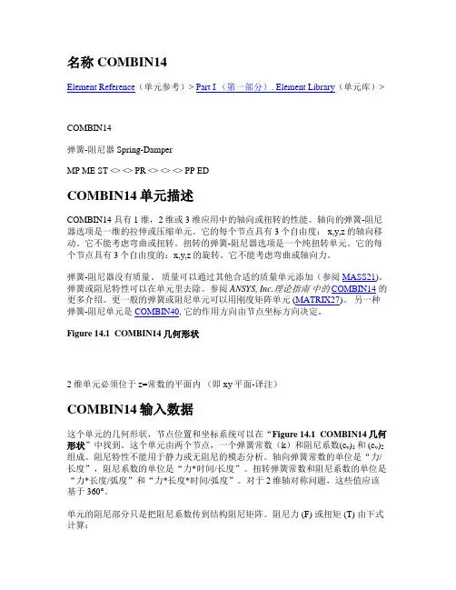
Figure 14.1 COMBIN14几何形状2 维单元必须位于z=常数的平面内(即xy平面-译注)COMBIN14输入数据这个单元的几何形状,节点位置和坐标系统可以在“Figure 14.1 COMBIN14几何形状”中找到。
这个单元由两个节点,一个弹簧常数(k)和阻尼系数(c v)1 和 (c v)2组成。
阻尼特性不能用于静力或无阻尼的模态分析。
轴向弹簧常数的单位是“力/长度”,阻尼系数的单位是“力*时间/长度”。
扭转弹簧常数和阻尼系数的单位是“力*长度/弧度”和“力*长度*时间/弧度”。
对于2维轴对称问题,这些值应该基于360°。
单元的阻尼部分只是把阻尼系数传到结构阻尼矩阵。
阻尼力 (F) 或扭矩 (T) 由下式计算:F x = - c v du x/dt or Tθ = - c v d θ/dt这里 c v是阻尼系数,由c v = (c v)1 + (c v)2v式确定。
Victron Energy 数据通信协议选择指南说明书

IntroductionMany of our customers integrate our products into their own systems, using data communication protocols. There are several options to establish data communication. The purpose of this document is to explain the different options, and help you choose one.Communicating to a complete system? Use Modbus-TCPRather than going for direct communication with Inverters, battery monitors or Solar chargers, consider using ModbusTCP. This has two advantages:1.ModbusTCP is easier than most other protocols2.Retrieve precalculated system, as available on the Color Control GXLooking for internet related protocols? Use the JSON API or MQTTOnce uploaded to the VRM Portal by a Color Control GX, or another device running our Venus OS, the data can be requested via our VRM JSON API: https:///v2/docsBesides that API, MQTT is also available. More information here: https:///victronenergy/dbus-mqtt/blob/master/README.mdIntegrating into a Marine NMEA 2000 network? See our integration guide:https:///live/ve.can:nmea-2000:startMore informationAs a developer, make sure to also have a look at these three pages:1.An intro page of Victron Open source related work and pointers to various reading materials:https:///live/open_source:start2.The main wiki page of Venus OS, the OS that runs on our GX devices:https:///victronenergy/venus/wiki3.The Modifications section on our Community Forum. A forum where many developers help each other on ModbusTCP, MQTT, Node-Red,RaspberryPis, Grafana, Serial communication and many other topics.Products with data communicationThe following product lines have a data communication port, with protocol information available for 3rd parties: ArrayProtocol overviewVictron Energy B.V. | De Paal 35 | 1351 JG Almere | The Netherlands General phone: +31 (0)36 535 97 00 | E-mail: Page 2 of 13NMEA2000 Certified productsThis table lists all Victron products that have an NMEA2000 or VE.Can communication port, and the status of NMEA2000 certification. Note that theMake sure to read our NMEA 2000 & MFD integration guide: https:///live/ve.can:nmea-2000:startDetails per protocolVE.Can / NMEA2000Canbus is the preferred protocol for third parties to communicate with our products. Our CANbus protocol is based on the NMEA2000 and J1939 protocols.Further down in this document is a list per product with supported NMEA2000 PGNs. All data and settings that are not covered by the NMEA2000 standard PGNs are available through proprietary PGNs. More information is in the manuals of the Canbus-enabled products on our website, and in the document “VE.Can registers - public.docx”. Look for it on the Whitepapers page on our website.Detailed information on the NMEA2000 PGN’s is available for purchase on the NMEA website (). See the NMEA 2000® Appendix B POWER SUBSET.VE.DirectVE.Direct is a combination of what we used to call the HEX protocol and the BMV text protocol. It combines the advantages of both: in text-mode the products automatically transmit all important parameters every second. To implement code which reads and interprets this data is extremely simple. If more functionality is needed, such as changing settings, one can switch to the HEX protocol. Communication ports on new Victron products will always be either VE.Can or VE.Direct ports. The VE.Direct port is for products where a full Canbus connection adds to much cost. VE.Direct documentation is available on our website. Look for the VE.Direct Protocol document on: /support-and-downloads/whitepapers/. And see also the VE.Direct FAQ: https:///live/vedirect_protocol:faq.Victron Energy B.V. | De Paal 35 | 1351 JG Almere | The Netherlands General phone: +31 (0)36 535 97 00 | E-mail: Page 3 of 13Modbus TCPThe industry standard Modbus TCP is a well-known and open communication protocol, used in many PLCs and SCADA systems. The Victron Color Control GX acts as a Modbus-TCP gateway. Connect it to the Victron products that you want to monitor, and then communicate from your PLC to the Ethernet LAN port on the Color Control GX. It allows reading information, and writing operational parameters, such as Multi on/off and input current limiter settings. Changing configuration settings, such as battery capacity or float or absorption voltages, is not yet possible. Check the Color Control GX Datasheet to find out which products are supported by the Color Control GX.We use the default Modbus TCP port number, which is 502. The unit id, sometimes called ‘slave address’, specifies what product connected to the CCGX needs to be addressed. See the tab ‘Unit ID mapping’ in the Modbus-TCP excel sheet. The register addresses are listed on the first tab of the excel sheet, in column C. There are two data types, uint16 and int16. After receiving the value, divide it by the Scale factor to get the value in the unit as specified in column G.Download the list of registers from our website, look for the CCGX Modbus-TCP register list on /support-and-downloads/whitepapers/.The FAQ page as well as a commenting system to put questions is available on Victron Live: /live/ccgx:modbustcp_faqEthernet LAN switchVE.BusVE.DirectThe shown Multi and BMV are just an example. See Color Control datasheet for all compatible products.Victron Energy B.V. | De Paal 35 | 1351 JG Almere | The Netherlands Page 4 of 13VE.BusVE.Bus is our proprietary protocol used by the Inverters to synchronize their AC outputs. There are VE.Bus communication ports on our Inverters, Multi’s and Quattro’s. The synchronization feature is mission-critical. Direct third-party connections are not allowed. All interfacing has to be done via Modbus TCP (preferred), “VE.Bus to CANbus/NMEA2000 interface”, or via the MK2/MK3:MK2/MK3 ProtocolThe MK2.2 and MK3 provide a galvanically isolated connection to VE.Bus, and it translates the VE.Bus protocol into the “MK2/MK3 Protocol”. The MK2/MK3 Protocol allows reading information, turning the device on and off, changing the current limits and configuring a device. To download the document, look for the ‘Interfacing with VE.Bus products – MK2/MK3 protocol’ on: /support-and-downloads/whitepapers/Note that implementing the MK2/MK3 protocol is a task which is not to be underestimated. It is a complicated protocol, and unless there is a hugecommercial interest, we cannot give any support or help during the implementation(!). Make sure to have a look at Appendix 2 in that document, which is an annotated example for a typical UI.Note that there is no difference in protocol between the MK2 and MK3 interfaces.BMV-60xS Text Protocol (deprecated)All of our BMV-600’s feature a serial communication interface which allows simple access to detailed battery status information. This protocol only allows reading information from the battery monitor. Setting parameters or ‘synchronizing’ the BMV is not possible. Documentation is available on our website, look for the BMV60xS Text protocol: /support-and-downloads/whitepapers/. Note that this Text protocol is now part of the VE.Direct protocol. The successor of the BMV-600, the BMV-700, works with the VE.Direct protocol. See earlier in this document for more information on the VE.Direct protocol. (deprecated) is a proprietary protocol used by some of our control panels. Third party connections are not possible. New products will not be equipped with . They are equipped with VE.Can or VE.Direct instead.VE 9bit RS485 (deprecated)This protocol was used to communicate to our Multi’s and Quattro’s before they had paralleling and three phase capabilities. This protocol is no longer maintained. Documentation is not available.1 The Victron Interface MK2-USB is an MK2.2b with built-in RS232 to USB Converter.2 The Victron interface MK3-USB also has a built-in RS232 to USB Converter. There is no RS232 version of the MK3 available.3 The VE.Bus to VE.Can interface is the same as the VE.Bus to NMEA2000 interface. The only difference is the canbus connection. The VE.Bus to VE.Can interface has two RJ-45 sockets; the other one has the NMEA2000 Micro-c plug.4 The VE.Direct to VE.Can interface is the same as the VE.Direct to NMEA2000 interface. The only difference is the canbus connection. The VE.Direct to VE.Can interface has two RJ-45 sockets; the other one has the NMEA2000 Micro-c plug.5 Data, including historic data, can be accessed via https://. All data is stored in our database. Logs can be downloaded, see chapter “Getting the data from VRM”.Victron Energy B.V. | De Paal 35 | 1351 JG Almere | The Netherlands General phone: +31 (0)36 535 97 00 | E-mail: Page 5 of 13FAQ – GeneralQ1: Do I need an MK2 or MK3 for each product in a system with multiple VE.Bus products in parallel or three-phase? No. Per VE.Bus system you need only one of those interfaces.Q2: Do I need a VE.Bus to NMEA2000 interface for each product in a system with multiple VE.Bus products in parallel or three-phase? No. Per VE.Bus system you need only one of those interfaces.Q3. Why is it not possible that my application directly communicates with the Victron via VE.Bus messages?VE.Bus is our proprietary protocol used by the Inverters to synchronize their AC outputs. It is not possible to connect directly because as soon as other people are on that bus we cannot guarantee the proper working of paralleled and three-phase operations. Note that even in all our own display andcontrol products that talk to VE.Bus, for example the Color Control GX and the VE.Bus to NMEA2000 interface, we have an MK2/MK3 IC. So even at Victron we are not talking directly to VE.Bus.FAQ – Canbus communicationQ10: Which version of J1939 is actually implemented (J1939/11, J1939/15, J1939/14...)?We are using the NMEA2000 protocol, which is based on ISO 11783-3 (Datalink Layer) and ISO 11783-5 (Network management). ISO 11783-3 is virtually identical to the SAE data link layer SAE J1939-21. The network layer (ISO 1183-5) is based on SAE J1939-81. For more information, see also /content/nmea_standards/white_papers.asp . Q11: Is the bus speed 250kbps? Yes, the bus speed is 250kpbsQ12: Is the identifier extended (29-bits)?Yes, the ISO11783 standard defines the use of the extended identifier (29-bits). Q13: Are the data fields always 8 bytes long? Yes, the data fields are always 8 bytes long.Q14: Can you send us the PGN definition?This detailed documentation has to be bought from the NMEA website. You can buy the Power PGN’s at/store/index.asp?show=pdet&pid=322&cid=7. The product name is “NMEA 2000® Appendix B POWER SUBSET PGN (NMEA Network Messages) – Electronic”, USD 500,= for non-members. Note that for the VE.Bus AC messages you need some SAE documentation as well. More information on the used PGN’s is further down below in this document.Q15: Are all the messages broadcasted or do they have to be requested/polled?The important messages (AC status, Battery status, etc.) are broadcasted. Others have to be polled.Q16: Do I need to terminate the canbus?Yes you do. Use one 120Ohm 0,25W 5% resistor at both ends of the canbus. Connect it between CAN-H and CAN-L. Victron Energy sells a set of VE.Can terminators with part number ASS030700000.6 The Victron Global Remote has two communication ports. It can connect to a BMV and a VE.Bus product or system at the same time.7 The Victron Ethernet Remote has only one communication port, it can connect to one device.8Data can be accessed via a local, password secured, website, running on a web server in the Victron Ethernet Remote. Note that only the current values can be accessed. Historic data is not available on the local web server.Victron Energy B.V. | De Paal 35 | 1351 JG Almere | The Netherlands Page 6 of 13Q17: Do I need to power the canbus?That differs per product. Some products power the canbus themselves others don`t. To power the canbus, supply anywhere between 9 and 36Volts to V+ and V-. See also the pin outs below. A small list at the time of writing:Skylla-i Powers the canbus, isolated Skylla-IP44 Powers the canbus, non-isolated Lynx Shunt VE.Can Powers the canbus, isolated Lynx Ion BMS Powers the canbus, isolated Lynx Ion + Shunt Powers the canbus, isolated Lynx Ion Does not power the canbus, depends on the Lynx Shunt VE.Can to power both the VE.Can and the BMS canbus Color Control GX Does not power the canbus, and needs a powered canbus to operate VE.Bus to NMEA2000 interface Does not power the canbus, and needs a powered canbus to operate VE.Bus to VE.Can interface Does not power the canbus, and needs a powered canbus to operate BMV-60xS to NMEA2000 interface Does not power the canbus, and needs a powered canbus to operate VE.Direct to NMEA2000 interface Does not power the canbus, and needs a powered canbus to operate VE.Direct to VE.Can interface Does not power the canbus, and needs a powered canbus to operate BlueSolar MPPT 150/70 Does power the canbus, not isolated. See manual for info on a resistor that is mounted to prevent ground loops.The mentioned 9 to 36Volt is conform the NMEA2000 standards. Most of our products accept an input voltage from 7 to 70VDC, see the datasheets. Q18: What is the difference between NMEA2000 and VE.Can?The only difference is in the physical connection and the isolation: VE.Can NMEA2000 Physical connector RJ-45 Micro-C Isolation Differs per product, see Q17 above and/ordatasheetAlwaysQ19: What is the pin out of VE.Can?The two RJ-45 sockets on each product that has VE.Can are paralleled. Note that we use RJ-45 also for VE.Bus or connections, see the datasheet to make sure that your product has a VE.Can connection.added. The Skylla-i uses only pin 3 and 6 for power delivery. The Lynx Shunt VE.Can, as well as all later products, use pins 1, 2, 3 and 6. Q20: What is the pin out of NMEA-2000? Q21: I do not want to implement the full ACL procedure, what fixed source address shall I use?Address 0xFE is reserved for when you cannot perform an ACL (Address Claim) procedure. You are free to use this address. See also Q24. Q22: What is Victron’s NMEA2000 manufacturer code? It is 358 (0x166)NET-C / V- (see note below) NET-S / V+ (see note below)Victron Energy B.V. | De Paal 35 | 1351 JG Almere | The Netherlands General phone: +31 (0)36 535 97 00 | E-mail: Page 7 of 13Q23: Instances: I have multiple BMV’s (or another canbus product) in the same network, how do I address them?You need to use instances to differentiate between multiple similar products in the same network. There are different types of instances within NMEA2000:Device instanceThe device instance is sent in PGN 0xEE00, ISO Address Claim, as a combined field of Device Instance Lower (ISO ECU Instance) and Device Instance Upper (ISO Function Instance).The Device instance is used by Victron chargers (Skylla-i/-IP44, VE.Can MPPTs) to configure them in the same group and synchronize them.Data instances (Battery Instance, DC Detailed Instance, Switch bank instance, etc.)These instances are embedded in the different PGN’s. All Victron products support changing these instances through a complex write, PGN 0x1ED00, Complex Request Group Function Code 5, write fields.System instanceThe system instance is also sent in PGN 0xEE00, field 8. It is not used. All Victron products do support changing this instance by sending a complex command.Instance conflictsIf you have connected multiple products sending out the same PGN with the same data instance number, you might encounter a data instance conflict. Typically this can be seen on display’s showing an alternating value. E.g. The VE.Direct to NMEA2000 interface and VE.Bus to NMEA2000 interface are both sending out PGN 127508 with Battery instance 0. To solve this issue one of the Battery instances needs to be changed to another (unique) number. We recommend to change the Battery instance of the VE.Bus to NMEA2000 instance to 5.More information about changing instances is here: /documentation/ve.can:changing_nmea2000_instances .Display manufacturersThe display manufacturers may use different types of instances to show data for multiple batteries, inverters or chargers. For more information about MFD integration, please visit https:///live/ve.can:nmea-2000:start .Q24: Do the Victron VE.Can and NMEA2000 products used fixed network address or do they support NMEA address claim ISO 602928? All our products have implemented the address claim procedure. See also Q21.Q25: I want to read the State of Charge (0 to 100%) as calculated by the Multis and Quattros. I do understand that this SOC is only reliable if there are no DC loads or other battery chargers in the system (almost impossible on a boat, but in a self-consumption system this is very possible). And I cannot find the SOC in the PGNs.Correct, the information is in PGN 127506, but transmission of that PGN is disabled by default, because it is not valid in all systems. To enable transmission of this PGN, change the transmission interval. To do this at protocol level, see NMEA2000 documentation, PGN 126208 - NMEA - Request group function (field 1 = 0x00). And then field 3, transmission interval. To do this at PC level, use Actisense NMEA Reader or other PC software that has this functionality.Q26: Which products have a bag of VE.Can RJ-45 terminators included? These products are shipped with two pieces of VE.Can RJ-45 terminators:- Color Control GX - MPPT 150/70 and MPPT 150/85 Solar Charge Controllers - Lynx Ion + Shunt all models - Lynx Ion BMS all models - Lynx Shunt VE.Can - VE.Bus to VE.Can interface - VE.Direct to VE.Can interface - Skylla-i control - CANUSBThese products are shipped without:- Ion Control (not necessary since terminators are included with the Lynx Ion + Shunt) - BMV-60xS to VE.Can interface - VE.Can to NMEA2000 Micro-C male cable - VE.Can resistive tank sensor (not necessary, terminators are included with the CCGX)Note that it will normally not be necessary to purchase the terminators separately.Victron Energy B.V. | De Paal 35 | 1351 JG Almere | The Netherlands Page 8 of 13Canbus PGN overview per productUse below tables to see where to find what data. There is a freely available PDF file on the NMEA2000 website that also gives a good overview. Go to /content/nmea_standards/downloads.asp , and then the link called “NMEA2000 Parameter Group Descriptions (Messages) with Field Description”. To get the detailed information in order to decode the PGNs, see Q14 in the FAQs.(field 1) are the same number. Changing one of the instances will change all of the mentioned instances.See the VE.Bus to NMEA2000 interface manual for more details (https:///accessories/ve-bus-to-nmea2000-interface ). Note that the Skylla-i/-IP44 will switch off when there is no mains available. It will therefore also stop sending and responding to Canbus messages.9The AC Input Status PGN 127503 is not present on the Skylla-IP44Victron Energy B.V. | De Paal 35 | 1351 JG Almere | The Netherlands General phone: +31 (0)36 535 97 00 | E-mail: Page 9 of 13The Battery instance for PGNs 127508 can be changed. After you did that, you can still distinguish between the Battery and PV information by looking at the DC detailed status PGN, 127506 0x1F212. It will report the DC Type, field 3, as Battery or Solar Cell. Field 2, DC Instance, equals the Battery instance in the Battery Status PGN for battery and solar information.• Battery instance 0 and DC Instance 0 are the same instance number, only the name is different in the NMEA2000 documentation.• Above table is valid for the latest firmware version of the VE.Direct to NMEA2000 interface cable, v1.06. Previous firmware versions used PGN127502 instead of 127501 to report relay and alarm status.See the manual of the VE.Direct to NMEA2000 Interface for more details (https:///accessories/ve-direct-to-nmea2000-interface ).•Both the Lynx Ion and the Lynx Shunt VE.Can are sending Battery pack voltage and Battery pack current. Distinction can only be made on product id.•Battery instance 0 and DC Instance 0 are the same•One or more 24V 180Ah batteries together in one system are a Battery pack.•One 24V 180Ah battery, consisting of 8 cells is a Battery.Page 10 of 13 Victron Energy B.V. | De Paal 35 | 1351 JG Almere | The NetherlandsVictron Energy B.V. | De Paal 35 | 1351 JG Almere | The Netherlands General phone: +31 (0)36 535 97 00 | E-mail: *********************** Page 11 of 13DEPRECATED: Getting data from VRM with wgetUse the JSON API for this, instead of wget. See: https:///v2/docsDEPRECATED: VRM Juice APIUse the new JSON VRM API, instead of Juice. See https:///v2/docsLinks to interesting productsNote that we have not tested all these products, and they are not affiliated to Victron Energy in any way. We do not take any responsibility. Consider using our own Color Control GX as the Victron to ModbusTCP converter, instead of below products.1.NMEA2000 to Modbus RS485 converter by Offshore Systems (UK) Ltd:/3155.htm2.Converters from NMEA2000 to a variety of protocols, one of them is Modbus:/home/products/NMEA2000_Conveters.asp?frompg=nav14_23.RS232 to Ethernet/LAN Converter. Works well with the BMV Text Protocol. With the MK2/MK3 Protocol it is not very stable. The ATOP SE5001-S2/en/productList2.php?pl1_id=2Victron Energy B.V. | De Paal 35 | 1351 JG Almere | The Netherlands General phone: +31 (0)36 535 97 00 | E-mail: *********************** Page 12 of 13Document HistoryVictron Energy B.V. | De Paal 35 | 1351 JG Almere | The Netherlands General phone: +31 (0)36 535 97 00 | E-mail: *********************** Page 13 of 13。
ARTISAN TECHNOLOGY GROUP 质量用途设备来源说明书
DL205PLC User Manual Volume1of2Manual Number:D2-USER-MNotesDL205 PLC USER MANUALNotesVolume One: Table of Contents . . . . . . . . . . . . . . . . . . . . . . . . . . . . . . . .iVolume Two: Table of Contents . . . . . . . . . . . . . . . . . . . . . . . . . . . . . . .xiChapter 1: Getting Started . . . . . . . . . . . . . . . . . . . . . . . . . . . . . . . . . .1–1 Introduction . . . . . . . . . . . . . . . . . . . . . . . . . . . . . . . . . . . . . . . . . . . . . . . . . . . . . . .1–2 The Purpose of this Manual . . . . . . . . . . . . . . . . . . . . . . . . . . . . . . . . . . . . . . . . . . .1–2 Where to Begin . . . . . . . . . . . . . . . . . . . . . . . . . . . . . . . . . . . . . . . . . . . . . . . . . . . .1–2 Supplemental Manuals . . . . . . . . . . . . . . . . . . . . . . . . . . . . . . . . . . . . . . . . . . . . . .1–2 Technical Support . . . . . . . . . . . . . . . . . . . . . . . . . . . . . . . . . . . . . . . . . . . . . . . . . .1–2 Conventions Used . . . . . . . . . . . . . . . . . . . . . . . . . . . . . . . . . . . . . . . . . . . . . . . . . . .1–3 Key Topics for Each Chapter . . . . . . . . . . . . . . . . . . . . . . . . . . . . . . . . . . . . . . . . . .1–3 DL205 System Components . . . . . . . . . . . . . . . . . . . . . . . . . . . . . . . . . . . . . . . . . . .1–4 CPUs . . . . . . . . . . . . . . . . . . . . . . . . . . . . . . . . . . . . . . . . . . . . . . . . . . . . . . . . . . . .1–4 Bases . . . . . . . . . . . . . . . . . . . . . . . . . . . . . . . . . . . . . . . . . . . . . . . . . . . . . . . . . . . .1–4 I/O Configuration . . . . . . . . . . . . . . . . . . . . . . . . . . . . . . . . . . . . . . . . . . . . . . . . . .1–4 I/O Modules . . . . . . . . . . . . . . . . . . . . . . . . . . . . . . . . . . . . . . . . . . . . . . . . . . . . . .1–4 DL205 System Diagrams . . . . . . . . . . . . . . . . . . . . . . . . . . . . . . . . . . . . . . . . . . . . .1–5 Programming Methods . . . . . . . . . . . . . . . . . . . . . . . . . . . . . . . . . . . . . . . . . . . . . . .1–7 Direct SOFT Programming for Windows. . . . . . . . . . . . . . . . . . . . . . . . . . . . . . . . . . .1–7 Handheld Programmer . . . . . . . . . . . . . . . . . . . . . . . . . . . . . . . . . . . . . . . . . . . . . .1–7 Direct LOGIC™ Part Numbering System . . . . . . . . . . . . . . . . . . . . . . . . . . . . . . . . . .1–8 Quick Start for PLC Validation and Programming . . . . . . . . . . . . . . . . . . . . . . . . .1–10 Steps to Designing a Successful System . . . . . . . . . . . . . . . . . . . . . . . . . . . . . . . .1–13Chapter 2: Installation, Wiring and Specifications . . . . . . . . . . . . . . .2–1 Safety Guidelines . . . . . . . . . . . . . . . . . . . . . . . . . . . . . . . . . . . . . . . . . . . . . . . . . . .2–2Table of ContentsPlan for Safety . . . . . . . . . . . . . . . . . . . . . . . . . . . . . . . . . . . . . . . . . . . . . . . . . . . . .2–2 Three Levels of Protection . . . . . . . . . . . . . . . . . . . . . . . . . . . . . . . . . . . . . . . . . . . .2–3 Emergency Stops . . . . . . . . . . . . . . . . . . . . . . . . . . . . . . . . . . . . . . . . . . . . . . . . . . .2–3 Emergency Power Disconnect . . . . . . . . . . . . . . . . . . . . . . . . . . . . . . . . . . . . . . . . .2–4 Orderly System Shutdown . . . . . . . . . . . . . . . . . . . . . . . . . . . . . . . . . . . . . . . . . . . .2–4 Class 1, Division 2, Approval . . . . . . . . . . . . . . . . . . . . . . . . . . . . . . . . . . . . . . . . . .2–4Mounting Guidelines . . . . . . . . . . . . . . . . . . . . . . . . . . . . . . . . . . . . . . . . . . . . . . . .2–5 Base Dimensions . . . . . . . . . . . . . . . . . . . . . . . . . . . . . . . . . . . . . . . . . . . . . . . . . . .2–5 Panel Mounting and Layout . . . . . . . . . . . . . . . . . . . . . . . . . . . . . . . . . . . . . . . . . . .2–6 Enclosures . . . . . . . . . . . . . . . . . . . . . . . . . . . . . . . . . . . . . . . . . . . . . . . . . . . . . . . .2–7 Environmental Specifications . . . . . . . . . . . . . . . . . . . . . . . . . . . . . . . . . . . . . . . . . .2–8 Power . . . . . . . . . . . . . . . . . . . . . . . . . . . . . . . . . . . . . . . . . . . . . . . . . . . . . . . . . . .2–8 Marine Use . . . . . . . . . . . . . . . . . . . . . . . . . . . . . . . . . . . . . . . . . . . . . . . . . . . . . . .2–9 Agency Approvals . . . . . . . . . . . . . . . . . . . . . . . . . . . . . . . . . . . . . . . . . . . . . . . . . .2–924 VDC Power Bases . . . . . . . . . . . . . . . . . . . . . . . . . . . . . . . . . . . . . . . . . . . . . . .2–9Installing DL205 Bases . . . . . . . . . . . . . . . . . . . . . . . . . . . . . . . . . . . . . . . . . . . . . .2–10 Choosing the Base Type . . . . . . . . . . . . . . . . . . . . . . . . . . . . . . . . . . . . . . . . . . . .2–10 Mounting the Base . . . . . . . . . . . . . . . . . . . . . . . . . . . . . . . . . . . . . . . . . . . . . . . .2–10 Using Mounting Rails . . . . . . . . . . . . . . . . . . . . . . . . . . . . . . . . . . . . . . . . . . . . . . .2–11Installing Components in the Base . . . . . . . . . . . . . . . . . . . . . . . . . . . . . . . . . . . .2–12Base Wiring Guidelines . . . . . . . . . . . . . . . . . . . . . . . . . . . . . . . . . . . . . . . . . . . . . .2–13 Base Wiring . . . . . . . . . . . . . . . . . . . . . . . . . . . . . . . . . . . . . . . . . . . . . . . . . . . . . .2–13I/O Wiring Strategies . . . . . . . . . . . . . . . . . . . . . . . . . . . . . . . . . . . . . . . . . . . . . . .2–14 PLC Isolation Boundaries . . . . . . . . . . . . . . . . . . . . . . . . . . . . . . . . . . . . . . . . . . . .2–14 Powering I/O Circuits with the Auxiliary Supply . . . . . . . . . . . . . . . . . . . . . . . . . . .2–15 Powering I/O Circuits Using Separate Supplies . . . . . . . . . . . . . . . . . . . . . . . . . . .2–16 Sinking / Sourcing Concepts . . . . . . . . . . . . . . . . . . . . . . . . . . . . . . . . . . . . . . . . .2–17 I/O “Common” Terminal Concepts . . . . . . . . . . . . . . . . . . . . . . . . . . . . . . . . . . . .2–18 Connecting DC I/O to “Solid State” Field Devices . . . . . . . . . . . . . . . . . . . . . . . . .2–19 Solid State Input Sensors . . . . . . . . . . . . . . . . . . . . . . . . . . . . . . . . . . . . . . . . . . . .2–19 Solid State Output Loads . . . . . . . . . . . . . . . . . . . . . . . . . . . . . . . . . . . . . . . . . . . .2–19 Relay Output Guidelines . . . . . . . . . . . . . . . . . . . . . . . . . . . . . . . . . . . . . . . . . . . .2–21 Surge Suppression For Inductive Loads . . . . . . . . . . . . . . . . . . . . . . . . . . . . . . . . .2–21I/O Modules Position, Wiring, and Specification . . . . . . . . . . . . . . . . . . . . . . . . . .2–25 Slot Numbering . . . . . . . . . . . . . . . . . . . . . . . . . . . . . . . . . . . . . . . . . . . . . . . . . . .2–25 Module Placement Restrictions . . . . . . . . . . . . . . . . . . . . . . . . . . . . . . . . . . . . . . .2–25Table of ContentsSpecial Placement Considerations for Analog Modules . . . . . . . . . . . . . . . . . . . . .2–26 Discrete Input Module Status Indicators . . . . . . . . . . . . . . . . . . . . . . . . . . . . . . . .2–26 Color Coding of I/O Modules . . . . . . . . . . . . . . . . . . . . . . . . . . . . . . . . . . . . . . . .2–26 Wiring the Different Module Connectors . . . . . . . . . . . . . . . . . . . . . . . . . . . . . . . .2–27 I/O Wiring Checklist . . . . . . . . . . . . . . . . . . . . . . . . . . . . . . . . . . . . . . . . . . . . . . . .2–28D2-08ND3, DC Input . . . . . . . . . . . . . . . . . . . . . . . . . . . . . . . . . . . . . . . . . . . . . . . .2–29D2-16ND3-2, DC Input . . . . . . . . . . . . . . . . . . . . . . . . . . . . . . . . . . . . . . . . . . . . . .2–29D2–32ND3, DC Input . . . . . . . . . . . . . . . . . . . . . . . . . . . . . . . . . . . . . . . . . . . . . . .2–30D2–32ND3–2, DC Input . . . . . . . . . . . . . . . . . . . . . . . . . . . . . . . . . . . . . . . . . . . . .2–31D2-08NA-1, AC Input . . . . . . . . . . . . . . . . . . . . . . . . . . . . . . . . . . . . . . . . . . . . . . .2–32D2-08NA-2, AC Input . . . . . . . . . . . . . . . . . . . . . . . . . . . . . . . . . . . . . . . . . . . . . . .2–33D2-16NA, AC Input . . . . . . . . . . . . . . . . . . . . . . . . . . . . . . . . . . . . . . . . . . . . . . . . .2–34F2-08SIM, Input Simulator . . . . . . . . . . . . . . . . . . . . . . . . . . . . . . . . . . . . . . . . . . .2–34D2-04TD1, DC Output . . . . . . . . . . . . . . . . . . . . . . . . . . . . . . . . . . . . . . . . . . . . . .2–35D2–08TD1, DC Output . . . . . . . . . . . . . . . . . . . . . . . . . . . . . . . . . . . . . . . . . . . . . .2–36D2–08TD2, DC Output . . . . . . . . . . . . . . . . . . . . . . . . . . . . . . . . . . . . . . . . . . . . . .2–36D2–16TD1–2, DC Output . . . . . . . . . . . . . . . . . . . . . . . . . . . . . . . . . . . . . . . . . . . .2–37D2–16TD2–2, DC Output . . . . . . . . . . . . . . . . . . . . . . . . . . . . . . . . . . . . . . . . . . . .2–37F2–16TD1(2)P, DC Output With Fault Protection . . . . . . . . . . . . . . . . . . . . . . . . .2–38F2–16TD1P, DC Output With Fault Protection . . . . . . . . . . . . . . . . . . . . . . . . . . .2–39F2–16TD2P, DC Output with Fault Protection . . . . . . . . . . . . . . . . . . . . . . . . . . . .2–40D2–32TD1, DC Output . . . . . . . . . . . . . . . . . . . . . . . . . . . . . . . . . . . . . . . . . . . . . .2–41D2–32TD2, DC Output . . . . . . . . . . . . . . . . . . . . . . . . . . . . . . . . . . . . . . . . . . . . . .2–41F2–08TA, AC Output . . . . . . . . . . . . . . . . . . . . . . . . . . . . . . . . . . . . . . . . . . . . . . . .2–42D2–08TA, AC Output . . . . . . . . . . . . . . . . . . . . . . . . . . . . . . . . . . . . . . . . . . . . . . .2–42D2–12TA, AC Output . . . . . . . . . . . . . . . . . . . . . . . . . . . . . . . . . . . . . . . . . . . . . . . .2–43D2–04TRS, Relay Output . . . . . . . . . . . . . . . . . . . . . . . . . . . . . . . . . . . . . . . . . . . . .2–44D2–08TR, Relay Output . . . . . . . . . . . . . . . . . . . . . . . . . . . . . . . . . . . . . . . . . . . . . .2–45F2–08TR, Relay Output . . . . . . . . . . . . . . . . . . . . . . . . . . . . . . . . . . . . . . . . . . . . . .2–46F2–08TRS, Relay Output . . . . . . . . . . . . . . . . . . . . . . . . . . . . . . . . . . . . . . . . . . . . .2–47D2–12TR, Relay Output . . . . . . . . . . . . . . . . . . . . . . . . . . . . . . . . . . . . . . . . . . . . . .2–48 D2–08CDR 4 pt., DC Input / 4pt., Relay Output . . . . . . . . . . . . . . . . . . . . . . . . . .2–49 Glossary of Specification Terms . . . . . . . . . . . . . . . . . . . . . . . . . . . . . . . . . . . . . . .2–50Chapter 3: CPU Specifications and Operations . . . . . . . . . . . . . . . . . .3–1 CPU Overview . . . . . . . . . . . . . . . . . . . . . . . . . . . . . . . . . . . . . . . . . . . . . . . . . . . . . .3–2 General CPU Features . . . . . . . . . . . . . . . . . . . . . . . . . . . . . . . . . . . . . . . . . . . . . . .3–2 DL230 CPU Features . . . . . . . . . . . . . . . . . . . . . . . . . . . . . . . . . . . . . . . . . . . . . . . .3–2 DL240 CPU Features . . . . . . . . . . . . . . . . . . . . . . . . . . . . . . . . . . . . . . . . . . . . . . . .3–2 DL250–1 CPU Features . . . . . . . . . . . . . . . . . . . . . . . . . . . . . . . . . . . . . . . . . . . . . .3–3 DL260 CPU Features . . . . . . . . . . . . . . . . . . . . . . . . . . . . . . . . . . . . . . . . . . . . . . . .3–3CPU General Specifications . . . . . . . . . . . . . . . . . . . . . . . . . . . . . . . . . . . . . . . . . . .3–4 CPU Base Electrical Specifications . . . . . . . . . . . . . . . . . . . . . . . . . . . . . . . . . . . . . .3–5 CPU Hardware Setup . . . . . . . . . . . . . . . . . . . . . . . . . . . . . . . . . . . . . . . . . . . . . . . .3–6 Communication Port Pinout Diagrams . . . . . . . . . . . . . . . . . . . . . . . . . . . . . . . . . . .3–6 Port 1 Specifications . . . . . . . . . . . . . . . . . . . . . . . . . . . . . . . . . . . . . . . . . . . . . . . .3–7 Port 2 Specifications . . . . . . . . . . . . . . . . . . . . . . . . . . . . . . . . . . . . . . . . . . . . . . . .3–8 Selecting the Program Storage Media . . . . . . . . . . . . . . . . . . . . . . . . . . . . . . . . . . .3–9 Built-in EEPROM . . . . . . . . . . . . . . . . . . . . . . . . . . . . . . . . . . . . . . . . . . . . . . . . . . .3–9 EEPROM Sizes . . . . . . . . . . . . . . . . . . . . . . . . . . . . . . . . . . . . . . . . . . . . . . . . . . . . .3–9 EEPROM Operations . . . . . . . . . . . . . . . . . . . . . . . . . . . . . . . . . . . . . . . . . . . . . . . .3–9 Installing the CPU . . . . . . . . . . . . . . . . . . . . . . . . . . . . . . . . . . . . . . . . . . . . . . . . .3–10 Connecting the Programming Devices . . . . . . . . . . . . . . . . . . . . . . . . . . . . . . . . .3–10 CPU Setup Information . . . . . . . . . . . . . . . . . . . . . . . . . . . . . . . . . . . . . . . . . . . . .3–11 Status Indicators . . . . . . . . . . . . . . . . . . . . . . . . . . . . . . . . . . . . . . . . . . . . . . . . . .3–12 Mode Switch Functions . . . . . . . . . . . . . . . . . . . . . . . . . . . . . . . . . . . . . . . . . . . . .3–12 Changing Modes in the DL205 PLC . . . . . . . . . . . . . . . . . . . . . . . . . . . . . . . . . . .3–13 Mode of Operation at Power-up . . . . . . . . . . . . . . . . . . . . . . . . . . . . . . . . . . . . . .3–13Using Battery Backup . . . . . . . . . . . . . . . . . . . . . . . . . . . . . . . . . . . . . . . . . . . . . . .3–14 DL230 and DL240 . . . . . . . . . . . . . . . . . . . . . . . . . . . . . . . . . . . . . . . . . . . . . . . . .3–14 DL250-1 and DL260 . . . . . . . . . . . . . . . . . . . . . . . . . . . . . . . . . . . . . . . . . . . . . . .3–14 Battery Backup . . . . . . . . . . . . . . . . . . . . . . . . . . . . . . . . . . . . . . . . . . . . . . . . . . . .3–14 Auxiliary Functions . . . . . . . . . . . . . . . . . . . . . . . . . . . . . . . . . . . . . . . . . . . . . . . . .3–15 Clearing an Existing Program . . . . . . . . . . . . . . . . . . . . . . . . . . . . . . . . . . . . . . . . .3–16 Initializing System Memory . . . . . . . . . . . . . . . . . . . . . . . . . . . . . . . . . . . . . . . . . .3–16Setting the Clock and Calendar . . . . . . . . . . . . . . . . . . . . . . . . . . . . . . . . . . . . . . .3–16 Setting the CPU Network Address . . . . . . . . . . . . . . . . . . . . . . . . . . . . . . . . . . . . .3–17 Setting Retentive Memory Ranges . . . . . . . . . . . . . . . . . . . . . . . . . . . . . . . . . . . . .3–17 Using a Password . . . . . . . . . . . . . . . . . . . . . . . . . . . . . . . . . . . . . . . . . . . . . . . . . .3–18 Setting the Analog Potentiometer Ranges . . . . . . . . . . . . . . . . . . . . . . . . . . . . . . .3–19 CPU Operation . . . . . . . . . . . . . . . . . . . . . . . . . . . . . . . . . . . . . . . . . . . . . . . . . . . .3–21 CPU Operating System . . . . . . . . . . . . . . . . . . . . . . . . . . . . . . . . . . . . . . . . . . . . .3–21 Program Mode Operation . . . . . . . . . . . . . . . . . . . . . . . . . . . . . . . . . . . . . . . . . . .3–22 Run Mode Operation . . . . . . . . . . . . . . . . . . . . . . . . . . . . . . . . . . . . . . . . . . . . . . .3–22 Read Inputs . . . . . . . . . . . . . . . . . . . . . . . . . . . . . . . . . . . . . . . . . . . . . . . . . . . . . .3–23 Read Inputs from Specialty and Remote I/O . . . . . . . . . . . . . . . . . . . . . . . . . . . . .3–23 Service Peripherals and Force I/O . . . . . . . . . . . . . . . . . . . . . . . . . . . . . . . . . . . . . .3–23 CPU Bus Communication . . . . . . . . . . . . . . . . . . . . . . . . . . . . . . . . . . . . . . . . . . .3–24 Update Clock, Special Relays and Special Registers . . . . . . . . . . . . . . . . . . . . . . . .3–24 Solve Application Program . . . . . . . . . . . . . . . . . . . . . . . . . . . . . . . . . . . . . . . . . . .3–25 Solve PID Loop Equations . . . . . . . . . . . . . . . . . . . . . . . . . . . . . . . . . . . . . . . . . . .3–25 Write Outputs . . . . . . . . . . . . . . . . . . . . . . . . . . . . . . . . . . . . . . . . . . . . . . . . . . . .3–25 Write Outputs to Specialty and Remote I/O . . . . . . . . . . . . . . . . . . . . . . . . . . . . . .3–26 Diagnostics . . . . . . . . . . . . . . . . . . . . . . . . . . . . . . . . . . . . . . . . . . . . . . . . . . . . . .3–26 I/O Response Time . . . . . . . . . . . . . . . . . . . . . . . . . . . . . . . . . . . . . . . . . . . . . . . . .3–27 Is Timing Important for Your Application? . . . . . . . . . . . . . . . . . . . . . . . . . . . . . . .3–27 Normal Minimum I/O Response . . . . . . . . . . . . . . . . . . . . . . . . . . . . . . . . . . . . . .3–27 Normal Maximum I/O Response . . . . . . . . . . . . . . . . . . . . . . . . . . . . . . . . . . . . . .3–27 Improving Response Time . . . . . . . . . . . . . . . . . . . . . . . . . . . . . . . . . . . . . . . . . . .3–28 CPU Scan Time Considerations . . . . . . . . . . . . . . . . . . . . . . . . . . . . . . . . . . . . . . .3–29 Initialization Process . . . . . . . . . . . . . . . . . . . . . . . . . . . . . . . . . . . . . . . . . . . . . . . .3–30 Reading Inputs . . . . . . . . . . . . . . . . . . . . . . . . . . . . . . . . . . . . . . . . . . . . . . . . . . . .3–30 Reading Inputs from Specialty I/O . . . . . . . . . . . . . . . . . . . . . . . . . . . . . . . . . . . . .3–31 Service Peripherals . . . . . . . . . . . . . . . . . . . . . . . . . . . . . . . . . . . . . . . . . . . . . . . . .3–31 CPU Bus Communication . . . . . . . . . . . . . . . . . . . . . . . . . . . . . . . . . . . . . . . . . . .3–32 Update Clock/Calendar, Special Relays, Special Registers . . . . . . . . . . . . . . . . . . . .3–32 Writing Outputs . . . . . . . . . . . . . . . . . . . . . . . . . . . . . . . . . . . . . . . . . . . . . . . . . . .3–32 Writing Outputs to Specialty I/O . . . . . . . . . . . . . . . . . . . . . . . . . . . . . . . . . . . . . .3–33 Diagnostics . . . . . . . . . . . . . . . . . . . . . . . . . . . . . . . . . . . . . . . . . . . . . . . . . . . . . .3–33 Application Program Execution . . . . . . . . . . . . . . . . . . . . . . . . . . . . . . . . . . . . . . .3–34 PLC Numbering Systems . . . . . . . . . . . . . . . . . . . . . . . . . . . . . . . . . . . . . . . . . . . . .3–35PLC Resources . . . . . . . . . . . . . . . . . . . . . . . . . . . . . . . . . . . . . . . . . . . . . . . . . . . .3–35 V–Memory . . . . . . . . . . . . . . . . . . . . . . . . . . . . . . . . . . . . . . . . . . . . . . . . . . . . . . .3–36 Binary-Coded Decimal Numbers . . . . . . . . . . . . . . . . . . . . . . . . . . . . . . . . . . . . . .3–36 Hexadecimal Numbers . . . . . . . . . . . . . . . . . . . . . . . . . . . . . . . . . . . . . . . . . . . . . .3–36Memory Map . . . . . . . . . . . . . . . . . . . . . . . . . . . . . . . . . . . . . . . . . . . . . . . . . . . . . .3–37 Octal Numbering System . . . . . . . . . . . . . . . . . . . . . . . . . . . . . . . . . . . . . . . . . . .3–37 Discrete and Word Locations . . . . . . . . . . . . . . . . . . . . . . . . . . . . . . . . . . . . . . . . .3–37 V–Memory Locations for Discrete Memory Areas . . . . . . . . . . . . . . . . . . . . . . . . . .3–37 Input Points (X Data Type) . . . . . . . . . . . . . . . . . . . . . . . . . . . . . . . . . . . . . . . . . .3–38 Output Points (Y Data Type) . . . . . . . . . . . . . . . . . . . . . . . . . . . . . . . . . . . . . . . . .3–38 Control Relays (C Data Type) . . . . . . . . . . . . . . . . . . . . . . . . . . . . . . . . . . . . . . . . .3–38 Timers and Timer Status Bits (T Data type) . . . . . . . . . . . . . . . . . . . . . . . . . . . . . .3–38 Timer Current Values (V Data Type) . . . . . . . . . . . . . . . . . . . . . . . . . . . . . . . . . . . .3–39 Counters and Counter Status Bits (CT Data type) . . . . . . . . . . . . . . . . . . . . . . . . .3–39 Counter Current Values (V Data Type) . . . . . . . . . . . . . . . . . . . . . . . . . . . . . . . . . .3–39 Word Memory (V Data Type) . . . . . . . . . . . . . . . . . . . . . . . . . . . . . . . . . . . . . . . . .3–39 Stages (S Data type) . . . . . . . . . . . . . . . . . . . . . . . . . . . . . . . . . . . . . . . . . . . . . . .3–40 Special Relays (SP Data Type) . . . . . . . . . . . . . . . . . . . . . . . . . . . . . . . . . . . . . . . .3–40 Remote I/O Points (GX Data Type) . . . . . . . . . . . . . . . . . . . . . . . . . . . . . . . . . . . .3–40DL230 System V-memory . . . . . . . . . . . . . . . . . . . . . . . . . . . . . . . . . . . . . . . . . . . .3–41DL240 System V-memory . . . . . . . . . . . . . . . . . . . . . . . . . . . . . . . . . . . . . . . . . . . .3–43DL250–1 System V-memory (DL250 also) . . . . . . . . . . . . . . . . . . . . . . . . . . . . . . .3–46DL260 System V-memory . . . . . . . . . . . . . . . . . . . . . . . . . . . . . . . . . . . . . . . . . . . .3–49DL205 Aliases . . . . . . . . . . . . . . . . . . . . . . . . . . . . . . . . . . . . . . . . . . . . . . . . . . . . .3–52DL230 Memory Map . . . . . . . . . . . . . . . . . . . . . . . . . . . . . . . . . . . . . . . . . . . . . . . .3–53DL240 Memory Map . . . . . . . . . . . . . . . . . . . . . . . . . . . . . . . . . . . . . . . . . . . . . . . .3–54DL250–1 Memory Map (DL250 also) . . . . . . . . . . . . . . . . . . . . . . . . . . . . . . . . . . .3–55DL260 Memory Map . . . . . . . . . . . . . . . . . . . . . . . . . . . . . . . . . . . . . . . . . . . . . . . .3–56X Input/Y Output Bit Map . . . . . . . . . . . . . . . . . . . . . . . . . . . . . . . . . . . . . . . . . . .3–57Control Relay Bit Map . . . . . . . . . . . . . . . . . . . . . . . . . . . . . . . . . . . . . . . . . . . . . . .3–59Stage Control/Status Bit Map . . . . . . . . . . . . . . . . . . . . . . . . . . . . . . . . . . . . . . . .3–63Timer and Counter Status Bit Maps . . . . . . . . . . . . . . . . . . . . . . . . . . . . . . . . . . . .3–65Remote I/O Bit Map . . . . . . . . . . . . . . . . . . . . . . . . . . . . . . . . . . . . . . . . . . . . . . . .3–66Chapter 4: System Design and Configuration . . . . . . . . . . . . . . . . . . .4–1DL205 System Design Strategies . . . . . . . . . . . . . . . . . . . . . . . . . . . . . . . . . . . . . . .4–2 I/O System Configurations . . . . . . . . . . . . . . . . . . . . . . . . . . . . . . . . . . . . . . . . . . . .4–2 Networking Configurations . . . . . . . . . . . . . . . . . . . . . . . . . . . . . . . . . . . . . . . . . . .4–2Module Placement . . . . . . . . . . . . . . . . . . . . . . . . . . . . . . . . . . . . . . . . . . . . . . . . . .4–3 Slot Numbering . . . . . . . . . . . . . . . . . . . . . . . . . . . . . . . . . . . . . . . . . . . . . . . . . . . .4–3 Module Placement Restrictions . . . . . . . . . . . . . . . . . . . . . . . . . . . . . . . . . . . . . . . .4–3 Automatic I/O Configuration . . . . . . . . . . . . . . . . . . . . . . . . . . . . . . . . . . . . . . . . . .4–4 Manual I/O Configuration . . . . . . . . . . . . . . . . . . . . . . . . . . . . . . . . . . . . . . . . . . . .4–4 Removing a Manual Configuration . . . . . . . . . . . . . . . . . . . . . . . . . . . . . . . . . . . . .4–5 Power–On I/O Configuration Check . . . . . . . . . . . . . . . . . . . . . . . . . . . . . . . . . . . .4–5 I/O Points Required for Each Module . . . . . . . . . . . . . . . . . . . . . . . . . . . . . . . . . . . .4–6Calculating the Power Budget . . . . . . . . . . . . . . . . . . . . . . . . . . . . . . . . . . . . . . . . .4–7 Managing your Power Resource . . . . . . . . . . . . . . . . . . . . . . . . . . . . . . . . . . . . . . .4–7 CPU Power Specifications . . . . . . . . . . . . . . . . . . . . . . . . . . . . . . . . . . . . . . . . . . . .4–7 Module Power Requirements . . . . . . . . . . . . . . . . . . . . . . . . . . . . . . . . . . . . . . . . . .4–7 Power Budget Calculation Example . . . . . . . . . . . . . . . . . . . . . . . . . . . . . . . . . . . . .4–9 Power Budget Calculation Worksheet . . . . . . . . . . . . . . . . . . . . . . . . . . . . . . . . . .4–10 Local Expansion I/O . . . . . . . . . . . . . . . . . . . . . . . . . . . . . . . . . . . . . . . . . . . . . . . .4–11 D2–CM Local Expansion Module . . . . . . . . . . . . . . . . . . . . . . . . . . . . . . . . . . . . . .4–11 D2–EM Local Expansion Module . . . . . . . . . . . . . . . . . . . . . . . . . . . . . . . . . . . . . .4–12 D2–EXCBL–1 Local Expansion Cable . . . . . . . . . . . . . . . . . . . . . . . . . . . . . . . . . . .4–12 DL260 Local Expansion System . . . . . . . . . . . . . . . . . . . . . . . . . . . . . . . . . . . . . . .4–13 DL250–1 Local Expansion System . . . . . . . . . . . . . . . . . . . . . . . . . . . . . . . . . . . . .4–14 Expansion Base Output Hold Option . . . . . . . . . . . . . . . . . . . . . . . . . . . . . . . . . . .4–15 Enabling I/O Configuration Check using Direct SOFT . . . . . . . . . . . . . . . . . . . . . . .4–16 Expanding DL205 I/O . . . . . . . . . . . . . . . . . . . . . . . . . . . . . . . . . . . . . . . . . . . . . . .4–17 I/O Expansion Overview . . . . . . . . . . . . . . . . . . . . . . . . . . . . . . . . . . . . . . . . . . . .4–17 Ethernet Remote Master, H2-ERM(-F) . . . . . . . . . . . . . . . . . . . . . . . . . . . . . . . . . .4–17 Ethernet Remote Master Hardware Configuration . . . . . . . . . . . . . . . . . . . . . . . . .4–18 Installing the ERM Module . . . . . . . . . . . . . . . . . . . . . . . . . . . . . . . . . . . . . . . . . . .4–19 Ethernet Base Controller, H2-EBC(100)(-F) . . . . . . . . . . . . . . . . . . . . . . . . . . . . . . .4–22 Install the EBC Module . . . . . . . . . . . . . . . . . . . . . . . . . . . . . . . . . . . . . . . . . . . . .4–23 Set the Module ID . . . . . . . . . . . . . . . . . . . . . . . . . . . . . . . . . . . . . . . . . . . . . . . . .4–23 Insert the EBC Module . . . . . . . . . . . . . . . . . . . . . . . . . . . . . . . . . . . . . . . . . . . . . .4–23 Network Cabling . . . . . . . . . . . . . . . . . . . . . . . . . . . . . . . . . . . . . . . . . . . . . . . . . .4–2410BaseFL Network Cabling . . . . . . . . . . . . . . . . . . . . . . . . . . . . . . . . . . . . . . . . . .4–25 Maximum Cable Length . . . . . . . . . . . . . . . . . . . . . . . . . . . . . . . . . . . . . . . . . . . .4–25 Add a Serial Remote I/O Master/Slave Module . . . . . . . . . . . . . . . . . . . . . . . . . . .4–26 Configuring the CPU’s Remote I/O Channel . . . . . . . . . . . . . . . . . . . . . . . . . . . . .4–27 Configure Remote I/O Slaves . . . . . . . . . . . . . . . . . . . . . . . . . . . . . . . . . . . . . . . . .4–29 Configuring the Remote I/O Table . . . . . . . . . . . . . . . . . . . . . . . . . . . . . . . . . . . . .4–29 Remote I/O Setup Program . . . . . . . . . . . . . . . . . . . . . . . . . . . . . . . . . . . . . . . . . .4–30 Remote I/O Test Program . . . . . . . . . . . . . . . . . . . . . . . . . . . . . . . . . . . . . . . . . . .4–31 Network Connections to Modbus and Direct Net . . . . . . . . . . . . . . . . . . . . . . . . . .4–32 Configuring Port 2 For Direct Net . . . . . . . . . . . . . . . . . . . . . . . . . . . . . . . . . . . . . .4–32 Configuring Port 2 For Modbus RTU . . . . . . . . . . . . . . . . . . . . . . . . . . . . . . . . . . .4–32 Modbus Port Configuration . . . . . . . . . . . . . . . . . . . . . . . . . . . . . . . . . . . . . . . . . .4–33 Direct NET Port Configuration . . . . . . . . . . . . . . . . . . . . . . . . . . . . . . . . . . . . . . . .4–34 Network Slave Operation . . . . . . . . . . . . . . . . . . . . . . . . . . . . . . . . . . . . . . . . . . . .4–35 Modbus Function Codes Supported . . . . . . . . . . . . . . . . . . . . . . . . . . . . . . . . . . .4–35 Determining the Modbus Address . . . . . . . . . . . . . . . . . . . . . . . . . . . . . . . . . . . . .4–35 If Your Host Software Requires the Data Type and Address . . . . . . . . . . . . . . . . . .4–35 If Your Modbus Host Software Requires an Address ONLY . . . . . . . . . . . . . . . . . . .4–38 Example 1: V2100 584/984 Mode . . . . . . . . . . . . . . . . . . . . . . . . . . . . . . . . . . . . .4–40 Example 2: Y20 584/984 Mode . . . . . . . . . . . . . . . . . . . . . . . . . . . . . . . . . . . . . . .4–40 Example 3: T10 Current Value 484 Mode . . . . . . . . . . . . . . . . . . . . . . . . . . . . . . .4–40 Example 4: C54 584/984 Mode . . . . . . . . . . . . . . . . . . . . . . . . . . . . . . . . . . . . . .4–40 Determining the Direct NET Address . . . . . . . . . . . . . . . . . . . . . . . . . . . . . . . . . . . .4–40 Network Master Operation . . . . . . . . . . . . . . . . . . . . . . . . . . . . . . . . . . . . . . . . . .4–41 Communications from a Ladder Program . . . . . . . . . . . . . . . . . . . . . . . . . . . . . . .4–44 Multiple Read and Write Interlocks . . . . . . . . . . . . . . . . . . . . . . . . . . . . . . . . . . . .4–44 Network Modbus RTU Master Operation (DL260 only) . . . . . . . . . . . . . . . . . . . .4–45 Modbus Function Codes Supported . . . . . . . . . . . . . . . . . . . . . . . . . . . . . . . . . . .4–45 Modbus Port Configuration . . . . . . . . . . . . . . . . . . . . . . . . . . . . . . . . . . . . . . . . . .4–46 RS–485 Network (Modbus only) . . . . . . . . . . . . . . . . . . . . . . . . . . . . . . . . . . . . . .4–47 RS–232 Network . . . . . . . . . . . . . . . . . . . . . . . . . . . . . . . . . . . . . . . . . . . . . . . . . .4–47 Modbus Read from Network (MRX) . . . . . . . . . . . . . . . . . . . . . . . . . . . . . . . . . . . .4–48 MRX Slave Memory Address . . . . . . . . . . . . . . . . . . . . . . . . . . . . . . . . . . . . . . . . .4–49 MRX Master Memory Addresses . . . . . . . . . . . . . . . . . . . . . . . . . . . . . . . . . . . . . .4–49 MRX Number of Elements . . . . . . . . . . . . . . . . . . . . . . . . . . . . . . . . . . . . . . . . . . .4–49 MRX Exception Response Buffer . . . . . . . . . . . . . . . . . . . . . . . . . . . . . . . . . . . . . .4–49 Modbus Write to Network (MWX) . . . . . . . . . . . . . . . . . . . . . . . . . . . . . . . . . . . . .4–50。
ARTISAN技术组合购物指南说明书
User's Guidee-mail: ************** GPIB HARDWARE MANUAL FOR USE WITHPCI-GPIB, ISA-GPIB142.6 CPCI-GPIB (12)2.5 PC104-GPIB (11)2.4.2 Windows 3.1 (11)2.4.1 Windows 95 (10)2.4 PCM-GPIB (8)2.3 ISA-GPIB/LC (6)2.2 ISA-GPIB (5)2.1 PCI-GPIB (5)CHAPTER TWO: INSTALLATION ...................31.2.3 Connection Configurations . (2)1.2.2 GPIB Electrical Signal Configuration (1)1.2.1 Talkers, Listeners, and Controllers (1)1.2 GPIB SYSTEM DESCRIPTION (1)1.1 HISTORY (1)CHAPTER ONE: INTRODUCTION ......................Chapter One: INTRODUCTION1.1 HISTORYThe GPIB (General Purpose Interface Bus) has become the worldwide standard for connecting instruments to computers. Invented in the 1960s by Hewlett Packard and originally designated as HPIB, the bus specification was eventually adopted by a wide variety of both instrument and computer manufacturers. The original specification was documented and sanctioned by the Institute of Electrical and Electronic Engineers as IEEE-488.The advent of the inexpensive and powerful personal computer has driven the GPIB market through explosive growth. As GPIB bus usage expanded, there arose the need for some additional capability and standardization, so in 1987, IEEE-488.2 was adopted. IEEE-488.2 was revised/ammended in 1992 and represents the current GPIB specification. The new specification provides some standardization among compliant instruments. These standardization greatly simplifies the job of the GPIB system designer since 488.2 compliant instruments share common programming conventions.1.2 GPIB SYSTEM DESCRIPTION1.2.1 Talker s, Listeners, and ControllersA GPIB device can be a Talker, Listener, and/or Controller. As the name implies a Talker sends data to one or more Listeners, A Listener accepts data from a Talker and a Controller manages the flow of information over the bus. A GPIB Digital Voltmeter is acting as a Listener as its input configurations and ranges are set, and then as a Talker when it actually sends its readings to the computer.The Controller is in charge of all communications over the bus. The Controller’s job is to make sure only one device tries to talk at a time, and make sure the correct Lis-teners are paying attention when the Talker talks. Each GPIB system has a single sys-tem controller. The system controller is ultimately in charge of the bus, and is in control as the bus is powered up. There can be more than one Controller on the bus and the System Controller can pass active control to another controller capable device, though only one can be Controller In Charge at a given time. TheGPIB board is usually designated as the System Controller.1.2.2 GPIB Electrical Signal Configuration1The GPIB is an 8-bit parallel data transfer bus. In addition to the 8 data bits, the bus carries three handshaking lines and five GPIB specific management and control lines. The remainder of the standard 24 pin GPIB cable is used for the cable shield, signal grounds and returns. The GPIB connector pin-out is shown in the diagram below:Standard GPIB Cable/ConnectorDATA LINESDIO1 through DIO8 are the data transfer bits. Most GPIB systems send 7-bit data and use the eight bit as a parity or disregard it entirely2HANDSHAKING LINESThere are three handshaking lines that control the data transfer between devices.NRFD (Not Ready For Data): this bit is used to indicate the readiness (or lack thereof) of a device to accept dataDAV (Data Valid): bit is used to indicate to receiving devices that data has been placed on the bus and is available to read.NDAC (Not Data Accepted): is asserted by the receiving device to indicate that data has been read and may now be removed from the bus.SYSTEM MANAGEMENT LINESATN (Attention): is used by the controller to specify how data on the DIO lines is interpreted and which devices must respond to the dataIFC (Interface Clear): is used by the system controller to place the entire system in a known quiescent (Cleared) state and to assert itself as Controller In Charge (CIC).SRQ (Service Request): is used by a device on the bus to indicate the need for atten-tion and requests an interrupt of the current event sequence.REN (Remote Enable): is used by the controller in conjunction with other messages to place a device on the bus into either remote or local modeEOI (End or Identify): Is used by Talkers to indicate the end of a message string, or is used by the Controller to command a polling sequence.1.2.3 Connection ConfigurationsThe GPIB specification is quite definitive regarding the number of devices and cable lengths allowed in a GPIB system. There can be no more than 15 devices on a single contiguous GPIB bus. Larger systems are possible by installing additional GPIB inter-face boards in your computerThe maximum, total length of all cables on a single GPIB system is 20 meters. In addition, cable length between consecutive devices may be no greater than 4 meters, and average cable length must be 2 meters or less. Stated another way, the total cable length (in meters) in the system may not be longer than 2 times the number of devices (up to 20 meters). Longer length systems are possible, but only with the use of a GPIB extender card.In addition to the above rules, at least two thirds of all devices on the bus should be powered on for proper operation.3Keeping the above constraints in mind, there is no limitation on the actual connection scheme used to connect the GPIB devices together. Star, Linear or any combination of both may be used. These are shown in the following diagrams.4,QVWUXPHQW &,QVWUXPHQW ',QVWUXPHQW $,QVWUXPHQW %Linear C onnectionC onfiguration ,QVWUXPHQW ',QVWUXPHQW &,QVWUXPHQW (,QVWUXPHQW $,QVWUXPHQW %S tar C onnectionC onfigurationChapter Two: INSTALLATION The following sections describe the hardware installation procedure for GPIB boards. After hardware installation, please refer to your GPIB software installation guide for additional setup and operation details.2.1 PCI-GPIBThe PCI-GPIB board is completely plug and play. To install this board into your sys-tem follow the simple steps shown below.1. Turn your computer off2. Open your computer case3. Insert the PCI-GPIB into any available PCI slot4. Put your computer’s case back on.5. Turn your computer back on, and follow the instructionsin the GPIB software manual you received with your board.52.2 ISA-GPIBThe only hardware configuration required prior to installing the ISA-GPIB/LC is set-ting the board’s Base Address switch. The location of the Base Address switch is shown in the photograph above, while the switch itself is shown in the diagram on the following page.Most computers will have Base Address 300 Hex (768 decimal) free and the default setting of the board is 300 Hex. If there is already a board in your system using address 300 HEX (768 Decimal), you will have to change the board’s base address prior to installing it in your computer. Other typically free addresses include 310 Hex and 330 Hex.6The following diagram shows the base address in its default 300 Hex setting.987 6 5 4S V65LThe address values corresponding to each of the switches are shown in the following table.Hex Dec.Switch Value Value Default9 200 512 up (200 Hex)8 100 256 up (100 Hex)7 80 128 down (0 Hex)6 40 64 down (0 Hex)5 20 32 down (0 Hex)4 10 16 down (0 Hex)-----------------total 300 HexNote: On this base address switch, Up is on, Down is off. This con-figuration is the opposite of most ISA baseddata acquisition boards.72.3 ISA-GPIB/LCThe following diagram shows the base address in its default 300 Hex setting.987654S V65LThe address values corresponding to each of the switches are shown in the following table.Hex Dec.Switch Value Value Default9200512up (200 Hex)8100256up (100 Hex)7 80128down (0 Hex)6 40 64down (0 Hex)5 20 32down (0 Hex)4 10 16down (0 Hex)-----------------total300 HexNote: On this base address switch, Up is on, Down is off. This con-figuration is the opposite of most ISA based data acquisitionboards.92.4 PCM-GPIBThe installation procedure is different for Windows 95 and DOS/Windows 3.1. These procedures are described below:10:LQGRZVThe PCM-GPIB board is completely plug and play. There are no switches or jumpers to set prior to installation in your computer. Simply follow the steps shown below to install you PCM-GPIB hardware. Once your hardware is installed, please refer to the GPIB-488.2 software manual.1. Start Windows 952. Insert the card into a free PC Card/PCMCIA slot. You do not have toturn the computer off. The system is designed for power on installation.3. Windows 95 will automatically detect the card and depending on theversion of Windows 95 you have, you will either see a New HardwareFound dialog box or a Update Device Driver Wizard box.4. Insert PCM-GPIB Disk 1 into your A drive and follow the instructionsprovided by the dialog box/wizard..If no New Hardware Found dialog box appears, check that you computer’s 32-bit PCMCIA drivers are enabled. This can be checked using the following Windows 95 sequence. Start>Settings>Control Panel>System and look in Performance section. It should read 32-bit. If not, enable 32-bit, shut down your computer and try the above procedure again.:LQGRZVMost users are now installing boards on systems with at least Windows 95 operating systems. However, if you wish to install the PCM-GPIB board in a machine running Windows 3.1 and/or DOS, you will need to use the DOS based Card & Socket serv-ices routine. This is included with most newer computers. However, if you need to purchase these routines, they are available as part number PCM-C&SS from Com-puterBoards for a nominal price. To run the C&SS installation routines, place the PCM-C&SS disk in drive a:, from your boot drive (usually C:) type A:Install and hit enter. Then simply follow the instructions on your screen.The PCM-GPIB hardware is completely plug and play. There are no switches or jumpers to set prior to installation in your computer. Once your hardware is installed, please refer to the GPIB-488.2 software manual.112.5 PC104-GPIBThe only hardware configuration required prior to installing the ISA-GPIB/LC is set-ting the board’s Base Address switch. The location of the Base Address switch is shown in the photograph above, while the switch itself is shown in the diagram on the following page.Most computers will have Base Address 300 Hex (768 decimal) free and the default setting of the board is 300 Hex. If there is already a board in your system using address 300 HEX (768 Decimal), you will have to change the board’s base address prior to installing it in your computer. Other typically free addresses include 310 Hex and 330 Hex.12The following diagram shows the base address in its default 300 Hex setting.987654S V65LThe address values corresponding to each of the switches are shown in the following table.Hex Dec.Switch Value Value Default9200512up (200 Hex)8100256up (100 Hex)7 80128down (0 Hex)6 40 64down (0 Hex)5 20 32down (0 Hex)4 10 16down (0 Hex)-----------------total300 HexNote: On this base address switch, Up is on, Down is off. This con-figuration is the opposite of most PC104 based data acquisitionboards.132.6 CPCI-GPIBThe CPCI-GPIB board is completely plug and play. To install this board install this board into you system follow the simple steps shown below.1. Turn your computer off2. Open your computer front panel (if enclosed)3. Insert the CPCI-GPIB into any available 3U CPCI slot4. Put your computer’s case back on (optional).5. Turn your computer back on, and follow the instructionsin the GPIB software manual you received with your board.14EC Declaration of ConformityDescriptionPart Number Computer to GPIB interface Computer to GPIB interface Computer to GPIB interface Computer to GPIB interface Computer to GPIB interface Computer to GPIB interface ISA-GPIBISA-GPIB/LCPCI-GPIBPC104-GPIBPCM-GPIB CPCI-GPIBto which this declaration relates, meets the essential requirements, is in conformitywith, and CE marking has been applied according to the relevant EC Directives listedbelow using the relevant section of the following EC standards and other normativedocuments:EU EMC Directive 89/336/EEC : Essential requirements relating to electromagneticcompatibility.EU 55022 Class B : Limits and methods of measurements of radio interferencecharacteristics of information technology equipment.EN 50082-1: EC generic immunity requirements.IEC 801-2: Electrostatic discharge requirements for industrial process measurementand control equipment.IEC 801-3: Radiated electromagnetic field requirements for industrial processmeasurements and control equipment.IEC 801-4: Electrically fast transients for industrial process measurement and controlequipment.Carl Haapaoja, Director of Quality Assurance。
XXXXXXXXXXXXXXXXXXXX系统操作手册【模板】
XXXXXXXXXXXXXXXXXXXX系统操作手册-------TRICONEX目录1.TriStation 1131操作手册 (2)2.Triconex SOE 操作手册 (8)3.Enhanced Diagnostic 诊断软件操作手册 (11)4.DDE Server 操作手册 (15)5.InTouth 操作手册 (18)6.特殊操作注释 (24)第一章TriStation 1131操作手册1.1 1131编程变量前缀,所有程序均按照此前缀编写逻辑1.2 登录到1131软件,打开软件界面在程序文件夹中双击图标,弹出:输入用户名(MANAGER)和密码(password)打开程序,在左面的菜单栏中如图所示:选择控制器画面,然后选择控制器双击连接,选择单击控制器连接,以使软件与控制器连接。
1.3 进入逻辑程序选择OK,双击右侧打开程序要看其中某一个逻辑可以双击打开需要选择的逻辑,然后选择连接并打开。
每个逻辑的都注有说明用来解释该逻辑功能,如图所示:1.4 进入逻辑块在进入到需要的程序块后,可以通过以下方式进入到每一逻辑块的每一页程序,选择可以直接看该逻辑中的某一页程序选择参数设置A组,然后按进入程序(或双击)。
1.5 在线情况修改报警值,连锁值在这个逻辑中可以修改报警联锁值,a. 双击修改报警值位号b. 选择“Disable”,然后写入新的报警联锁值(555),然后按Confirm , 新联锁值改为,然后选择Enable,修改结束。
1.6 在程序中查找逻辑中位号a. 如果不知道变量在具体哪个程序中,可以在程序文件中进行完全搜索:选择菜单栏上的,选择然后输入位号,然后点Find,搜索后,如下图:发现要找的LT_26121在程序中,然后在右侧边栏中找到相应程序并双击,如图:,就找到了相应变量。
b. 如果知道变量在具体哪个程序中,可以打开该程序,然后快捷键ctrl+F,如下图:然后选择Find First查找到第一个位置,然后选择Find Next向后查找,直到全部搜索结束。
什么是PLC软元件
什么是PLC软元件软元件是plc内部具有一定功能的器件,这些器件由电子电路和寄存器及存储器单元等组成,主要包括以下器件。
1)输入继电器(I)输入继电器一般有一个PLC的输入端子与之对应,它用于接收外部开关信号。
外部的开关信号闭合,则输入继电器的线圈得电,在程序中其常开触点闭合,常闭触点断开。
2)输出继电器(Q)输出继电器一般有一个PLC的输出端子与之对应。
当通过程序使输出继电器线圈得电时,PLC上的输出端开关闭合,它可以作为控制外部负载的开关信号,同时在程序中其常开触点闭合,常闭触点断开。
3)通用辅助继电器(M)通用辅助继电器的作用和继电器控制系统中的中间继电器相同,它在PLC中没有输入/输出端子与之对应,因此它的触点不能驱动外部负载。
4)特殊继电器(SM)有些辅助继电器具有特殊功能或用来存储系统的状态变量、控制参数和信息,我们称其为特殊继电器。
5)变量存储器(V)变量存储器用来存储变量。
它可以存放程序执行过程中控制逻辑操作的中间结果,也可以使用变量存储器来保存与工序或任务相关的其他数据.6)局部变量存储器(L)局部变量存储器用来存放局部变量。
局部变量与变量存储器所存储的全局变量十分相似,主要区别在于全局变量是全局有效的,而局部变量是局部有效的.7)顺序控制继电器(S)有些PLC中也把顺序控制继电器称为状态器。
顺序控制继电器用在顺序控制或步进控制中.8)定时器定时器是PLC中重要的编程元件,是累计时间增量的内部器件。
9)计数器(C)计数器用来累计输入脉冲的个数,经常用来对产品进行计数或进行特定功能的编程。
10)模拟量输入映像寄存器(AI)、模拟量输出映像寄存器(AQ)模拟量输入电路用以实现模拟量/数字量( A/D)之间的转换,而模拟量输出电路用以实现数字量/模拟量( D/A)之间的转换。
11)高速计数器(HC)一般计数器的计数频率受扫描周期的影响,不能太高,而高速计数器可累计比CPU的扫描速度更快的事件。
- 1、下载文档前请自行甄别文档内容的完整性,平台不提供额外的编辑、内容补充、找答案等附加服务。
- 2、"仅部分预览"的文档,不可在线预览部分如存在完整性等问题,可反馈申请退款(可完整预览的文档不适用该条件!)。
- 3、如文档侵犯您的权益,请联系客服反馈,我们会尽快为您处理(人工客服工作时间:9:00-18:30)。
凝胶中高分子网络的尺寸大小常以交联点之间的平均距离,即平均相邻两交联点之间链段(称有效链)的平均分子量Mc 来表示。
的凝胶。
通常宏观凝胶内部的交联点的分布情况是依据介质类型¾凝胶的特性
最根本的性质是兼具固体和液体的性质。
如具备一定的形状和力
学性质,同时,尤其在高度溶胀的凝胶体系中,溶剂具有很大的扩
散系数。
一般具有生物相容性;
体积相变现象:随溶剂组成、温度、pH值、凝胶中的离子组
成、光、电场等外界条件的变化,凝胶体积发生突然的、大幅度的
变化。
有时也称凝胶的这种变化为相变。
凝胶的性质在很大程度上取决于高分子网络结构、网络与溶剂的
相互作用。
凝胶本身为一个处于非平衡状态的开放性体系。
已经发现凝胶与
外界作用,并能够进行能量、物质和信息的交换,具有作为传感器
和化学反应场所的功能。
并且还具有应答外部环境、改变自身形状
或者状态的特性。
从而可吸附、脱吸附、透过物质,即具有载持、
分离和缓释物质的功能。
Although hydrogels play a key role in the new trends of biotechnology, gel chemistry is not only circumscribed to organic molecules. In
there are many inorganic gels, obviously derived from inorganic
and polysilanes. There is another important branch of gel chemistry, named the sol-gel chemistry
has been widely applied in the glass and ceramic fields, where research Commonly, the sol-gel process consists in the preparation of an inorganic network, working in solution at low temperatures. Such reaction involves three main steps: the formation of a colloidal suspension (called "sol"), the subsequent gelation of the sol in a continuous liquid phase ("gel"), and the removal of the solvent.
A great number of products are made by the sol-gel technology, such as
, porous films, window insulators, superconductors, fillers, and optical, dielectic and electronic coatings. No surprisingly, the sol-gel process has even been applied for making 如果凝胶具有适当的交联度,可以采用通常固体材料的表征方法,如对拉伸强度、断裂伸长率和模量的测定
但是通常情况下,特别是对于交联度很低的样品,最为常见到的表征还是溶胀力(Swelling power, q
d
s
w W
W
q=这里,W
胀时的重量和完全干燥时候的重
量。
凝胶
褐藻酸盐、果酸、魔芋、甘露糖等的水性胶体,通过加入其他的如胶原、明胶等蛋白质都可通过氢键交联形成。