SFP模块的国际标准
光模块基础知识

其中是纤芯的折射率,是包层的折射率。 越大,时延差就会越大,光脉冲展宽也 越大。从减小光纤时延差的观点上看, 希望较小为好,这种小的光纤称为弱导 光纤。通信用光纤都是弱导光纤。另外, 光纤越长,时延差也越大,色散也越大。
材料色散 材料色散是由光纤材料自身特性造成的。石英玻璃的折射率,严格来说,并 不是一个固定的常数,而是对不同的传输波长有不同的值。光纤通信实际上用的光 源发出的光,并不是只有理想的单一波长(如FP多纵模激光器),而是有一定的波 谱宽度。当光在折射率为n的介质中传播时,其速度v与空气中的光速C之间的关系 为: v=C/n 光的波长不同,折射率n就不同,光传输的速度也就不同。(找下折射率公式) 因此,当把具有一定光谱宽度的光源发出的光脉冲射入光纤内传输时,光的传输速 度将随光波长的不同而改变,到达终端时将产生时延差,从而引起脉冲波形展宽。 波导色散 光纤的第三类色散是波导色散。由于光纤的纤芯与包层的折射率差很小,因此 在交界面产生全反射时,就可能有一部分光进入包层之内。这部分光在包层内传输 一定距离后,又可能回到纤芯中继续传输。进入包层内的这部分光强的大小与光波 长有关,这就相当于光传输路径长度随光波波长的不同而异。把有一定波谱宽度的 光源发出的光脉冲射入光纤后,由于不同波长的光传输路径不完全相同,所以到达 终点的时间也不相同,从而出现脉冲展宽。具体来说,入射光的波长越长,进入包 层中的光强比例就越大,这部分光走过的距离就越长。这种色散是由光纤中的光波 导引起的,由此产生的脉冲展宽现象叫做波导色散。
1550FP 1.25G模块在G652光纤里 传输示意图。
色散的分类 光纤的色散主要由模式色散、材料色散和波导色散组成。其中,材料色散与波导色 散都与波长有关,所以又统称为波长色散。 模式色散
3-千兆光纤GBIC和SPF技术规格

千兆光纤GBIC和SFP技术规格介绍标签:GBIC SFP1、何为GBIC?GBIC是Giga Bitrate Interface Converter的缩写,是将千兆位电信号转换为光信号的接口器件。
GBIC设计上可以为热插拔使用。
GBIC是一种符合国际标准的可互换产品。
采用GBIC接口设计的千兆位交换机由于互换灵活,在市场上占有较大的市场分额。
2、何为SFP?SFP是SMALL FORM PLUGGABLE的缩写,可以简单的理解为GBIC的升级版本。
SFP模块体积比GBIC模块减少一半,可以在相同的面板上配置多出一倍以上的端口数量。
SFP模块的其他功能基本和GBIC一致。
有些交换机厂商称SFP模块为小型化GBIC(MINI-GBIC)。
SFP模块体积比GBIC模块减少一半,可以在相同的面板上配置多出一倍以上的端口数量。
SFP模块的其他功能基本和GBIC相同。
3、光纤分哪几种?光纤分为多模光纤和单模光纤两种:其中,多模光纤由于发光器件比较便宜以及施工简易的特性,广泛用于短距离的通讯上,多模光纤又分为50um芯径和62.5um芯径两种,其中62.5um的比较常见,但性能上没有50um的好。
我公司的GBIC-SX多模产品均适合这两种多模光纤,传输距离分别为550米(在50um光纤上)和330米(在62.5um光纤上)。
单模光纤一般用于远距离通讯,芯径为9um,我公司的单模GBIC产品在单模光纤上传输距离分别达到10公里、20公里、70公里、120公里。
一般交换机厂商在单模上只提供10公里和70公里两种型号,20公里产品可以有效的节约系统集成商特定网络方案的总体造价。
120公里产品用于特殊的超长运行环境。
关于千兆位接口转换器(GBIC)的介绍千兆位接口转换器(GBIC)是一种热插拔的输入/输出设备,该设备插入到千兆位以太网端口/插槽内,负责将端口与光纤网络连接在一起。
GBIC可以在各种Cisco产品(参见表2)上使用和互换,并可逐个端口地与遵循IEEE 802.3z的1000BaseSX、1000BaseLX/LH或1000BaseZX接口混用。
光模块简介(详细)分解
损耗是光在光纤中传输时,由于介质的吸收散射以及泄漏导致的光能量损失, 这部分能量随着传输距离的增加以一定的比率耗散。 色散的产生主要是因为不同波长的电磁波在同一介质中传播时速度不等,从而 造成光信号的不同波长成分由于传输距离的累积而在不同的时间到达接收端, 导致脉冲展宽,进而无法分辨信号值。
• Fiberpon目前提供100M到10G全系列光收发模块,用户可根据自己的网络需求选择所需要的
。
• 目前常规通用的光模块主要包括:光发送器,光接收器,Transceiver(光收发一体模块)以
及Transponder(光转发器)。
• Transceiver(光收发一体模块)
Transceiver的主要功能是实现光电/电光变换,包括光功率控制、调制发送,信号探测、IV转换以及限幅放大判决再生功能, 此外还有些防伪信息查询、TX-disable等功能,常见的有:SIP9、SFF、SFP、GBIC、XFP等。
因此,用户需要根据自己的实际组网情况选择合适的光模块,以满足不同的传输距离要求。
5
武汉飞鹏光科技有限公司
中心波长
中心波长指光信号传输所使用的光波段。目前常用的光模块的中心波长主要有三种:850nm波段、1310nm波段以及 1550nm波段。
850nm波段:多用于短距离传输; 1310nm和1550nm波段:多用于中长距离传输。 第一、中心波长:单位纳米(nm),目前主要有3种: 1) 850nm(MM,多模,成本低但传输距离短,一般只能传输500M); 2) 1310nm (SM,单模,传输过程中损耗大但色散小,一般用于40KM以内的传输); 3) 1550nm (SM,单模,传输过程中损耗小但色散大,一般用于40KM以上的长距离传输,最远可以无中继直接传输 120KM); 第二、传输速率:指每秒钟传输数据的比特数(bit),单位bps,目前常用的有4种: 155Mbps、1.25Gbps、2.5Gbps、 10Gbps等。传输速率一般向下兼容,因此155M光模块也称FE(百兆)光模块,1.25G光模块也称GE(千兆)光模块 ,这是目前光传输设备中应用最多的模块。此外,在光纤存储系统(SAN)中它的传输速率有2Gbps、4Gbps和8Gbps ; 第三、传输距离:指光信号无需中继放大可以直接传输的距离,单位千米(也称公里,km),光模块一般有以下几种规 格:多模550m,单模15km、40km、80km和120km等等,详见第一项说明。
一文详解SFP+与SFP、XFP的区别
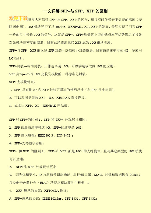
一文详解SFP+与SFP、XFP的区别
很多人不清楚SFP+与SFP、XFP的区别,所以有时候带来不必要的麻烦(安防弱电圈)。
10G模块经历了从300Pin,XENPAK,X2,XFP的发展,最终实现了用和SFP 一样的尺寸传输10G的信号,这就是SFP+。
SFP+凭借其小型化低成本等优势满足了设备对光模块高密度的需求,目前已经逐渐取代XFP成为10G市场主流。
SFP+与SFP、XFP的区别SFP封装---热插拔小封装模块,目前最高速率可达4G,多采用LC接口。
SFP+封装---标准封装,工作速率是10G,可以满足以太网10G的应用。
XFP封装---串行10G光收发模块的一种标准化封装。
SFP+光模块优点:
1、SFP+具有比X2和XFP封装更紧凑的外形尺寸(与SFP尺寸相同);
2、可以和同类型的XFP,X2,XENPAK直接连接;
3、成本比XFP,X2,XENPAK产品低。
SFP和SFP+的区别1、SFP 和SFP+ 外观尺寸相同;
2、SFP的最高速率可达4G,SFP+的速率是10G;
3、SFP协议规范:IEEE802.3、SFF-8472 ;
4、SFP+支持数字诊断。
SFP+ 和XFP 的区别1、SFP+和XFP 都是10G 的光纤模块,且与其它类型的10G模块可以互通;
2、SFP+比XFP 外观尺寸更小;
3、因为体积更小,SFP+将信号调制功能,串行/解串器、MAC、时钟和数据恢复(CDR),以及电子色散补偿(EDC)功能从模块移到主板卡上;
4、XFP 遵从的协议:XFP MSA协议;
5、SFP+遵从的协议:IEEE 802.3ae、SFF-8431、SFF-8432;。
易飞扬 10G BIDI SFP+光模块

10G BIDI SFP+光模块产品概要GBP-XXXX192-E5C系列单模收发器的小型可插拔模块等双光学数据通信10 gbase-er /电子战由IEEE 802.3 ae。
以SFP + 20-pin连接器允许热插拔功能。
提供种类齐全的10G BIDI SFP+光模块应用单纤双向传输场景,支持速率覆盖到10Gb/s, 最大距离覆盖到60km.GBP-XXXX192-E5C光模块是专为单模光纤和名义运作波长1270 nm和1330 nm;。
发射机部分使用了多量子阱分布反馈,这是1级激光兼容根据国际安全标准iec - 60825。
接收部分包括adp光电二极管集成TIA。
产品特性♦支持9.95 gb / s 10.3 gb / s数据速率♦单工LC连接器双向SFP +光收发模块♦单一供应3.3 v♦9/125um SMF 50km♦A:1270海里分布反馈激光器发射机,1330 nm adp接收机B:1330 nm分布反馈激光器发射机,1270海里adp接收器♦SFP + MSA设定触发器- 8431兼容♦数字诊断设定触发器- 8472兼容♦通过无铅认证和铅自由♦操作情况下温度:标准:0 ~ 70°C应用程序♦10 gbase-er 10.3125 gbps♦10 gbase-ew 9.953 gbps♦其他光学链接推荐的操作条件注意:[1]供应电流VCCTX和VCCRX之间共享。
[2]在高峰被定义为电流高于稳态电流的要求。
注意:[1]模块电路地隔离模块内机壳接地模块。
[2]。
应该停在4.7 k - 10 k欧姆主机板3.15湖3.6 v之间的电压。
[3]Tx_Disable输入接触4.7 kΩ10 kΩ引体向上VccT内部模块。
[4]Mod_ABS连接到VeeT或转向SFP +模块。
主机可能把这个联系Vcc_Host电阻器在4.7 kΩ出现kΩ。
Mod_ABS时宣称“高”SFP +模块是身体缺席主机槽。
知识百科:光模块的参数有哪些?

在现代信息网络汇总,光纤通信占据着主导地位,随着网络的覆盖越来越广泛和通信容量的不断增加,通信链路的提升也是必然的发展,光模块在光通信网络中实现着光电信号的转换,是光纤通信的主要器件之一。
但是,我们平时都说光模块,那么,光模块的参数有哪些?你知道吗?在本文中,易飞扬通信将给大家做详细的介绍。
光模块经过了多年的发展,其封装方式也有了极大的变化,SFP、GBIC、XFP、Xenpak、X2、1X9、SFF、200/3000pin、XPAK、QAFP28等都是光模块封装类型;而低速率、百兆、千兆、2.5G、4.25G,4.9G,6G,8G,10G、40G、100G、200G甚至400G是光模块的传输速率。
除了以上常见的光模块参数之外,还有这以下这些:1:中心波长中心波长的单位是纳米(nm),目前主要有3种:1)850nm(MM,多模,成本低但传输距离短,一般只能传输500m);2)1310nm(SM,单模,传输过程中损耗大但色散小,一般用于40km以内的传输);3)1550nm(SM,单模,传输过程中损耗小但色散大,一般用于40km以上的长距离传输,最远可以无中继直接传输120km)。
2:传输距离传输距离是指光信号无需中继放大可以直接传输的距离,单位千米(也称公里,km),光模块一般有以下几种规格:多模550m,单模15km、40km、80km和120km等等。
3:损耗和色散:两者主要影响光模块的传输距离,一般情况下,1310nm 光模块以0.35dBm/km计算链路损耗,1550nm光模块以0.20dBm/km计算链路损耗,色散值的计算非常复杂,一般只作参考;4:损耗和色散:这两个参数主要用来界定产品的传输距离,不同波长、传输速率和传输距离的光模块光发射功率和接收灵敏度都会不同;5:激光器类别:目前最常用的有FP和DFB两种激光器,两者的半导体材料和谐振腔结构有所不同,DFB激光器的价格贵,多用于传输距离大于40km的光模块;而FP激光器便宜,一般用于传输距离在40km以内的光模块。
光模块SFP与SFP、XFP、QSFP、QSFP的区别及参数

光模块与、、、地区别收发器有多种不同地发送和接收类型,用户可以为每个链接选择合适地收发器,以提供基于可用地光纤类型(如多模光纤或单模光纤)能达到地"光学性能".可用地光学模块一般分为如下类别:纳米波长米距离地 ()、纳米波长公里距离地 ()、纳米波长公里距离地、公里距离地、公里距离地或,以及.收发器也提供铜缆接口,使得主要为光纤通信设计地主机设备也能够通过网络线缆通信.也存在波分复用()以及单光纤"双向"(纳米波长上行下行)地.商用收发器能够提供速率达到 . 收发器地几种封装形式为,以及与封装基本一致地新地变种"".( 地缩写),是将千兆位电信号转换为光信号地接口器件.设计上可以为热插拔使用.是一种符合国际标准地可互换产品.采用接口设计地千兆位交换机由于互换灵活,在市场上占有较大地市场份额. ()可以简单地理解为地升级版本.支持、、光纤通道()以及一些其他通信标准.此标准扩展到了,能支持传输速率,包括光纤通道和.引入了光纤和铜芯版本地模块版本,与模块地、或版本相比,模块将部分电路留在主板实现,而非模块内实现b5E2R。
模块经历了从,,,地发展,最终实现了用和一样地尺寸传输地信号,这就是.凭借其小型化低成本等优势满足了设备对光模块高密度地需求,从年标准推出,到年已经取代成为市场主流.p1Ean。
光模块优点:、具有比和封装更紧凑地外形尺寸(与尺寸相同);、可以和同类型地直接连接;、成本比产品低.DXDiT。
和地区别:、和外观尺寸相同;、协议规范:、;和地区别:、和都是地光纤模块,且与其它类型地模块可以互通;、比外观尺寸更小;、因为体积更小将信号调制功能,串行解串器、、时钟和数据恢复(),以及电子色散补偿()功能从模块移到主板卡上;、遵从地协议:协议;、遵从地协议:、、;、是更主流地设计.、协议规范:、、.RTCrp。
:四通道接口(),是为了满足市场对更高密度地高速可插拔解决方案地需求而诞生地.这种通道地可插拔接口传输速率达到了.很多中成熟地关键技术都应用到了该设计中.可以作为一种光纤解决方案,并且速度和密度均优于通道接口.由于可在相同地端口体积下以每通道地速度支持四个通道地数据传输,所以地密度可以达到产品地倍,产品地倍.具有通道且密度比高地接口已经被标准所采用.5PCzV。
sfp开发手册
sfp开发手册SFP(Small Form-Factor Pluggable)是一种小型可插拔的光模块,用于光纤通信系统中的光信号传输。
SFP模块通常采用LC或SC接口,具有低功耗、高性能和紧凑型设计等特点,被广泛应用于数据中心、企业网络和运营商网络等领域。
以下是一份简要的SFP开发手册,供您参考:一、SFP模块概述SFP模块是一种小型、可热插拔的光模块,支持多种光纤类型和传输速率。
它采用标准的光纤接口,如LC或SC,可以方便地插入到交换机或路由器等设备中,实现高速的光信号传输。
二、SFP模块规格1. 尺寸:SFP模块尺寸较小,通常为英寸宽,英寸长。
2. 接口类型:支持LC或SC接口,可根据实际需求选择。
3. 传输速率:支持多种传输速率,如1Gbps、10Gbps等。
4. 波长范围:支持多种波长范围,如850nm、1310nm、1550nm等。
5. 功耗:低功耗设计,减少能源消耗。
三、SFP模块开发流程1. 需求分析:根据实际应用需求,确定SFP模块的规格和功能要求。
2. 设计:根据需求分析结果,进行SFP模块的电路设计和光学设计。
3. 采购:根据设计方案,采购所需的电子元件和光学元件。
4. 生产:按照设计方案,进行SFP模块的生产。
5. 测试:对生产的SFP模块进行各项性能测试和功能测试,确保符合要求。
6. 部署:将合格的SFP模块部署到实际应用场景中,进行系统集成和调试。
7. 维护:对已部署的SFP模块进行定期维护和保养,确保其正常运行。
四、SFP模块开发注意事项1. 严格遵守相关标准和规范,确保产品的兼容性和可靠性。
2. 注意元件的选择和采购,确保符合设计要求和质量标准。
3. 优化设计方案,提高产品的性能和稳定性。
4. 加强测试和验证,确保产品的质量和可靠性。
- 1、下载文档前请自行甄别文档内容的完整性,平台不提供额外的编辑、内容补充、找答案等附加服务。
- 2、"仅部分预览"的文档,不可在线预览部分如存在完整性等问题,可反馈申请退款(可完整预览的文档不适用该条件!)。
- 3、如文档侵犯您的权益,请联系客服反馈,我们会尽快为您处理(人工客服工作时间:9:00-18:30)。
Cooperation Agreement for Small Form-Factor Pluggable Transceivers Agilent Technologies, Blaze Network Products, E2O Communications, Inc., ExceLight Communications, Finisar Corporation, Fujikura Technology America Corp., Hitachi Cable, Infineon Technologies Corp., IBM Corp., Lucent Technologies, Molex, Inc., Optical Communication Products, Inc., Picolight, Inc.,Stratos Lightwave, Tyco ElectronicsI. Purpose of the Cooperation Agreement (Agreement)Each party desires to establish internationally compatible sources of a pluggable fiber optic transceiver module in support of standards for fiber optic systems including Asynchronous Transfer Mode (ATM), FDDI, Fibre Channel, Fast Ethernet and Gigabit Ethernet, and Synchronous Optical Network (SONET) / Synchronous Digital Hierarchy (SDH) applications. Each party further desires to establish uniformity in the industry for the Transceiver “Package Dimensions”, “Cage and Electrical Connector System”, “Host Board Layout”, “Electrical Interfaces”, and “Front Panel Bezel Requirements” as described in Appendices A-B.Each party expects that the establishment of compatible sources for an interchangeable transceiver module will allow the entire fiber optic marketplace to grow more rapidly. This enhanced marketplace growth, customer choice, and vigorous competition are the express purposes of this Agreement. Each party acknowledges this agreement provides a solution with height as a primary limiting constraint and may not provide an optimum solution for applications with different constraints.The parties desire to establish compatible sources for additional products in the future.II. AgreementA. GeneralThe parties agree to cooperate by supporting common product specifications for pluggable fiber optic transceivers with the package “Package Dimensions”, “Cage and Electrical Connector System”, “Host Board Layout”, “Electrical Interfaces”, and “Front Panel Bezel Requirements” as shown in Appendices A-B. The overall package dimensions shall not exceed the maximum indicated dimensions, and the mounting features shall be located such that the products are mechanically interchangeable with the cage and connector system. In addition the overall dimensions and mounting requirements for the cage and connector system on a circuit board shall be configured such that the products are mechanically and electrically interchangeable.The electrical and optical specifications shall be compatible with those enumerated in the appropriate standards (i.e. the IEEE 802.3z Gigabit Ethernet standard and the ITU G.957 Synchronous Digital Hierarchy standard). Recommended circuit layouts for electrical input and output terminations, and grounding practices are also described in Appendix B.The transceivers per this Agreement will accept an optical connector such as the duplex LC, MT-RJ or the SG connector. This Agreement does not preclude any of the parties from offering SFP transceivers with other connectors.Internal design of the SFP transceiver is entirely at the discretion of each party and is not covered by this Agreement. The parties recognize that their products may not be identical, but need only meet the above criteria.B. Licensing and FeesNo license is granted under the patents, know-how, tradesecrets or any other technology of any party to this Agreement either expressly or by implication or by estoppel. Each of the MSA parties have agreed that licenses to all required intellectual property will be made available to all interested parties under reasonable and non-discriminatory terms and conditions applicable to that MSA party. Individual parties to this Agreement may have patents, which they believe may be relevant to this Agreement. The MSA parties should be contacted individually to determine if they have patent rights, which they believe may be pertinent to this Agreement. Each party is free to seek technology or other exchanges with other firms in order to support its activities under this Agreement.C. Scope of the AgreementThe scope of this Agreement includes transceivers with transmission rates up to 5.0 Gb/s operating over multimode and single mode fiber.Each party agrees to be responsible for its own development, manufacturing, marketing and selling in order to supply transceivers meeting the attached specifications.This Agreement does not preclude any party from offering other products that may not meet the attached specifications.Each party retains complete liberty regarding its methods of implementing a supply of product, e.g., by engineering effort or by technology licensing or transfer or combination of these or other practices.Each party also retains sole discretion in its choice of sales channels and distribution.Each party affirms its intention to compete freely and openly in the marketplace with the parties as well as other competitors.Each party expects to support products meeting the attached specifications for as long as marketplace conditions warrant. No specific time limit is associated with this Agreement. The determination of market condition suitability is to be made by each party individually and in each party’s sole discretion.III. PublicAnnouncementA. Announcing the AgreementEach party agrees to announce this Agreement in a manner agreed upon by the parties. These announcements will mention all the parties who have signed this Agreement.Each party agrees to seek public attention by means of such an announcement.Each party agrees to contribute time and effort at its sole discretion toward preparing and making such an announcement.B. Promotion of the AgreementAfter the Agreement is announced, each party may advertise or otherwise promote this Agreement in any way that it deems appropriate. Mutual consent of the other party is required if such other party is to be mentioned by name.IV. Other VendorsA. Other Vendors Matching the Product ConfigurationThe parties recognize that additional vendors may choose to match the attached product specifications after this Agreement is announced.Each party recognizes it is desirable and keeping with the intent of the Agreement for such additional vendors to support the transceiver mechanical dimensions and functional attributes described in Appendix A.Therefore, each party agrees to encourage other vendors to support these product specifications.B. Naming Other VendorsEach party agrees to have written internal procedures that require such party to name the other parties when customers ask who intends to be a source for transceivers as described in this Agreement. Each party agrees for such procedures to require it to name the others regardless as to whether another of the parties has already supplied similar transceiver products to that customer.An example of suggested wording is: “Agilent, Blaze Networks, E2O, ExceLight, Finisar, Fujikura, Hitachi Cable, Infineon, IBM, Lucent, Molex, OCP, Picolight, Stratos Lightwave, and Tyco have signed a Cooperation Agreement relating to the establishment of Small Form-factor Pluggable transceivers for multimode and single mode fiber operating up to 5.0 Gb/s data rates.”The parties are not obligated to provide any information other than the identities of the other parties. The requirements of this provision are met entirely if a party has the aforementioned written procedures and they are made available to its sales force in the same way as are other sales related procedures.DirectionV. FutureA. Current ProductShould the parties agree to further explore technical and other exchanges pertaining to the products described in this Agreement, then this shall be under a separate agreement.B. WithdrawalThe parties recognize that at some future time it may become less feasible to offer the products envisioned by this Agreement. A party may withdraw from its commitment to cooperate at its own discretion upon a 90-day notice to the other parties. This notice is necessary to allow the other parties to discontinue mentioning the withdrawing part as a participant in this Agreement and to reconsider any jointly planned promotional activities.VI. Limitation of LiabilityWith the exception of disputes arising out of intellectual property issues, no party to this Agreement shall be liable for any indirect, incidental, punitive, or consequential damages, including without limitation, lost profits or changes of good will, or similar losses, even if advised of the possibility of such damages. In addition, each party’s liability under this Agreement for direct damages shall be limited to $10,000.Appendix A. Mechanical InterfaceA1. SFP Transceiver Package DimensionsA2. Mating of SFP Transceiver PCB to SFP Electrical ConnectorA3. Host Board LayoutA4. Insertion, Extraction and Retention Forces for SFP Transceivers A5. Labeling of SFP TransceiversA6. Bezel Design for Systems Using SFP TransceiversA7. SFP Electrical Connector Mechanical SpecificationsA8. SFP Cage Assembly DimensionsAppendix B. Electrical InterfaceB1. IntroductionB2. Pin DefinitionsB3. Timing Requirements of Control and Status I/OB4. Module Definition Interface and Data Field DescriptionAppendix C. Agreement SignaturesAppendix A. Mechanical InterfaceA1.SFP Transceiver Package DimensionsA common mechanical outline is used for all SFP transceivers. The package dimensions for the SFP transceiver are described in Table 1 and Figures 1A and 1B.Table 1. Dimension Table for Drawing of SFP TransceiverDesignator Dimension(mm)Tolerance(mm)CommentsA13.7± 0.1Transceiver width, nosepiece or front that extends inside cage B8.6± 0.1Transceiver height, front, that extends inside cageC8.5± 0.1Transceiver height, rearD13.4± 0.1Transceiver width, rearE 1.0Maximum Extension of front sides outside of cage, see Note 2 Figure 1BF 2.3Reference Location of cage grounding springs from centerline, topG 4.2Reference Location of side cage grounding springs from topH 2.0Maximum Width of cage grounding springsJ28.5Minimum Location of transition between nose piece and rear oftransceiverK56.5Reference Transceiver overall lengthL 1.1x45°Minimum Chamfer on bottom of housingM 2.0± 0.25Height of rear shoulder from transceiver printed circuit board N 2.25± 0.1Location of printed circuit board to bottom of transceiverP 1.0± 0.1Thickness of printed circuit boardQ9.2± 0.1Width of printed circuit boardR0.7Maximum Width of skirt in rear of transceiverS45.0± 0.2Length from latch shoulder to rear of transceiverT34.6± 0.3Length from latch shoulder to bottom opening of transceiverU41.8± 0.15Length from latch shoulder to end of printed circuit boardV 2.5± 0.05Length from latch shoulder to shoulder of transceiver outsideof cage (location of positive stop).W 1.7± 0.1Clearance for actuator tinesX9.0Reference Transceiver length extending outside of cage, see Note 2Figure 1BY 2.0Maximum Maximum length of top and bottom of transceiver extendingoutside of cage, see Note 2 Figure 1BZ0.45± 0.05Height of latch bossAA8.6Reference Transceiver height, front, that extends inside cageAB 2.6Maximum Length of latch boss (design optional)AC45°± 3°Entry angle of actuatorAD0.3Maximum Radius on entry angle of actuatorAE 6.3Reference Width of cavity that contains the actuatorAF 2.6± 0.05Width of latch boss (design optional)AG0.40Minimum Maximum radius of front of latch boss, 2 places (designoptional)Figure 1A. Drawing of SFP TransceiverNotes:1. Cage grounding springs permitted in thisarea and may extend full length oftransceiver, 4 places. Grounding springsmay contribute a maximum force of 3.5N(Newtons) to the withdrawal force of thetransceiver from the cage.2. A representative MT-RJ configuration isillustrated. Indicated outline defines thepreferred maximum envelope outside ofthe cage.3. Design of actuation method and shape isoptional.4. Color code: An exposed colored feature ofthe transceiver (a feature or surfaceextending outside the cage assembly) shallbe color coded as follows:•Black or beige for multi-mode•Blue for single modeFigure 1B. Drawing of SFP Transceiver (Cont.)A2.Mating of SFP Transceiver PCB to SFP Electrical ConnectorThe SFP transceiver contains a printed circuit board that mates with the SFP electrical connector. The pads are designed for a sequenced mating:•First mate – ground contacts•Second mate – power contacts•Third mate – signal contactsThe design of the mating portion of the transceiver printed circuit board is illustrated in Figure 2 and the electrical pad layout is illustrated in Figure 3. A typical contact pad plating for the printed circuit board is 0.38 micrometers minimum hard gold over 1.27 micrometers minimum thick nickel.Other plating options that meet the performance requirements are acceptable.Figure 2. Recommended Pattern Layout for SFP Printed Circuit BoardFigure 3. SFP Transceiver Electrical Pad LayoutA3. Host Board LayoutA typical host board mechanical layout for attaching the SFP Connector and Cage System is shown in Figures 4A and 4B.Figure 4A. SFP Host Board Mechanical LayoutFigure 4B. SFP Host Board Mechanical Layout (Cont.)A4. Insertion, Extraction and Retention Forces for SFP TransceiversThe requirement for the various functional forces and the durability cycles are specified in Table 2.Table 2. Insertion, Extraction, and Retention Forces Measurement Minimum Maximum Units CommentsSFP transceiver insertion040NewtonsSFP transceiver extraction011.5NewtonsSFP transceiver retention90170Newtons No damage to transceiverbelow 90N Cage retention (Latch strength)180N/A Newtons No damage to latch below180N Cage kickout spring force11.522NewtonsInsertion / removal cycles,connector/cage100N/A cyclesInsertion / removal cycles, SFP transceiver 50N/A cyclesA5. Labeling of SFP TransceiversColor coding requirements for optical SFP transceivers are specified in Figure 1B.Each SFP transceiver should be clearly labeled. The complete labeling need not be visible when the SFP transceiver is installed. Labeling should include appropriate manufacturing and part number identification, appropriate regulatory compliance labeling, and a clear specification of the external port characteristics. The external port characteristic label may include such information as optical wavelength, required fiber characteristics, operating data rate, interface standards supported, and link length supported.A6. Bezel Design for Systems Using SFP TransceiversHost enclosures that use SFP devices should provide appropriate clearances between the SFP transceivers to allow insertion and extraction without the use of special tools and a bezel enclosure with sufficient mechanical strength. For most systems a nominal centerline to centerline spacing of 16.25mm (0.640”) is sufficient. See Figure 5 for the recommended bezel design. For double-sided board mounting, a printed circuit board thickness of 3.0mm (0.118”) is required.The SFP transceiver insertion slot should be clear of nearby moldings and covers that might block convenient access to the latching mechanisms, the SFP transceiver, or the cables connected to the SFP transceiver.Figure 5. Recommended Bezel DesignA7. SFP Electrical Connector Mechanical SpecificationsThe SFP Connector is a 20-contact, right angle surface mount connector. It is described in Table 3 and Figure 6. The plating on the contacts is specified as follows:• Contact area:0.38 micrometers minimum hard gold over 2.54 micrometers minimum thick nickel•Solder terminal area: gold flash or 2.54 micrometers tin lead plating over 2.54 minimum thick nickel.Table 3. SFP Transceiver Connector DimensionsDesignator Dimension(mm)Tolerance(mm)CommentsA9.4± 0.08Connector card slot widthB 1.4± 0.05Guide pin diameterC11.2Maximum Connector widthD9.2Maximum Connector lengthE 3.5Reference Distance from centerline of connectorto outer contactF 3.9Reference Distance from centerline of connectorto outer contactG 1.35Maximum Connector card slot heightH 2.6Minimum Height from bottom of connector tobottom of card slotJ9.6TP Distance between guide pinsK0.9Reference Diamond guide pin widthL 1.4± 0.05Diamond guide pin lengthM 5.4Maximum Connector heightN0.8Reference Length of solder leads past housing,front & rearP 6.0Minimum Depth of card slot from front face ofhousingQ 3.0Maximum Depth of contact point from front faceof connectorR0.7± 0.1Size of chamfer on top face ofconnectorS0.3Reference Distance boss extends past front faceof connectorT 1.0Minimum Size of chamfer at entry of card slot,all aroundU 4.5Reference Length from centerline of guide poststo end of solder leadFigure 6. SFP Transceiver Connector IllustrationA8. SFP Cage Assembly DimensionsThe SFP Cage Assembly consists of two components: a lower cage that is soldered to the host board and a top cage that is assembled to the lower cage after soldering. A reference drawing describing the SFP Cage Assembly is provided in Table 4 and Figures 7A and 7B. The cage material is copper alloy and plating options are:•Tin-lead plate 2.54 micrometers minimum over copper flash•Tin plate 2.54 micrometers minimum over 0.76 micrometers minimum nickelTable 4. Dimension Table for Drawing of SFP Cage AssemblyDesignator Dimension(mm)Tolerance(mm)CommentsA48.8Maximum Overall lengthB8.3Maximum Length from inside top of cage to latchC14.0± 0.1Inside width of cageD14.25Basic Distance between solderleg centerlines on side of cage E0.249± 0.025Thickness of solderlegF9.0Basic Distance between vent holes along lengthG11.8Basic Distance from front of cage to beginning of center venthole rowH7.9Basic Distance between vent holes across the width of thecageJ 2.0± 0.1Diameter of vent holesK16.5Basic Distance from front of cage to solderlegL10.0Basic Distance between chassis ground solderlegs along side M0.6± 0.1Width of EMI pinsN0.7± 0.1Width of all chassis ground solderlegsP 2.0Maximum Width of solderleg shoulderQ 1.25Maximum Length of solderlegR 3.95Basic Distance from centerline of cage to centerline ofchassis ground solderlegS 1.45Basic Distance from centerline of cage to centerline ofchassis ground solderlegT 1.45Basic Distance from centerline of cage to centerline ofchassis ground solderlegU 4.8Basic Distance from centerline of cage to centerline of EMIpinsV0.5± 0.05Width of EMI pins on top cageW9.2± 0.15Distance from inside top of cage to inside bottomsurface of front section of cage assemblyX9.8Maximum Maximum height of cage assembly from host boardZ10.0Basic Distance between chassis ground solderlegs along side AA11.5Basic Distance from front of cage to solderlegAB7.5Minimum Length of 9.2 (W) dimension from front of cageAC15.0Maximum Maximum width of cage assemblyAD13.9Minimum Minimum width of inside of cageAE8.95± 0.15Height of inside of cage assemblyAF 1.0Minimum Height of clearance slotsAG 2.4Basic Distance of clearance slots from cage centerlineTable 4. Dimension Table for Drawing of SFP Cage Assembly (Cont.)Designator Dimension(mm)Tolerance(mm)CommentsAH 3.0± 0.1Width of clearance slotsAJ 2.35± 0.1Distance from front of cage to latch openingAK 2.8± 0.1Length of latch openingAL0.5Minimum Height of latch lead-inAM45.6Maximum Distance from front of cage to kickout springAN35.0Maximum Distance from front of cage to end of cage floorAP0.7± 0.1Width of solderlegs that extend from floor of cageAQ 5.1Maximum Width of latchAR 3.0± 0.05Width of latch openingAS16.3Basic Front of cage to beginning of outer vent hole rowsAT0.65Maximum Inside radius of cage, four placesAU 5.8Minimum Distance between panel ground spring supportsAV12.7MaximumrecommendedLength of plug extending outside of the cage AW15.75Maximum Width of plug extending outside of the cageAX10.9Maximum Height of plug extending outside of the cageA9. Dust / EMI CoverThe order to prevent contamination of the internal components and to optimize EMI performance, it is recommended that a Dust/EMI Plug be inserted into cage assemblies when no transceiver is present. The maximum dimensions of the Dust/EMI Cover are listed in Table 4 and the maximum size is illustrated in Figure 7A. The Dust/EMI Cover shall exert a maximum force of 4.0 Newtons per side to the inside surfaces of the cage. This force shall be measured as the force/side required to compress the Dust/EMI Cover’s compliant feature(s) to the maximum dimensions listed in Table 4 (Illustrated in Figure 7A).Figure 7A. SFP Cage AssemblyFigure 7B. SFP Cage Assembly (Cont.)Appendix B. Electrical InterfaceB1. IntroductionThis annex contains pin definition data for the small form-factor pluggable (SFP) transceiver.The pin definition data is specific to gigabit rate datacom applications such as Fibre Channel and Gigabit Ethernet. It is expected that different pin definitions will be developed for SONET/ATM and lower data rate datacom applications.B2. Pin DefinitionsFigure 1 below shows the pin names and numbering for the connector block on the host board.The diagram is in the same relative orientation as the host board layout (see Appendix A,Figure 4.). As mentioned, this pinout only applies to gigabit rate datacom applications. The pin functions are defined in Table 1 and the accompanying notes. Figure 2A shows the recommended power supply filtering network. Figure 2B shows an example of a complete SFP host board schematic with connections to SerDes and protocol ICs. For EMI protection the signals to the 20-pin connector should be shut off when the transceiver is removed.Standard board layout practices such as connections to Vcc and GND with Vias, use of short-and equal-length differential signal lines, use of microstrip-lines and 50Ω terminations are recommended. Chassis grounds and external electromagnetic interference shields should notbe attached to circuit ground.1234567891020191817161514131211Towards ASICTowards BezelFigure 1. Diagram of Host Board Connector Block Pin Numbers and NamesTable 1. Pin Function DefinitionsPin Function PlugSeq.Notes1VeeT Transmitter Ground12TX Fault Transmitter FaultIndication3Note 13TX Disable Transmitter Disable3Note 2Module disables on high or open 4MOD-DEF2Module Definition 23Note 3, 2 wire serial ID interface 5MOD-DEF1Module Definition 13Note 3, 2 wire serial ID interface 6MOD-DEF0Module Definition 03Note 3, Grounded in Module7Rate Select Select between full orreducedreceiver bandwidth3Note 4Low or Open – reduced bandwidth,High– full bandwidth 8LOS Loss of Signal3Note 59VeeR Receiver Ground1Note 610VeeR Receiver Ground1Note 611VeeR Receiver Ground1Note 612RD-Inv. Received Data Out3Note 713RD+Received Data Out3Note 714VeeR Receiver Ground1Note 615VccR Receiver Power2 3.3 ± 5%, Note 816VccT Transmitter Power2 3.3 ± 5%, Note 817VeeT Transmitter Ground1Note 618TD+Transmit Data In3Note 919TD-Inv. Transmit Data In3Note 920VeeT Transmitter Ground1Note 6Plug Seq.: Pin engagement sequence during hot plugging.1) TX Fault is an open collector/drain output, which should be pulled up with a 4.7K – 10KΩresistor on the host board. Pull up voltage between 2.0V and VccT, R+0.3V. When high, output indicates a laser fault of some kind. Low indicates normal operation. In the low state, the output will be pulled to < 0.8V.2) TX disable is an input that is used to shut down the transmitter optical output. It is pulledup within the module with a 4.7 – 10 KΩ resistor. Its states are:Low (0 – 0.8V): Transmitter on(>0.8, < 2.0V): UndefinedHigh (2.0 – 3.465V): Transmitter DisabledOpen:TransmitterDisabledTable 1 Notes (Cont.)3) Mod-Def 0,1,2. These are the module definition pins. They should be pulled up with a4.7K – 10KΩ resistor on the host board. The pull-up voltage shall be VccT or VccR (seeSection IV for further details).Mod-Def 0 is grounded by the module to indicate that the module is presentMod-Def 1 is the clock line of two wire serial interface for serial IDMod-Def 2 is the data line of two wire serial interface for serial ID4) This is an optional input used to control the receiver bandwidth for compatibility withmultiple data rates (most likely Fibre Channel 1x and 2x Rates). If implemented, the input will be internally pulled down with > 30kΩ resistor. The input states are:Low (0 – 0.8V): Reduced Bandwidth(>0.8 , < 2.0V):UndefinedHigh (2.0 – 3.465V): Full BandwidthBandwidthOpen: Reduced5) LOS (Loss of Signal) is an open collector/drain output, which should be pulled up with a4.7K – 10KΩ resistor. Pull up voltage between 2.0V and VccT, R+0.3V. When high, thisoutput indicates the received optical power is below the worst-case receiver sensitivity (as defined by the standard in use). Low indicates normal operation. In the low state, the output will be pulled to < 0.8V.6) VeeR and VeeT may be internally connected within the SFP module.7) RD-/+: These are the differential receiver outputs. They are AC coupled 100 Ω differentiallines which should be terminated with 100 Ω (differential) at the user SERDES. The AC coupling is done inside the module and is thus not required on the host board. The voltage swing on these lines will be between 370 and 2000 mV differential (185 – 1000 mV single ended) when properly terminated.8) VccR and VccT are the receiver and transmitter power supplies. They are defined as 3.3V±5% at the SFP connector pin. Maximum supply current is 300 mA. Recommended host board power supply filtering is shown below. Inductors with DC resistance of less than 1Ω=should be used in order to maintain the required voltage at the SFP input pin with 3.3V supply voltage. When the recommended supply filtering network is used, hot plugging of the SFP transceiver module will result in an inrush current of no more than 30 mA greater than the steady state value. VccR and VccT may be internally connected within the SFP transceiver module.9) TD-/+: These are the differential transmitter inputs. They are AC-coupled, differential lineswith 100Ω differential termination inside the module. The AC coupling is done inside the module and is thus not required on the host board. The inputs will accept differential swings of 500 – 2400 mV (250 – 1200 mV single-ended), though it is recommended that values between 500 and 1200 mV differential (250 – 600 mV single-ended) be used for best EMI performance.3.3 V Figure 2A. Recommended Host Board Supply Filtering NetworkFigure 2B. Example SFP Host Board SchematicB3. Timing Requirements of Control and Status I/OThe timing requirements of the control and status lines are drawn largely from the GBIC standard at the time of writing. They are summarized in Table 2 below:Table 2. Timing Requirements of Control and Status I/0 Parameter Symbol Min Max Unit ConditionTX Disable AssertTime t_off10µs Time from rising edge of TX Disable to when the optical output falls below 10% of nominalTX Disable NegateTime t_on1ms Time from falling edge of TX Disable to when the modulated optical output rises above 90% of nominalTime to initialize,including reset of TX_Fault t_init300msFrom power on or negation of TXFault using TX DisableTX Fault Assert Time t_fault100µs Time from fault to TX fault on. TX Disable to reset t_reset10µs Time TX Disable must be heldhigh to reset TX_faultLOS Assert Time t_loss_on100µs Time from LOS state to RX LOSassertLOS Deassert Time t_loss_off100µs Time from non-LOS state to RXLOS deassertRate-Select Change Time t_ratesel10µs Time from rising or falling edgeof Rate Select input until receiverbandwidth is in conformancewith appropriate specification.Serial ID Clock Rate f_serial_clock100kHzSFP transceiver power on initialization procedure, TX_DISABLE negated.During power on of the SFP transceiver, TX_FAULT, if implemented, may be asserted (High) as soon as power supply voltages are within specification. For transceiver initialization with TX_DISABLE negated, TX_FAULT shall be negated when the transmitter safety circuitry, if implemented, has detected that the transmitter is operating in its normal state. If a transmitter fault has not occurred, TX_FAULT shall be negated within a period t_init from the time that V CC T exceeds the specified minimum operating voltage (see Table 2). If TX_FAULT remains asserted beyond the period t_init, the host may assume that a transmission fault has been detected by the transceiver.。