CANopen手册
CANopen用户手册:线性传感器说明书

Content1CANopen 2 1.1EDS Files 2 1.2Support 2 1.3Features 2 1.3.1Basic information 2 1.3.2Basics based on CiA DS-301, V4.2.0 2 1.3.3Basics based on CiA DSP-406, V3.2 3 1.3.4Basics SDO communication 3 1.3.5Basics PDO communication based on CiA 301, V4.2.0 3 1.4Object Library 4 1.4.1Communication Profile Area based on DS 301 V4.2.0 4 1.4.2Device Profile Area 6 1.4.3Manufacturer specific Area 8 1.5Explanations to Object Library 9 1.5.1Object 0x6300 Encoder Cams 9 1.5.2Cam state registers 9 1.5.3Object 0x6400 Work Area 9 1.5.3.1Work Area Supervision 9 1.5.3.2Work Area State 9 1.6LSS / Layer Setting Service 9 1.6.1Configuration of Node-ID 10 1.6.2Configuration of Bit Rate 10 1.6.3Store Configuration Data 11 1.7SDO Services 11 1.7.1SDO Download 11 1.7.2SDO Upload 12 1.7.3SDO Abort 12 1.8Process Data PDO 12 1.8.1PDO Default Setting 12 1.8.2PDO Parameter Setting 12 1.9Error Handling 14 1.9.1Emergency Messages 14 1.10Error Objects 15 1.10.1Manufacturer-specific Status 15 1.11Non-Volatile Storage and Data Restoration 16 1.12Abbreviations 17 1.13Document Changes 171 CANopenThis document reflects the Novotechnik sensor protocol implementation of the standard CANopen protocol.A basic knowledge of the CAN Bus is required for a proper understanding of this document.Most of the definitions made are according to the following CiA Standard specifications.For making use of all the features that these specifications offer, a knowledge about them is absolutely necessary. The sensor supports the CANopen Communication profile DS-301, V4.2.0, Encoder profile DSP-406, V3.2 and Layer Setting Services (LSS) DSP-305, V1.1.2.1.1 EDS FilesFor integration in a common CANopen projecting tool, electronic data sheet (*.eds) files are provided.These files can be downloaded from the Novotechnik Web Site, see Downloads/Operating manualswhere also this document can be found.Electric data sheet see file Product series_CANopen.1.2 SupportIfyouhaveanyquestions,******************************************************.Electronic data sheets or user manuals for previous software versions are available on request.1.3 Features1.3.1 Basic informationVendor ID: 386 = 0x0182 (Novotechnik)Product code: TP1: 04035 = 0x0FC3, TH1: 04042 = 0x0FCA, TM1: 04228 = 0x1084, TF1: 04052 = 0x0FD4 Rev.-No.: f.e 196613 = 0x30005Serial No.: see product label, “YYMMxxxx”1.3.2 Basics based on CiA DS-301, V4.2.01.3.3 Basics based on CiA DSP-406, V3.21.3.4 Basics SDO communication1.3.5 Basics PDO communication based on CiA 301, V4.2.01.4 Object Library1.4.1 Communication Profile Area based on DS 301 V4.2.01) for 1 position marker2) for 2 position markers1.4.2 Device Profile Area* for 1 position marker: default value 0x01** for 1 position marker and product series TM1 / TF1: not available 1.4.3 Manufacturer specific Area1.5 Explanations to Object Library1.5.1 Object 0x6300 Encoder CamsEncoder cams are used to indicate if a position falls below or exceeds a defined value.1.5.2 Cam state registersCam active: the current position value is between the higher and lower cam-limitCam inactive: the current position value is not between the higher and lower cam-limit.The values for low limit (0x631x) and high limit (0x632x) regard the values for preset (0x6010) and measuring steps (0x6005). The value of hysteresis (0x633x) is added in direction of motion.Note: the cam high limit value can have a lower value than the cam low limitA change in cam state causes an EMCY message.The cam state objects (0x6300) are able to be mapped to the TPDOs.1.5.3 Object 0x6400 Work AreaIt is possible for encoders to define a so-called user defined working area.The main purpose for a work area is to get a high-priority information (via EMCY message) when the transducer’s p o-sition leaves its predefined working area.The actual work area information with work area low limit and work area high limit may be stored in object 0x6401 and 0x6402. This way, the area state object (0x6400) may also be used as software limit switches.1.5.3.1 Work Area SupervisionEach work area channel is fixedly linked to a position channel:1.5.3.2 Work Area StateThe values for low limit (0x6401) and high limit (0x6402) regard the values for preset (0x6010) and scaling (0x6501, 0x6502).A change in work area state causes an EMCY message.The work area state objects (0x6400) are able to be mapped to the TPDOs.1.6 LSS / Layer Setting ServiceTo configure the encoder via the LSS(according CiA DS 305) the encoder is handled as a slave, thePLC must have a LSS master functionality.A LSS-message is composed as follows:This applies to the COB-ID:• LSS-Master ⇒ LSS-Slave: 2021 (0x7E5)• LSS-Slave ⇒ LSS-Master: 2020 (0x7E4)LSS can only be used when the encoder is in the stopped status or pre-operational status.The NMT command for setting the encoder in stopped status is:To program via LSS the sensor has to be switched to LSS configuration state.There are two possible ways to do so:• Switch Mode Selective:only the addressed CANopen device is switched to the LSS configuration stateLSS requires data content in the following objects:Example:Vendor-ID (see index 1018/1) 0x0182 LSS-Command 0x40 Product code (see index 1018/2) 0x0BE0 LSS-Command 0x41 Rev.No. (see index 1018/3) 0x10003 LSS-Command 0x42 Serial-No. (see index 1018/4) 0x12345678 LSS-Command 0x43 After receiving the identification objects, the encoder answers with LSS-Command 0x44.• Switch Mode Global: all CANopen devices supporting LSS are switched to the LSS configuration stateWhen the CAN devices are in configuration state the Node-ID and/or the bit rate can be changed. 1.6.1 Configuration of Node-IDThe Node-ID can be programmed with the LSS-Command 0x11N ID: new Node-ID in the range of 1 (127)Err Code: 0: protocol successfully completed / 1: Node-ID out of rangeChange of Node-ID will cause:•Automatic alteration of COB-ID’s for SDO1, EMCY and Heartbeat and TPDOs.•Non-volatile Node-ID storage through …Store Configuration“ in the LSS mode configur ation.1.6.2 Configuration of Bit RateThe Bit Rate can be programmed with LSS-Command 0x13Table Index: 0x07: 20 kBaud0x06: 50 kBaud0x04: 125 kBaud0x03: 250 kBaud0x02: 500 kBaud0x01: 800 kBaud0x00: 1000 kBaudErr Code: 0: protocol successfully completed 1: Bit timing not supportedChange of Bit rate will cause:•The bit rate gets active•Non-volatile CAN bit rate storage through …Store Configuration“ in the LSS mode configuration1.6.3 Store Configuration DataThe LSS configuration data (Node-ID and Bit Rate) are stored to the non-volatile memory of the sen-sor using LSS-Command 0x17Err Code: 0: protocol successfully completed 2: storage media access error1.7 SDO ServicesService Data Objects SDO (according to CiA DS 301) manage the parameter data exchange, e.g. thenon-cyclical execution of the preset function.Parameters of device object library (object index/subindex see chapter 1.4 Object Library) can beread, written or stored by means of SDO.1.7.1 SDO DownloadThe SDO download service is used to configure the parameters.Command 0x2_: 0x22 write command, parameter to encoder0x23 write command, 4 Byte parameter to encoder0x27 write command, 3 Byte parameter to encoder0x2B write command, 2 Byte parameter to encoder0x2F write command, 1 Byte parameter to encoderCommand 0x60: confirmation: parameter receivedNODE-IDUsing writing to object 0x2000, non-volatile storage has to be done by w riting the“save”- signature (0x65766173) on object 0x1010/1 (TP1/TH1) or 0x1010/4 (TF1). These changes will become effective after a communication restart or a power up.Changing the Node-ID will affect all COB-IDs according to the “predefined co nnection s et”.Example: COB-ID TPDO1 = 0x180 + (Node-ID)BIT-RATEUsing writing to object 0x2001; non-volatile storage has to be done by writing the“save”- signature (0x65766173) on ob-ject 0x1010/1 (TP1/TH1) or 0x1010/4 (TF1). These changes will become effective after a communication restart or a power up.1.7.2 SDO UploadThe SDO upload service is used to read the parameters.Command 0x40: read command, parameters from encoderCommand 0x4_: 0x42 read command, parameter to encoder0x43 read command, 4 Byte parameter to encoder0x47 read command, 3 Byte parameter to encoder0x4B read command, 2 Byte parameter to encoder0x4F read command, 1 Byte parameter to encoder1.7.3 SDO AbortIf the SDO download or SDO upload service fails for any reason, the sensor responds with a SDO abort protocol. Abort Code: 0x06090011 subindex does not exist0x06090030 value exceeded0x06020000 object does not exist0x06010001 object is write only0x06010002 object is read only0x06060000 access error0x08000020 data transport error0x08000000 general error0x08000022 wrong state1.8 Process Data PDOProcess Data Objects (according CiA DS 301)manage the process data exchange, f.e the cyclical transmission of the position value. The process data exchange with the CANopen PDOs is a very slim process without protocol overhead.1.8.1 PDO Default Setting2 Transmit PDOs (TPDO) with each max. 8 bytes are provided:0x1800 TPDO1: default: Event-driven with event timer switched off (changeable to synchronous)0x1801 TPDO2: default: synchronous1.8.2 PDO Parameter SettingThe contents of the encoder-specific TPDOs can be configured by variable mapping according to cus-tomer´s requirements. This mapping has to be performed for the encoder as well as for the receiver.The PDO is limited to a maximum size of 8 bytes and 5 mappings per each PDO.Step 1: For changing of mapping, the sensor must be in properational mode and the MSB of PDOCOB-ID has to be set to 1 to deactivate it.Step 2: Clearing entries in mapping table of PDO1 (PDO2) => subindex 0x0 of object 1A00 (1A01)has to be set to 0x00.Step 3: Mapping of objects into PDOExample:A PDO shall be mapped in a way that the "current position", the "current speed" and the "current chiptemperature" are transmitted in one PDO .Mapping #1 “current position”:Mapping #2 “current speed”:Mapping #3: “current chip temperature”.Step 4: Setting entries in mapping table => subindex 0x0 of object 1A00 has to be set to the numbers of mapping en-tries (e.g. 0x03)Step 5: For re-activating the PDO, the MSB of PDO COB-ID has to be set to 0.Note:TPDO1 value for Event Timer must always be higher than the value for Inhibit Time (except for value 0).Failed sending of TPDOs can occur if:•more TPDOs shall be sent than the CANbus may accept due to insufficient CAN bit rate compared to TPDO/Event Timer •excessive bus load or unfavourable setting of COB-ID in the CANopen network prevents TPDOsending•Object 0x1800/5- event timer- is set to 0.1.9 Error HandlingDepending on the type of error occured, the sensor will react accordingly:* according to DS-301, see chapter 1.7 SDO Services** details see chapter 1.9.1 Emergency Messages1.9.1 Emergency MessagesCOB-ID EMCY in object 0x1014.Error-Register in object 0x1001.0x50xx Device Hardware 0x60xx Device Software 0x80xx Monitoring 0x90xx External Error1.10 Error Objects1.10.1 Manufacturer-specific StatusThe object 0x1002 shows the sensor status bit code and is used for internal process control purposes. For servicing this information can be requested via SDO (see chapter 1.7 SDO Services).Bit Definition (if bit value = 1)2 CAN Bus-Off Timer started0-1 NMT Condition of Sensor%11 stopped%10 operational%01 pro-operational%00 initialisation1.11 Non-Volatile Storage and Data RestorationDefault values for all data objects are stored in the non-volatile program memory.Data encryption to the non-volatile memory is only admitted in the pre-operational status.• Storage via LSS:Data must be stored through the LSS Service Configuration/Store while in LSS Configuration Mode (see chapter 1.6 LSS / Layer Setting Service)• Storage via SDO:Object 0x1010:Data is stored in the non-volatile memory during encryption of object 0x1010 with …save“ signature (0x65766173).Object 0x1011:Encryption of object 0x1011 with the sig nature …load“ (0x64616F6C) will upload data from the non-volatile memory. Default settings are being restored (see chapter 1.7 SDO Services).CAUTION: In case of custom programmed parameters like node-ID, averaging, bit rate etc. these will be reset to default in case of the corresponding reset command below (default values see chapter 1.4 Object Library).Object 0x1010 Object 0x1011 Subindex /1AllSubindex /2CommunicationSubindex /3ApplicationSubindex /4ManufacturerCOB-ID SyncGuard Time X XLife Time Factor X XHeartbeat Timer X XTPDO COB-ID D XTPDO Trans Typ X XTPDA Inhibit Time X XTPDO Event Timer X XTPDO Mapping X XNMT Startup X XNode-ID X (TP1/TH1) X (TF1) BitRate X (TP1/TH1) X (TF1) Number of position markers (only TP1 / TH1) XCustom (only TP1 / TH1) X Operating Parameters X XLinear Encoder Measuring Step Settings X XPreset Value X XCAM Enable X XCAM Polarity X XCAM Low Limit X XCAM High Limit X XCAM Hysterese XWork Area Low Limit XWork Area High Limit XX: data saved or restoredD: data set to default value• Delete via SDO Object 0x1010:Additionally to the functionality defined in CiA standard DS-301, CANopen library offers the possibility to delete data inthe non-volatile memory. Del ete process is initiated by sending the signature “kill” (0x6C6C696B) to object 0x1010.• Manufacturing Mode Object 0x1010▪Only TM1 series:If the sensor is out of function and the signature “boot” 0x746F6F62 in object 0x1000 (device type) is active, the sensor is in manufacturing mode. This mode can be left by power off-on or via the operationalcommand.1.12 AbbreviationsCAN Controller Area Networkch channelCOB-ID Communication Object Identifierconst constant parameter, only readableDLC Data Length CodeDS Draft StandardEMCY Emergency ServiceNMT Network-ManagementPDO Process Data ObjectPos Position (value)ro read only, parameter can changerw read/writeRx Novotechnik sensor is consumer of the CAN data frameRTR Remote Transmission RequestSDO Service Data ObjectSYNC Synchronisation messageTPDO Transmit Process Data ObjectTx Novotechnik sensor is producer of the CAN data frame1.13 Document ChangesRevision Changes Date WhoV00 First edition 16.07.14 VM/mm V07 1.2.5 / 1.3.1 object 1801x2: event driven transmission deleted for TPDO2. 1.3.1 objects:TPDO1 and TPDO2: name modified. 1.3.object 1800/2 and 1801/2 comment: synchronous1...240 instead 1...239, TPDO off: 0 added01.04.20 VM/mmV08 1.3.1 object 1010/4 user parameter data instead of manufacturer defined parameters.1.3.1 1010/5 added (Manufacturer data parameter). 1.10. signature kill 6C6C696B insteadof 6B696C6C, comment regarding manufacturing mode added21.01.21 VM/mmV09 1.2 Support added, all further chapter numbers changed1.8.3 Textual modifications 07.09.2117.11.22VM/mm。
CANopen使用手册_V1.01_.

ProNet 伺服驱动器ESTUNCANopen 使用手册修订记录日期修订版本描述作者初稿完成移振华增加第8章移振华1、第3,3,1章“PDO 参数”,修正PDO 默认表格中的COB-ID 和default 值;易健2、增加第9章“通讯例程”——目录——1、概述............................................................................................................................................ . (5)1.1 CAN 主要相关文档 (5)1.2 本手册使用的术语和缩语 (5)1.3 CAN OPEN 概述 (6)2、接线和连接 (7)3、CANOPEN 通讯 (8)3.1 CAN 标识符分配表 (9)3.2 服务数据对象SDO (10)3.3 过程数据对象PDO (12)3.3.1 PDO参数 (14)3.4 SYNC 报文 (20)3.5 E MERGENCY 报文 (21)3.6 HEARTBEAT 报文 (23)3.7网络管理(NMT ) (24)4、单位换算单元(FACTOR GROUP) (26)4.1 单位换算相关参数 (27)4.1.1 position factor (27)4.1.2 velocity factor (29)4.1.3 acceleration factor (30)5、位置控制功能 (31)5.1 位置控制相关参数 (33)6、设备控制 (35)6.1 控制状态机 (35)6.2 设备控制相关参数 (36)6.2.1 controlword (37)6.2.2 statusword (38)6.2.3shutdown_option_code (3)96.2.4disable_operation_option_code (40)6.2.5quick_stop_option_code (4)6.2.6halt_option_code (41)6.2.7fault_reaction_option_code (41)7、控制模式 (42)7.1 控制模式相关参数 (42)7.1.1modes_of_operation (42)7.1.2modes_of_operation_display (43)7.2 回零模式(HOMINGMODE ) (44)7.2.1 回零模式的控制字 (44)7.2.2 回零模式的状态字 (44)7.2.3 回零模式相关参数 (45)7.2.4 回零方法 (47)7.3 速度控制模式(PROFILE VELOCITYMODE ) (49)7.3.1速度模式的控制字 (49)7.3.2 速度模式的状态字 (49)7.3.3 速度控制模式相关参数 (49)7.4 位置控制模式(PROFILE POSITIONMODE ) (53)7.4.1 位置模式的控制字 (53)7.4.2 位置模式的状态字 (53)7.4.3 位置控制相关参数 (54)7.4.4 功能描述 (56)8、CAN 通讯相关参数 (58)9、CANOPEN 通讯例程 (59)9.1 SDO 操作; (59)9.2 PDO 配置 (59)9.3 位置控制例子(P ROFILE P OSITON MODE ) (60)9.4 位置插补控制(I NTERPLATE P OSITION MODE ) (61)9.5 速度控制(P ROFILE V ELOCITY MODE ) (62)9.6 回零 (6)2对象字典表 (64)1、概述1.1 CAN 主要相关文档 CiA DS 301 V 4.01: CiA CANopen Communication Profilefor Industrial Systems - based on CALCiA DSP 402 V 2.0: CiA CANopen Device Profile1.2 本手册使用的术语和缩语CANCiACOBEDSLMTNMTOD参数PDORORWSDO控制器局域网在自动化国际用户和制造商协会中的 CAN。
台达CANopen及A 伺服简易手册

台达产品简易操作手册(一)台达A2伺服马达接头及对应线序(二)台达A2伺服编码器对应接口视图及线序(三)台达A2伺服PR模式参数设定及对应关系表模式设定P1‐01=1DI1=101伺服使能DI2=108相应PR触发DI3=111(POS0)DI4=112(POS1)DI5=113(POS2)DI6=11A(POS3)DI7=11B(POS4)DI8=11C(POS5)一点说明:(1) 当选定一个PR需要运行时,请首先选择,然后在一点延时触发,这样保证能够运行起来,因为触发是脉冲沿有效。
(2) 当需要行走的距离很长时,PR设定的脉冲无法满足要求是,请设定电子齿轮比,相关参数为P1‐44,P1‐45,电子齿轮比是全局参数,一旦设定所有的PR都按照这个比例行走。
(四)CANopen组态介绍1.首先需要安装台达相应的组态软件CANopen Builder,图标如下图2.安装完成如下图3.开始组态步骤一,如下图一图一4.操作如下:请双击右侧窗口的相应的伺服图片,出现如下窗口。
图二4.开始组态步骤三,配置PDO ,如下图三操作如下:窗口1(如下图)的C 部分,打开时可能有默认数据,如有则没有关系可以把它删除掉,然后根据实际需要进行重新配置。
PDO 里面的Rceive PDO Comm…表示伺服接收的内容,即上位机发送给伺服。
PDO 里面的Transmit PDO Comm…表示伺服发出的内容,即上位机从伺服接收。
双击此图标图三5.开始组态步骤四,配置PDO ,如下图四‐1,图四‐2 操作如下:(1)双击窗口1里面的C 部分的一个参数,出现窗口 图四‐1,如下图四‐1在“参数群”部分选择需要的参数,这里必须需要选择P4‐07,利用“下移”按钮进行选择,也可利用“上移”按钮进行移除。
完毕之后确定即可。
(2)双击窗口1里面的C 部分的另外一个参数,同样出现窗口 图四‐2,如下图四‐2 在“参数群”部分选择需要的参数,这里根据需要可以选择P0‐01(伺服报警),利用“下移”按钮进行选择,也可利用“上移”按钮进行移除。
CANopen用户手册V1.30

CTSC-200 CANopen系列产品用户手册深圳市合信自动化技术有限公司发布日期:11/2012手册版本:V1.30版权声明Copyright ©2012深圳市合信自动化技术有限公司版权所有,保留一切权利。
非经本公司书面许可,任何单位和个人不得擅自摘抄、复制本文件内容的部分或全部,并不得以任何形式传播。
、TrustPLC、CoPanel 均为合信自动化技术有限公司的商标。
对于本文件中出现的其它商标,由各自的所有人拥有。
为了便于说明,本文中使用部分软件截图,对于这些软件版权,由各自的所有人拥有。
由于产品版本升级或其它原因,本文件内容会不定期进行更新。
除非另有约定,本文件仅作为使用参考,本文件中的所有陈述、信息和建议不构成任何明示或暗示的担保。
免责声明CTSC-200 CANopen系列产品的安装、操作、维护工作仅限于合格人员执行。
对于使用本资料所引发的任何后果,合信概不负责。
安全注意事项在开始使用之前,请认真阅读用户手册的注意事项,以避免意外事故的发生。
所负责产品安装、操作的人员必须经过严格培训,遵守相关行业的安全规范,严格遵守该手册提供的相关设备注意事项和特殊安全指示,按正确的操作方法进行设备的各项操作。
本手册中,将安全注意事项分为“警告”、“注意”与“提示”三个等级:使用中的注意事项使用中必须有安全电路,保证当外部电源掉电或可编程控制器故障时,可编程控制器的应用系统能安全工作。
在使用的设计中应考虑的方面包括:必须在可编程控制器的外部电路中加设紧急制动电路、保护电路、正反转操作互锁电路和防止机器损坏的位置上限、下限互锁开关。
为确保使设备能安全运行,对重大事故相关的输出信号,请务必设计外部保护电路和安全机构。
可编程控制器的CPU 检测到系统异常可能会导致所有输出关闭;当控制器的部分电路故障时,可能导致其输出不受控制,为保证设备正常运转,需加设合适的外部控制电路。
可编程控制器的继电器、晶体管等输出单元损坏时,会使其输出无法控制为ON 或OFF 状态。
【用户手册】CANOpen主站卡用户手册

左侧设备栏中的绿色箭头表示从站在线。如果需要重新配置从站的 PDO 映射、修改 PDO
通讯参数,可以点击
按钮,打开“配置从站”对话框:
产品用户手册
©2013 Guangzhou ZHIYUAN Electronics Stock Co., Ltd. 5
广州致远电子股份有限公司
CANopen 主站卡用户手册
广州致远电子股份有限公司
CANopen 主站卡用户手册
选择相应的 CANopen 通讯卡和波特率。如果您的网络上大部分从站支持节点守护/心 跳包,您可以设置“从站在线检查方式”为“节点守护”或者“心跳包检测”,这时“从站 在线检查周期”将作为主站轮循周期或从站的心跳包发送周期。
EDS 文件导入后点击工具条上的
如果有从站因为超时而没有搜索到或者您想取消对某个从站的管理时,您还可以点击
/
进行手动添加或删除。
接着点击
,这时会再次弹出以下窗口提示设置系统参数:
产品用户手册
©2013 Guangzhou ZHIYUAN Electronics Stock Co., Ltd. 3
广州致远电子股份有限公司
CANopen 主站卡用户手册
2
闪一下
停止
器件处于停止状态
3
Blinking(闪烁) 预操作
器件处于预操作状态
4
亮
工作
器件处于工作状态
2.3 CANopen 状态
有关 ERR 指示灯与 RUN 指示灯的更详细说明,请查阅 DS303 中的 CANopen 指示灯规 范。例如,RUN 指示灯表示协议正常运行,ERR 指示灯表示协议运行中出现错误。
按钮开始对网络上的从站进行搜索,当获取到
EX250系列CANopen字段总线设备操作手册说明书
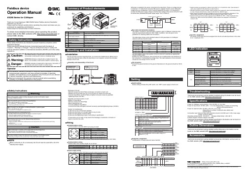
Fieldbus deviceOperation ManualEX250 Series for CANopenMounting and InstallationInstallationThe SI unit does not have mounting holes, so it cannot be installed alone. Make sure to connect the solenoid valve. When an input block is not required, connect the end plate directly to the SI unit.SettingExchange of SI unit•Remove screws from End Plate and release connection of each unit.•Replace old SI unit with new one. (Tie rod does not need to be removed.)•Connect Input Block and End Plate and tighten removed screws by specified tightening torque. (0.6 Nm)Assembly and disconnection of unit Addition of Input Block•Remove screws from End Plate.•Mount attached tie rod.•Connect additional Input Block.•Connect End Plate and tighten removed screws by specified tightening torque. (0.6 Nm)Caution for maintenance(1) Be sure to turn-off all power supplies.(2) Be sure that there is no foreign object in any of units.(3) Be sure that gasket is lined properly.(4) Be sure that tightening torque is according to specification.If these items are not kept, it may lead to the breakage of substrate or intrusion of liquid or dust into the units.TroubleshootingTechnical documentation giving detailed troubleshooting information can be found on the SMC website (URL ).SpecificationsPower for CANopen communication: 18 to 30 VDC, 0.1 A or lessPower for input block: 24 VDC ±20%, 1 A or less (Depending on number of connectingsensors and specifications)Power for solenoid valve: 24 VDC +10%/-5%, 2 A or less(Depending on number of solenoid valve station and specifications)Connection load: Solenoid valve with protection circuit for 24 VDC and 1.5 W or less surgevoltage. (made by SMC)Operating ambient temp: -10 to 50 C Storage ambient temp: -20 to 60 C Pollution degree: Pollution degree 3 (UL508)Technical documentation giving detailed specification information can be found on the SMC website (URL ).Outline DimensionsTechnical documentation giving detailed outline dimensions information can be found on the SMC website (URL ).Assembly and disassembly of the SI unitNOTEWhen conformity to UL is necessary the SI unit must be used with a UL1310Class2 power supply.Thank you for purchasing an SMC EX250 Series Fieldbus device (Hereinafter referred to as "SI unit" ).Please read this manual carefully before operating the product and make sure you understand its capabilities and limitations.Please keep this manual handy for future reference.To obtain more detailed information about operating this product,please refer to the SMC website (URL ) or contact SMC directly.These safety instructions are intended to prevent hazardous situations and/or equipment damage.These instructions indicate the level of potential hazard with the labels of"Caution", " Warning" or "Danger". They are all important notes for safety and must be followed in addition to International standards (ISO/IEC) and other safety regulations.OperatorWiringCommunication wiringSW power is supplied to the sensor connected to the input block. There is a voltage drop up to maximum 1 V inside the SI unit when SW power is supplied. Select a sensor taking this voltage drop into consideration. If 24 V must be supplied to the sensor, it is necessary toincrease the SW power supply voltage so that the input voltage of the sensor will be 24 V with the actual load. (Allowable SW power supply range: 19.2 V to 28.8 V)Bus cable and termination resistorsThe cables, connectors, and termination resistors used in CANopen networks shall meet the requirements defined in ISO 11898. In addition, here are given some guidelines for selecting cables and connectors.The table below shows some standard values for DC parameters for CANopen networks with less than 64 nodes.Switch settingBefore setting of Node-ID by DIP switch, turn “OFF” power supply to the SI unit.Output No. assignmentCombinations of output data and valve manifoldNote: Specifications are subject to change without prior notice and any obligation on the part of the manufacturer.© 2011 SMC Corporation All Rights ReservedtkihabaraMUwXMdhy]Mg_dg_d]MSotokanda]Mvhiyoda_ku]MTokyoMdcd_cced]M±tPt−PhonemM[kdMf_hecj_keglMMMyaxmM[kdMf_helk_hfieUR“Mhttpmbbwwwasmcworldacom∗: Output numbers are assigned to stations from side D to U of manifold in order. (See manual of each valve manifold for the directions of side D and U).∗: Standard manifold is wired in double. Output numbers are assigned to side A and B alternatively.In case of single solenoid valve, output on side B is free. (Refer to fig.a)∗: Mixed (single and double) wiring is available as long as wiring specifications designate it. This allows output numbers to be specified without having free output. (Refer to fig.b)∗: Each bit of data sent from master (4 bytes) shows ON/OFF (0: OFF, 1: ON) of solenoid valve.Starting from LSB of the first byte (Offset0), output numbers are assigned to all the bits in numeric order.Input No. assignmentThe inputs of the Input block are assigned from the SI unit side Input block in the order 0,1,2…maximum of 31.AccessoriesTechnical documentation giving detailed accessories information can be found on the SMC website (URL ).Communication wiringRelation Baud rate and Bus length are as follows.Power supply wiringLED indicationFE connectionConnect the ground terminal to the ground. Resistance to the ground should be 100 Ωor less.For drop cables a wire cross-section of 0.25 to 0.34 mm would be an appropriate choice in many cases.Besides the cable resistance, there should also be considered the real resistance of the connectors, if calculating the voltage drop. The read resistance of one connector should be in the range of 2.5 to 10 mΩ.。
CANOpen编码器说明书

1、CANopen介绍12、通信对象13、CANopen预定义连接集34、编码器54.1 编码器说明54.2 接线说明55、Object directory(对象字典)75.1 Detailed description of the communication parameters(通讯子协议区域)7设备类型)7错误存放器)7预定义错误区域)8标志符)8制造商设备名)8硬件版本)8软件版本)9节点保护参数)9保存参数)9恢复默认参数值)9标志符)10报文周期)10设备ID)10异步)11同步)115.2 Detailed Description of the Manufacturer(制造商特定子协议区域)12工作模式)12编码器通讯地址)12循环测量时的最大值)12往复测量时的最小值)13往复测量时的最大值)135.3 Detailed Description of the General Encoder Parameters(标准的设备子协议区域)14操作参数)14外部置位的设定值)14编码器当前位置值)14发送测量值间隔时间)14操作状态)15每圈对应的测量值)15出厂序号)156、RS232通讯参数157、Layer-Setting-Service (LSS)16附:CANopen报文分析191、CANopen介绍从OSI网络模型的角度来看同,现场总线网络一般只实现了第1层〔物理层〕、第2层〔数据链路层〕、第7层〔应用层〕。
因为现场总线通常只包括一个网段,因此不需要第3层〔传输层〕和第4层〔网络层〕,也不需要第5层〔会话层〕第6层〔描述层〕的作用。
CAN〔Controller Area Network〕现场总线仅仅定义了第1层、第2层〔见ISO11898标准〕;实际设计中,这两层完全由硬件实现,设计人员无需再为此开发相关软件〔Software〕或固件〔Firmware〕。
同时,CAN只定义物理层和数据链路层,没有规定应用层,本身并不完整,需要一个高层协议来定义CAN报文中的11/29位标识符、8字节数据的使用。
CANOpen编码器说明书(DOC)

1、CANopen介绍 (1)2、通信对象 (1)3、CANopen预定义连接集 (3)4、编码器 (5)4.1 编码器说明 (5)4.2 接线说明 (5)5、Object directory(对象字典) (7)5.1 Detailed description of the communication parameters(通讯子协议区域) (7)5.1.1 Object 1000h: Device type(设备类型) (7)5.1.2 Object 1001h: Error register(错误寄存器) (7)5.1.3 Object 1003h: Predefined error field(预定义错误区域) (7)5.1.4 Object 1005h: COB-ID for SYNC(SYNC标志符) (8)5.1.5 Object 1008h: Manufacturer device name(制造商设备名) (8)5.1.6 Object 1009h: Hardware version(硬件版本) (8)5.1.7 Object 100Ah: Software version(软件版本) (8)5.1.8 Object 100Ch und 100Dh: Guard Time and life time factor(节点保护参数) (8)5.1.9 Object 1010h: Save parameters(保存参数) (9)5.1.10 Object 1011h: restore default parameters(恢复默认参数值) (9)5.1.11 Object 1014h: COB-ID emergency messages(EMCY标志符) (9)5.1.12 Object 1017h: Producer Heartbeat Time(Heartbeat报文周期) (10)5.1.13 Object 1018h: Identity Object(设备ID) (10)5.1.14 Object 1800h: 1.transmit PDO parameter (TXPDO1 异步) (10)5.1.15 Object 1801h: 2.transmit PDO parameter (TXPDO2 同步) (10)5.2 Detailed Description of the Manufacturer(制造商特定子协议区域) (11)5.2.1 Object 2000h: Mode(工作模式) (11)5.2.2 Object 2001h: LocalAddress(编码器通讯地址) (12)5.2.3 Object 2002h: Max_LoopValue(循环测量时的最大值) (12)5.2.4 Object 2003h: Min_BackForthValue(往复测量时的最小值) (12)5.2.5 Object 2004h: Max_BackForthValue(往复测量时的最大值) (12)5.3 Detailed Description of the General Encoder Parameters(标准的设备子协议区域) (13)5.3.1 Object 6000h: Operating parameters(操作参数) (13)5.3.2 Object 6003h: Preset value(外部置位的设定值) (13)5.3.3 Object 6004h: Value of position(编码器当前位置值) (14)5.2.6 Object 6200h: Cyclic timer(发送测量值间隔时间) (14)5.3.4 Object 6500h: Operating status(操作状态) (14)5.3.5 Object 6501h: SingleTurn resolution(每圈对应的测量值) (14)5.3.6 Object 650Bh: Serial number(出厂序号) (14)6、RS232通讯参数 (15)7、Layer-Setting-Service (LSS) (16)附:CANopen报文分析 (18)1、CANopen介绍从OSI网络模型的角度来看同,现场总线网络一般只实现了第1层(物理层)、第2层(数据链路层)、第7层(应用层)。
- 1、下载文档前请自行甄别文档内容的完整性,平台不提供额外的编辑、内容补充、找答案等附加服务。
- 2、"仅部分预览"的文档,不可在线预览部分如存在完整性等问题,可反馈申请退款(可完整预览的文档不适用该条件!)。
- 3、如文档侵犯您的权益,请联系客服反馈,我们会尽快为您处理(人工客服工作时间:9:00-18:30)。
33004206 05/2010
5
请注意
电气设备的安装、操作、维修和维护工作仅限于合格人员执行。对于使用本资料所 引发的任何后果, Schneider Electric 概不负责。
专业人员是指掌握与电气设备的制造和操作相关的技能和知识的人员,他们经过安 全培训能够发现和避免相关的危险。
6
33004206 05/2010
不遵守此信息可能导致人身伤害或设备损坏。
软件或认可的软件,则可
? 2010 Schneider Electric 。保留所有权利。
2
33004206 05/2010
目录
安全信息 . . . . . . . . . . . . . . . . . . . . . .
5
关于本书 . . . . . . . . . . . . . . . . . . . . . .
7
章 1 CANopen 介绍 . . . . . . . . . . . . . . . . . . .
9
CANopen 原理 . . . . . . . . . . . . . . . . . . . . . . . . .
9
章 2 CANopen 网络拓扑 . . . . . . . . . . . . . . . . .
37
SUB-D 9 电缆连接器 . . . . . . . . . . . . . . . . . . . . . . .
38
开放式电缆连接器 . . . . . . . . . . . . . . . . . . . . . . . .
41
IP67 M12 电缆连接器 . . . . . . . . . . . . . . . . . . . . . .
49
4.4 CANopen - 菊花链连接器 . . . . . . . . . . . . . . . . . . . .
51
CANopen - 菊花链连接器 . . . . . . . . . . . . . . . . . . . .
51
4.5 预装配的电线组 . . . . . . . . . . . . . . . . . . . . . . . .
14
带有桥接器的拓扑 . . . . . . . . . . . . . . . . . . . . . . . .
15
TAP 的级联 . . . . . . . . . . . . . . . . . . . . . . . . . . .
16
具有外部电源的拓扑 . . . . . . . . . . . . . . . . . . . . . . .
11
CANopen 网络的总体体系结构 . . . . . . . . . . . . . . . . . .
12
基本拓扑 . . . . . . . . . . . . . . . . . . . . . . . . . . . .
13
带中继器的拓扑 . . . . . . . . . . . . . . . . . . . . . . . . .
关于本书
概览
文档范围 有效性说明 相关的文件
用户意见
本手册介绍了 Schneider Electric 使用的 CANopen 网络的基本信息。 此外还描述了 Schneider Electric 为设置 CANopen 网络所提供的 CANopen 基础结构组件 (连接 器、电缆和 TAP )。
拥有最高优先权标识符的发送器获得总线访问权;而来自其他发送器的数据包在稍 后被重新发送。
这种仲裁方式在总线上使用隐性和显性状态,在传输每比特数据时付诸执行。每个 发送者在传输各自数据时都可以测试总线的状态;如果在传输隐性数据时总线处于 显性状态,该发送者就会失去其位置,传输将停止。
其结果是,在每比特数据传输的过程中,每个发送的信号都有时间传播至最远的节 点,然后返回显性状态。这就是为什么根据传输速率的不同,总线有不同的长度限 制。
21
电缆安装 . . . . . . . . . . . . . . . . . . . . . . . . . . . .
22
CANopen 机柜内接线 . . . . . . . . . . . . . . . . . . . . . .
23
3.2 物理层限制 . . . . . . . . . . . . . . . . . . . . . . . . . . .
本章包含了哪些内容? 本章包含了以下主题:
CANopen 网络的总体体系结构 基本拓扑 带中继器的拓扑 带有桥接器的拓扑
主题
TAP 的级联 具有外部电源的拓扑
2
页 12 13 14 15 16 17
33004206 05/2010
11
CANopen 的拓扑和连接
CANopen 网络的总体体系结构
概述
名称 CAN_H CAN_L CAN_GND
描述 CAN_H (CAN High) 总线导体 CAN_L (CAN Low) 总线导体 CAN 总线接地
注意: 除了上述三条导线之外,部分 Schneider Electric 电缆中还提供了一条连接设 备和远程电源的导线。
12
33004206 05/2010
CANopen 网络使用双绞线电缆传输差分信号, 线路的两个物理端接有 120 Ω 的电阻 器 (下图中的 LT)。单独的接地信号用作 CANopen 节点的公用参考。
图形表现形式
下图描述了总体 CANopen 体系结构:
每个 Schneider Electric 的 CANopen 组件都允许下列信号之间进行相互连接:
机器和安装级的 CANopen 根据 Schneider Electric 网络策略, CANopen 主要用于机器和安装级。
10
33004206 05/2010
CANopen
的拓扑和连接
33004206 05/2010
CANopen 网络拓扑
本章主题
本章介绍 CANopen 总线上各种不同类型的拓扑和连接。
z 交通; z 移动设备; z 医疗设备; z 建筑; z 工业控制。
CAN 系统的主要优点有:
z 总线分配系统; z 错误检测功能; z 数据交换的可靠性。
CANopen
CANopen 是一种基于 CAN 的高层协议。
主 / 从结构
CANopen 网络具有主站 / 从站总线管理结构,由一个主站和一个或多个从站组成。 主站执行以下功能:
53
预装配的电线组 . . . . . . . . . . . . . . . . . . . . . . . .
53
章 5 CANopen - 连接器 . . . . . . . . . . . . . . . . .
55
CANopen 设备连接器引脚 . . . . . . . . . . . . . . . . . . .
30
检验和故障排除 . . . . . . . . . . . . . . . . . . . . . . . . .
31
章 4 CANopen 基础结构组件 . . . . . . . . . . . . . . .
33
4.1 CANopen 电缆 . . . . . . . . . . . . . . . . . . . . . . . . .
本文档适用于 Schneider Electric 所使用的 CANopen 网络。
文件名称 电磁兼容性 EMC ,实用安装指南 工业通讯机器和安装目录 (第四部分)
参考编号 DEG999 MKTED207012EN
您可以从我们的网站下载这些技术出版物和其它技术信息,网址是: 。
25
传输速度和电缆长度 . . . . . . . . . . . . . . . . . . . . . . .
26
子站电缆的限制 . . . . . . . . . . . . . . . . . . . . . . . . .
28
使用外部电源的网络 . . . . . . . . . . . . . . . . . . . . . . .
欢迎对本书提出意见。您可以给我们发邮件,我们的邮件地址是 techcomm@ 。
33004206 05/2010
7
8
33004206 05/2010
CANopen
介绍
33004206 05/2010
CANopen 介绍
1
CANopen 原理
CAN
CAN (控制器局域网)最初是为车载汽车系统而开发的,现在被广泛用于多种领 域,如:
55
术语表 . . . . . . . . . . . . . . . . . . . . . . . .
5 . . . . . . . .
61
4
33004206 05/2010
安全信息
§
重要信息
声明
在尝试安装、操作或维护设备之前,请仔细阅读下述说明并通过查看来熟悉设备。 下述特别信息可能会在本文其他地方或设备上出现,提示用户潜在的危险,或者提 醒注意有关阐明或简化某一过程的信息。
在安装和使用本产品时,必须遵守国家、地区和当地的所有相关的安全法规。出于 安全方面的考虑和为了帮助确保符合归档的系统数据,只允许制造商对各个组件进 行维修。
当设备用于具有技术安全要求的应用时,必须遵守有关的使用说明。
如果在我们的硬件产品上不正确地使用 Schneider Electric 能导致人身伤害、损害或不正确的操作结果。
的风险分析、评估和测试。 Schneider Electric 或是其任何附属机构或子公司都不对
误用此处包含的信息而承担责任。如果您有关于改进或更正此出版物的任何建议,