ST LinkIII接口定义
ST LINK V 使用说明

问题,请一定要信任 ST LINK V2 的驱动(WIN8 可能需要关闭驱动强制签名后才 可安装成功)。 安装完成后,设备管理器里会有“STMicroelectronics STLink dongle”这个设备.
1.初识ST-LINK V2
ST-LINK/V2 是STM8 和STM32 微控制器系列的在线调试器和编程器。 单线接口模块(SWIM)和串行线调试(SWD)接口用于与应用板上的 STM8 和 STM32 微控制器通讯。 STM8 的应用使用 USB 全速接口与 ST Visual Develop (STVD), ST Visual Program(STVP)或 IAREWSTM8 等集成开发环境通讯。 STM32 的应用使用 USB 全速接口与 Atollic, IAR,Keil 或 TASKING 等集成开发环 境 通讯。 功能简介: ■ 通过 USB 接口供电; ■ USB2.0 全速兼容接口; ■ SWIM 和 SWD 独立接口: SWD---SWDIO、SWCLK,适用于 STM32 全系列芯片开发 SWIM—RST、SWIM,适用于 STM8 全系列芯片开发 ■ 支持固件在线升级; ■ 电源 LED 指示和调试信号 LED 指示.
注意事项二: STLINK/V2 对软件有版本要求的,具体如下:
① ST-LINK Utility 2.0 及以上
② IAR EWARM V6.20 及以上 ③ STVD 4.2.1 及以上 ④ IAR EWSTM8 V1.3 及以上 ⑤ STVP 3.2.3 及以上 ⑥ KEIL RVMDK V4.21 及以上
,如果第一次使用,将会弹出
ST-LINK V2使用说明

① ST-LINK Utility 2.0 及以上
② IAR EWARM V6.20 及以上 ③ STVD 4.2.1 及以上 ④ IAR EWSTM8 V1.3 及以上 ⑤ STVP 3.2.3 及以上 ⑥ KEIL RVMDK V4.21 及以上
设置你想要的配置(具体的配置字应用,可参考互联网技术资料),然后点击 (上方烧录工具图标左起第 2 个)进行烧录下载。
图标
8.其他注意事项
注意事项一: ST-LINK/V1 与 ST-LINK/V2 两个驱动模式完全不一样,如果您原来一直用
V1,换成 V2 后,需要重装安装 ST-LINK/V2 的驱动,并可能需要更新软件,也就是 说 ST-LINK/V1 和 V2 对电脑来说是完全不同的设备。
这样就成功下载了程序到我们的板子。
7.2 STVP对STM8 OPTION配置
STM8SMCU具有配置字 option,可以让开发者对芯片 GPIO 第二功能,内部看门 狗,时钟特性等进行配置,还可以令开发者对芯片程序进行上锁。
当需要使用时,通常我们运用 STVP软件对 MCU 配置字进行设置(通过 ST-LINK SWIM接口进行烧录)。打开 STVP软件,选择 MCU类型,点击下方 option选项卡, 我们将看到下图的各种配置字信息:
5.1 ST-LINK V2 调试STM8
下面我们说一下如何使用 ST-link V2 来调试 STM8, 开发环境我们使用 STVD。使用 STVD开发环境及 ST-LINKV2 对 STM8 进行开发还需要进行一些简单的设置工作。 首先建立工程项目文件。如图
接下来,打开菜单“Debuginstrument”选择“TargetSettings”选项,进行如图所示的选择。 弹出如下选框:
主板常用接口介绍及定义

主板常用接口介绍及定义刚接触电脑的朋友面对着计算机后背那密密麻麻的各种接口和一大把连接线往往会不知所措;接触电脑久的朋友有的时候想搞一些小点子,但常常会找不到各种接口的针脚定义;如果你有以上的经历,那么这一篇文章想必会给您带来一点帮助,那就是外部接口大集合。
首先是ATX 20-Pin电源接口电源接口,根据下图你可方便判断和分辨。
现在为提高CPU的供电,从P4主板开始,都有个4P接口,单独为CPU供电,在此也已经标出。
鼠标和键盘绝大多数采用PS/2接口,鼠标和键盘的PS/2接口的物理外观完全相同,初学者往往容易插错,以至于业界不得不在PC'99规范中用两种不同的颜色来将其区别开,而事实上它们在工作原理上是完全相同的,从下面的PS/2接口针脚定义我们就可以看出来。
上图的分别为AT键盘(既常说的大口键盘),和PS2键盘(即小口键盘),如今市场上PS2键盘的数量越来越多了,而AT键盘已经要沦为昨日黄花了。
因为键盘的定义相似,所以两者有共同的地方,各针脚定义如下:1、DATA 数据信号2、空3、GND 地端4、+5V5、CLOCK 时钟6 空(仅限PS2键盘)USB(Universal Serial Bus,通用串行总线)接口是由Compaq、IBM、Microsoft 等多家公司于1994年底联合提出的接口标准,其目的是用于取代逐渐不适应外设需求的传统串、并口。
1996年业界正式通过了USB1.0标准,但由于未获当时主流的Win95支持(直到Win95 OSR2才通过外挂模块提供对USB1.0的支持)而未得到普及,直到1998年USB1.1标准确立和Win98内核正式提供对USB接口的直接支持之后,USB才真正开始普及,到今天已经发展到USB2.0标准。
USB接口的连接线有两种形式,通常我们将其与电脑接口连接的一端称为“A”连接头,而将连接外设的接头称为“B”连接头(通常的外设都是内建USB数据线而仅仅包含与电脑相连的“A”连接头)。
计算机接口大全及阵脚定义
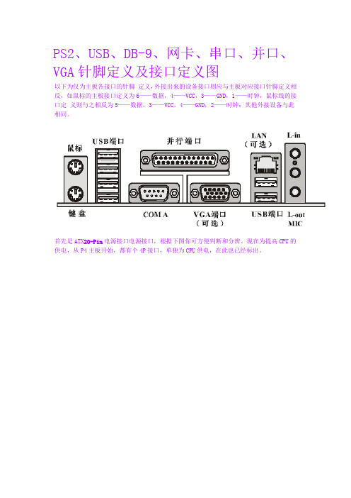
PS2、USB、DB-9、网卡、串口、并口、VGA针脚定义及接口定义图以下为仅为主板各接口的针脚定义,外接出来的设备接口则应与主板对应接口针脚定义相反,如鼠标的主板接口定义为6——数据,4——VCC,3——GND,1——时钟,鼠标线的接口定义则与之相反为5——数据,3——VCC,4——GND,2——时钟;其他外接设备与此相同。
首先是ATX20-Pin电源接口电源接口,根据下图你可方便判断和分辨。
现在为提高CPU的供电,从P4主板开始,都有个4P接口,单独为CPU供电,在此也已经标出。
鼠标和键盘绝大多数采用PS/2接口,鼠标和键盘的PS/2接口的物理外观完全相同,初学者往往容易插错,以至于业界不得不在PC'99规范中用两种不同的颜色来将其区别开,而事实上它们在工作原理上是完全相同的,从下面的PS/2接口针脚定义我们就可以看出来。
上图的分别为AT键盘(既常说的大口键盘),和PS2键盘(即小口键盘),如今市场上PS2键盘的数量越来越多了,而AT键盘已经要沦为昨日黄花了。
因为键盘的定义相似,所以两者有共同的地方,各针脚定义如下:1、DATA 数据信号2、空3、GND 地端4、+5V5、CLOCK 时钟6 空(仅限PS2键盘)USB(Universal Serial Bus,通用串行总线)接口是由Compaq、IBM、Microsoft等多家公司于1994年底联合提出的接口标准,其目的是用于取代逐渐不适应外设需求的传统串、并口。
1996年业界正式通过了USB1.0标准,但由于未获当时主流的Win95支持(直到Win95 OSR2才通过外挂模块提供对USB1.0的支持)而未得到普及,直到1998年USB1.1标准确立和Win98内核正式提供对USB接口的直接支持之后,USB才真正开始普及,到今天已经发展到USB2.0标准。
USB接口的连接线有两种形式,通常我们将其与电脑接口连接的一端称为“A”连接头,而将连接外设的接头称为“B”连接头(通常的外设都是内建USB数据线而仅仅包含与电脑相连的“A”连接头)。
赛米控、英飞凌三电平方案使用说明书

西门康、英飞凌三电平驱动方案2AB30A17K‐3L‐I/S是基于青铜剑自主开发的2QD30A17K‐I驱动核的驱动底座,为英飞凌和西门康三电平IGBT而设计。
2AB30A17K‐3L‐I/S可以驱动西门康SKiM601TMLI12E4B 和英飞凌F3L400R12PT4_B26三电平IGBT模块。
外置两组驱动接口使得它可以支持2单元SKiM601TMLI12E4B和F3L400R12PT4_B26的并联。
图 1 2AB30A17K‐3L实物图目 录驱动方案概述 (3)基本电气特性 (驱动核2QD30A17K‐I) (4)底座板和门极板尺寸图 (5)底座板和门极板引脚接口定义 (8)2AB30A17K‐3L 原边牛角引脚定义 (8)2AB30A17K‐3L次边接口定义 (8)MA20A12K‐3L‐S接口定义 (9)MA20A12K‐3L‐I接口定义 (9)底座板门极板电路原理图 (10)2AB30A17K‐3L 电路原理图 (10)MA20A12K‐3L‐S电路原理图 (13)MA20A12K‐3L‐I电路原理图 (15)2AB30A17K‐3L‐I/S牛角接口电路描述 (17)概述 (17)VCC端口 (17)VDC端口 (17)MOD端口(模式选择端) (17)直接模式 (17)半桥模式 (18)INA、INB(PWM信号输入) (18)SO1、SO2(故障输出) (18)底座板与门极板连接描述 (19)概述 (19)2AB30A17K‐3L与MA20A12K‐3L‐S连接示意图 (19)2AB30A17K‐3L与MA20A12K‐3L‐I连接示意图 (19)联系我们 (20)驱动方案概述2AB30A17K‐3L‐I/S采用了青铜剑公司自主开发的驱动核(2QD30A17K‐I)+适配底座(2AB30A17K‐3L)+SKiM601TMLI12E4B或F3L400R12PT4_B26 IGBT门极适配板(MA20A12K‐3L‐S或MA20A12K‐3L‐I)设计而成,是一款使用方便、成本低的IGBT驱动方案。
H3C_smartlink技术原理与配置指导

1 Smart Link配置 .................................................................................................................................... 1-11.1 Smart Link简介................................................................................................................................. 1-11.1.1 Smart Link概念介绍............................................................................................................... 1-11.1.2 Smart Link运行机制............................................................................................................... 1-21.2 配置Smart Link设备........................................................................................................................ 1-31.2.1 配置准备 ................................................................................................................................ 1-31.2.2 配置Smart Link设备 ............................................................................................................. 1-31.2.3 Smart Link设备配置举例........................................................................................................ 1-41.3 配置相关设备.................................................................................................................................... 1-51.3.1 配置相关设备 ......................................................................................................................... 1-51.3.2 相关设备配置举例.................................................................................................................. 1-51.4 Smart Link显示和维护...................................................................................................................... 1-61.5 Smart Link典型配置举例 .................................................................................................................. 1-61.5.1 单Smart Link组配置举例...................................................................................................... 1-61.5.2 多Smart Link组负载分担配置举例........................................................................................ 1-81 Smart Link 配置1.1 Smart Link 简介如图1-1所示,双上行组网是目前常用组网之一。
三层交换机原理解析
三层交换机原理解析1.硬件结构:三层交换机通常由交换芯片、路由芯片和控制芯片组成。
交换芯片负责局部网络内的数据包转发,路由芯片负责不同网络之间的路由选择和转发,控制芯片实现管理和控制功能。
2.数据包的转发:当三层交换机收到一个数据包时,会首先进行数据包解析,提取出源地址和目的地址等信息。
然后,交换芯片会根据目的地址查询自己的转发表,并将数据包转发给相应的端口。
如果目的地址不在转发表中,交换芯片会将数据包转发给路由芯片进行进一步转发。
3.转发表的更新:为了实现数据包的快速转发,交换芯片会维护一个转发表。
该转发表记录了不同设备的MAC地址和相应的端口信息。
通常,转发表会通过链路层的协议(如ARP)来获得和更新设备的MAC地址。
当网络中的设备进行通信时,交换芯片会根据转发表来决定转发路径。
4.路由选择:当数据包需要跨越不同网络时,交换芯片会将数据包转发给路由芯片进行路由选择。
路由芯片通过学习网络拓扑和掌握网络的路由信息,来选择最佳的路由路径,并且将数据包转发到合适的出口端口。
5.VLAN划分:三层交换机支持虚拟局域网(VLAN)的划分。
VLAN的划分可以将一个物理网络划分成多个逻辑上的子网,不同的子网可以根据需要进行独立的管理和配置。
VLAN的划分可以提高网络的安全性和性能。
6.数据包过滤:三层交换机可以通过过滤规则对数据包进行过滤。
过滤规则可以根据源地址、目的地址、协议类型等条件进行设置,从而实现对网络中的数据包进行控制和管理。
7.流量控制:三层交换机支持流量控制功能,可以根据网络的负载情况和带宽情况来控制端口的传输速率。
通过流量控制,可以防止网络拥塞和丢包现象的发生,从而提高网络的性能和稳定性。
总结起来,三层交换机通过硬件实现了路由和交换功能,并且支持VLAN划分、数据包过滤和流量控制等功能。
它可以在局部网络中快速转发数据包,并且能够跨越不同网络进行路由选择和转发,从而提高了网络的性能和可靠性。
sata电源及信号接口定义
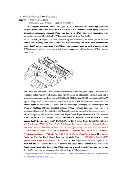
SATA15针电源接口定义/sata信号线定义2010年04月07日星期三14:46这些天在写esata的驱动,所以将相关资料贴上!•In computer hardware, Serial ATA(SATA, is a computer bus technology primarily designed for transfer of data to and from a hard disk. It is the successor to the legacy Advanced Technology Attachment standard (ATA, also known as IDE). This older technology was retroactively renamed Parallel ATA (PA TA) to distinguish it from Serial ATA.The Serial ATA [SATA] bus is defined over two separate connectors, one connector for the data lines and one for the power lines. A Serial ATA Hard drive may also have a third connector for legacy PATA power connections. The PATA power connector may be used in instead of the SATA power to supply a connection which is more rugged and reliable then the SATA-1 power connection.The Serial ATA interface [SATA] is the serial version of the IDE [ATA] spec. SATA uses a 4 conductor cable with two differential pairs [Tx/Rx], plus an additional 3 grounds pins and a separate power connector. Data runs at 150MBps [1.5GHz] using 8B/10B encoding and 250mV signal swings, with a maximum bus length of 1 meter. SATA enhancements move the data transfer speed to; 300MBps [3.0Gbps], and then 600MBps [6.0Gbps]. The current speed for SATA is 300Mbps [3Gbps]. Shielded external SATA [eSATA] data cable runs out to a maximum of between 3 feet and 6 feet. eSATA cables are used external to the chassis or case.SATA Data pinout SATA PinOut, Data Pin #Signal Name Signal Description1 GND Ground 2A+ Transmit + 3A- Transmit - 4GND Ground 5B- Receive - 6B+ Receive + 7GND Ground SATA Power pinout SATA PinOut, Power Pin #Signal Name Signal Description1 V33 3.3v Power 2 V33 3.3v Power 3 V33 3.3v Power, Pre-charge, 2nd mate 4 Ground 1st Mate5 Ground 2nd Mate6 Ground 3rd Mate7 V5 5v Power, pre-charge, 2nd mate8 V5 5v Power 9V5 5v Power 10 Ground 2nd Mate 11 Reserved - 12 Ground 1st Mate 13 V12 12v Power, Pre-charge, 2nd mate 14 V12 12v Power 15 V12 12v Power PATA Power pinout IDE Power Connector Pin Out Pin #Signal Function18 A WG Wire 1 +12V DC Yellow 2 +12V Return Black 3 +5V Return Black 4 +5V DC Red SATA signal names are with respect to the Host, the device connected to the host reverses the signal names. Transmit pins connect to Receive pins on the other device. The SATA connector is keyed at pin 1. These pin outs for the Serial ATA connector are not compatible with the legacy PATA connector.[The following article is licensed under the GNU Free Documentation License. It reproduces the Wikipedia article "Serial ATA"]SATA 1.5 Gb/sFirst-generation Serial ATA interfaces, also known as SATA/150, run at 1.5 Gigahertz (GHz). Serial A TA uses 8B/10B encoding at the physical layer. This encoding scheme has an efficiency of 80%, resulting in an actual data transfer rate of 1.2 Gigabits per second (Gb/s), or 150 megabytes per second (MB/s). The relative simplicity of a serial link and the use of LVDS allow both the use of longer drive cables and an easier transition path to higher speeds.SATA 3.0 Gb/sSoon after SATA's introduction, enhancements were made to the standard. A 3Gb/s signalling rate was added to the PHY layer, offering up to twice the data throughput. To ensure seamless backward compatibility between older SATA and the newer faster SATA/3Gbs devices, the latter devices are required to support the original 1.5Gb/s rate. In practice, some older SATA systems that do not support SATA speed negotiation require the peripheral drive's speed be manually hardlimited to 150Â MB/s with the use of a jumper for a 300Â MB/s drive.Like SATA 1.5Gb/s, SATA 3Gb/s uses 8B/10B encoding resulting in an actual data transfer rate of 2.4 Gb/s, or 300 MB/s.The 3.0Â Gb/s specification has been very widely referred to as “Serial ATA II” (“SATA II”), contrary to the wishes of the Serial ATA standards organization that authored it. The official website notes that SATA II was in fact that organization's name at the time, the SATA 3Gb/s specification being only one of many that the former SATA II defined, and suggests that “SA TA 3Gb/s” be used instead. (The Serial A TA standards organization has since changed names, and is now “The Serial ATA International Organization”, abbreviated SA TA-IO.) SATA-IO plans to further increase the maximum throughput of Serial ATA to 600Â MB/s around the year 2007.SATA 3Gb/s is sometimes also referred to as SATA/300 or SATA II, continuing the line of PATA/100, PATA/133 and SATA/150.SATA 6.0 Gb/sSATA-IO plans to make a 6.0 Gb/s standard. Although the theoretical thoroughput would be doubled, conventional hard disks can't approach saturating this speed. Serial ATA innovationsSATA drops the master/slave shared bus of PATA, giving each device a dedicated cable and dedicated bandwidth. While this requires twice the number of host controllers to support the same number of SATA devices, at the time of SATA's introduction this was no longer a significant drawback. Another controller could be added into a controller ASIC at little cost beyond the addition of the extra seven signal lines and printed circuit board (PCB) space for the cable header.Features allowed for by SATA but not by PA TA include hot-swapping and native command queueing.To ease their transition to SATA, many manufacturers have produced drives which use controllers largely identical to those on their PATA drives and include a bridge chip on the logic board. Bridged drives have a SATA connector, may include either or both kinds of power connectors, and generally perform identically to native drives. They may, however, lack support for some SATA-specific features. As of 2004, all major hard drive manufacturers produce either bridged or native SA TA drives.SATA drives may be plugged into Serial Attached SCSI (SAS) controllers and communicate on the same physical cable as native SAS disks. SAS disks, however, may not be plugged into aSATA controller.Cables and ConnectorsPhysically, the SATA power and data cables are the most noticeable change from Parallel A TA. The SATA standard defines a data cable using seven conductors and 8Â mm wide wafer connectors on each end. SATA cables can be up to 1 m (39 in) long.PATA ribbon cables, in comparison, carry either 40- or 80-conductor wires and are limited to 46 cm (18 in) in length. The reduction in conductors makes SATA connectors and cables much narrower than those of PATA, thus making them more convenient to route within tight spaces and reducing obstructions to air cooling. Unlike early PATA connectors, SATA connectors are keyed — it is not possible to install cable connectors upside down without considerable force.The SATA standard also specifies a power connector sharply differing from the four-pin Molex connector used by PATA drives and many other computer components. Like the data cable, it is wafer-based, but its wider 15-pin shape should prevent confusion between the two. The seemingly large number of pins are used to supply three different voltages if necessary —3.3Â V, 5Â V, and 12Â V. Each voltage is supplied by three pins gangedtogether (and 5 pins for ground). This is because the small pins cannot supply sufficient current for some devices, so they are combined. One pin from each of the three voltages is also used for hotplugging. The same physical connections are used on 3.5-in (90mm) and 2.5-in (70mm) (notebook) hard disks. Some SATA drives include in PA TA style four-pin Molex connector for use with power supplies that lack the SATA power connector. Also, adaptors are available to convert a PATA style power connector to SATA power connector.External SATAeSATA was standardized in mid-2004, with specifically defined cables, connectors, and signal requirements for external SATA drives. eSATA is characterized by:Full SATA speed for external disks (115MB/s have been measured with external RAID enclosures)•No protocol conversion from IDE/SATA to USB/Firewire, all disk features are available to the host•Cable length is restricted to 2m, USB and Firewire span longer distances.•Minimum and maximum transmit voltage decreased to 400mV - 500mV•Minimum and maximum receive voltage decreased to 240mV - 500mVUSB and Firewire require conversion of all communication with the external disk, so external USB/Firewire enclosures include an IDE or SATA bridge chip that translates from the ATA protocol to USB or Firewire. Drive features like S.M.A.R.T. cannot be exploited that way and the achiveable transfer speed with USB/Firewire is only about half of the entire bus data rate of about 50MB/s. This limited effective data transfer rate becomes very visible when using an external RAID array and also with fast single disks which may yield well over 70MB/s during real use.Currently, most PC motherboards do not have an eSA TA connector. eSATA may be enabled through the addition of an eSATA host bus adapter (HBA) or bracket connector for desktop systems or with a Cardbus or ExpressCard for notebooks.Note:Prior to the final specification for eSATA, there were a number of products designed for external connections of SATA drives. Some of these use the internal SATA connector or even connectors designed for other interface specifications, such as IEEE 1394. These products are not eSA TA compliant.eSATA does not provide power, which means that external 2.5" disks which would otherwise be powered over the USB or Firewire cable need a separate power cable when connected over eSATA.eSATA compared to other buseseSA TA PATA Fire Wire 1394b USB 2.0 Actual Speed 2.4 >Gib/s 1064 Mib/s 786 Mib/s ~375 Mib/sMax. cable length 2 meters 46 centimetres4.5 meters 16 cables canbedaisy chained up to 72meters5 metersPower cablerequired?Yes Yes No NoDevices per Channel 1 (5 withmultiplier)3 (3rd deviceread only)63 127Backward compatibilityThe backward compatibility of SATA hard discs is virtually non-existent in the sense that SATA drives will not work with the same connectors that IDE, SCSI, or any other format of hard drive connect to. It is, however, possible to purchase convertors that attach to the rear of the SATA hard disc and will allow it to function as an IDE drive. This can prove useful in situations where one wishes to use their SATA drive on older motherboards that may not have SATA connections, etc.SATA vs SCSISCSI currently offers transfer rates higher than SATA, but is a more complex bus usually resulting in higher costs to the user. Some drive manufacturers offer longer warranties for SCSI devices, however, indicating a possibly higher manufacturing quality control of SCSI devices compared to PATA/SA TA devices.conn_sata.gif(10.79 KB)3030299030-SATA-15P-RA-core-power-connector-dwg.gif(14.14 KB)类别:电脑技术| | 添加到搜藏| 分享到i贴吧| 浏览(1386) | 评论(0)。