M25P40-VMP3中文资料
M25P128中文资料

M25P128
128 Mbit (Multilevel), low-voltage, Serial Flash memory with 50-MHz SPI bus interface
Feature summary
■ 128 Mbit of Flash memory ■ 2.7 to 3.6 V single supply voltage ■ SPI bus compatible Serial interface ■ 50 MHz clock rate (maximum) ■ VPP = 9 V for fast Program/Erase mode
5
Memory organization . . . . . . . . . . . . . . . . . . . . . . . . . . . . . . . . . . . . . . . 16
6
Instructions . . . . . . . . . . . . . . . . . . . . . . . . . . . . . . . . . . . . . . . . . . . . . . . 19
2.4 Chip Select (S) . . . . . . . . . . . . . . . . . . . . . . . . . . . . . . . . . . . . . . . . . . . . . . 8
2.5 Hold (HOLD) . . . . . . . . . . . . . . . . . . . . . . . . . . . . . . . . . . . . . . . . . . . . . . . . 8
4.5 Active power and standby power modes . . . . . . . . . . . . . . . . . . . . . . . . . 13
MEMORY存储芯片M25P64-VME6TG中文规格书
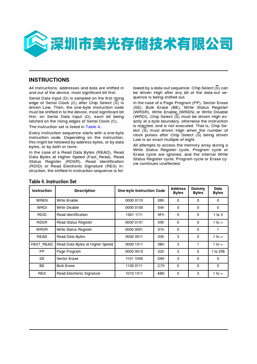
INSTRUCTIONSAll instructions, addresses and data are shifted in and out of the device, most significant bit first.Serial Data Input (D) is sampled on the first rising edge of Serial Clock (C) after Chip Select (S) is driven Low. Then, the one-byte instruction code must be shifted in to the device, most significant bit first, on Serial Data Input (D), each bit being latched on the rising edges of Serial Clock (C).The instruction set is listed in Table 4..Every instruction sequence starts with a one-byte instruction code. Depending on the instruction,this might be followed by address bytes, or by data bytes, or by both or none.In the case of a Read Data Bytes (READ), Read Data Bytes at Higher Speed (Fast_Read), Read Status Register (RDSR), Read Identification (RDID) or Read Electronic Signature (RES) in-struction, the shifted-in instruction sequence is fol-lowed by a data-out sequence. Chip Select (S) can be driven High after any bit of the data-out se-quence is being shifted out.In the case of a Page Program (PP), Sector Erase (SE), Bulk Erase (BE), Write Status Register (WRSR), Write Enable (WREN) or Write Disable (WRDI), Chip Select (S) must be driven High ex-actly at a byte boundary, otherwise the instruction is rejected, and is not executed. That is, Chip Se-lect (S) must driven High when the number of clock pulses after Chip Select (S) being driven Low is an exact multiple of eight.All attempts to access the memory array during a Write Status Register cycle, Program cycle or Erase cycle are ignored, and the internal Write Status Register cycle, Program cycle or Erase cy-cle continues unaffected.Table 4. Instruction SetInstructionDescriptionOne-byte Instruction CodeAddressBytesDummyBytesData Bytes WREN Write Enable 0000 011006h 000WRDI Write Disable 0000 010004h 000RDID Read Identification 1001 11119Fh 0 0 1 to 3RDSR Read Status Register 0000 010105h 0 0 1 to ∞WRSR Write Status Register 0000 000101h 0 0 1 READRead Data Bytes0000 001103h 30 1 to ∞FAST_READ Read Data Bytes at Higher Speed0000 10110Bh 31 1 to ∞PP Page Program 0000 001002h 30 1 to 256SESector Erase1101 1000D8h 3 0 0 BE Bulk Erase 1100 0111C7h 000RESRead Electronic Signature1010 1011ABh31 to ∞Write Enable (WREN)The Write Enable (WREN) instruction (Figure 9.) sets the Write Enable Latch (WEL) bit.The Write Enable Latch (WEL) bit must be set pri-or to every Page Program (PP), Sector Erase (SE), Bulk Erase (BE) and Write Status Register (WRSR) instruction.The Write Enable (WREN) instruction is entered by driving Chip Select (S) Low, sending the in-struction code, and then driving Chip Select (S) High.Write Disable (WRDI)The Write Disable (WRDI) instruction (Figure 10.) resets the Write Enable Latch (WEL) bit.The Write Disable (WRDI) instruction is entered by driving Chip Select (S) Low, sending the instruc-tion code, and then driving Chip Select (S) High. The Write Enable Latch (WEL) bit is reset under the following conditions: –Power-up–Write Disable (WRDI) instruction completion –Write Status Register (WRSR) instruction completion–Page Program (PP) instruction completion –Sector Erase (SE) instruction completion–Bulk Erase (BE) instruction completionRead Data Bytes at Higher Speed(FAST_READ)The device is first selected by driving Chip Select (S)Low. The instruction code for the Read Data Bytes at Higher Speed (FAST_READ) instruction is followed by a 3-byte address (A23-A0) and a dummy byte, each bit being latched-in during the rising edge of Serial Clock (C). Then the memory contents, at that address, is shifted out on Serial Data Output (Q), each bit being shifted out, at a maximum frequency f C, during the falling edge of Serial Clock (C).The instruction sequence is shown in Figure 15.. The first byte addressed can be at any location. The address is automatically incremented to the next higher address after each byte of data is shift-ed out. The whole memory can, therefore, be read with a single Read Data Bytes at Higher Speed (FAST_READ) instruction. When the highest ad-dress is reached, the address counter rolls over to 000000h, allowing the read sequence to be contin-ued indefinitely.The Read Data Bytes at Higher Speed (FAST_READ) instruction is terminated by driving Chip Select (S) High. Chip Select (S) can be driv-en High at any time during data output. Any Read Data Bytes at Higher Speed (FAST_READ) in-struction, while an Erase, Program or Write cycle is in progress, is rejected without having any ef-fects on the cycle that is in progress.M25P64Page Program (PP)The Page Program (PP) instruction allows bytes to be programmed in the memory (changing bits from 1 to 0). Before it can be accepted, a Write Enable (WREN) instruction must previously have been ex-ecuted. After the Write Enable (WREN) instruction has been decoded, the device sets the Write En-able Latch (WEL).The Page Program (PP) instruction is entered by driving Chip Select (S) Low, followed by the in-struction code, three address bytes and at least one data byte on Serial Data Input (D). If the 8 least significant address bits (A7-A0) are not all zero, all transmitted data that goes beyond the end of the current page are programmed from the start address of the same page (from the address whose 8 least significant bits (A7-A0) are all zero). Chip Select (S) must be driven Low for the entire duration of the sequence.The instruction sequence is shown in Figure 16.. If more than 256 bytes are sent to the device, pre-viously latched data are discarded and the last 256 data bytes are guaranteed to be programmed cor-rectly within the same page. If less than 256 Data bytes are sent to device, they are correctly pro-grammed at the requested addresses without hav-ing any effects on the other bytes of the same page.Chip Select (S) must be driven High after the eighth bit of the last data byte has been latched in, otherwise the Page Program (PP) instruction is not executed.As soon as Chip Select (S) is driven High, the self-timed Page Program cycle (whose duration is t PP) is initiated. While the Page Program cycle is in progress, the Status Register may be read to check the value of the Write In Progress (WIP) bit. The Write In Progress (WIP) bit is 1 during the self-timed Page Program cycle, and is 0 when it is completed. At some unspecified time before the cycle is completed, the Write Enable Latch (WEL) bit is reset.A Page Program (PP) instruction applied to a page which is protected by the Block Protect (BP2, BP1, BP0) bits (see Table 2. and Table 3.) is not execut-ed.M25P64。
联想2200-参考手册
MEMORY存储芯片M25P16-VMN3TPB中文规格书

Features•SPI bus compatible serial interface •16Mb Flash memory•75 MHz clock frequency (maximum)•2.7V to 3.6V single supply voltage•Page program (up to 256 bytes) in 0.64ms (TYP)•Erase capability–Sector erase: 512Kb in 0.6 s (TYP)–Bulk erase: 16Mb in 13 s (TYP)•Write protection–Hardware write protection: protected area size defined by non-volatile bits BP0, BP1, BP2•Deep power down: 1µA (TYP)•Electronic signature–JEDEC standard 2-byte signature (2015h)–Unique ID code (UID) and 16 bytes of read-only data, available upon customer request–RES command, one-byte signature (14h) for backward compatibility•More than 100,000 write cycles per sector •More than 20 years data retention •Automotive grade parts available •Packages (RoHS compliant)–SO8N (MN) 150 mils –SO8W (MW) 208 mils –SO16 (MF) 300 mils–VFDFPN8 (MP) MLP8 6mm x 5mm –VFDFPN8 (ME) MLP8 8mm x 6mm –UFDFPN8 (MC) MLP8 4mm x 3mm找Memory 、FPGA 、二三极管、连接器、模块、光耦、电容电阻、单片机、处理器、晶振、传感器、 滤波器,上深圳市美光存储技术有限公司Functional DescriptionThe M25P16 is an 16Mb (2Mb x 8) serial Flash memory device with advanced write pro-tection mechanisms accessed by a high speed SPI-compatible bus. The device supportshigh-performance commands for clock frequency up to 75MHz.The memory can be programmed 1 to 256 bytes at a time using the PAGE PROGRAMcommand. It is organized as 32 sectors, each containing 256 pages. Each page is 256bytes wide. Memory can be viewed either as 8,192 pages or as 2,097,152 bytes. The en-tire memory can be erased using the BULK ERASE command, or it can be erased onesector at a time using the SECTOR ERASE command.This datasheet details the functionality of the M25P16 device based on 110nm process.Figure 2: Pin Connections: SO8, VFQFPN , VDFPN1234V CC HOLD#5678DQ1V SSS#DQ0C W#Note:1.There is an exposed central pad on the underside of the MLP8 package that is pulled in-ternally to V SS , and must not be connected to any other voltage or signal line on the PCB. The Package Mechanical section provides information on package dimensions and how to identify pin 1.Figure 3: Pin Connections: SO16123416151413V CC HOLD#DNU DNU DNU DNU DNU DNU DNU DNU 56781211109DQ1V SS S#DQ0C W#/V PPNotes:1.DU = Don't Use2.The Package Mechanical section provides information on package dimensions and howto identify pin 1.Operating FeaturesPage ProgrammingTo program one data byte, two commands are required: WRITE ENABLE, which is onebyte, and a PAGE PROGRAM sequence, which is four bytes plus data. This is followed bythe internal PROGRAM cycle of duration t PP. To spread this overhead, the PAGE PRO-GRAM command allows up to 256 bytes to be programmed at a time (changing bitsfrom 1 to 0), provided they lie in consecutive addresses on the same page of memory. Tooptimize timings, it is recommended to use the PAGE PROGRAM command to programall consecutive targeted bytes in a single sequence than to use several PAGE PROGRAMsequences with each containing only a few bytes.Status RegisterThe status register contains a number of status and control bits that can be read or set(as appropriate) by specific commands. For a detailed description of the status registerbits, see READ STATUS REGISTER (page 25).Data Protection by ProtocolNon-volatile memory is used in environments that can include excessive noise. The fol-lowing capabilities help protect data in these noisy environments.Power on reset and an internal timer (t PUW) can provide protection against inadvertentchanges while the power supply is outside the operating specification.PROGRAM, ERASE, and WRITE STATUS REGISTER commands are checked before theyare accepted for execution to ensure they consist of a number of clock pulses that is amultiple of eight.All commands that modify data must be preceded by a WRITE ENABLE command to setthe write enable latch (WEL) bit.In addition to the low power consumption feature, the DEEP POWER-DOWN mode of-fers extra software protection since all PROGRAM, and ERASE commands are ignoredwhen the device is in this mode.Software Data ProtectionMemory can be configured as read-only using the block protect bits (BP2, BP1, BP0) asshown in the Protected Area Sizes table.Hardware Data ProtectionHardware data protection is implemented using the write protect signal applied on theW# pin. This freezes the status register in a read-only mode. In this mode, the block pro-tect (BP) bits and the status register write disable bit (SRWD) are protected.Table 3: Protected Area SizesNote: 1.0 0 = unprotected area (sectors): The device is ready to accept a BULK ERASE commandonly if all block protect bits (BP1, BP0) are 0.Table 4: Protected Area Sizes。
MEMORY存储芯片M25P16-VMP6TG中文规格书
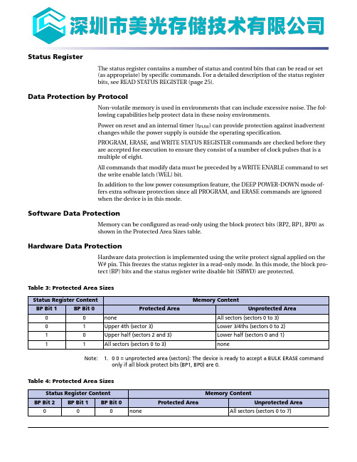
Status RegisterThe status register contains a number of status and control bits that can be read or set(as appropriate) by specific commands. For a detailed description of the status registerbits, see READ STATUS REGISTER (page 25).Data Protection by ProtocolNon-volatile memory is used in environments that can include excessive noise. The fol-lowing capabilities help protect data in these noisy environments.Power on reset and an internal timer (t PUW) can provide protection against inadvertentchanges while the power supply is outside the operating specification.PROGRAM, ERASE, and WRITE STATUS REGISTER commands are checked before theyare accepted for execution to ensure they consist of a number of clock pulses that is amultiple of eight.All commands that modify data must be preceded by a WRITE ENABLE command to setthe write enable latch (WEL) bit.In addition to the low power consumption feature, the DEEP POWER-DOWN mode of-fers extra software protection since all PROGRAM, and ERASE commands are ignoredwhen the device is in this mode.Software Data ProtectionMemory can be configured as read-only using the block protect bits (BP2, BP1, BP0) asshown in the Protected Area Sizes table.Hardware Data ProtectionHardware data protection is implemented using the write protect signal applied on theW# pin. This freezes the status register in a read-only mode. In this mode, the block pro-tect (BP) bits and the status register write disable bit (SRWD) are protected.Table 3: Protected Area SizesNote: 1.0 0 = unprotected area (sectors): The device is ready to accept a BULK ERASE commandonly if all block protect bits (BP1, BP0) are 0.Table 4: Protected Area SizesNote: 1.0 0 0 = unprotected area (sectors): The device is ready to accept a BULK ERASE command only if all block protect bits (BP2, BP1, BP0) are 0.质量等级领域:宇航级IC、特军级IC、超军级IC、普军级IC、禁运IC、工业级IC,军级二三极管,功率管等;应用领域:航空航天、船舶、汽车电子、军用计算机、铁路、医疗电子、通信网络、电力工业以及大型工业设备祝您:工作顺利,生活愉快!以深圳市美光存储技术有限公司提供的参数为例,以下为M25P16-VMP6TG的详细参数,仅供参考Table 10: Command Set Codes。
MEMORY存储芯片M25P40-VMN6TPB中文规格书

AC CharacteristicsIn the following AC specifications, output HIGH-Z is defined as the point where data out is no longer driven; however, this is not applicable to the M25PX64 device.Table 21: Device Grade and AC Table CorrelationTable 22: AC Measurement ConditionsFigure 23: AC Measurement I/O WaveformInput and output timing reference levelsInput levels 0.8V CC0.2V CC0.7V CC 0.3V CC0.5V CCTable 23: CapacitanceNote:1.Values are sampled only, not 100% tested, at T A =25°C and a frequency of 25MHz.Table 24: Instruction Times, Process TechnologyNotes: 1.Applies to the entire table: 110nm technology devices are identified by the process iden-tification digit 4 in the device marking and the process letter B in the part number.2.When using the PAGE PROGRAM command to program consecutive bytes, optimizedtimings are obtained in one sequence that includes all the bytes rather than in severalsequences of only a few bytes (1 < n < 256).Table 25: AC Specifications (25 MHz, Device Grade 3, V CC[min]=2.7V)Table 25: AC Specifications (25 MHz, Device Grade 3, V CC[min]=2.7V) (Continued)Notes: 1.READ DATA BYTES at HIGHER SPEED, PAGE PROGRAM, SECTOR ERASE, BLOCK ERASE,DEEP POWER-DOWN, READ ELECTRONIC SIGNATURE, WRITE ENABLE/DISABLE, READ ID,READ/WRITE STATUS REGISTER2.The t CH and t CL signals must be greater than or equal to 1/f C.3.The t CLCH, t CHCL, t SHQZ, t HHQX, t HLQZ, t DP, t RES1, and t RES2 signal values are guaranteed bycharacterization, not 100% tested in production.4.The t CLCH and t CHCL signals clock rise and fall time values are expressed as a slew-rate.5.The t WHSL and t SHWL signals are only applicable as a constraint for a WRITE STATUS REGIS-TER command when SRWD bit is set at 1.Table 26: AC Specifications (50 MHz, Device Grade 6, V CC[min]=2.7V)Table 26: AC Specifications (50 MHz, Device Grade 6, V CC[min]=2.7V) (Continued)Notes: 1.READ DATA BYTES at HIGHER SPEED, PAGE PROGRAM, SECTOR ERASE, BLOCK ERASE,DEEP POWER-DOWN, READ ELECTRONIC SIGNATURE, WRITE ENABLE/DISABLE, READ ID,READ/WRITE STATUS REGISTER2.The t CH and t CL signals must be greater than or equal to 1/f C.3.The t CLCH, t CHCL, t SHQZ, t HHQX, t HLQZ, t DP, t RES1, and t RES2 signal values are guaranteed bycharacterization, not 100% tested in production.4.The t CLCH and t CHCL signals clock rise and fall time values are expressed as a slew-rate.5.The t WHSL and t SHWL signals are only applicable as a constraint for a WRITE STATUS REGIS-TER command when SRWD bit is set at 1.Table 27: AC Specifications (40 MHz, Device Grade 6, V CC[min]=2.3V)。
施耐德变频器选型手册
1
选型指导
产品类型
软起动器
通用型变频器
C 应用:
C 应用:
C 应用:
压缩机、泵、风机等 压缩机、泵、风机、 泵、风机等 大惯性机械、传送 装置。
耐德电气从一个优秀的产品和设备供应商逐步成长为整体解决方案提供商。今年,施耐德电气首
次集成其在建筑楼宇、IT、安防、电力及工业过程和设备等五大领域的专业技术和经验,将其高
质量的产品和解决方案融合在一个统一的架构下,通过标准的界面为各行业客户提供一个开放、
透明、节能、高效的 运营成本。
能效管理平台,为企业客户节省高达30%的投资成本和
电机功率 变频器
输出频率
4...400 kW –
控制类型 异步电机 可配置的电压斜坡 控制
同步电机 –
瞬时过转矩
–
功能
功能数量
预置多段速度的数目
I/O 的数目 模拟输入
逻辑输入
模拟输出
逻辑输出
继电器输出
通讯
集成通讯协议
可选配件
36 – 1 PTC 探头 3 – – 2 Modbus –
卡 (可选配件)
2
复杂、大功率变频器
C 应用:
泵、多泵、风机、压缩机 风机、泵、压缩机,各种标准 转矩应用
C 应用:
传送带、搅拌机、挤出机、 起重等
C 应用:
电力、采矿和选矿、石油和天 然气、水处理等中压系统中的 风机、泵、压缩机等
C 应用:
起重应用、下坡输送带、绞盘、自动扶 梯、高动态驱动器、泵/涡轮组合等
常用三极管参数大全

玉林万顺达电脑芯片级维修资料 2010-07-20整理玉林万顺达电脑芯片级维修资料 2010-07-20整理玉林万顺达电脑芯片级维修资料 2010-07-20整理玉林万顺达电脑芯片级维修资料 2010-07-20整理玉林万顺达电脑芯片级维修资料 2010-07-20整理玉林万顺达电脑芯片级维修资料 2010-07-20整理玉林万顺达电脑芯片级维修资料 2010-07-20整理玉林万顺达电脑芯片级维修资料 2010-07-20整理玉林万顺达电脑芯片级维修资料 2010-07-20整理玉林万顺达电脑芯片级维修资料 2010-07-20整理玉林万顺达电脑芯片级维修资料 2010-07-20整理玉林万顺达电脑芯片级维修资料 2010-07-20整理玉林万顺达电脑芯片级维修资料 2010-07-20整理玉林万顺达电脑芯片级维修资料 2010-07-20整理玉林万顺达电脑芯片级维修资料 2010-07-20整理玉林万顺达电脑芯片级维修资料 2010-07-20整理玉林万顺达电脑芯片级维修资料 2010-07-20整理玉林万顺达电脑芯片级维修资料 2010-07-20整理玉林万顺达电脑芯片级维修资料 2010-07-20整理玉林万顺达电脑芯片级维修资料 2010-07-20整理玉林万顺达电脑芯片级维修资料 2010-07-20整理玉林万顺达电脑芯片级维修资料 2010-07-20整理玉林万顺达电脑芯片级维修资料 2010-07-20整理玉林万顺达电脑芯片级维修资料 2010-07-20整理玉林万顺达电脑芯片级维修资料 2010-07-20整理玉林万顺达电脑芯片级维修资料 2010-07-20整理玉林万顺达电脑芯片级维修资料 2010-07-20整理玉林万顺达电脑芯片级维修资料 2010-07-20整理玉林万顺达电脑芯片级维修资料 2010-07-20整理玉林万顺达电脑芯片级维修资料 2010-07-20整理。
- 1、下载文档前请自行甄别文档内容的完整性,平台不提供额外的编辑、内容补充、找答案等附加服务。
- 2、"仅部分预览"的文档,不可在线预览部分如存在完整性等问题,可反馈申请退款(可完整预览的文档不适用该条件!)。
- 3、如文档侵犯您的权益,请联系客服反馈,我们会尽快为您处理(人工客服工作时间:9:00-18:30)。
M25P404 Mbit, Low Voltage, Serial Flash MemoryWith 40MHz SPI Bus InterfaceFEATURES SUMMARY■ 4 Mbit of Flash Memory Array■Page Program (up to 256 Bytes) in 1.5ms(typical)■Sector Erase (512 Kbit) in 1s (typical)■Bulk Erase (4 Mbit) in 4.5s (typical)■ 2.7 to 3.6V Single Supply Voltage■SPI Bus Compatible Serial Interface■40MHz Clock Rate (maximum)■Deep Power-down Mode 1µA (typical)■Electronic Signature (12h)August 20041/40M25P40TABLE OF CONTENTSFEATURES SUMMARY . . . . . . . . . . . . . . . . . . . . . . . . . . . . . . . . . . . . . . . . . . . . . . . . . . . . . . . . . . . . .1 Figure 1.Packages. . . . . . . . . . . . . . . . . . . . . . . . . . . . . . . . . . . . . . . . . . . . . . . . . . . . . . . . . . . . . .1SUMMARY DESCRIPTION. . . . . . . . . . . . . . . . . . . . . . . . . . . . . . . . . . . . . . . . . . . . . . . . . . . . . . . . . . .5Figure 2.Logic Diagram . . . . . . . . . . . . . . . . . . . . . . . . . . . . . . . . . . . . . . . . . . . . . . . . . . . . . . . . . .5 Figure 3.SO and VDFPN Connections . . . . . . . . . . . . . . . . . . . . . . . . . . . . . . . . . . . . . . . . . . . . . .5 Table 1.Signal Names . . . . . . . . . . . . . . . . . . . . . . . . . . . . . . . . . . . . . . . . . . . . . . . . . . . . . . . . . .5SIGNAL DESCRIPTION . . . . . . . . . . . . . . . . . . . . . . . . . . . . . . . . . . . . . . . . . . . . . . . . . . . . . . . . . . . . .6Serial Data Output (Q). . . . . . . . . . . . . . . . . . . . . . . . . . . . . . . . . . . . . . . . . . . . . . . . . . . . . . . . . . . .6 Serial Data Input (D) . . . . . . . . . . . . . . . . . . . . . . . . . . . . . . . . . . . . . . . . . . . . . . . . . . . . . . . . . . . . .6 Serial Clock (C). . . . . . . . . . . . . . . . . . . . . . . . . . . . . . . . . . . . . . . . . . . . . . . . . . . . . . . . . . . . . . . . .6 Chip Select (S) . . . . . . . . . . . . . . . . . . . . . . . . . . . . . . . . . . . . . . . . . . . . . . . . . . . . . . . . . . . . . . . . .6 Hold (HOLD) . . . . . . . . . . . . . . . . . . . . . . . . . . . . . . . . . . . . . . . . . . . . . . . . . . . . . . . . . . . . . . . . . . .6 Write Protect (W). . . . . . . . . . . . . . . . . . . . . . . . . . . . . . . . . . . . . . . . . . . . . . . . . . . . . . . . . . . . . . . .6SPI MODES. . . . . . . . . . . . . . . . . . . . . . . . . . . . . . . . . . . . . . . . . . . . . . . . . . . . . . . . . . . . . . . . . . . . . . .7 Figure 4.Bus Master and Memory Devices on the SPI Bus. . . . . . . . . . . . . . . . . . . . . . . . . . . . . . .7 Figure 5.SPI Modes Supported . . . . . . . . . . . . . . . . . . . . . . . . . . . . . . . . . . . . . . . . . . . . . . . . . . . .7OPERATING FEATURES. . . . . . . . . . . . . . . . . . . . . . . . . . . . . . . . . . . . . . . . . . . . . . . . . . . . . . . . . . . .8Page Programming . . . . . . . . . . . . . . . . . . . . . . . . . . . . . . . . . . . . . . . . . . . . . . . . . . . . . . . . . . . . .8 Sector Erase and Bulk Erase . . . . . . . . . . . . . . . . . . . . . . . . . . . . . . . . . . . . . . . . . . . . . . . . . . . . .8 Polling During a Write, Program or Erase Cycle . . . . . . . . . . . . . . . . . . . . . . . . . . . . . . . . . . . . .8 Active Power, Stand-by Power and Deep Power-Down Modes. . . . . . . . . . . . . . . . . . . . . . . . . .8 Status Register . . . . . . . . . . . . . . . . . . . . . . . . . . . . . . . . . . . . . . . . . . . . . . . . . . . . . . . . . . . . . . . .8 WIP bit. . . . . . . . . . . . . . . . . . . . . . . . . . . . . . . . . . . . . . . . . . . . . . . . . . . . . . . . . . . . . . . . . . . . . . . .8 WEL bit . . . . . . . . . . . . . . . . . . . . . . . . . . . . . . . . . . . . . . . . . . . . . . . . . . . . . . . . . . . . . . . . . . . . . . .8 BP2, BP1, BP0 bits . . . . . . . . . . . . . . . . . . . . . . . . . . . . . . . . . . . . . . . . . . . . . . . . . . . . . . . . . . . . . .8 SRWD bit. . . . . . . . . . . . . . . . . . . . . . . . . . . . . . . . . . . . . . . . . . . . . . . . . . . . . . . . . . . . . . . . . . . . . .8 Protection Modes . . . . . . . . . . . . . . . . . . . . . . . . . . . . . . . . . . . . . . . . . . . . . . . . . . . . . . . . . . . . . .9 Table 2.Protected Area Sizes. . . . . . . . . . . . . . . . . . . . . . . . . . . . . . . . . . . . . . . . . . . . . . . . . . . . .9 Hold Condition. . . . . . . . . . . . . . . . . . . . . . . . . . . . . . . . . . . . . . . . . . . . . . . . . . . . . . . . . . . . . . . .10 Figure 6.Hold Condition Activation. . . . . . . . . . . . . . . . . . . . . . . . . . . . . . . . . . . . . . . . . . . . . . . . .10MEMORY ORGANIZATION . . . . . . . . . . . . . . . . . . . . . . . . . . . . . . . . . . . . . . . . . . . . . . . . . . . . . . . . .11 Table 3.Memory Organization . . . . . . . . . . . . . . . . . . . . . . . . . . . . . . . . . . . . . . . . . . . . . . . . . ..11 Figure 7.Block Diagram. . . . . . . . . . . . . . . . . . . . . . . . . . . . . . . . . . . . . . . . . . . . . . . . . . . . . . . . .12INSTRUCTIONS . . . . . . . . . . . . . . . . . . . . . . . . . . . . . . . . . . . . . . . . . . . . . . . . . . . . . . . . . . . . . . . . . .13Table 4.Instruction Set . . . . . . . . . . . . . . . . . . . . . . . . . . . . . . . . . . . . . . . . . . . . . . . . . . . . . . . . .13 Write Enable (WREN) . . . . . . . . . . . . . . . . . . . . . . . . . . . . . . . . . . . . . . . . . . . . . . . . . . . . . . . . . .142/40M25P40Figure 8.Write Enable (WREN) Instruction Sequence. . . . . . . . . . . . . . . . . . . . . . . . . . . . . . . . . .14 Write Disable (WRDI). . . . . . . . . . . . . . . . . . . . . . . . . . . . . . . . . . . . . . . . . . . . . . . . . . . . . . . . . . .14 Figure 9.Write Disable (WRDI) Instruction Sequence . . . . . . . . . . . . . . . . . . . . . . . . . . . . . . . . . .14 Read Status Register (RDSR). . . . . . . . . . . . . . . . . . . . . . . . . . . . . . . . . . . . . . . . . . . . . . . . . . . .15 Table 5.Status Register Format . . . . . . . . . . . . . . . . . . . . . . . . . . . . . . . . . . . . . . . . . . . . . . . . . .15 WIP bit. . . . . . . . . . . . . . . . . . . . . . . . . . . . . . . . . . . . . . . . . . . . . . . . . . . . . . . . . . . . . . . . . . . . . . .15 WEL bit . . . . . . . . . . . . . . . . . . . . . . . . . . . . . . . . . . . . . . . . . . . . . . . . . . . . . . . . . . . . . . . . . . . . . .15 BP2, BP1, BP0 bits . . . . . . . . . . . . . . . . . . . . . . . . . . . . . . . . . . . . . . . . . . . . . . . . . . . . . . . . . . . . .15 SRWD bit. . . . . . . . . . . . . . . . . . . . . . . . . . . . . . . . . . . . . . . . . . . . . . . . . . . . . . . . . . . . . . . . . . . . .15 Figure 10.Read Status Register (RDSR) Instruction Sequence and Data-Out Sequence . . . . . . .15 Write Status Register (WRSR) . . . . . . . . . . . . . . . . . . . . . . . . . . . . . . . . . . . . . . . . . . . . . . . . . . .16 Figure 11.Write Status Register (WRSR) Instruction Sequence. . . . . . . . . . . . . . . . . . . . . . . . . . .16 Table 6.Protection Modes. . . . . . . . . . . . . . . . . . . . . . . . . . . . . . . . . . . . . . . . . . . . . . . . . . . . . . .17 Read Data Bytes (READ). . . . . . . . . . . . . . . . . . . . . . . . . . . . . . . . . . . . . . . . . . . . . . . . . . . . . . . .18 Figure 12.Read Data Bytes (READ) Instruction Sequence and Data-Out Sequence. . . . . . . . . . .18 Read Data Bytes at Higher Speed (FAST_READ). . . . . . . . . . . . . . . . . . . . . . . . . . . . . . . . . . . .19 Figure 13.Read Data Bytes at Higher Speed (FAST_READ) Instruction Sequence and Data-Out Se-quence19Page Program (PP) . . . . . . . . . . . . . . . . . . . . . . . . . . . . . . . . . . . . . . . . . . . . . . . . . . . . . . . . . . . .20 Figure 14.Page Program (PP) Instruction Sequence . . . . . . . . . . . . . . . . . . . . . . . . . . . . . . . . . . .20 Sector Erase (SE) . . . . . . . . . . . . . . . . . . . . . . . . . . . . . . . . . . . . . . . . . . . . . . . . . . . . . . . . . . . . .21 Figure 15.Sector Erase (SE) Instruction Sequence. . . . . . . . . . . . . . . . . . . . . . . . . . . . . . . . . . . . .21 Bulk Erase (BE) . . . . . . . . . . . . . . . . . . . . . . . . . . . . . . . . . . . . . . . . . . . . . . . . . . . . . . . . . . . . . . .22 Figure 16.Bulk Erase (BE) Instruction Sequence . . . . . . . . . . . . . . . . . . . . . . . . . . . . . . . . . . . . . .22 Deep Power-down (DP). . . . . . . . . . . . . . . . . . . . . . . . . . . . . . . . . . . . . . . . . . . . . . . . . . . . . . . . .23 Figure 17.Deep Power-down (DP) Instruction Sequence . . . . . . . . . . . . . . . . . . . . . . . . . . . . . . . .23 Release from Deep Power-down and Read Electronic Signature (RES) . . . . . . . . . . . . . . . . .24 Figure 18.Release from Deep Power-down and Read Electronic Signature (RES) Instruction Se-quence and Data-Out Sequence24Figure 19.Release from Deep Power-down (RES) Instruction Sequence. . . . . . . . . . . . . . . . . . . .25POWER-UP AND POWER-DOWN. . . . . . . . . . . . . . . . . . . . . . . . . . . . . . . . . . . . . . . . . . . . . . . . . . . .26Figure 20.Power-up Timing. . . . . . . . . . . . . . . . . . . . . . . . . . . . . . . . . . . . . . . . . . . . . . . . . . . . . . .27 Table 7.Power-Up Timing and VWI Threshold. . . . . . . . . . . . . . . . . . . . . . . . . . . . . . . . . . . . . . .27INITIAL DELIVERY STATE. . . . . . . . . . . . . . . . . . . . . . . . . . . . . . . . . . . . . . . . . . . . . . . . . . . . . . . . . .27MAXIMUM RATING. . . . . . . . . . . . . . . . . . . . . . . . . . . . . . . . . . . . . . . . . . . . . . . . . . . . . . . . . . . . . . . .28 Table 8.Absolute Maximum Ratings. . . . . . . . . . . . . . . . . . . . . . . . . . . . . . . . . . . . . . . . . . . . . . .28DC AND AC PARAMETERS. . . . . . . . . . . . . . . . . . . . . . . . . . . . . . . . . . . . . . . . . . . . . . . . . . . . . . . . .29Table 9.Operating Conditions. . . . . . . . . . . . . . . . . . . . . . . . . . . . . . . . . . . . . . . . . . . . . . . . . . . .29 Table 10.Data Retention and Endurance. . . . . . . . . . . . . . . . . . . . . . . . . . . . . . . . . . . . . . . . . . . .29 Table 11.Capacitance. . . . . . . . . . . . . . . . . . . . . . . . . . . . . . . . . . . . . . . . . . . . . . . . . . . . . . . . . . .29 Table 12.DC Characteristics (Device Grade 6) . . . . . . . . . . . . . . . . . . . . . . . . . . . . . . . . . . . . . . .30 Table 13.DC Characteristics (Device Grade 3) . . . . . . . . . . . . . . . . . . . . . . . . . . . . . . . . . . . . . . .303/40M25P404/40Table 14.Instruction Times (Device Grade 6). . . . . . . . . . . . . . . . . . . . . . . . . . . . . . . . . . . . . . . . .31 Table 15.Instruction Times (Device Grade 3). . . . . . . . . . . . . . . . . . . . . . . . . . . . . . . . . . . . . . . . .31 Table 16.AC Measurement Conditions. . . . . . . . . . . . . . . . . . . . . . . . . . . . . . . . . . . . . . . . . . . . . .31 Figure 21.AC Measurement I/O Waveform. . . . . . . . . . . . . . . . . . . . . . . . . . . . . . . . . . . . . . . . . . .31 Table 17.AC Characteristics (25MHz Operation, Device Grade 6 or 3). . . . . . . . . . . . . . . . . . . . .32 Table 18.AC Characteristics (40MHz Operation, Device Grade 6) . . . . . . . . . . . . . . . . . . . . . . . .33 Figure 22.Serial Input Timing . . . . . . . . . . . . . . . . . . . . . . . . . . . . . . . . . . . . . . . . . . . . . . . . . . . . .34 Figure 23.Write Protect Setup and Hold Timing during WRSR when SRWD=1. . . . . . . . . . . . . . .34 Figure 24.Hold Timing. . . . . . . . . . . . . . . . . . . . . . . . . . . . . . . . . . . . . . . . . . . . . . . . . . . . . . . . . . .35 Figure 25.Output Timing . . . . . . . . . . . . . . . . . . . . . . . . . . . . . . . . . . . . . . . . . . . . . . . . . . . . . . . . .35PACKAGE MECHANICAL . . . . . . . . . . . . . . . . . . . . . . . . . . . . . . . . . . . . . . . . . . . . . . . . . . . . . . . . . .36 Figure 26.SO8 narrow – 8 lead Plastic Small Outline, 150 mils body width, Package Outline . . . .36 Table 19.SO8 narrow – 8 lead Plastic Small Outline, 150 mils body width, Package Mechanical Data 36Figure 27.MLP8, 8-lead Very thin Dual Flat Package No lead, 6x5mm, Package Outline . . . . . . .37 Table 20.MLP8, 8-lead Very thin Dual Flat Package No lead, 6x5mm, Package Mechanical Data37PART NUMBERING . . . . . . . . . . . . . . . . . . . . . . . . . . . . . . . . . . . . . . . . . . . . . . . . . . . . . . . . . . . . . . .38 Table 21.Ordering Information Scheme . . . . . . . . . . . . . . . . . . . . . . . . . . . . . . . . . . . . . . . . . . . . .38REVISION HISTORY. . . . . . . . . . . . . . . . . . . . . . . . . . . . . . . . . . . . . . . . . . . . . . . . . . . . . . . . . . . . . . .39 Table 22.Document Revision History. . . . . . . . . . . . . . . . . . . . . . . . . . . . . . . . . . . . . . . . . . . . . . .39M25P40 SUMMARY DESCRIPTIONThe M25P40 is a 4 Mbit (512K x 8) Serial FlashMemory, with advanced write protection mecha-nisms, accessed by a high speed SPI-compatible bus.The memory can be programmed 1 to 256 bytes at a time, using the Page Program instruction.The memory is organized as 8 sectors, each con-taining 256 pages. Each page is 256 bytes wide. Thus, the whole memory can be viewed as con-sisting of 2048 pages, or 524,288 bytes.The whole memory can be erased using the Bulk Erase instruction, or a sector at a time, using the Sector Erase instruction.Note: 1.There is an exposed die paddle on the underside of the MLP8 package. This is pulled, internally, to V SS, andmust not be allowed to be connected to any other voltageor signal line on the PCB.2.See PACKAGE MECHANICAL section for package di-mensions, and how to identify pin-1.Table 1. Signal NamesC SerialClockD Serial Data InputQ Serial Data OutputS Chip SelectW WriteProtectHOLD HoldV CC Supply VoltageV SS Ground5/40M25P406/40SIGNAL DESCRIPTIONSerial Data Output (Q).This output signal is used to transfer data serially out of the device.Data is shifted out on the falling edge of Serial Clock (C).Serial Data Input (D).This input signal is used to transfer data serially into the device. It receives in-structions, addresses, and the data to be pro-grammed. Values are latched on the rising edge of Serial Clock (C).Serial Clock (C).This input signal provides the timing of the serial interface. Instructions, address-es, or data present at Serial Data Input (D) are latched on the rising edge of Serial Clock (C). Data on Serial Data Output (Q) changes after the falling edge of Serial Clock (C).Chip Select (S).When this input signal is High,the device is deselected and Serial Data Output (Q) is at high impedance. Unless an internal Pro-gram, Erase or Write Status Register cycle is in progress, the device will be in the Standby mode(this is not the Deep Power-down mode). Driving Chip Select (S) Low enables the device, placing it in the active power mode.is required prior to the start of any instruction. pause any serial communications with the device without deselecting the device.During the Hold condition, the Serial Data Output (Q) is high impedance, and Serial Data Input (D)and Serial Clock (C) are Don’t Care.To start the Hold condition, the device must be se-lected, with Chip Select (S) driven Low.Write Protect (W).The main purpose of this in-put signal is to freeze the size of the area of mem-ory that is protected against program or erase instructions (as specified by the values in the BP2,BP1 and BP0 bits of the Status Register).M25P40 SPI MODESThese devices can be driven by a microcontroller with its SPI peripheral running in either of the two following modes:–CPOL=0, CPHA=0–CPOL=1, CPHA=1For these two modes, input data is latched in on the rising edge of Serial Clock (C), and output data is available from the falling edge of Serial Clock (C).The difference between the two modes, as shown in Figure 5., is the clock polarity when the bus master is in Stand-by mode and not transferring data:– C remains at 0 for (CPOL=0, CPHA=0)– C remains at 1 for (CPOL=1, CPHA=1)7/40M25P408/40OPERATING FEATURESPage ProgrammingTo program one data byte, two instructions are re-quired: Write Enable (WREN), which is one byte,and a Page Program (PP) sequence, which con-sists of four bytes plus data. This is followed by the internal Program cycle (of duration t PP ).To spread this overhead, the Page Program (PP)instruction allows up to 256 bytes to be pro-grammed at a time (changing bits from 1 to 0), pro-vided that they lie in consecutive addresses on the same page of memory.Sector Erase and Bulk EraseThe Page Program (PP) instruction allows bits to be reset from 1 to 0. Before this can be applied, the bytes of memory need to have been erased to all 1s (FFh). This can be achieved either a sector at a time, using the Sector Erase (SE) instruction, or throughout the entire memory, using the Bulk Erase (BE) instruction. This starts an internal Erase cycle (of duration t SE or t BE ).The Erase instruction must be preceded by a Write Enable (WREN) instruction.Polling During a Write, Program or Erase Cycle A further improvement in the time to Write Status Register (WRSR), Program (PP) or Erase (SE or BE) can be achieved by not waiting for the worst case delay (t W , t PP , t SE , or t BE ). The Write In Progress (WIP) bit is provided in the Status Regis-ter so that the application program can monitor its value, polling it to establish when the previous Write cycle, Program cycle or Erase cycle is com-plete.Active Power, Stand-by Power and Deep Power-Down Modesabled, and in the Active Power mode.abled, but could remain in the Active Power mode until all internal cycles have completed (Program,Erase, Write Status Register). The device then goes in to the Stand-by Power mode. The device consumption drops to I CC1.The Deep Power-down mode is entered when the specific instruction (the Enter Deep Power-down Mode (DP) instruction) is executed. The device consumption drops further to I CC2. The device re-mains in this mode until another specific instruc-tion (the Release from Deep Power-down Mode and Read Electronic Signature (RES) instruction)is executed.All other instructions are ignored while the device is in the Deep Power-down mode. This can be used as an extra software protection mechanism,when the device is not in active use, to protect the device from inadvertent Write, Program or Erase instructions.Status RegisterThe Status Register contains a number of status and control bits that can be read or set (as appro-priate) by specific instructions.WIP bit.The Write In Progress (WIP) bit indicates whether the memory is busy with a Write Status Register, Program or Erase cycle.WEL bit.The Write Enable Latch (WEL) bit indi-cates the status of the internal Write Enable Latch.BP2, BP1, BP0 bits.The Block Protect (BP2,BP1, BP0) bits are non-volatile. They define the size of the area to be software protected against Program and Erase instructions.SRWD bit.The Status Register Write Disable (SRWD) bit is operated in conjunction with the Write Protect (W) signal. The Status Register signal allow the device to be put in the Hardware Protected mode. In this mode, the non-volatile bits of the Status Register (SRWD, BP2, BP1, BP0)become read-only bits.9/40M25P40Protection ModesThe environments where non-volatile memory de-vices are used can be very noisy. No SPI device can operate correctly in the presence of excessive noise. To help combat this, the M25P40 boasts the following data protection mechanisms:■Power-On Reset and an internal timer (t PUW )can provide protection against inadvertant changes while the power supply is outside the operating specification.■Program, Erase and Write Status Registerinstructions are checked that they consist of a number of clock pulses that is a multiple of eight, before they are accepted for execution.■All instructions that modify data must bepreceded by a Write Enable (WREN) instruction to set the Write Enable Latch(WEL) bit . This bit is returned to its reset state by the following events:–Power-up–Write Disable (WRDI) instructioncompletion –Write Status Register (WRSR) instruction completion–Page Program (PP) instruction completion –Sector Erase (SE) instruction completion –Bulk Erase (BE) instruction completion ■The Block Protect (BP2, BP1, BP0) bits allow part of the memory to be configured as read-only. This is the Software Protected Mode (SPM).■The Write Protect (W) signal allows the Block Protect (BP2, BP1, BP0) bits and Status Register Write Disable (SRWD) bit to be protected. This is the Hardware Protected Mode (HPM).■In addition to the low power consumption feature, the Deep Power-down mode offers extra software protection from inadvertant Write, Program and Erase instructions, as all instructions are ignored except one particular instruction (the Release from Deep Power-down instruction).Table 2. Protected Area SizesNote: 1.The device is ready to accept a Bulk Erase instruction if, and only if, all Block Protect (BP2, BP1, BP0) are 0.Status RegisterContent Memory ContentBP2 BitBP1 BitBP0 BitProtected AreaUnprotected Area0 0 0 none All sectors 1 (eight sectors: 0 to 7)0 0 1 Upper eighth (Sector 7)Lower seven-eighths (seven sectors: 0 to 6)0 1 0 Upper quarter (two sectors: 6 and 7)Lower three-quarters (six sectors: 0 to 5)0 1 1 Upper half (four sectors: 4 to 7)Lower half (four sectors: 0 to 3)1 0 0 All sectors (eight sectors: 0 to 7)none 1 0 1 All sectors (eight sectors: 0 to 7)none 1 1 0 All sectors (eight sectors: 0 to 7)none 111All sectors (eight sectors: 0 to 7)noneM25P4010/40Hold Conditionrial communications with the device without reset-ting the clocking sequence. However, taking this signal Low does not terminate any Write Status Register, Program or Erase cycle that is currently in progress.To enter the Hold condition, the device must be The Hold condition starts on the falling edge of the with Serial Clock (C) being Low (as shown in Fig-ure 6.).The Hold condition ends on the rising edge of the with Serial Clock (C) being Low.If the falling edge does not coincide with Serial Clock (C) being Low, the Hold condition starts af-ter Serial Clock (C) next goes Low. Similarly, if the rising edge does not coincide with Serial Clock (C)being Low, the Hold condition ends after Serial Clock (C) next goes Low. (This is shown in Figure 6.).During the Hold condition, the Serial Data Output (Q) is high impedance, and Serial Data Input (D)and Serial Clock (C) are Don’t Care.Normally, the device is kept selected, with Chip Hold condition. This is to ensure that the state of the internal logic remains unchanged from the mo-ment of entering the Hold condition.If Chip Select (S) goes High while the device is in the Hold condition, this has the effect of resetting the internal logic of the device. To restart commu-nication with the device, it is necessary to drive Hold (HOLD) High, and then to drive Chip Select (S) Low. This prevents the device from going back to the Hold condition.MEMORY ORGANIZATIONThe memory is organized as:■524,288 bytes (8 bits each)■8 sectors (512 Kbits, 65536 bytes each)■2048 pages (256 bytes each).Each page can be individually programmed (bits are programmed from 1 to 0). The device is Sector or Bulk Erasable (bits are erased from 0 to 1) but not Page Erasable.Table 3. Memory OrganizationSector AddressRange770000h7FFFFh660000h6FFFFh550000h5FFFFh440000h4FFFFh3 30000h3FFFFh2 20000h2FFFFh1 10000h1FFFFh0 00000h0FFFFh11/4012/40INSTRUCTIONSAll instructions, addresses and data are shifted in and out of the device, most significant bit first. Serial Data Input (D) is sampled on the first rising driven Low. Then, the one-byte instruction code must be shifted in to the device, most significant bit first, on Serial Data Input (D), each bit being latched on the rising edges of Serial Clock (C). The instruction set is listed in Table 4..Every instruction sequence starts with a one-byte instruction code. Depending on the instruction, this might be followed by address bytes, or by data driven High after the last bit of the instruction se-quence has been shifted in.In the case of a Read Data Bytes (READ), Read Data Bytes at Higher Speed (Fast_Read), Read Status Register (RDSR) or Release from Deep Power-down, and Read Electronic Signature (RES) instruction, the shifted-in instruction se-quence is followed by a data-out sequence. Chip Select (S) can be driven High after any bit of the data-out sequence is being shifted out.In the case of a Page Program (PP), Sector Erase (SE), Bulk Erase (BE), Write Status Register (WRSR), Write Enable (WREN), Write Disable (WRDI) or Deep Power-down (DP) instruction, Chip Select (S) must be driven High exactly at a byte boundary, otherwise the instruction is reject-ed, and is not executed. That is, Chip Select (S) must driven High when the number of clock pulses after Chip Select (S) being driven Low is an exact multiple of eight.All attempts to access the memory array during a Write Status Register cycle, Program cycle or Erase cycle are ignored, and the internal Write Status Register cycle, Program cycle or Erase cy-cle continues unaffected.Table 4. Instruction SetInstruction Description One-byte Instruction Code AddressBytesDummyBytesDataBytesWREN Write Enable0000 011006h0 0 0WRDI Write Disable0000 010004h0 0 0RDSR Read Status Register 0000 010105h0 0 1 to ∞WRSR Write Status Register 0000 000101h0 0 1READ Read Data Bytes0000 001103h30 1 to ∞FAST_READ Read Data Bytes at Higher Speed0000 10110Bh31 1 to ∞PP Page Program0000 001002h30 1 to 256 SESectorErase 11011000D8h 3 0 0 BE Bulk Erase 1100 0111C7h0 0 0DP Deep Power-down1011 1001B9h0 0 0RES Release from Deep Power-down,and Read Electronic Signature1010 1011ABh0 31to∞Release from Deep Power-down0 0013/40Write Enable (WREN)The Write Enable (WREN) instruction (Figure 8.) sets the Write Enable Latch (WEL) bit.The Write Enable Latch (WEL) bit must be set pri-or to every Page Program (PP), Sector Erase (SE), Bulk Erase (BE) and Write Status Register (WRSR) instruction.The Write Enable (WREN) instruction is entered by driving Chip Select (S) Low, sending the in-High.The Write Disable (WRDI) instruction (Figure 9.) resets the Write Enable Latch (WEL) bit.The Write Disable (WRDI) instruction is entered by driving Chip Select (S) Low, sending the instruc-tion code, and then driving Chip Select (S) High. The Write Enable Latch (WEL) bit is reset under the following conditions: –Write Disable (WRDI) instruction completion –Write Status Register (WRSR) instruction completion–Page Program (PP) instruction completion –Sector Erase (SE) instruction completion–Bulk Erase (BE) instruction completion14/4015/40Read Status Register (RDSR)The Read Status Register (RDSR) instruction al-lows the Status Register to be read. The Status Register may be read at any time, even while a Program, Erase or Write Status Register cycle is in progress. When one of these cycles is in progress,it is recommended to check the Write In Progress (WIP) bit before sending a new instruction to the device. It is also possible to read the Status Reg-ister continuously, as shown in Figure 10..Table 5. Status Register FormatThe status and control bits of the Status Register are as follows:WIP bit.The Write In Progress (WIP) bit indicates whether the memory is busy with a Write Status Register, Program or Erase cycle. When set to 1,such a cycle is in progress, when reset to 0 no such cycle is in progress.WEL bit.The Write Enable Latch (WEL) bit indi-cates the status of the internal Write Enable Latch.When set to 1 the internal Write Enable Latch is set, when set to 0 the internal Write Enable Latch is reset and no Write Status Register, Program or Erase instruction is accepted.BP2, BP1, BP0 bits.The Block Protect (BP2,BP1, BP0) bits are non-volatile. They define the size of the area to be software protected against Program and Erase instructions. These bits are written with the Write Status Register (WRSR) in-struction. When one or both of the Block Protect (BP2, BP1, BP0) bits is set to 1, the relevant mem-ory area (as defined in Table 2.) becomes protect-ed against Page Program (PP) and Sector Erase (SE) instructions. The Block Protect (BP2, BP1,BP0) bits can be written provided that the Hard-ware Protected mode has not been set. The Bulk Erase (BE) instruction is executed if, and only if,both Block Protect (BP2, BP1, BP0) bits are 0. SRWD bit.The Status Register Write Disable (SRWD) bit is operated in conjunction with the Write Protect (W) signal. The Status Register signal allow the device to be put in the Hardware Protected mode (when the Status Register Write Disable (SRWD) bit is set to 1, and Write Protect (W) is driven Low). In this mode, the non-volatile bits of the Status Register (SRWD, BP2, BP1,BP0) become read-only bits and the Write Status Register (WRSR) instruction is no longer accepted for execution.b7 b0SRWD0 BP2 BP1 BP0 WEL WIPStatus Register Write ProtectBlock Protect Bits Write Enable Latch BitWrite In Progress Bit。