Ultra-wideband radar using Fourier synthesized waveforms
汽车防撞报警系统文献综述

文献综述毕业设计题目:汽车防撞报警系统超声波测距的研究汽车防撞报警系统的设计陈吉鸣(电子信息工程2班 Xb11610204)1 前言自从1886年1月29日卡尔•本茨发明了人类第一辆汽车,至今世界汽车工业经过了近126年的发展,当代汽车已经非常成熟和普遍了。
汽车已经渗透于国防建设、国民经济以及人类生活的各个领域之中,成为人类生存必不可少的、最主要的交通工具,为人类生存和社会的发展与进步起到了至关重要的作用。
目前,在每年的车祸中有120多万人死亡,1200多万人伤残,全球50%的交通事故受害者年龄在15-24岁,每年交通事故造成的经济损失达5180亿美元,相当于每年发生两次日本广岛核爆炸[1~2]。
美国高速公路交通安全管理局NHTSA表示,每年因倒车事故导致的平均死亡人数达292人[3]。
伴随着汽车保有量的增加和诚实布局的日益密集化,汽车活动空间越来越小,特别是汽车倒车时司机由于视野不能很好的达到后面加上车后盲区,使得倒车事故逐年上升。
对于公路交通事故的分析表明,超过65%的交通事故属于追尾相撞,80%以上的交通事故是驾驶员由于反应不及时引起的[4]。
尽管每辆车都有后视镜,但不可避免地都存在一个后视盲区,汽车防撞报警系统则可以在一定程度上帮助驾驶员扫除视角死角和视线模糊的缺陷,提高驾驶的安全性,减少剐蹭事件。
因此,本次课题我们采用了基于单片机的超声波测距技术来设计汽车防撞报警系统。
2 汽车防撞报警系统的现状汽车防撞系统的快速发展始于20世纪末21世纪初,经过几年的时间,随着技术发展和用户需求的变化,汽车防撞系统在几年的时间里大致经过了六代的演变[5]。
第一代:倒车时通过喇叭提醒。
“倒车请注意”!想必不少人还记得这种声音,这就是倒车雷达的第一代产品,只要司机挂上倒档,它就会响起,提醒周围的人注意,不能算真正的倒车雷达,基本属于淘汰产品。
第二代:采用蜂鸣器不同声音提示驾驶员。
这是倒车雷达系统的真正开始。
一种宽频宽角圆极化一维相扫天线阵
( No . 3 8 R e s e a r c h I n s t i t u t e o f C E T C , H e f e i 2 3 0 0 8 8 , C h i n a )
a g e a b i l i t y , a n d h a s h i g h e n g i n e e r i n g v a l u e . Ke y wo r d s : nt a e n n a ; b r o a d b nd a ; c i r c u l r a p o l a r i z a t i o n ; wi d e - a n g l e c o v e r a g e
A b r o a db a n d wi d e a n g l e c i r c u l a r l y po l a r i z e d o ne - d i me n s i o n a l pha s e s c a n n i ng a n t e nn a a r r a y
2 0 1 4年第 1 0 期 ( 总第 1 4 2期)
信 息 通 信
I NFORM ATI ON & CO 仉 , NI CATI ONS
2 01 4
( S u m . N o 1 4 2 )
一
种宽频宽角 圆极化 一维相 扫天线 阵
陈 谦, 李 磊, 张小林
( 中国电子科技集 团公 司第三十八研 究所 , 安徽 合肥 2 3 0 0 8 8 )
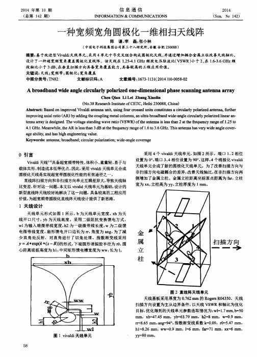
摘要 : 基 于改进型 Ⅵv a 1 d i 天线单元 , 采用 4单元十字交叉组合构成 圆极化天线 , 并通过 增加耦合金属立柱改善 天线轴 比, 设计 了一种超 宽频 宽角覆盖 圆极化直线 阵。该天线在 1 . 2 5 . 4 . 1 G Hz 频段 电压驻波 比( VS WR) 小于2 , 在1 . 6 . 3 . 6 GH z频
基于超表面的超宽带隐身天线罩的仿真设计
现代电子技术Modern Electronics Technique2023年12月1日第46卷第23期Dec. 2023Vol. 46 No. 230 引 言频率选择表面(Frequency Selective Surface, FSS )是一种由周期性排列的金属片或任意几何形状的孔径元件组成的周期结构[1⁃2],因其具有独特的频率选择特性而引起研究者们的广泛关注,它广泛应用于空间滤波器[3]、偏振器[4]、隐身天线罩[5⁃6]。
在隐身领域,由于天线通常是强散射源,因此降低整个天线系统的雷达横截面(Radar Scattering Section, RCS )至关重要。
当外部电磁波照射天线系统时,将天线工作波段外的电磁信号反射到某些方向,缩减了天线的单站RCS 。
同时,FSS 天线罩对天线工作频率范围内的信号具有全传输特性,保证了工作频段内天线的正常通信。
然而,这种反射带外电磁波的方法仅适用于单站雷达,对于双站或多站雷达而言并没有较好的隐身效果。
近年来形成了一种结合FSS 和吸波器的设计思路,它被称为频率选择性吸波体(FSA )。
FSA 通常能够吸收带外的入射电磁波,并且由一个传输波段来传输通信信号。
FSA 的概念首先在文献[5]中被提到,它一般由两层结构组成,即上层的吸波结构和下层的FSS 结构。
上层的吸波结构通常由金属结构和损耗元件构成,下层的FSS 由孔径元件组成。
根据吸波波段与传输波段位置基于超表面的超宽带隐身天线罩的仿真设计熊 杰, 杨宝平(黄冈师范学院 物理与电信学院, 湖北 黄冈 438000)摘 要: 为了减小飞行器的多基站雷达散射截面,增加天线系统的隐身功能,提出一种基于超表面的超宽带隐身天线罩模型,该模型具有低频吸收、高频传输的特性。
提出的天线罩由位于上层的吸波结构和位于下层的频率选择结构组成。
上层由两个π型金属结构与工型金属结构组合而成,中间通过电阻元件连接,下层由“X ”字型周期缝隙结构组成,每个周期结构中一个电阻层结构对应4个“X ”字型FSS 结构。
219332006_超宽带太赫兹调频连续波成像技术
第 21 卷 第 4 期2023 年 4 月Vol.21,No.4Apr.,2023太赫兹科学与电子信息学报Journal of Terahertz Science and Electronic Information Technology超宽带太赫兹调频连续波成像技术胡伟东,许志浩*,蒋环宇,刘庆国,檀桢(北京理工大学毫米波与太赫兹技术北京市重点实验室,北京100081)摘要:太赫兹调频连续波成像技术具有高功率、小型化、低成本、三维成像等特点,在太赫兹无损检测领域受到了广泛关注。
然而由于微波及太赫兹器件限制,太赫兹信号带宽难以做大,从而制约了成像的距离向分辨力。
虽然高载频可实现较大宽带,但伴随的低穿透性和低功率会限制太赫兹调频连续波成像系统的应用场景。
因此,聚焦于太赫兹波无损检测领域,提出一种时分频分复用的114~500 GHz超宽带太赫兹信号的产生方式,基于多频段共孔径准光设计,实现超带宽信号的共孔径,频率可扩展至1.1 THz。
提出一种频段融合算法,实现了超宽带信号的有效融合,距离分辨力提升至460 μm,通过人工设计的多层复合材料验证了系统及算法的有效性,并得到封装集成电路(IC)芯片的高分辨三维成像结果。
关键词:太赫兹调频连续波;非线性度校准;多频段融合;准光设计;无损检测中图分类号:TN914.42文献标志码:A doi:10.11805/TKYDA2022225Ultra-wideband terahertz FMCW imaging technologyHU Weidong,XU Zhihao*,JIANG Huanyu,LIU Qingguo,TAN Zhen (Beijing Key Laboratory of Millimeter Wave and Terahertz Technology,Beijing Institute of Technology,Beijing 100081,China)AbstractAbstract::Terahertz Frequency Modulated Continuous Wave(THz FMCW) imaging technology has attracted extensive attention in the field of THz Nondestructive Testing(NDT) because of its high power,miniaturization, low cost, three-dimensional imaging and other characteristics. However, due to thelimitation of microwave and terahertz devices, the terahertz signal bandwidth is difficult to expand, whichrestricts the range resolution of imaging. Although high carrier frequency can achieve large broadband,the accompanying low penetrability and low power will limit the application scenario of THz FMCWimaging system. Therefore, focusing on the field of terahertz wave nondestructive testing, this paperproposes a time-division frequency-division multiplexing 114~500 GHz ultra-wideband terahertz signalgeneration method, which is based on the quasi-optical design of multiband common aperture to achievethe common aperture of ultra-wideband signals. In addition, a multiband fusion algorithm is proposed toachieve effective fusion of ultra-wideband signals, and the range resolution is improved to 460 μm. Theeffectiveness of the system and algorithm is verified by artificially designed multilayer compositematerials, and the high-resolution 3D imaging results of Integrated Circuit(IC) chips are obtained.KeywordsKeywords::Terahertz Frequency Modulated Continuous Wave;non-linearity calibration;multiband fusion;quasi-optical design;Nondestructive Testing太赫兹波(0.03 mm~3 mm)在电磁波谱中位于微波与红外之间,由于其独特的穿透性与非电离性等特性,太赫兹技术已成功用于艺术品保护、工业产品质量控制、封装集成电路(IC)无损检测等领域[1-3]。
高增益宽带圆极化Vivaldi天线阵的设计
高增益宽带圆极化Vivaldi天线阵的设计许唐红;张弘;王东;朱海涛;兰敏【期刊名称】《强激光与粒子束》【年(卷),期】2013(025)003【摘要】提出了一种由新型Vivaldi天线单元构成的2×2十字交叉圆极化天线阵.Vivaldi天线单元采用边缘渐变对拓的锯齿结构,提高了天线在4.7~7.0 GHz频带内的增益,其反射系数低于-10 dB的带宽为2.4~11.0 GHz,具有超宽带线极化特性.圆极化天线阵测量结果显示,在4.5~7.0 GHz频带范围内,其轴比均低于3 dB,且整个频带范围内增益达11~13 dBi.%A circularly polarized (CP) crossed antenna array with 2X2 elements based on a novel antipodal Vivaldi antenna is proposed. The Vivaldi antenna with tapering serrated structure at the edges, which is a ultra-wideband (UWB) linearly polarized antenna, has a high gain at 4. 7-7. 0 GHz, and a wide impedance bandwidth of 2. 4-11. 0 GHz when the reflection coefficient is smaller than -10 dB. The measured data of the antenna array show that the axial ratio is lower than 3 dB between 4. 5 GHz and 7. 0 GHz. A high antenna gain from 11 dBi to 13 dBi is also achieved at the whole bandwidth of the array. The proposed antenna element and array both own UWB and high-gain characteristics.【总页数】4页(P685-688)【作者】许唐红;张弘;王东;朱海涛;兰敏【作者单位】四川大学电子信息学院,成都610064;四川大学电子信息学院,成都610064;四川大学电子信息学院,成都610064;四川大学电子信息学院,成都610064;四川大学电子信息学院,成都610064【正文语种】中文【中图分类】TN82【相关文献】1.高增益低副瓣X波段宽带圆极化Vivaldi天线阵设计 [J], 吴文鹤;韦高;赵文奇;李文廷2.高增益宽带圆极化微带天线阵研究 [J], 黄迎春;张涛;张福顺3.基于单层线-圆极化转换聚焦超表面的宽带高增益圆极化天线设计 [J], 李唐景;梁建刚;李海鹏;牛雪彬;刘亚峤4.一种宽带高增益圆极化天线阵 [J], 石小林;黄迎春;孙全国5.基于人工电磁结构的宽带宽波束高增益圆极化微带天线阵 [J], 林家栋;柴晋飞;苏周;巫勇因版权原因,仅展示原文概要,查看原文内容请购买。
1-3ghz超宽带一分四威尔金森功分器设计的
1-3ghz超宽带一分四威尔金森功分器设计的英文版Design of a 1-3 GHz Ultra-Wideband 1-to-4 Wilkinson Power DividerIn the realm of microwave and millimeter-wave systems, the Wilkinson power divider is a crucial component that enables the efficient distribution of power among multiple ports. This article presents the design of a 1-to-4 Wilkinson power divider operating within the ultra-wideband frequency range of 1-3 GHz.Design Considerations:Bandwidth: The design must exhibit a wideband performance, covering frequencies from 1 GHz to 3 GHz.Isolation: High isolation between output ports is essential to minimize cross-talk and maximize power transfer efficiency.Insertion Loss: Minimizing insertion loss is crucial to maintain high power handling capability.Matching: Good impedance matching is necessary to avoid reflections and maximize power transfer.Design Approach:The Wilkinson power divider is based on the concept of quarter-wavelength transformers, which are used to match impedances and provide isolation between ports. The design involves careful consideration of the transformer's impedance, physical dimensions, and material selection.The transformer's impedance is chosen to match the characteristic impedance of the transmission line, ensuring maximum power transfer. The physical dimensions of the transformer are optimized for the desired frequency range, ensuring broadband performance. The selection of high-quality microwave materials, such as low-loss dielectrics and conductors, is essential to minimize insertion loss and maximize power handling.Results:The designed 1-to-4 Wilkinson power divider exhibits excellent performance within the 1-3 GHz frequency range. It demonstrates high isolation between output ports, low insertion loss, and good impedance matching. This design is suitable for use in microwave and millimeter-wave systems requiring efficient power distribution over a wideband frequency range.中文版1-3 GHz超宽带一分四威尔金森功分器设计在微波和毫米波系统中,威尔金森功分器是一个关键组件,它能够将功率有效地分配给多个端口。
冲激信号产生技术研究

冲激信号产生技术研究摘要冲激脉冲的产生技术分为两类:利用储能电路和高速开关的传统产生技术和利用周期信号傅立叶级数的傅立叶合成技术。
本文全面介绍了各种形式的产生方法及其目前所具备的技术水平。
分析比较了各类方法的优缺点以及在应用中所要注意的问题。
关键词: 宽带传输; 脉冲信号; 信号分析中图分类号:xxxxx文献标志码:x近年来超宽带信号(Ultra-Wideband Radar Signal)引起了广泛的关注.超宽带信号中很重要的一类是冲激信号(ImpulseSignal),它是一种脉宽极短的窄脉冲,同时具有极低的频谱分量和极大的相对带宽(η常接近 100%)。
冲激信号由于可以工作在比传统窄带雷达低得多的频段上却同时获得与微波雷达相当的高距离分辨力, 因此能够成功地运用于叶簇和地表穿透成像,又由于冲激信号可以激励出丰富的目标谐波响应分量, 故在探测隐身目标以及目标识别方面也有着重要的应用价值。
然而, 冲激信号所具有的极大瞬时相对带宽却给其产生造成了很大的困难, 且信号的性能也难以保证。
多年来, 冲激信号的产生成为超宽带技术的一个重要研究领域。
突破高性能冲激信号的产生技术, 将具有重大的学术意义和应用价值。
本文对各种冲激信号产生技术的实现方法及其目前所具备的技术水平进行了系统研究, 根据冲激脉冲产生技术的特点,将目前的各种方法划分为传统产生技术和傅立叶合成技术两大类,并深入分析了各类冲激信号产生技术的优势及其局限性。
需要指出的是,冲激信号根据其信号形式的不同可以分为3类:基带波(Baseband Waveform)、单周波(Monocycle)和多周波(Polycycle)。
基带波没有载频, 最大的谱分量在直流附近的低频端, 频谱幅度在有效频带内单调下降, 目前许多文献所称的无载频信(CarrierFreeWaveform)、非正弦波信号(Nonsinusoidal Wave)也都指的是这一类冲激信号;单周波是只有一个周期的正弦信号,理想的单周波谱峰位于f0处, 在3dB带宽内频谱比较平坦;多周波是具有多个周期的正弦信号, 由于超宽带信号的百分比带宽大于 25%, 因此作为冲激信号的多周波其周期数目介于 2~4之间。
超宽带Vivaldi天线单元及阵列设计
第11期 肀螬f SM 龛找*f MVol .15N o.il2020 年 11 月Journal of CAEIT Nov . 2020doi : 10. 3969/j . issn . 1673-5692. 2020. 11.006超宽带Vivaldi 天线单元及阵列设计史信荣、史劼2,熊洋洋\柯进、罗旭东1(1.广东省计量科学研究院广东省现代几何与力学计量技术重点实验室,广东广州51〇4〇5;2.中国工业互联网研究院,北京100110)摘要:文中设计了一种新型超宽带平衡对跖Vivaldi 天线单元和阵列。
研究分析了主要结构参数 对天线性能的影响,通过增加金属隔板、接地柱、减小天线剖面高度等方式,将天线单元的阻抗带宽由1.7个倍频程提升至5个倍频程。
该新型天线单元具有阻抗带宽较宽、结构尺寸小的特点,是一 种较为理想的超宽带阵列天线单元。
在单元优化的基础上,文中对8 x 8的超宽带天线阵列性能进 行了研究,结果表明该天线阵列具有良好的阻抗带宽和辐射性能。
关键词:超宽带;Vivaldi 天线;平衡对跖中图分类号:TN 98文献标志码:A文章编号:1673-5692(2020) 11-10654)5Design of Ultra-Wideband Wide-angle Scanning VivaldiAntenna and ArraySHI Xin-rong 1 , SHI Jie 2 , XIONG Yang -yang 1 ,KE Jin ' , LUO Xu -dong 1(1. Guangdong Institute of Metrology , Guangdong Provincial Key Laboratory of Modem Geometric and MechanicalMetrology Technology , Guangzhou 510405 ,China ;2. China Academy of Industrial Internet , Beijing 100036,China )Abstract : A novel ultra-wideband (UWB ) balanced antipodal Vivaldi antenna element and array withwide-angle scanning is designed . The influence of the main structural parameters on the antenna perform ance is analyzed . The impedance bandwidth of the antenna element is improved from 1. 7 octaves to 5 oc taves by adding metallic partitions , metallic poles and reducing the height of the antenna . The novel an tenna element not only has a wide impedance bandwidth , but also a smaller structure size . The length and width of the antenna element is only half of the wavelength corresponding to the highest frequency . It is an ideal UWB wide-angle scanning array antenna element . On the basis of element optimization , the performance of 8 x 8 UWB array is studied . The results show that the aiTay has a wide impedance band width and good radiation performance .Key words : ultra-wideband (UWB ) ; vivaldi antenna ; balanced antipodal〇引言阵列天线具有快速扫描、波束形状捷变、空间功 率合成的能力,广泛应用在卫星通信、遥感遥测等领域。
- 1、下载文档前请自行甄别文档内容的完整性,平台不提供额外的编辑、内容补充、找答案等附加服务。
- 2、"仅部分预览"的文档,不可在线预览部分如存在完整性等问题,可反馈申请退款(可完整预览的文档不适用该条件!)。
- 3、如文档侵犯您的权益,请联系客服反馈,我们会尽快为您处理(人工客服工作时间:9:00-18:30)。
Ultra-Wideband Radar Using Fourier Synthesized WaveformsGurnam Singh GillAbstract—Traditional methods of ultra-wideband(UWB)radar signal generation suffer from several disadvantages such as low antenna radiation efficiency and lack of accurate control of signal parameters like pulse shape,pulse repetition interval(PRI),and its spectrum.UWB signals can be generated by expanding the desired radar waveform in Fourier series and then synthesizing the waveform by generating the individual terms in the expansion from harmonically related oscillators.Signals thus produced overcome the disadvantages of traditional methods of UWB signal generation.In this paper,Fourier series based method for generation of complex amplitude coded waveforms is developed which can be used to generate time domain equivalent of Barker and other codes for application in radar and communication areas.In radar applications,these coded waveforms,with accurate and stable waveform parameters,shall allow pulse compression and coherent integration.The additional processing gain provided by these operations reduces the need for high peak power in radar transmitters which is one of the bottlenecks in the implementation of operational UWB radars.This paper also describes a UWB radar concept which in-corporates Fourier synthesized waveforms.Related digital signal processing issues are also discussed.I.I NTRODUCTIONO VER THE last several years there has been wide interest in large relative bandwidth signals[1]–[3].Relative bandwidth is defined as the ratio of absolute bandwidth of the signal to its center frequency.Various terms such as impulse, monocycle,baseband,nonsinusoidal,and carrier free have been used for these large relative bandwidth signals.The name “impulse”is derived from the Dirac delta function.Many sources do produce high voltage impulse,but the radiated signal looks less like an impulse because of the suppression of dc and low frequency components of the impulse by the antenna.The name monocycle implies transmission of a single cycle of sinusoid which has large relative bandwidth [4].The terms baseband and carrier-free refer to the fact that these signals do not have a carrier frequency associated with tely,all these terms have been put under the umbrella of ultra-wideband(UWB)signals.Signals are said to be UWB if their relative bandwidth is0.25or larger [3].Although all signals with wide relative bandwidths are classified as UWB,there are subtle but important differences among them depending upon their method of generation. Waveforms described in this paper are closer to baseband Manuscript received August5,1996;revised December6,1996.This work was funded by the Office of Naval Research.The author is with the Department of Electrical and Computer Engineering, Naval Postgraduate School,Monterey,CA93943-5121USA.Publisher Item Identifier S0018-9375(97)03699-5.and nonsinusoidal than to monocycle and are generated by summing the harmonics of the signal to be synthesized. Most of the significant advantages of UWB radar signals reported in the literature stem from their two characteristics, i.e.,low frequency components in the signal and their narrow pulse width.The low frequency components penetrate ground and foliage more easily and thus can be used for detection of targets hidden in foliage or underground.Low frequency components may also excite target resonances which may lead to detection of stealthy targets.Very narrow pulse widths givefine range resolution and intercept less clutter.The latter is a big advantage as in most situations the target detec-tion is limited by clutter.Fine range resolution will produce detailed target range profiles which can be used for target identification.It should be noted that conventional narrow band signals can achieve the same large absolute bandwidths at higher frequencies,for example,in the millimeter wave region,but they do not have the same propagation and target scattering characteristics as do the UWB signals of comparable bandwidth.Most of the UWB sources reported in the literature are impulse types which are implemented by Marx bank or similar techniques.The concept behind impulse generation is the storage of energy over a long period of time followed by its sudden release.If the release time is of the order of a nanosecond or less,the resulting signal will be UWB impulse. At the present time,the typical method of storing energy is capacitive,such as the Marx bank,and the release of energy is accomplished by switches such as spark gap,diode, laser actuated semiconductor,etc.The problem with these techniques are that a significant amount of energy of the waveform lies around zero frequency which cannot be radiated by antenna.Pulse shape and pulse repetition interval(PRI) cannot be precisely controlled.There is nofine control of spectrum to avoid interference with friendly receivers.The Fourier method of waveform generation overcomes these disadvantages of conventional impulse generation.This method can synthesize any periodic waveform(such as train of baseband pulses of approximately rectangular shape)by expanding the desired waveform by Fourier series,then gen-erating and transmitting the sinusoidal components obtained from Fourier series expansion.Thus,the signal is generated in the frequency domain by summing the relatively low power harmonics of the desired signal instead of generating it by a single high power source in the time domain[5], [6].The resulting signal,unlike traditional UWB signals, is truly baseband and free of carrier and it overcomes the0018–9375/97$10.00©1997IEEEdisadvantages of the former.Since the signal is produced by summation of sinusoids,its spectrum is well defined and controlled.Any frequency which may interfere with the friendly users of the spectrum may not be transmitted with a minimal effect on the transmitted waveform.Stability and accuracy of time domain waveform parameters,i.e., pulse shape,PRI depends upon the stability of frequency components which constitute the signal.The stability of these frequency components can be assured by deriving them from a stable master oscillator.Radar performance in the presence of noise depends upon the energy of the pulse(or the average power)which increases with the increasing pulse width.However,target detection in the presence of clutter requires narrow pulse width as clutter is proportional to pulse width.These two contradictory re-quirements are often satisfied by the use of pulse compression which allows long transmit pulses for larger amounts of pulse energy and narrow compressed pulses for low clutter and good range resolution.UWB radars can benefit significantly from the use of pulse compression as UWB waveforms have low average power.Therefore,in this paper the Fourier synthesis is extended to a generation of complex amplitude coded waveforms with which we can generate Barker-like codes. This capability will allow the use of pulse compression in UWB radars and the stability of waveform parameters will allow the coherent integration of UWB signals.Both these operations reduce the need for very large power sources which are required for conventional implementation of impulse type radars.In contrast to conventional waveform which are pulsed carrier,the UWB waveforms do not contain carrier.Therefore, it is not possible to define target motion induced Doppler frequency shift for UWB signals.Thus,DFT implemented Doppler processing used for detection of narrowband radar signals cannot be employed in the processing of UWB radar signals.However,the change in round trip time of target from pulse to pulse can be used directly in the time domain to integrate pulses,discriminate clutter,and determine target velocity.The success of time domain processing depends upon the stability of time domain parameters of the radar wave-form.Unlike most conventional methods,these parameters can be accurately controlled for Fourier synthesized waveforms. This paper describes the generation of coded and uncoded waveforms,gives a coherent UWB radar system concept for Fourier based waveforms,and also describes important signal processing concepts required for implementation.II.W A VEFORM G ENERATIONThis section describes the waveform generation for both uncoded and coded waveforms for UWB radar.A.Generation of Uncoded WaveformsThe Fourier series is normally used to decompose periodic signals into sinusoids.However,the Fourier series can also be used in reverse to synthesize a periodic signal by generating and transmitting sinusoidal components obtained from the Fourier series expansion of the desired radar waveform.The Fourier series expansion will contain infinite terms,however, the number of oscillators which can be realistically employed isfinite.Furthermore,the direct current(dc)component cannot be transmitted by antenna and thus should not be included in the waveform generation.With these constraints a desired periodic radar waveform can be writtenas(1)where is the fundamental angular frequency corresponding to the desired pulse repetitioninterval(3)where(4)250MHz,0.5ns,Fig.1.Schematic diagram of the transmitter.based on this expansion wouldrequire oscillators or active phase control.However if the expansion is performed for time symmetric case where time axis is in the center of pulse the expansion will contain only cosine terms.Thus the terms to generate the waveform will requireonlyterms as givenbyin the Fourier series method will depend upon the power requirements (which are important for signal to noise ratio considerations),the pulse shape,the pulse width,and the practical considerations of having a certain number of oscillators.A related technique to Fourier Series based waveform gen-eration is stepped frequency waveforms in which successive pulses are monotonically increased in frequency by frequency steps.Note that,however,each pulse is composed of a single carrier frequency.Thus the frequency stepped waveform uses multiple frequencies over a group of pulses as compared to the Fourier series method which uses multiple frequencies in each pulse.In the stepped frequency method the received pulses are combined in signal processing to achieve an effective wide bandwidth or,equivalently,narrow pulses.Both methods achieve a large bandwidth,one sequentially and the other si-multaneously.The purpose of the stepped frequency waveform is to increase the effective bandwidth without increasingtheFig.2.Fourier series based rectangular pulse train.instantaneous bandwidth which is not the case for the Fourier series method.A lower instantaneous bandwidth waveform has several advantages including a lower sampling rate and a lower number of samples to be processed.However detection of moving targets with the stepped frequency method causes some complications and the signal processing becomes more involved [6],[7].B.Generation of Coded WaveformsCoded (pulse compression)waveforms are used in conven-tional narrow band radars to increase the average power (for higher detection performance)and still retain the advantages of short pulse.Average power is particularly low in UWB waveforms due to very narrow pulse width.Thus,it is all the more important to employ coded waveforms to increase the average power in UWB radars.In conventional radars pulse compression waveforms are generated by phase coding the carrier (i.e.,0,”and 180”).Binary coded waveforms for UWB radar can begenerated instead by polarity coding of the pulse,i.e.,positive amplitude for“with sum of sinusoids from Fourier series expansionas(10)If consists of delta function sequences,then it can beeasily expressed in the form of(9).Coefficients,are then computedas.1)Generation of Continuous Coded Waveforms:A gen-eral periodic code sequence shown in Fig.3(a)can bemathematically representedas(12)wheredepending upon a specific code.The codehas.Differentiating both sidesof(a)(b)Fig.3.Continuous wave and pulsed code sequences.(12)onegets(14)wherecan be representedasRewriting the above equationas(20)(23)Fig.4.Barker code of length7.(25)(26)and(27),shown at the bottom of the next page.In principle,either of the two methods can be used forcoded waveform generation.The key difference is that thefirst method requires fewer oscillators and requires the use ofswitches whereas the second method does not requireswitchesbut requires a higher number of oscillators.In general,the first method will be more efficient in most situations,as it requires fewer oscillators.The second method is suitable for very high PRF waveforms.III.R ADAR I MPLEMENTATIONIn conventional narrowband radars,receiver,and processor are designed as matched filters,which is usually done in three steps,i.e.,IF filter is matched to short pulse,pulse compression is matched to long coded pulse,and Doppler processing is matched to groupofexperiences Doppler shift,given approximatelyby is wavelength of the carrier of the narrowband signal.Signal from a moving target and clutter from ground undergo different Doppler shifts due to their different radial velocities.This allows the separation of target signal from clutter by frequency discrimination which is usually done by taking the FFT of the returned signal from several pulses,known as Doppler processing in the radar literature.For UWB signals,Doppler effect cannot be represented by frequency shift as there is no carrier in these signals thus denying the use of traditional Doppler processing.However target range changes by small amount from one pulse to next due to target motion.Thus the time of arrival of target signal will also change from pulse to pulse (whereas arrival time of clutter from stationary ground will not change from pulse to pulse).This change in arrival time,as explained below,can be utilized to coherently integrate the target return over several pulses as well as discriminate clutter from the target signal.Assume a target moving with radialvelocitysecondsis,the resulting sum will notbuild up as is shown in Fig.6.However,if the returns from successive pulses are added together with a delayof(27)Fig.5.Block diagram of UWB radarsystem.Fig.6.Illustration for explanation of velocity processor.Since received signal is in digital format after being sampled and quantized with analog to digital converter,the velocity processing has to be done digitally too.This paragraph ex-plains the digital version of the velocity processing.Before processing is started,samples fromall(as shown in Fig.7)wherepulsesandrange bins for each pulse.It is assumed that pulse compression is already performed before the organization of the data.Although practical case of interest is detection of moving targets,but detection of stationary target will be considered momentarily.For target detection the returned signal from all the pulses within a coherent processing interval (CPI)is addedtogether to improve its signal to noise ratio.For stationary targets this is done by adding the signal from the same range bin number due to all the pulses in the CPI as the stationary target stays in the same range bin during the transmission and reception of all the pulses within the CPI.This implies the addition of columns in Fig.7.In contrast,a moving target changes range bins with pulses in a CPI and this change in range bin from one pulse to next is givenbyis intheth pulse it would appear in the binnumber givenby stands for the integer expression within the parenthesis.To integrate signal duetothe outputs in range bins given by the above expression will be added together.Fig.7shows range bins for a case where the target moves by one bin during the time between the pulses.Since target velocity is not known in advance,expected range of target velocities will be considered.For each velocity a different set of range bins from pulse-range bin matrix will be added together.For practical implementation,only finite numbers of velocity values within the expected range of target velocity will be considered.This is equivalent to forming parallel filters,each tuned to a different velocity.However,velocity processing in baseband radars is performed in the time domain as compared to Doppler processing in conventional narrowband radars which is performed in the frequency domain.IV.C ONCLUSIONThis paper describes Fourier synthesis based method for generation of amplitude coded baseband waveforms and an UWB radar implementation which uses this waveform.Inradar application these amplitude coded waveforms can be used to implement pulse compression techniques which in-creases signal energy without any loss of range resolution.Furthermore stability of parameters of Fourier synthesized waveform allows effective integration of pulses which further increases signal to noise ratio and the processing gain.These increases in gain reduce the required transmitter peak power which is one of the bottlenecks in implementation of medium or long range operational UWB radars.R EFERENCES[1]H.F.Harmuth,Nonsinusoidal Waves for Radar and Radio Communica-tion.New York:Academic,1981.[2]J.D.Taylor,Introduction to Ultra-Wideband Radar Systems.BocaRaton,FL:CRC,1995.[3] B.Noel,Ultra-Wideband Radar:Proceedings of the First Los AlamosSymposium.Boca Raton,FL:CRC,1991.[4]M.I.Skolnik,“An introduction to impulse radar,”NRL Tech.Rep.6755,Nov.1990.[5]R.Tang and K.Lee,“An ultrawide band adaptive transmitter forultrawide band radar feasibility demonstration,”in Ultrawide Radar,Haie,Ed.Bellingham,WA:SPIE,1992,p.1631.[6]J. D.Taylor,Ultra-wideband Radar Technology and Applications.Boca Raton,FL:CRC,to be published.[7]G.S.Gill,“Step frequency waveform design and processing for detec-tion of moving targets,”in Int.Conf.Proc.IEEE ,June1995.Gurnam Singh Gill received the B.Sc.degree from Panjab University,India,the M.Tech.degree from the Indian Institute of Technology,New Delhi,In-dia,and the Ph.D.degree from Southern Methodist University,Dallas,TX,all in electrical engineering.During most of his career he performed R&D with defense contractors in the areas of radar,elec-tronic warfare,and communications.For the last seven years he has been teaching at Naval Postgrad-uate School,Monterey,CA,where he developed courses in airborne radars and high resolution radarsand is also involved in research in radar related topics.。