SSP206 Allradtriebe mit Haldex- Kupplung de
TE Connectivity 2.5 SDL Signal Double Lock 连接系统说明书

1 of 16© 2017 TE Connectivity Ltd. family of companies. PRODUCT INFORMATION 1-800-522-6752 All Rights Reserved. *Trademark.This controlled document is subject to change. For latest revision and Regional Customer Service, visit our website at . Signal Double Lock (2.5 SDL) Connector System1.SCOPE1.1.ContentThis specification defines performance, tests, and quality requirements for the Signal Double Lock (2.5 SDL) connector system.1.2. QualificationWhen tests are performed on the subject product line, procedures specified in Figure 1 shall be used. All inspections shall be performed using the applicable inspection plan and product drawing.2. APPLICABLE DOCUMENTSThe following documents form a part of this specification to the extent specified herein. Unless otherwise specified, the latest edition of the document applies. In the event of conflict between the requirements of this specification and the product drawing, the product drawing shall take precedence. In the event of conflict between the requirements of this specification and the referenced documents, this specification shall take precedence.2.1. TE Connectivity (TE) Documents108-5459-8 Restricted Product Specification – Signal Double Lock (2.5 SDL) Connector System108-5459-10 Restricted Product Specification – Signal Double Lock (2.5 SDL) Connector System108-5459-11 Restricted Product Specification – Signal Double Lock (2.5 SDL) Connector System114-5203 Application Specification – Signal Double Lock (2.5 SDL) Connector System 501-5223 Qualification Test Report – Signal Double Lock (2.5 SDL) Connector Hi-Pro Header501-5224 Qualification Test Report – Signal Double Lock (2.5 SDL) Connector Standard Header501-5230 Qualification Test Report – Signal Double Lock (2.5 SDL) Connector Wire to Wire Application502-106179Engineering Report – Signal Double Lock (2.5 SDL) Connector Withstanding Voltage Test2.2. Industry DocumentsEIA-364Electrical Connector Test Procedures Including Environmental Classifications IEC 60068 International Standard – Environmental Testing Procedures IEC 60335 International Standard – Safety of Household and Similar Appliance IEC 60512 International Standard – Connectors for Electronic Equipment – Tests and MeasurementsIEC 61984 International Standard – Safety Requirements and Tests2.3. Reference Documents109-1General Requirements for Testing109-35 Contact Engaging and Separating Force Test ProcedureTEC-109-11 Solderability Dip Test Procedure3. REQUIREMENTS3.1. Design and ConstructionProduct shall be of the design, construction, and physical dimensions specified on the applicableproduct drawing.3.2. MaterialsMaterials used in the construction of this product shall be as specified on the applicable productdrawing.A. Receptacle Contact and Tab Contact (Crimp): Pre-Tin Phosphor Bronze (Tin plating thickness: 0.8μm minimum)B. Plug and Cap Housing:6/6 Nylon (UL 94V-0). Tracking Index: 600 V (minimum)6/6 Nylon (Glass Filled 20%, UL 94V-0). Tracking Index: 250 – 399 VC. Double Lock Plate: 6/6 Nylon (Glass Filled 20%, UL 94V-0). Tracking Index: 250 – 399 VD. Header Assembly, Header Housing: 6/6 Nylon (Glass Filled 20%, UL 94V-0). Tracking Index:250 – 399 VE. Header Assembly, Post Contact: Tin Plated Brass (Tin plating thickness: 0.8 μm minimum)3.3. RatingsA. Voltage: 250 VACB.Figure 1C. Temperature: –30°C to 105°C (include temperature rise due to energized current)D. Minimum Rating: 1mV, 1μA (minimum)E. PCB RequirementsThickness: 1.6 mmDiameter of Thru Hole, for Tine: 0.9±0.05 mm (punched hole), 1.1±0.05 mm (drilled hole)Diameter of Thru Hole, for Boss: 1.7±0.05 mm (punched & drilled hole)3.4. Performance and Test DescriptionProduct is designed to meet the electrical, mechanical, and environmental performance requirements specified in Figure 2Figure 1. Unless otherwise specified, all tests shall be performed at ambientenvironmental conditions.3.5. Test Requirements and Procedures SummaryElectricalMechanicalFigure 2 (continued)EnvironmentalNOTEShall meet visual requirements, show no physical damage, and meet requirements of additional tests as specified in the product qualification and re-qualification test sequence given in Figure 8.Figure 2 (end)Power SourceLow Level Contact ResistancePCBAttach ThermocoupleHereFigure 3: Wire to Board Connector Set-up for Low Level Contact Resistanceand Temperature Rise vs. Current TestingAttach ThermocoupleHereAttach ThermocoupleHereLow Level Contact ResistancePower SourceFigure 4: Wire to Wire Connector Set-up for Low Level Contact Resistance and TemperatureRise vs. Current TestingSecuredWireConnector Mounting TableVibration TableWire to Wire ConnectorWire to Board ConnectorWireSecuredConnector Mounting TableFigure 5: Connector Mounting Method for Sinusoidal Vibration and Physical Shock TestsTest Specimen (Connector)PC Board Hammer Weight (Striking Frequency: 1 stroke/second)Hammer (50g Steel Weight)Spacer Sample Mounting Fixture Rubber StandDetail A Detail B Figure 7: Gage Design for Contact Mating/Unmating Force Test3.6. Product Qualification and Re-Qualification Test SequenceFigure 8 (continued)NOTE(a) See paragraph 4.1.A.(b) Numbers indicate sequence in which tests are performed.Figure 8 (end)4. QUALITY ASSURANCE PROVISIONS4.1. Qualification TestingA. Specimen SelectionSpecimens shall be prepared in accordance with applicable instruction sheets and shall be selected at random from current production. The wires crimped to the contacts must meet the requirements inFigure 9.Figure 9B. Test SequenceQualification inspection shall be verified by testing specimens as specified in Figure 8.4.2. Re-Qualification TestingIf changes that significantly affecting form, fit, or function are made to the product or manufacturing process, product assurance shall coordinate re-qualification testing consisting of all or part of theoriginal testing sequence as determined by development/product, quality, and reliability engineering.4.3. AcceptanceAcceptance is based on verification that the product meets the requirements of Figure 2. Failuresattributed to equipment, test setup, or operator deficiencies shall not disqualify the product. If product failure occurs, corrective action shall be taken and specimens re-submitted for qualification. Testing to confirm corrective action is required before re-submittal.4.4. Quality Conformance InspectionThe applicable quality inspection plan shall specify the sampling acceptable quality level to be used.Dimensional and functional requirements shall be in accordance with the applicable product drawing and this specification.APPENDIXThe applicable product descriptions and base numbers are shown in Figure 10.Figure 10。
Extreme Networks SLX 9640高性能固定路由器商品介绍说明书

ExtremeRouting? SLX 9640
Built to Suit Your Business Needs Ext rem e Elem ent s are t he b uild ing b locks t hat allow you t o t ailor your net w ork t o your sp ecific b usiness environm ent , g oals, and ob ject ives. They enab le t he creat ion of an A ut onom ous Net w ork t hat d elivers t he p osit ive exp eriences and b usiness out com es m ost im p ort ant t o your org anizat ion.
W W W.EXTREMENETW
1
Flexib le Bo rd er Ro ut ing w it h Int ernet Scale, Ult ra-Deep Buffers,
MPLS and EVPN
The SLX 964 0 is a very p ow erful com p act d eep b uffer Int ernet b ord er rout er, p rovid ing a cost -efficient solut ion t hat is p urp ose-b uilt for t he m ost d em and ing service p rovid er and ent erp rise d at a cent ers and MA N/ WA N ap p licat ions. The rob ust syst em archit ect ure sup p ort ed by SLX-OS and a versat ile feat ure set includ ing IPv4 , IPv6, and MPLS/ VPLS w it h Carrier Et hernet 2.0 and OA M cap ab ilit ies t o p rovid e d ep loym ent flexib ilit y.
紧急停止按钮指南说明书

05.2020ContactSchmersal USA 15 Skyline DriveHawthorne, NY 10532 Tel: 914-347-4775 Fax: 914-347-1567E -mail:**********************Schmersal Canada29 Centennial Road, Unit 1 Orangeville, ON L9W 1R1 Tel: 519-307-7540 Fax: 519-307-7543E -Mail:*************************Tech Briefs:Emergency Stop ButtonsWhitepaper:Emergency Stop DevicesVisit our website for a PDF CopyOverviewAccording to OSHA, ANSI and relevant ISO regulations every machine is required to have a means to immediately remove all hazardous energy in the event of an emergency. In most all industrial machines this is achieved by the use of an Emergency Stop (E -Stop) pushbutton.NFPA79 and ISO 13850 detail the physical characteristics of a push button E -Stop, which will include a RED mushroom operator head with YELLOW background. It must also be self -latching, meaning that once actuated the Emergency Stop will remain in the actuated state until a voluntary and deliberate action is performed, such as twisting and/or pulling of the palm button for reset. In addition, this resetting of the E -Stop alone should not resume operation; instead a second deliberate action is needed, such as the pressing of a RESET button.OSHA and standards such as IEC 60204-1 state that an Emergency Stop must be readily accessible to the operator. This means that every operator station or any area of the machine worked on which is considered part of the normal operating procedure needs a means for an emergency stop. It should be unobstructed and easily accessible without having to reach over, under or around to actuate.BDF100-NHK -G -ST E -STOP 201 ESTOP -MBGAC311 Various ModelsSchmersal offers a number of complete E -Stop pushbutton kits that satisfy all relevant require-ments. They include the operator, contact blocks, and enclosure.BDF100-NH -G -STE -Stop without protective collarBDF100-NHK -G -STE -Stop with protective collarE -STOP201Plastic pushbutton in plastic enclosure (pre -assembled)ADRR40RT 40mm button CLP101 1NC contact (x2) MBKAC311YE EnclosureAdditional contact blocks available: CLP101 1NC contact CLP110 1NO contactE -STOP -MBGAC311 Metal pushbutton in metal enclosure (kit)EDRR50RT 50mm button EF220.1 2NC contact EFR Spring element MBGAC311YE EnclosureAdditional contact blocks available: EF220.2 2NC EF303.2 1NO/1NCE -STOP KITMetal pushbutton for panel mounting (kit)EDRR40RT 40mm button EF303.1 1NO/1NC contact EF303.2 1NO/1NC contact EFR Spring Element MDP8.2 Yellow plateCompatible Safety Controllers SRB -E -201LC SRB -E -322ST SRB -E -201ST SRB -E -402ST SRB -E -301ST SRB -301MC SRB -E -212STE -STOP KITAvailable LiteratureCommand and Signaling Devices Complete E -STOP KITThe E -STOP KIT includes all the components necessary for a panel -mounted emergency stop pushbutton. They are delivered in a single box.It includes:A 40 mm diameter aluminum operator head with mounting block.Two 1 NO & 1 NC contact blocks.A spring element for latching and reset function.A round yellow metal plate with adhesive on the back.IP69K Rated E -StopSchmersal offers an E -Stop pushbutton that meets IP69K sealing requirements … tolerating high temperature (up to 175°F) steam or water wash downs at pressures up to 1450 psi. The NDRR50RT offers a 50 mm wide, thermoplastic head and modular contact block system.This E -Stop is ideal for applications where hygienic conditions are critical (food processing, medical equipment, meat packaging and pharmaceutical manufacturing). It was specifically designed with smooth surfaces to reduce the accumulation of process substances, dirt and/or bacteria.。
AT28HC64B高性能电擦可编程只读存储器(EEPROM)说明书

Features Array•Fast Read Access Time – 70 ns•Automatic Page Write Operation–Internal Address and Data Latches for 64 Bytes•Fast Write Cycle Times–Page Write Cycle Time: 10 ms Maximum (Standard)2 ms Maximum (Option – Ref. AT28HC64BF Datasheet)–1 to 64-byte Page Write Operation•Low Power Dissipation–40 mA Active Current–100µA CMOS Standby Current•Hardware and Software Data Protection•DATA Polling and Toggle Bit for End of Write Detection•High Reliability CMOS Technology–Endurance: 100,000 Cycles–Data Retention: 10 Years•Single 5 V ±10% Supply•CMOS and TTL Compatible Inputs and Outputs•JEDEC Approved Byte-wide Pinout•Industrial Temperature Ranges•Green (Pb/Halide-free) Packaging Option Only1.DescriptionThe AT28HC64B is a high-performance electrically-erasable and programmable read-only memory (EEPROM). Its 64K of memory is organized as 8,192 words by 8 bits. Manufactured with Atmel’s advanced nonvolatile CMOS technology, the device offers access times to 55 ns with power dissipation of just 220 mW. When the device is deselected, the CMOS standby current is less than 100µA.The AT28HC64B is accessed like a Static RAM for the read or write cycle without the need for external components. The device contains a 64-byte page register to allow writing of up to 64 bytes simultaneously. During a write cycle, the addresses and 1 to 64 bytes of data are internally latched, freeing the address and data bus for other operations. Following the initiation of a write cycle, the device will automatically write the latched data using an internal control timer. The end of a write cycle can be detected by DATA polling of I/O7. Once the end of a write cycle has been detected, a new access for a read or write can begin.Atmel’s AT28HC64B has additional features to ensure high quality and manufactura-bility. The device utilizes internal error correction for extended endurance and improved data retention characteristics. An optional software data protection mecha-nism is available to guard against inadvertent writes. The device also includes anextra 64 bytes of EEPROM for device identification or tracking.20274L–PEEPR–2/3/09AT28HC64B2.Pin Configurations2.128-lead SOIC Top ViewPin Name Function A0 - A12Addresses CE Chip Enable OE Output Enable WE Write Enable I/O0 - I/O7Data Inputs/Outputs NC No Connect DCDon’t Connect2.232-lead PLCC Top ViewNote:PLCC package pins 1 and 17 are Don’t Connect.2.328-lead TSOP Top View30274L–PEEPR–2/3/09AT28HC64B3.Block Diagram4.Device Operation4.1ReadThe AT28HC64B is accessed like a Static RAM. When CE and OE are low and WE is high, the data stored at the memory location determined by the address pins is asserted on the out-puts. The outputs are put in the high-impedance state when either CE or OE is high. This dual line control gives designers flexibility in preventing bus contention in their systems.4.2Byte WriteA low pulse on the WE or CE input with CE or WE low (respectively) and OE high initiates a write cycle. The address is latched on the falling edge of CE or WE, whichever occurs last. The data is latched by the first rising edge of CE or WE. Once a byte write has been started, it will automatically time itself to completion. Once a programming operation has been initiated and for the duration of t WC , a read operation will effectively be a polling operation.4.3Page WriteThe page write operation of the AT28HC64B allows 1 to 64 bytes of data to be written into the device during a single internal programming period. A page write operation is initiated in the same manner as a byte write; after the first byte is written, it can then be followed by 1 to 63 additional bytes. Each successive byte must be loaded within 150 µs (t BLC ) of the previous byte. If the t BLC limit is exceeded, the AT28HC64B will cease accepting data and commence the internal programming operation. All bytes during a page write operation must reside on the same page as defined by the state of the A6 to A12 inputs. For each WE high-to-low transition during the page write operation, A6 to A12 must be the same.The A0 to A5 inputs specify which bytes within the page are to be written. The bytes may be loaded in any order and may be altered within the same load period. Only bytes which are specified for writing will be written; unnecessary cycling of other bytes within the page does not occur.4.4DATA PollingThe AT28HC64B features DATA Polling to indicate the end of a write cycle. During a byte or page write cycle, an attempted read of the last byte written will result in the complement of the written data to be presented on I/O7. Once the write cycle has been completed, true data is valid on all outputs, and the next write cycle may begin. DATA Polling may begin at any time during the write cycle.40274L–PEEPR–2/3/09AT28HC64B4.5Toggle BitIn addition to DATA Polling, the AT28HC64B provides another method for determining the end of a write cycle. During the write operation, successive attempts to read data from the device will result in I/O6 toggling between one and zero. Once the write has completed, I/O6 will stop toggling, and valid data will be read. Toggle bit reading may begin at any time during the write cycle.4.6Data ProtectionIf precautions are not taken, inadvertent writes may occur during transitions of the host system power supply. Atmel ® has incorporated both hardware and software features that will protect the memory against inadvertent writes.4.6.1Hardware ProtectionHardware features protect against inadvertent writes to the AT28HC64B in the following ways: (a) V CC sense – if V CC is below 3.8 V (typical), the write function is inhibited; (b) V CC power-on delay – once V CC has reached 3.8 V, the device will automatically time out 5 ms (typical) before allowing a write; (c) write inhibit – holding any one of OE low, CE high or WE high inhib-its write cycles; and (d) noise filter – pulses of less than 15 ns (typical) on the WE or CE inputs will not initiate a write cycle.4.6.2Software Data ProtectionA software-controlled data protection feature has been implemented on the AT28HC64B. When enabled, the software data protection (SDP), will prevent inadvertent writes. The SDP feature may be enabled or disabled by the user; the AT28HC64B is shipped from Atmel with SDP disabled.SDP is enabled by the user issuing a series of three write commands in which three specific bytes of data are written to three specific addresses (refer to the “Software Data Protection Algorithm” diagram on page 10). After writing the 3-byte command sequence and waiting t WC , the entire AT28HC64B will be protected against inadvertent writes. It should be noted that even after SDP is enabled, the user may still perform a byte or page write to the AT28HC64B. This is done by preceding the data to be written by the same 3-byte command sequence used to enable SDP.Once set, SDP remains active unless the disable command sequence is issued. Power transi-tions do not disable SDP, and SDP protects the AT28HC64B during power-up and power-down conditions. All command sequences must conform to the page write timing specifica-tions. The data in the enable and disable command sequences is not actually written into the device; their addresses may still be written with user data in either a byte or page write operation.After setting SDP, any attempt to write to the device without the 3-byte command sequence will start the internal write timers. No data will be written to the device, however. For the dura-tion of t WC , read operations will effectively be polling operations.4.7Device IdentificationAn extra 64 bytes of EEPROM memory are available to the user for device identification. By raising A9 to 12 V ±0.5 V and using address locations 1FC0H to 1FFFH, the additional bytes may be written to or read from in the same manner as the regular memory array.50274L–PEEPR–2/3/09AT28HC64BNotes:1.X can be VIL or VIH.2.See “AC Write Waveforms” on page 8.3.VH = 12.0 V ±0.5 V.Note:1.I SB1 and I SB2 for the 55 ns part is 40 mA maximum.5.DC and AC Operating RangeAT28HC64B-70AT28HC64B-90AT28HC64B-120Operating Temperature (Case)-40°C - 85°C -40°C - 85°C -40°C - 85°C V CC Power Supply5 V ±10%5 V ±10%5 V ±10%6.Operating ModesMode CE OE WE I/O Read V IL V IL V IH D OUT Write (2)V IL V IH V IL D IN Standby/Write Inhibit V IH X (1)X High ZWrite Inhibit X X V IH Write Inhibit X V IL X Output Disable X V IH XHigh ZChip Erase V ILV H (3)V IL High Z7.Absolute Maximum Ratings*Temperature Under Bias................................-55°C to +125°C *NOTICE:Stresses beyond those listed under “Absolute Maximum Ratings” may cause permanent dam-age to the device. This is a stress rating only and functional operation of the device at these or any other conditions beyond those indicated in the operational sections of this specification is not implied. Exposure to absolute maximum rating conditions for extended periods may affect device reliabilityStorage Temperature.....................................-65°C to +150°C All Input Voltages(including NC Pins)with Respect to Ground.................................-0.6 V to +6.25 V All Output Voltageswith Respect to Ground...........................-0.6 V to V CC + 0.6 V Voltage on OE and A9with Respect to Ground..................................-0.6 V to +13.5V8.DC CharacteristicsSymbol Parameter ConditionMinMax Units I LI Input Load Current V IN = 0 V to V CC + 1 V 10µA I LO Output Leakage Current V I/O = 0 V to V CC10µA I SB1V CC Standby Current CMOS CE = V CC - 0.3 V to V CC + 1 V 100(1)µA I SB2V CC Standby Current TTL CE = 2.0 V to V CC + 1 V 2(1)mA I CC V CC Active Current f = 5 MHz; I OUT = 0 mA40mA V IL Input Low Voltage 0.8V V IH Input High Voltage 2.0V V OL Output Low Voltage I OL = 2.1 mA 0.40V V OH Output High VoltageI OH = -400 µA2.4V60274L–PEEPR–2/3/09AT28HC64B10.AC Read Waveforms (1)(2)(3)(4)Notes:1.CE may be delayed up to t ACC - t CE after the address transition without impact on t ACC .2.OE may be delayed up to t CE - t OE after the falling edge of CE without impact on t CE or by t ACC - t OE after an address changewithout impact on t ACC .3.t DF is specified from OE or CE whichever occurs first (C L = 5 pF).4.This parameter is characterized and is not 100% tested.9.AC Read CharacteristicsSymbol ParameterAT28HC64B-70AT28HC64B-90AT28HC64B-120Units MinMax MinMax MinMax t ACC Address to Output Delay 7090120ns t CE (1)CE to Output Delay 7090120ns t OE (2)OE to Output Delay 035040050ns t DF (3)(4)OE to Output Float 035040050ns t OHOutput Hold00ns70274L–PEEPR–2/3/09AT28HC64B11.Input Test Waveforms and Measurement Level12.Output Test LoadNote:1.This parameter is characterized and is not 100% tested.R F 13.Pin Capacitancef = 1 MHz, T = 25°C (1)Symbol Typ Max Units Conditions C IN 46pF V IN = 0 V C OUT 812pFV OUT = 0 V815.AC Write Waveforms15.1WE Controlled15.2CE Controlled14.AC Write CharacteristicsSymbol ParameterMin MaxUnits t AS , t OES Address, OE Setup Time 0ns t AH Address Hold Time 50ns t CS Chip Select Setup Time 0ns t CH Chip Select Hold Time 0ns t WP Write Pulse Width (WE or CE)100ns t DS Data Setup Time 50ns t DH , t OEHData, OE Hold Timens90274L–PEEPR–2/3/09AT28HC64B17.Page Mode Write Waveforms (1)(2)Notes: 1.A6 through A12 must specify the same page address during each high to low transition of WE (or CE).2.OE must be high only when WE and CE are both low.18.Chip Erase Waveformst S = t H = 5 µs (min.)t W = 10 ms (min.)V H = 12.0 V ±0.5 V16.Page Mode CharacteristicsSymbol Parameter MinMax Units t WC Write Cycle Time10ms t WC Write Cycle Time (Use AT28HC64BF))2ms t AS Address Setup Time 0ns t AH Address Hold Time 50ns t DS Data Setup Time 50ns t DH Data Hold Time 0ns t WP Write Pulse Width 100ns t BLC Byte Load Cycle Time 150µs t WPHWrite Pulse Width High50ns100274L–PEEPR–2/3/09AT28HC64B19.Software Data Protection EnableAlgorithm (1)Notes:1.Data Format: I/O7 - I/O0 (Hex);Address Format: A12 - A0 (Hex).2.Write Protect state will be activated at end of writeeven if no other data is loaded.3.Write Protect state will be deactivated at end of writeperiod even if no other data is loaded.4.1 to 64 bytes of data are loaded.20.Software Data Protection DisableAlgorithm (1)Notes:1.Data Format: I/O7 - I/O0 (Hex);Address Format: A12 - A0 (Hex).2.Write Protect state will be activated at end of writeeven if no other data is loaded.3.Write Protect state will be deactivated at end of writeperiod even if no other data is loaded.4. 1 to 64 bytes of data are loaded.21.Software Protected Write Cycle Waveforms (1)(2)Notes:1.A6 through A12 must specify the same page address during each high to low transition of WE (or CE) after the softwarecode has been entered.2.OE must be high only when WE and CE are both low.11AT28HC64BNote:1.These parameters are characterized and not 100% tested. See “AC Read Characteristics” on page 6.23.Data Polling WaveformsNotes:1.These parameters are characterized and not 100% tested.2.See “AC Read Characteristics” on page 6.25.Toggle Bit Waveforms (1)(2)(3)Notes: 1.Toggling either OE or CE or both OE and CE will operate toggle bit.2.Beginning and ending state of I/O6 will vary.3.Any address location may be used, but the address should not vary.22.Data Polling Characteristics (1)Symbol Parameter Min TypMaxUnits t DH Data Hold Time 0ns t OEH OE Hold Time 0ns t OE OE to Output Delay (1)ns t WR Write Recovery Timens24.Toggle Bit Characteristics (1)Symbol Parameter Min TypMaxUnits t DH Data Hold Time 10ns t OEH OE Hold Time 10ns t OE OE to Output Delay (2)ns t OEHP OE High Pulse 150ns t WR Write Recovery Timens12AT28HC64B26.Normalized I CCGraphs13AT28HC64B27.Ordering Information27.1Green Package Option (Pb/Halide-free)t ACC (ns)I CC (mA)Ordering Code Package Operation RangeActive Standby 70400.1AT28HC64B-70TU 28T Industrial (-40°C to 85°C)AT28HC64B-70JU 32J AT28HC64B-70SU 28S 90400.1AT28HC64B-90JU 32J AT28HC64B-90SU 28S AT28HC64B-90TU 28T 120400.1AT28HC64B-12JU 32J AT28HC64B-12SU28SPackage Type32J 32-lead, Plastic J-leaded Chip Carrier (PLCC)28S 28-lead, 0.300" Wide, Plastic Gull Wing Small Outline (SOIC)28T28-lead, Plastic Thin Small Outline Package (TSOP)27.2Die ProductsContact Atmel Sales for die sales options.28.Packaging Information 28.132J – PLCC14AT28HC64BAT28HC64B 28.228S – SOIC1528.328T – TSOP16AT28HC64BHeadquarters InternationalAtmel Corporation 2325 Orchard Parkway San Jose, CA 95131 USATel: 1(408) 441-0311 Fax: 1(408) 487-2600Atmel AsiaUnit 1-5 & 16, 19/FBEA Tower, Millennium City 5418 Kwun Tong RoadKwun Tong, KowloonHong KongTel: (852) 2245-6100Fax: (852) 2722-1369Atmel EuropeLe Krebs8, Rue Jean-Pierre TimbaudBP 30978054 Saint-Quentin-en-Yvelines CedexFranceTel: (33) 1-30-60-70-00Fax: (33) 1-30-60-71-11Atmel Japan9F, Tonetsu Shinkawa Bldg.1-24-8 ShinkawaChuo-ku, Tokyo 104-0033JapanTel: (81) 3-3523-3551Fax: (81) 3-3523-7581Product ContactWeb SiteTechnical Support******************Sales Contact/contactsLiterature Requests/literatureDisclaimer: The information in this document is provided in connection with Atmel products. No license, express or implied, by estoppel or otherwise, to any intellectual property right is granted by this document or in connection with the sale of Atmel products. EXCEPT AS SET FORTH IN ATMEL’S TERMS AND CONDI-TIONS OF SALE LOCATED ON ATMEL’S WEB SITE, ATMEL ASSUMES NO LIABILITY WHATSOEVER AND DISCLAIMS ANY EXPRESS, IMPLIED OR STATUTORY WARRANTY RELATING TO ITS PRODUCTS INCLUDING, BUT NOT LIMITED TO, THE IMPLIED WARRANTY OF MERCHANTABILITY, FITNESS FOR A PARTICULAR PURPOSE, OR NON-INFRINGEMENT. IN NO EVENT SHALL ATMEL BE LIABLE FOR ANY DIRECT, INDIRECT, CONSEQUENTIAL, PUNITIVE, SPECIAL OR INCIDEN-TAL DAMAGES (INCLUDING, WITHOUT LIMITATION, DAMAGES FOR LOSS OF PROFITS, BUSINESS INTERRUPTION, OR LOSS OF INFORMATION) ARISING OUT OF THE USE OR INABILITY TO USE THIS DOCUMENT, EVEN IF ATMEL HAS BEEN ADVISED OF THE POSSIBILITY OF SUCH DAMAGES. Atmel makes no representations or warranties with respect to the accuracy or completeness of the contents of this document and reserves the right to make changes to specifications and product descriptions at any time without notice. Atmel does not make any commitment to update the information contained herein. Unless specifically provided otherwise, Atmel products are not suitable for, and shall not be used in, automotive applications. Atmel’s products are not intended, authorized, or warranted for use as components in applications intended to support or sustain life.© 2009 Atmel Corporation. All rights reserved. Atmel®, logo and combinations thereof, and others are registered trademarks or trademarks of Atmel Corporation or its subsidiaries. Other terms and product names may be trademarks of others.。
Acura electro 926XS 936 956 微型微管多管电子管说明书

Última actualización de una exitosa línea que hace que el pipeteadoelectrónico sea más versátil, sencillo y seguro que nunca.Características de la Acura®electro :•Ergonomía optimizada, ligera •Programa de autoaprendizaje fácil e intuitivo•Gran display de visualización reversible para lectura izquierda /derecha •Batería rápidamente intercambiable •Carga rápida, gran autonomía de trabajo •Eyector ajustable* que se adapta a la mayoría de las puntas •Contador de ciclo de pipeteado •Módulos volumétricos intercambiables – todos se adaptan a la misma unidad de control.* Patentado por SocorexSu elección electrónicaModelos Acura® electro926XS 936956micro macro multimicropipetas electrónicasGran autonomía de trabajo El pack de batería NiMH se puede extraer y cambiar instantáneamente.Carga rápida de la batería (<1,5 horas) y gran autonomía de trabajo. (> 3000ciclos de pipeteado consecutivos). El nivel de carga de la batería se visualiza claramente en el display. Modo automático de ahorro de energía o stand-by cuando no se está utilizando.0.1 - 2 µl 0.5 - 10 µl 1 - 20 µl 2.5 - 50 µl 5 - 100 µl 10 - 200 µl 50 - 1000 µl0.1 - 2 ml 0.25 - 5 ml 0.5 - 10 mlVelocidad de pipeteado regulableEl selector de velocidad, situado en la parte frontal, permite un cambio inmediato de la velocidad incluso durante el proceso de pipeteado.Además, en cualquier momento, se puede activar la velocidad más baja pulsando el botón de puesta en marcha.Display exclusivo de visualización para zurdos o diestrosEl display pasa instantáneamente de la lectura hacia la derecha a la lectura hacia la izquierda. Toda la información se presenta claramente y es visible de un vistazo durante las etapas deprogramación, pipeteado y calibración.Ergonomía naturalLa pipeta Acura® electro ofrece una forma, un equilibrio y una ergonomía de trabajo semejantes a las de las pipetas manuales. Sin embargo se ha mejorado tanto la comodidad de uso,que el pipeteado y la coherencia de los resultados son excelentes.936macro926XSmicro2Ahorra espacio y permite cargar hasta tres baterías simultáneamente. El accesorio ideal para cargar y guardar baterías de recambio,0.5 - 10 µl 2.5 - 50 µl 10 - 200 µl 20 - 350 µlEl sonido puede ser activado/desactivado en cualquier momento.956multiÓptima posición de trabajo La rotación de 360° de los módulos volumétricos multicanal permiteseleccionar la mejor posición de trabajo.Eyección de la punta –más fácil que nuncaMayor eficacia del eyector de puntas gracias a un cómodo botón de eyección ergonómicamenteposicionado. El sistema de ajuste de la altura del eje patentado,llamado Justip TM (intervalo de 4 mm) y controlado mediante eficaces dispositivos de retención, permite utilizar una amplia gama de puntas que se ajustan a la boquilla a presión.La forma curvada de la cabeza del eyector en el modelo multicanal,permite una eyección de las puntas secuencial y sin esfuerzo.Contador de ciclo de pipeteado Un sencillo doble clic permite acceder al número de ciclos de pipeteadoefectuados desde la última puesta a cero.3Para modelos de 2 y 5 ml Para modelos de 10 ml250/pack 100/packPresent.322.05322.10Código Descripciónodos los modelos son esterilizables en autoclavable. Se ajustan de forma totalmente hermética en las pipetas Socorex y son extraordinariamente adaptables a otras marcas.4Protección eficiente frente a aerosoles. Incluyen un filtro de PE de alta densidad que permite la recuperación completa de muestrasno contaminadas. Certificación de ausencia de DNAsa y RNAsa. Las puntas estérilizades están garantizadas sin pirógeno.Filtros protección de boquillaPara modelos de 2 ml Para modelos de 5 ml1 / pack 1 / pack 1.835.6311.835.633CódigoDescripción Present.Adaptadores parapipetas PasteurTiempo de mantenimiento eficiente La construcción de la pipeta limita elmantenimiento al mínimo. No se necesita ninguna herramienta para retirar elmódulo volumétrico. El contador de ciclo de pipeteado facilita el seguimiento del mantenimiento. Cada vez que la esterilización sea necesaria, los módulos volumétricos pueden ser replazados y se pueden poner en un autoclave a 121°C / 250°F.Pack inicialRecomendado cuando se compra un Acura®electro por primera vez, cada pack inicial incluye: una pipeta electrónica, un certificado de Control de Calidad y un manual de instrucciones, un soporte cargador, fuente de alimentación, un pack de batería adicional y muestras de puntas de pipeta Qualitips®.Posteriormente se pueden comprar pipetas adicionales individualmente y cargarlas en el soporte existente.5CalibraciónEl software de control permite acceder inmediatamente al menú de calibración. La verificación del funcionamiento es posible sobre dos o tres volúmenes independientes (Vmin, Vmed y Vmax). Los nuevos ajustes se realizan directamente en el teclado del instrumento. Un mensaje de error avisa sobre cualquier movimiento inexacto del émbolo.Tono del tecladoEl sonido puede ser activado/desactivado en cualquier momento.•Modo avanzadoAspiración y pipeteado de un volumen fijo. Adecuado para todas las aplicaciones.•Modo reversibleAspiración en exceso seguida por la dosificación de un volumen fijo. Mejora la reproductibilidad por debajo de 20 µl. Especialmente recomendado para líquidos viscosos y espumosos.•Modo gradualLlenado de la punta y distribución gradual. Apropiado para muestras alícuotas.•Modo diluciónAspiración de 2 o 3 volúmenes diferentes para restitución en una sola inyección. Una manera fácil de diluir muestras.•Modo táctilIniciar y detener la medición del líquido, valorar y transferir gel con sólo pulsar un botón.•MezcladoFlujo de líquido “arriba y abajo” en la punta / vial.Las características de calibración de los módulos adicionales, fijadas por el control de calidad de fábrica o por el propietario de pipeta, quedan registradas en la memoria del instrumento.SOCOREX ISBA S.A.Champ Colomb 7, Casilla de correo 3781024 Ecublens / Lausanne SUIZA*******************Telf. +41 (0)21 651 6000Fax +41 (0)21 651 6001Normas y cumplimientoLas pipetas Acura® electro han sido diseñadas para funcionar conforme a normas nacionales e internacionales tales como EN ISO 8655, GMP ,GLP , NCCLS. Cumplen las siguientes normas:•IVD 98/79 ECC (dispositivosmédicos para diagnóstico in vitro)•ED 89/336 EEC, 91/263 EEC, 92/31EEC, 93/68 EEC, FCC-CFR47, part 15(compatibilidad electromagnética)•ED 73/23 EEC, 93/68 EEC, IEC 61010-1 (seguridad eléctrica)•ED 2011/65/EC Restricción de sustancias peligrosas (RoHS)Control calidad, seguridad y garantía Cada instrumento tiene asignado un número de serie y pasa un estricto control de calibración,garantizado por un certificado de control de calidad individual. Remítase a ladocumentación suministrada con el instrumento sobre las precaucionesen materia de seguridad, las instrucciones de uso y las condiciones de garantía. Los productos y especificaciones están sujetos a modificaciones sin previo Patent 6,833,114 B1, EP Patent 1 185 368 B1, U.S. Patent 8,900,526 B2/patents-es.htmlB .E L X .S – B 915。
LanthaScreen Eu Compatible Microplate Reader Setup
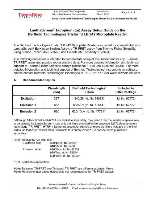
LanthaScreen® Europium (Eu) Assay Setup Guide on theBerthold Technologies Tristar² S LB 942 Microplate ReaderThe Berthold Technologies Tristar² LB 942 Microplate Reader was tested for compatibility with LanthaScreen® Eu Kinase Binding Assay, a TR-FRET assay from Thermo Fisher Scientific, using Kinase Tracer 236 (PV5592) and Eu-anti-GST Antibody (PV5594).The following document is intended to demonstrate setup of this instrument for any Eu-based TR-FRET assay and provide representative data. For more detailed information and technical support of Thermo Fisher Scientific assays please call 1-800-955-6288 ext. 40266. For more detailed information and technical support of Berthold Technologies’ instruments or software, please contact Berthold Technologies Bioanalytic at +49 7081-177-0 or .A. Recommended OpticsWavelength(nm) Berthold Technologies’FiltersIncluded inFilter PackageExcitation337 340/26 (Id. Nr. 54083) Id. Nr. 62772 Emission 1 665 665/7uv (Id. Nr. 525441) Id. Nr. 62772 Emission 2620 620/10uv (Id. Nr. 477311) Id. Nr. 627721Although filters 52544 and 47731 are available separately, they need to be mounted in a special way to be suitable for LanthaScreen®. Use only the filters provided in filter package 62772 (Measurement technology "TR-FRET / HTRF"). Do not disassemble, change or move the filters included in the filter slides, as that could render them unsuitable for LanthaScreen®. Do not use filters purchased separately.Filter Package 62772 includes:Excitation slide: 320/40, Id. Nr. 52733*340/26, Id. Nr. 54083Emission slide: 620/10uv, Id. Nr. 47731665/7uv, Id. Nr.52544520/10uv, Id. Nr. 38836** Not used in this application.Note: Eu-based TR-FRET and Tb-based TR-FRET use different excitation filters.Note: Monochromator based detection is not recommended for TR-FRET assays.IMPORTANT: The fluorescence module with extended spectral range is required to perform the LanthaScreen® Europium Assay in the Tristar² S.B. Instrument SetupThe following instructions are provided for the MikroWin software. The ICE software is also compatible with LanthaScreen®, and the same instrument settings can be easily programmed in ICE. Contact Berthold Technologies if you need support to program in ICE the instrument settings detailed here.1. Make sure the plate reader is turned on and then open the MikroWin software onthe computer.2. Click on Instrument >> Excitation Filter Slide. Check if the right filters areassigned to the right positions of the filter slides; if they are not, assign each filterto the corresponding position in the filter slide. Please follow the example below:Excitation slide xDSlot 1: 320/40 (HTRF Eu cryptate); usage: TRFluorescenceSlot 2: 340/26 (HTRF Tb cryptate); usage: TRFluorescence3. Click on Instrument >> Emission Filter Slide. Check if the right filters areassigned to the right positions of the filter slides; if they are not, assign each filter to the corresponding position in the filter slide (add new filters and enter thesettings below if needed). Please follow the example below:Emission Slide mDSlot 1: 620/10uv (HTRF Eu cryptate); usage: TRFluorescenceSlot 2: 665/7uv (HTRF XL665/APC); usage: TRFluorescenceSlot 3: 520/10uv; usage: TRFluorescence4. If you already have a pre-existing template for LanthaScreen®, open it and usethis document to review your settings; if you don’t have yet any suitable template, click on Settings in the menu bar at the top portion of the window to start creatinga new template.5. A new window will open. Select the Plate type corresponding to the plate you areusing and highlight the wells you most commonly will measure. If unsure aboutwhat plate type to select, contact Berthold Technologies for assistance.6. Click on the Measurement tab and look for the TRF operation.7. Double click on TRF to insert a TRF measurement operation. A new window willappear. If desired, enter a Name for the measurement operation. Configure the settings as shown in the screenshot below:•Enter Counting Time: 1.00•Select Aperture: 3 - Rd 2•Select Excitation Filter: 340/26 (HTRF Tb cryptate)*•Select Excitation Optic: 3 – Wide Filter 0.45mm•Select Emission Filter: 620/10uv (HTRF Eu cryptate)*•Enter Timing settings: Cycle Time 5000, Delay Time 100, Reading Time 300•Check Second Measurement•Select Excitation Filter: 340/26 HTRF Tb cryptate*•Select Emission Filter: 665/7uv (HTRF XL665/APC)*When finished, click OK.* The name of the filters in the software sometimes does not match the LanthaScreen® naming conventions, and sometimes filters named as “Tb cryptate” are mentioned in an Eu assay (or the other way around). This is not an error; filter naming was designed for HTRF® assays, but forLanthaScreen® different filter combinations are sometimes chosen for the best performance.8. To save the template, click on File in the main menu, then Template and Saveas. Browse to the desired folder, enter the desired filename and click OK.9. To start the measurement, enter the desired Plate ID to identify themeasurement. If you want to edit the wells to be measured, click on Settings and select the desired wells (see point 3). When you are ready, click Start. The plate tray will open; insert the plate and click OK to start the measurement.Test Your Plate Reader Set-up Before Using LanthaScreen® Eu Assays PurposeThis LanthaScreen® Eu Microplate Reader Test provides a method for verifying that a fluorescent plate reader is able to detect a change in time-resolved fluorescence energy transfer (TR-FRET) signal, confirming proper instrument set-up and a suitable response. The method is independent of any biological reaction or equilibrium and uses reagents that are on-hand for the LanthaScreen® assay.At a GlanceStep 1: This document can be found at /instrumentsetup.Step 2: Prepare individual dilutions of the TR-FRET acceptor (tracer, e.g. PV5592).2X = 1,600 nM, 800 nM, 400 nM, 200 nM and 50 nM.Note: To avoid propagating dilution errors, we do NOT recommend using serial dilutions. See page 10.Step 3: Prepare a dilution of the TR-FRET donor (Eu-Antibody, e.g. PV5594).2X = 125 nM Eu-chelate.Note: Concentration is based on the molarity of the Eu chelate (found on the Certificate of Analysis), NOT themolarity of the antibody, to account for normal variation in antibody labeling. See pages 11 - 12 forcalculations and method.Step 4: Prepare the plate and read.Step 5: Contact Technical Support with your results. E-mail us directly at ********************************** or in the US call 1-800-955-6288 ext. 40266. We will determine Z’-factors by comparing each concentration of acceptor to the200 nM acceptor data. Example results and data analysis are available on page 14.IntroductionThis LanthaScreen® Eu Microplate Reader Test uses diffusion-enhanced TR-FRET to generate a detectable TR-FRET signal. At high donor or acceptor concentrations, donor and acceptor diffuse to a suitable distance from one another to allow TR-FRET to occur, resulting in a signal. The response in diffusion-enhanced TR-FRET is easy to control because it is directly proportional to the concentrations of donor and acceptor in solution and is not related to a binding event.In this method, acceptor concentration varies while the donor concentration remains fixed. As the concentration of acceptor increases, the diffusion-enhanced TR-FRET signal increases. The signal from the acceptor concentrations are compared tothe signal from the lowest acceptor concentration to simulate assay windows from high to low allowing you to assess if your instrument is properly set-up and capable of detecting TR-FRET signals in the LanthaScreen® Assays.We designed the LanthaScreen® Eu technical note to use components and reagents that are generally used in the LanthaScreen® Eu Kinase Binding Assays. If you are using an Eu-based LanthaScreen® Activity or Adapta™ assay, call Technical Support for additional information.Materials RequiredComponent Storage Part Number Example ReagentsLanthaScreen® Eu-labeled antibody (donor) -20o C Various PV5594 LanthaScreen® Tracer (acceptor) -20o C Various PV55925X Kinase Buffer Room Temperature PV3189 PV3189*If you are using an Eu-based LanthaScreen® Activity or Adapta™ assay, call Technical Support for additional information.96-well polypropylene microplate or 1.5 mL microcentrifuge tubes384-well plate (typically a white, low-volume Corning 4513 or black, low-volume Corning 4514)Plate sealsSuitable single and multichannel pipettorsPlate reader capable of reading TR-FRETHandlingTo reread the plate on another day, seal and store the plate at room temperature for up to 5 days. To reread the plate, centrifuge the plate at 300 x g for 1 minute, remove seal and read.Important: Prior to use, centrifuge the antibody at approximately 10,000 x g for 5 minutes, and carefully pipette the volume needed for the assay from the supernatant. This centrifugation pellets aggregates present that can interfere with the signal. ProcedureStep 1: Set up your instrument using the information in this document.Step 2: Prepare the Acceptor (LanthaScreen® Kinase Tracer 236)Acceptor concentrations (2X) are individually prepared from a dilution of the Kinase Tracer stock (either 25 µM or 50 µM) to prevent propagation of error that can occur with serial dilutions. We suggest preparing 10 replicates for calculation of aZ’-factor. To accommodate replicates that use 10 µL per well, prepare 120 µL of each concentration. Prepare each concentration in micro-centrifuge tubes or a 96-well polypropylene plate and then transfer it to a 384-well plate.First prepare 1X Kinase Buffer A by adding 4 mL of 5X Kinase Buffer A to 16 mL of highly purified water. Diluted 1X Kinase Buffer A can be stored at room temperature.1.Prepare 2,500 nM acceptor stock solution:LanthaScreen® KinaseTracer Cat #Concentrationas SoldDilution to prepare a 2,500 nM solutionTracer 178 PV5593 25 µM Add 17 μL of tracer to 153 μL of 1X Kinase Buffer A Tracer 199 PV5830 25 µM Add 17 μL of tracer to 153 μL of 1X Kinase Buffer A Tracer 236 PV5592 50 µM Add 8.5 μL of tracer to 161.5 μL of 1X Kinase Buffer A Tracer 314PV6087 25 µM Add 17 μL of tracer to 153 μL of 1X Kinase Buffer A Tracer 1710PV6088 25 µM Add 17 μL of tracer to 153 μL of 1X Kinase Buffer A2. Prepare 120 μL of each 2X acceptor concentration from the 2,500 nM stock:96-well plate or tubes A1B1C1D1E1 2X Acceptor Concentration1,600 nM 800 nM 400 nM 200 nM 50 nM Final 1X Acceptor Concentration800 nM 400 nM 200 nM 100 nM 25 nM Volume 1X Kinase Buffer A43 μL 81.6 μL 100.8 μL 110.4 μL 117.6 μLVolume 2,500 nM Acceptor(prepared above)77 μL 38.4 μL 19.2 μL 9.6 μL 2.4 μLStep 3: Prepare the Donor (Eu-Chelate Labeled Antibody)Prepare a 2X stock of Eu-chelate at 125 nM that will result in a final assay concentration of 62.5 nM. This method relies on the concentration of Eu-chelate, NOT the concentration of antibody. The lot-to-lot variation in the number of Eu-chelates covalently bound to antibody can be accounted for by referring to the Eu-chelate-to-antibody ratio listed on the lot-specific Certificate of Analysis for your antibody. Multiply this ratio by the antibody concentration to calculate the Eu-chelate concentration.Example chelate concentrationsAntibody Concentration Antibody Molarity Chelate: Antibody Ratio Chelate Concentration0.5 mg/mL 3.3 μM 11 36.3 μM = 36,300 nM0.25 mg/mL 1.7 μM 8 13.6 μM = 13,600 nMExample Calculation: Prepare 1,000 μL of Eu-chelate:Eu-antibody = 0.5 mg/mL (3.3 μM) with a chelate:antibody ratio of 11Chelate: Stock = 3.3 μM x 11 = 36.3 μM = 36,300 nM.1X = 62.5 nM; 2X = 125 nMFormula V1 X C1 = V2X C2[Stock] [2X]Eu-Chelate V1 X 36,300 nM = 1,000 μL X 125 nM V1 = 3.4 μLAdd 3.4 μL of 36,300 nM stock to 996.6 μL 1X Kinase Buffer A.Step 4: Add Reagents to the 384-well plate and read1.DonorTransfer 10 μL of 2X Eu-chelate to rows A through J and columns 1 through 5 of the 384-well assay plate. Since you need only a single concentration, you can transfer this solution with a multichannel pipettor from a basin to all 50 wells. We recommend preparing the 1 mL solution in a 1.5 mL micro-centrifuge tube before transferring into the basin.2.AcceptorNote:To eliminate carryover, we recommend changing pipette tips for each concentration of acceptor.Note:After adding 2X acceptor, mix the reagents by pipetting up and down.Transfer 10 μL of the indicated concentration of 2X acceptor to the rows A-J of the corresponding column of the 384- well plate.2X Acceptor Column1,600 nM 1800 nM 2400 nM 3200 nM 450 nM 53. Read the plateThis step does not require any equilibration time.Step 5: Contact Technical SupportSend us your results by e-mailing us directly at ********************************** or in the US call 1-800-955-6288 ext.40266.We will help you evaluate your results by performing the following data analysis:Ratiometric data obtained on a Berthold Technologies Tristar² S LB 942 microplate reader.[Acceptor]800 nM 400 nM 200 nM 100 nM 25 nM Row A0.037 0.025 0.017 0.012 0.008 Row B0.036 0.026 0.018 0.012 0.008 Row C0.034 0.025 0.017 0.012 0.008 Row D0.033 0.024 0.017 0.012 0.008 Row E0.036 0.025 0.017 0.012 0.007 Row F0.036 0.023 0.017 0.012 0.008 Row G0.032 0.026 0.017 0.012 0.008 Row H0.033 0.021 0.016 0.012 0.008 Row I0.032 0.024 0.017 0.012 0.008 Row J0.032 0.023 0.018 0.012 0.008Data Analysis:[Acceptor]800 nM400 nM200 nM100 nM25 nM Average Ratio0.0340.0240.0170.0120.008 St dev0.00200.00130.00060.00020.0003 % CV 5.82 5.36 3.58 2.04 3.42 Assay4.31 3.05 2.15 1.52ReferenceWindowZ’-factor0.740.710.710.63For Research Use Only. Not intended for any animal or human therapeutic or diagnostic use.。
withanemphasison

MSU NSCL DAQ School—Notre Dame 2006
More to Read
• MSU NSCL DAQ:
– Everything: /daq/index.php
– Software project: /projects/nscldaq
– Tree parameter GUI for powerful manipulation of the definition of parameters, spectra, variables, and gates
– Xamine for easy display and operations of histograms – Tcl/Tk for user-tailorable control GUI and easy extension of
SpectroDaq Data Server
SpecTcl Xamine
Scalers
Scaler Configuration
offline analysis
MSU NSCL DAQ School—Notre Dame 2006
Disk
Hardware Setup
¾ Caen v785, 32-ch ADC ¾ Caen v775, 32-ch TDC ¾ Caen v830, 32-ch Scaler ¾ Trigger to be upgraded
• SpecTcl
– Home: /daq/spectcl/ – Project: /projects/nsclspectcl – Tree Parameters:
/daq/spectcl/treeparam/TreeParameter.html – Tcl/Tk: /
Samtec 微型抗摧断系统说明书

I N T E R C O N N E C T S O L U T I O N S G U I D ERugged contact systems, flexible power interconnects and rugged signal integrity create the foundation of Samtec’s micro rugged solutions for high cycle, high speed, high power and harshenvironment applications. Samtec’s rugged products are offered in conjunction with full engineering support, online tools and a service attitude that is unmatched in the connector industry.HIGH SPEEDS TO 56 Gbps PAM4EDGE RATE ®CONTACT DESIGN INCREASES WEAR LIFE EXPERTISE IN SIGNAL INTEGRITY DESIGN & ANALYSIS1,000+MATING CYCLES TIGER EYE ™ HEAT-TREATED BeCu CONTACTS MULTIPLE POINTS OF CONTACTFOR HIGH-RELIABILITY3 TO 60 AMPS CONFIGURABILITY OF POWER & SIGNAL SPACE-SAVING FORM FACTORRUGGED CONTACT SYSTEMFLEX POWERRUGGED SIGNAL INTEGRITY2RUGGED CONTACT SYSTEMSTiger Eye ™ contact system for high-reliability in rugged applications1,000+ mating cycles 0.80 mm to 2.00 mm pitchBoard-to-board, discrete wire and IDC cable assembliesRUGGED SIGNAL INTEGRITY SYSTEMSEdge Rate ® contact system for rugged signal integrity performance Performance to 56 Gbps PAM4 0.50 mm, 0.635 mm and 0.80 mm pitch Edge card and ultra-micro connectorsFLEXIBLE POWER SYSTEMSUltra-micro power to 17 A and incredible design flexibilityIndividually shrouded contactsSmall form factor, high power systems to 60 A Board-to-board and cable assembliesSEALED I/O SYSTEMSIP67 and IP68 rated for dust and water Variety of circular shell sizes with power, power/signal pinoutsRectangular designs for space savings Rugged latchingModified & Custom Solutions ...........................................................................................................................................Rugged Features .............................................................................................................................................................Power Integrity & Extended Life Product ™ .........................................................................................................................Severe Environment Testing ............................................................................................................................................Solutionator ®...................................................................................................................................................................Technology Centers .. (181920212223)4-78-1112-1516-17HIGH-RELIABILITY • MULTI-FINGER BeCu CONTACT • HIGH MATING CYCLESComponents (ISD2/CC81)& tooling available: /toolingEMI shielded 2.00 mmTiger Eye ™ discrete wire assembly(SS2SD/ST2M)2.00 mm PITCH TIGER EYE ™• Tiger Eye ™ is Samtec's most ruggedcontact system rated to 1,000+ mating cycles • Wide range of stack heights• Right-angle mating headers available • Optional screw downs, weld tabs and locking clips• Discrete wire assemblies available in 24-30 AWG PVC or Teflon ® wire 4/tigereyeOptional strain relief and variety of wiring optionsTCSD/EHTT2M/S2MTMM/SMMT2M/S2MMetal latching and screw down optionsS2SD/T2Mper pin3.8 ARight-angle availableVariety of stack heightsSurface mount or through-holeTFM/SFMSurface mount or through-hole tailsSFSST/TFMScrew down and retention latching options6-12 mm stack heightsHigh-density four row designMOLC/FOLC1.27 mm PITCH TIGER EYE ™• Screw down, locking clip, friction latching and weld tab ruggedizing options • Shrouded, polarized and keyed• Discrete wire assemblies available in single or double row, 28 and 30 AWG PVC or Teflon ® wire • Cable components (ISDF/CC03) and tooling availableLocking for increased unmating force (SFML/TFML)IDC cable assemblies withrugged strain relief (FFSD/FFMD, FFTP/FMTP)5Dupont ™ Teflon ® is a registered trademark of the E.I. du Pont de Nemours and Company or its affiliates./tigereyeTIGER EYE ™ CONTACT SYSTEM• Multi-finger design with several points of contact for high-reliability• Smooth, flat mating area increases mating cycles and lowers contact resistance • Heat-treated BeCu for the best combination of mechanical and electrical properties • Surface mount, micro slot tail increases solder surface area for higher joint strengthper pin3.2 ATEM/SEMVertical and right-angle mating headers0.80 mm PITCH TIGER EYE ™• Micro pitch and slim body for space-savings • 6 mm, 7 mm and 10 mm stack heights • Locking clip, alignment pins and weld tab ruggedizing features• Discrete wire assembly available with 32 AWG Teflon ® wire• Extended Life Product ™ testing availableRugged latching system for increased withdrawal forceSESDT/ TEM-L16HIGH-RELIABILITY • MULTI-FINGER BeCu CONTACT • HIGH MATING CYCLES/tigereyeComponents (ISDE/CC396) and tooling available: /toolingLocking for increased unmating force(SEML)TEMS/ SEMSCompatible with UMPT/UMPS for power/signal flexibilityper pin2.9 ATEM/ SEM1.00 mm PITCH CABLE SYSTEM• Crimp-style dual leaf contact system for reliable wire-to-board connection• 28 and 30 AWG cable options in PVC or Teflon®7/tigereye Components (ISS1, ISD1/CC09; T1SS, T1SD, T1PS, T1PD/T1M137-X) and tooling available: /tooling Dual leaf contact system for a reliable connectionT1PSTS1SDS1SS/ T1MT1SDS1SSTPanel-to-BoardCable-to-CableCable-to-BoardCustom solutions available (twisted pair cable shown):**************• Rugged positive latching for increased retention • Socket or terminal, single or double row assemblies • Vertical and right-angle mating headersOPTIMIZED FOR SI PERFORMANCE • INCREASED CONTACT WIPE • HIGH CYCLES 0.635 mm PITCH EDGE RATE®•Extremely slim 2.5 mm body width•Up to 120 positions in a 2-row design•5 mm stack height with others in development•Compatible with UMPT/UMPS for flexiblepower/signal solutions8ERX5ERX6ERX8 Sockets shown actual size at 40 total positions /edgerate0.50 mm PITCH EDGE RATE®•1.00 mm contact wipe for a reliable connection • Rugged friction locks and weld tabs available •Up to 40% PCB savings vs. ERM8/ERF8•Compatible with UMPT/UMPS for flexiblepower/signal solutionsStack Height Flexibility(Actual Size in mm)79101112ERM5/ERF5Right-angleavailable12 mmstack height7 mmstack heightERM6/ERF6Signal/power combinationwith UMPT/UMPSJ lead for easeof processingERM8/ERF87 mmstack heightRight-angle & edge mount available0.80 mm PITCH EDGE RATE ®• 1.50 mm extended wipe• Rugged metal latching for increased retention force • 360º shielding option reduces EMI • Compatible with UMPT/UMPS for flexible power/signal solutions• Cost-effective metal solder lock in development for a more secure connection to the boardStack Height Flexibility (Actual Size in mm)* In development 78*91011121314151618179Mating Cable Assemblies (ERCD/ERDP Series)360º shieldingSignal/power combination with UMPT/UMPS10 mmstack height with latching14 mmstack height with latching/edgerateEDGE RATE ® CONTACT SYSTEM• Smooth milled mating surface reduces wear and increases durability• Lower insertion and withdrawal forces • Robust when “zippered” during unmating• Minimized parallel surface area reduces broadside coupling and crosstalk • Designed, simulated and optimized for 50 Ω and 100 Ω systemsUP TO 56 Gbps PAM4 • CHOICE OF PITCH • EDGE RATE ® CONTACTS/edgecard0.80 mm & 1.00 mm PITCH SYSTEMS• High-speed Edge Rate ® contact system • Vertical, right-angle and edge mount • Power/signal combo to 60 A per power bank • Pass-through applicationHIGH-DENSITY EDGE CARD• Justification beam enables use of standard PCB tolerance • 0.50 mm ultra-fine pitch with up to 300 total I/Os • PCIe ® Gen 4 compatibleMICRO EDGE CARDS• 0.635 mm, 0.80 mm, 1.00 mm, 1.27 mm and 2.00 mm pitch • Optional rugged weld tabs, board locks and solder locks • Solutions for 1.60 mm (.062") and 2.36 mm (.093") thick cardsMisalignment mitigation(HSEC1-DV)56 Gbps with differentialpair (HSEC8-DP)PCI-SIG ® , PCI Express ® and the PCIe ® design marks are registered trademarks and/or service marks of PCI-SIG.HSEC8HSEC1-DVHSEC8-PV MEC5Beam ensures card and body are flushMEC1MEC6MECFHIGH-DENSITY • HIGH-RETENTION CONTACTS • SLIM ROW-TO-ROW DESIGNSLSSLSEMHERMAPHRODITIC RAZOR BEAM ™ INTERFACES• High-retention, high-speed Razor Beam ™ contacts • 0.50 mm, 0.635 mm and 0.80 mm pitch• EMI shielding available to limit signal degradation and optimize performanceRight-angle available formicro backplane applicationsFLOATING CONNECTORS• Provides 0.50 mm contact float in the X and Y axes to compensate for misalignment • 5 mm and 7 mm stack heights • Micro 0.50 mm pitchONE-PIECE INTERFACES• Robust design and mechanical hold-downs for high-shock and vibration applications • Optional rugged weld tabs and locking clips • 1.00 mm, 1.27 mm and 2.54 mm pitch designs5 - 12 mmstack height flexibilityLSHMFT5/FS5SEIFSISIBSIR1Profiles from1.65 mm to 10 mm11/micro17.1 A PER BLADE • MICRO 2.00 mm PITCH • DESIGN FLEXIBILITY MICRO 2.00 mm PITCH• Design flexibility as a power-only system or atwo-piece system for power/signal applications•Use with Samtec’s high-speed connector systemsfor a unique power/signal system (see chart)12SIGNAL CONNECTORMATED HEIGHT5 mm7 mm8 mm10 mmADM6/ADF6XBTE/BSE, BTH/BSH, BTS/BSS X XERM5/ERF5X XERM6/ERF6XERM8/ERF8X XLPAM/LPAF XQMS/QFS XQRM8/QRF8X XQTE/QSE, QTH/QSH,QTS/QSS X XSEAM/SEAF, SEAM8/SEAF8X XST4/SS4, ST5/SS5XTEM/SEM X XUMPT/UMPS/powerCREEPAGE CLEARANCEUMPT/UMPS 1.65 mm 2.20 mm•Tin or 10 µ" Gold plated power blades; 30 µ" Gold platingavailable to meet specific regulations•Selectively loading contacts achieves customer specificcreepage and clearance requirements; contact **************Choice of2, 3, 4 and 5position countsOptionalweld tabs5-10 mm stackheights available17.1 A/bladeUMPT/UMPS compared to othersmall form factor power solutions23 A/bladeper bladeTerminals shown actual size at 4 positions28.8 A/blade58.7 A/blade13P H A S E 15 Position,5 mm Stack HeightVertical UMPT & UMPS SeriesPOSITIONSSTACK HEIGHTS2, 3, 4, 55, 7, 8,10P H A S E 26 Position,9 mm Stack HeightVertical UMPT & UMPS SeriesPOSITIONSSTACK HEIGHTS6, 7, 8, 9, 106, 9, 11, 12, 14,16P H A S E 310 Position Right-AngleRight-Angle UMPT SeriesPOSITIONSOPTIONS2, 3, 4, 5, 6, 7, 8, 9, 10Latch for mating with cable assemblyP H A S E 44 Position Cable Assembly andUMPT Right-Angle with Staged BladesCable Assembly with LatchPOSITIONSMATES2, 3, 4, 5, 6, 7, 8, 9, 10UMPT Series vertical and right-angle with latch/powerLength, width and height shown actual sizeSamtec now offers power simulation that can calculate temperature increase in the connector area; contact *************************** for more details.SMALL FORM FACTORS • 10–60 A PER PIN/BLADE • INDIVIDUALLY SHROUDED CONTACTSMMSD/ IPL1MINI MATE ® & POWER MATE ®• Individually shrouded contacts for electrical and mechanical protection• .100" (2.54 mm) and .165" (4.19 mm) pitch • Discrete wire assemblies with 16-30 AWG PVC or Teflon ® cable• Selectively loading contacts achieves customer specific creepage and clearance requirements; contact **************14Metal or plasticrugged latching system/powerEXTREME POWER• AC or DC power, AC-DC combos and split power options (ET60T/ET60S)• High-density, double stacked power blades (LPHT/LPHS)• Selectively loading contacts achieves customer specific creepage and clearance requirements; contact **************3 or 5 signal rows in the same form factorLow 7.5 mm profile designCREEPAGECLEARANCE IPT1/IPS1MMSS(T)/MMSD(T) 2.55 mm 4.27 mm3.05 mm1.91 mm IPBT/IPBS PMSS(T)/PMSD(T)per pin10.3 ACREEPAGECLEARANCE LPHT/LPHS ET60T/ET60S5.63 mm 3.02 mm2.69 mm 1.87 mmET60T/ET60SLPHT/LPHSPMSDT/ IPBTIPT1/IPS1IPBT/IPBSRugged guide postsComponents and tooling availablePOWERSTRIP ™ SYSTEM• 23.5 A/blade to 58.7 A/blade (1 blade powered) • 5.00 mm and 6.35 mm pitch• Discrete wire assemblies with 10-16 AWG cable • Selectively loading contacts achieves customer specific creepage and clearance requirements; contact **************15MPT/MPSUPT/UPSMPTC/ MPSCPESS/PETMPSS/ MPTVertical and right-anglePower only or power/signal combinationsRugged latching system/power“Hinging” for 90º mating radius, ideal for blind mating (FMPT/FMPS)Discrete wire components (IMS5,IMSC5/CC46,CC81; IPS6/CC10) and tooling available: /toolingHermaphroditic power system with rugged screw downs (MPPT, UPPT)CREEPAGE CLEARANCE PET/PES/PETC/ PESC/PESS 3.66 mm 2.95 mm 5.80 mm2.71 mm 1.51 mm3.31 mm MPT/MPS/MPTC/ MPSC/MPSS/MPPT UPT/UPS/UPPTDual blade contactsCCP/CCRFLEXIBLE SEALED CIRCULAR SYSTEMS• Metal or plastic, 12 mm, 16 mm and 22 mm shells • Flexible pin configuration, gender and panel interface termination• Bayonet-style latching systems meet IP68 requirements • Cost-effective crimp version available• Mini push-pull latching system meets IP67 requirements for dust and waterproof sealing16Crimp 12 mm shellIP67 & IP68 • BAYONET/PUSH-PULL CIRCULARS • SPACE-SAVING RECTANGULARSKitted components for efficient field assembly/sealedMCP/MCRACP/ACRACP/ACRMini push-pull system16 mm size metal shell22 mm size plastic shell17SCPU25-45% panel area savings/sealedSEALED RECTANGULARS• Space saving design • Meets IP68 requirements • USB and Ethernet signal systems • Rugged dust caps available• 1 or 2-port vertical and right-angle panel mount socketsTHREADED CIRCULARS• Meets IP68 requirements for dust and waterproof sealing • Rugged overmold design• USB, Mini USB and Ethernet signal systems • 10 and 17 shell sizes• Rugged dust caps and panel-to-board termination availableRCERCUAudibleclick positive latching for quick connect/disconnectVertical or right-angleRPCURPBURPBEUSB type A and B10 or 17 shell sizeEthernet meets CAT3, CAT5 and CAT5eSCRESSCPESCRUSWILLINGNESS, SUPPORT & EXPERTISE18ExpressModificationsEngineeredCustoms23%5%Customs and Modifications make up about 28% of Samtec’s total sales92% do not require engineering or tooling chargesA substantial percentage of eachMicro Rugged product segment is customTiger Eye ™Edge Rate ®Edge Card PowerSealed I/O19%9%44%30%8%INDUSTRY LEADING CUSTOMER SERVICE FLEXIBLE IN-HOUSE MANUFACTURING SIGNAL INTEGRITYEXPERTISEEngineered CustomMulti-power staging, power/signal combo, header/socket combo, custom bodyExpress ModificationStandard PowerStrip ™ cable with non-standard end 2 optionFLEXIBLE SOLUTIONS• Full engineering, design and prototype support • Design, simulation and processing assistance • Quotes and samples turned around in 24 hours • Flexible, quick-turn manufacturing • Dedicated Application Specific Product engineers and technicians• Modified or custom options for board level connectors and cable assemblies including: contacts, bodies, stamping, plating, wiring, molding, ruggedizing features and much moreContact the Application Specific Products Group at ************** for express modifications or engineered customs.19OPTIONS FOR HIGH-RELIABILITY, HIGH-RETENTION AND HIGH-CYCLE LIFERUGGEDIZING OPTIONSWELD TABSSignificantly increase sheer resistance of connectorto PCBSHIELDING360° shielding reduces EMIGUIDE POSTSEasy and secure matingBOARD STANDOFFSPrecision machined standoffs for 5 mm to 25 mm board spacingSCREW DOWNS Secure mechanical attachment to the boardBOARD LOCKSBoards are mechanicallylocked togetherRETENTION PINSIncrease unmating forceby up to 50%FRICTION LOCKSMetal or plastic friction locks increase retention/withdrawal forcePOSITIVE LATCHINGManually activated latches increase unmating forceby up to 200%JACK SCREWS Ideal for high normal force, zippering and other ruggedapplicationsEDGE RATE ®Designed for Signal Integrity Superior Impedance Control Reduced Broadside CouplingTIGER BEAM ™Best CostReliable Performance Post & Beam ContactBLADE & BEAMMating/Alignment “Friendly”Cost-effectiveTIGER CLAW ™Dual Wipe Contact Pass-through ApplicationsUltra-low ProfileTIGER EYE ™High-reliability High Mating Cycles Multi-finger ContactCONTACT SYSTEMS20POWER INTEGRITY SERVICES• • • • • /powerintegrity EXTENDED LIFE PRODUCT ™• • • • /ELP**************POWER INTEGRITYCERTIFIEDCREEPAGECLEARANCEPITCHTYPECONTACTSERIES*0.50 mm Q Series ® Strip Blade & Beam QSH/QTH Basic Strip Blade & Beam BSH/BTH 0.635 mmQ Series ® Strip Blade & Beam QSS/QTS Basic Strip Blade & Beam BSS/BTS 0.80 mmEdge Rate ® Strip Edge Rate ®ERF8/ERM8Edge CardEdge Rate ®HSEC8Q Rate ®StripEdge Rate®QRM8/QRF8Q Series ® Strip Blade & Beam QSE/QTE Basic Strip Blade & Beam BSE/BTE StripTiger Eye ™SEM/TEM 1.00 mm StripTiger Claw ™CLM/FTMH 1.27 mmSEARAY ™ArrayEdge Rate®SEAF/SEAM Strip Tiger Eye ™SFM/TFM Strip Tiger Claw ™CLP/FTSH Strip Tiger Beam™FLE/FTSH 2.00 mm Strip Tiger Eye ™SMM/TMM Strip Tiger Claw ™CLT/TMMH 2.54 mmStrip Tiger Claw™SSM/TSM StripTiger Claw ™BCS/TSW* Tested socket/terminal combination shown. Other mating headers also available. Contact Samtec if header design you need is not shown.10 YEAR MFGEXTENDED LIFEPRODUCTHIGH MATINGCYCLES21Severe Environment Testing is a new Samtec initiative to test our products beyond typical industry standards and specifications, many set forth by common requirements for rugged industries. Several of our products will undergo additional testing to ensure they are more than suitable for industrial, military, automotive and other extreme applications.PRODUCTS TO BE TESTED:• Rugged Tiger Eye ™ connectors• Hermaphroditic Razor Beam ™ connectors• SEARAY ™ high-density arrays• Edge Rate ® rugged signal integrity connectors• AcceleRate ® HD ultra-micro connectors• Ultra Micro Power systems• High-speed coax and twinax cable assembliesPlease contact ************** for more information and test results when available.TESTING WILL INCLUDE:• Higher mating cycle testing• Intense shock and vibration• Altitude testing• ESD testing• Temperature cycling• And morePRND NETWORK vs. MIL-PRF-83401 PERFORMANCE TEST OR CONDITION MIL-PRF-83401VISHAY FOIL RESISTORS C Typical Resistance Temp Characteristic ppm/ºC ± 50± 2Tracking to Reference Element (-55 to +125 ºC)ppm/ºC ± 5± 2Max Ambient Temp at Rated Wattage ± 70 ºC Max Ambient Temp at Zero Power ± 125 ºC Thermal Shock and Power Conditioning ± 0.25 % ± 0.03 %± 0.015 % ± 0.015 %Low Temperature Operation ∆R ∆Ratio ± 0.10 % ± 0.02 %± 0.01 % ± 0.01 %Short Time Overload ∆R ∆Ratio ± 0.10 % ± 0.02 %± 0.01 % ± 0.01 %Terminal Strength ∆R ∆Ratio ± 0.10 % ± 0.03 %± 0.01 % ± 0.01 %Resistance to Soldering Heat ∆R ∆Ratio ± 0.10 % ± 0.02 %± 0.01 % ± 0.01 %Moisture Resistance ∆R ∆Ratio ± 0.20 % ± 0.02 %± 0.01 % ± 0.01 %Shock (Specified Pulse)∆R ∆Ratio ± 0.25 % ± 0.03 %± 0.01 % ± 0.01 %Vibration, High Frequency ∆R ∆Ratio ± 0.25 % ± 0.03 %± 0.01 % ± 0.01 %Load Life (Per EEE-INST-002) (+70 ºC, Full Power, 2000 hours)∆R ∆Ratio ± 0.10 % ± 0.03 %± 0.05 % ± 0.02 %+25 ºC Power Rating (1000 hours)∆R ∆Ratio ± 0.10 % ± 0.03 %± 0.01 % ± 0.01 %High Temperature Exposure (+125 ºC, 100 hours)∆R ∆Ratio ± 0.10 % ± 0.03 %± 0.01 % ± 0.01 %Low Temperature Storage ∆R ∆Ratio ± 0.10 % ± 0.02 %± 0.01 % ± 0.01 %Insulation Resistance 10,000 MΩResistance Tolerance and, when applicable, Resistance Ratio Accuracy ± 0.1 % (B)± 0.5 % (D) ± 1.0 % (F)± 0.1 % (B)± 0.5 % (D)22•Wide variety of search parameters and filters: creepage and clearance (power), pitch, stack height, etc. •Easily sort results to find the right mated set•Live chat with engineers for custom options•Immediately download models and open Specs KitQUICKLY BUILD MATED SETS ONLINETo build your mated set, visit /solutionatorSAMTEC TECHNOLOGY CENTERS ENABLE COMPLETE SYSTEM OPTIMIZATION FROM SILICON-TO-SILICON™HIGH–SPEEDCABLE MICROELECTRONICSADVANCEDINTERCONNECTSOPTICSSYSTEM SIGNALINTEGRITYPRECISION RFSamtec's Technology Centers offer high-level design and development of advanced interconnect systems and technologies, along with industry-leading signal integrity expertise which allows us to provide effective strategies and technical support for optimizing the entire serial channel of high-performance systems. Because Samtec's Technology Centers are not limited by the boundaries of traditional business units,we are able to work in a fully integrated capacity that enables true collaboration and innovation to support the demands of today, and the challenges of tomorrow.In-house R&D manufacturingof precision extruded cableand assembliesAdvanced IC packaging design, support and manufacturing capabilities R&D, design, developmentand support of micro opticalengines and assembliesRF interconnect design anddevelopment expertise, withtesting to 65 GHzHigh precision stamping,plating, molding andautomated assemblyFull channel signal and powerintegrity analysis, testing andvalidation services /tech-centers23UNITED STATES • NORTHERN CALIFORNIA • SOUTHERN CALIFORNIA • SOUTH AMERICA • UNITED KINGDOM GERMANY • FRANCE • ITALY • NORDIC/BALTIC • BENELUX • ISRAEL • INDIA • AUSTRALIA / NEW ZEALAND SINGAPORE • JAPAN • CHINA • TAIWAN • HONG KONG • KOREANOVEMBER 2018。
- 1、下载文档前请自行甄别文档内容的完整性,平台不提供额外的编辑、内容补充、找答案等附加服务。
- 2、"仅部分预览"的文档,不可在线预览部分如存在完整性等问题,可反馈申请退款(可完整预览的文档不适用该条件!)。
- 3、如文档侵犯您的权益,请联系客服反馈,我们会尽快为您处理(人工客服工作时间:9:00-18:30)。
2NEUKD-Literatur.Permanenter Allradantrieb hat bei Volkswagenund Audi schon eine fast 15jährige Geschichte.Bei Volkswagen lenkte unter anderem eineViscokupplung das Antriebsmoment auf dieHinterachse und bei Audi ein Torsendifferential.Das schlupferkennende System wird aufgrundeiner Drehzahldifferenz zwischen der Vorder-achse und der Hinterachse aktiviert und verteiltdann die Antriebsmomente entsprechend auf diebeiden Achsen.Die bisher bei Volkswagen verwendete Visco-Kupplung konnte allein den Schlupf, aber nichtdessen Ursache erkennen.Mit der Entwicklung der Haldex-Kupplung ist einriesiger Schritt moderner Allradtechnik gelungen.Die Haldex-Kupplung ist regelbar. Über einenRechner werden zusätzliche Informationen beider Regelarbeit berücksichtigt. Nicht mehr derSchlupf alleine ist entscheidend für die Verteilungder Antriebskräfte, sondern ebenso der fahr-dynamische Zustand des Autos. Der Rechnergreift über CAN-Bus auf die ABS-Raddrehzahl-sensoren und die Motorsteuerung (Signal desFahrpedals) zurück.Mit diesen Daten besitzt der Rechner allewesentlichen Informationen über Geschwindig-keit, Kurvenfahrt, Schub- oder Zugbetrieb, under kann optimal auf die Situationen reagieren. SSP 206/001Vorteile der Haldex-Kupplung·permanenter Allradantrieb mit elektronischgeregelter Lamellenkupplung·Frontantriebs-Charakteristik·schnelles Ansprechverhalten·kein Verspannen beim Parken und Rangieren·unkritisch gegenüber unterschiedlichen Reifen(z.B. Notrad)·keine Einschränkungen beim Abschleppen mitangehobener Achse·voll kombinierbar mit Schlupfregelsystemenwie ABS, EDS, ASR, EBV und ESP3Auf einen BlickAllradantrieb. . . . . . . . . . . . . . . . . . . . . . . . . . . . . . . . . .4Haldex-Kupplung . . . . . . . . . . . . . . . . . . . . . . . . . . . . . .8Mechanik . . . . . . . . . . . . . . . . . . . . . . . . . . . . . . . . . . .10Hydraulik. . . . . . . . . . . . . . . . . . . . . . . . . . . . . . . . . . . .14Prüfen Sie Ihr Wissen . . . . . . . . . . . . . . . . . . . . . . . . . .19Systemübersicht. . . . . . . . . . . . . . . . . . . . . . . . . . . . . . .20Elektrik. . . . . . . . . . . . . . . . . . . . . . . . . . . . . . . . . . . . . .22Fahrsituationen . . . . . . . . . . . . . . . . . . . . . . . . . . . . . . .34Funktionsplan . . . . . . . . . . . . . . . . . . . . . . . . . . . . . . . .36Eigendiagnose. . . . . . . . . . . . . . . . . . . . . . . . . . . . . . . .38Prüfen Sie Ihr Wissen . . . . . . . . . . . . . . . . . . . . . . . . . .404Der Allrad-AntriebsstrangDer Allrad-Antriebsstrang wurde mit der neuenLamellenkupplung für A-Plattform-Fahrzeugedes Konzerns mit quer eingebautem Front-triebwerk entwickelt.Die neue Kupplung ist eine kompakte Bau-gruppe, die an gleicher Stelle plaziert ist wie dieVisco-Kupplung des bisherigen Antriebs.Sie sitzt am Hinterachsgetriebe und wird von derKardanwelle angetrieben.AllradantriebSSP 206/003Das Motordrehmoment wird über das Schalt-getriebe, das Vorderachsdifferential und denVorderachsantrieb auf die Kardanwelle über-tragen.Die Kardanwelle ist mit der Eingangswelle derHaldex-Kupplung verbunden.In der Haldex-Kupplung ist die Eingangswellevon der Ausgangswelle zum Hinterachs-differential getrennt.Eine Drehmomentübertragung auf das Hinter-achsdifferential kann nur über das geschlosseneLamellenpaket der Haldex-Kupplung erfolgen.SSP 206/0025Änderung an der Kraftstoff-versorgungSchalttafeleinsatzes.SSP 206/007Ausgleichsbehälter78Die Haldex-LamellenkupplungDie Haldex-Lamellenkupplung funktioniert auf der Basis von drei Hauptelementen der Mechanik der Hydraulik und der ElektronikHaldex-Kupplung SSP 206/008Mechanik Hydraulik Elektronik9SSP 206/009Die Mechanik besteht im Wesentlichen aus dendrehenden und sich bewegenden Teilen. Dazugehören-die Eingangswelle -die Innen- und Außenlamellen -die Hubscheibe -die Rollenlager mit den Ringkolben -die AusgangswelleDie Elektronik besteht im Wesentlichen aus -der elektrischen Ölpumpe -dem Stellmotor für das Regelventil -dem Temperatur-Geber -dem SteuergerätDie Hydraulik besteht im Wesentlichen aus-den Druckventilen -dem Akkumulator -dem Ölfilter -den Ringkolben -dem Regelventil DruckbegrenzungsventilAkkumulatorAusgangÖlfilterSteuergerätEingangLamellen-Kupplung StellmotorRegelventil Temperatur-GeberElektrischeÖlpumpeRingkolbenHubscheibe10Die Lamellen-KupplungDie Eingangswelle der Kupplung, in der Ab-bildung blau dargestellt, ist mit der Kardanwelleverbunden. Mit dem Drehen der Eingangswellewerden die Rollenlager für den Hubkolben undfür den Arbeitskolben sowie die Außenlamellenmitgenommen.Hub- und Arbeitskolben sind Ring-kolben Die Ausgangswelle, in der Abbildung rotdargestellt, bildet von der Hubscheibe bis zumTrieblingskopf eine Einheit. Auch die Innen-lamellen sind über eine Längsverzahnung mitder Ausgangswelle verbunden. MechanikSSP 206/010Außenlamelle Rollenlager für ArbeitskolbenArbeitskolbenAusgangswelleTrieblingskopfHubscheibeInnenlamelleEingangswelleRollenlager für HubkolbenHubkolben11Dieser Öldruck wird über einen Ölkanal an den Arbeitskolben gelenkt. Der Arbeitskolben wird durch den Öldruck nach links gegen die Lager-rolle und Druckplatte des Lamellenpaketes gedrückt.Das Lamellenpaket wird zusammengepreßt.Die Verbindung der Eingangswelle zur Aus-gangswelle der Kupplung ist hergestellt, und damit der Allradantrieb.FunktionIm Moment des Beschleunigens dreht die Ein-gangswelle mit dem Rollenlager des Hubkolbens um die noch stehende Hubscheibe der Aus-gangswelle. Dabei läuft das Rollenlager des Hubkolbens über eine Berg- und Talbahn der Hubscheibe. Diese Auf- und Abbewegungen gibt die Rolle weiter auf den Hubkolben. Der Hub-kolben wird dadurch in Hubbewegung versetzt und baut einen Öldruck auf.SSP 206/011LamellenpaketEingangswelleÖlkanalDruckplatteAusgangswelleHubscheibe12MechanikDie Ausgangswelle mit der Längsverzahnung für die Innenlamellen bildet mit der Hubscheibe und dem Trieblingskopf eine Einheit.Die Rollenlager sind in dieser Ab-bildung nur zur Orientierung dar-gestellt.SSP 206/011Bei Drehzahldifferenz zwischen der Vorder- und der Hinterachse dreht das Außenlamellen-gehäuse mit den Rollenlagern um die Ausgangs-welle, so daß die Rollenlager des Hubkolbens auf der Hubscheibe abrollen. Durch die Form der Hubscheibe durchlaufen die Rollenlager des Hubkolbens eine Berg- und Talbahn und geben diese Hubbewegung auf den im Gehäuse lie-genden Hubkolben weiter.Aus Übersichtlichkeitsgründen haben wir die Hubscheibe mit zwei Nocken dargestellt. In Wirklichkeit befinden sich jedoch drei Nocken auf derHubscheibe. Die Funktion bleibterhalten.Rollenlager für ArbeitskolbenTrieblingskopf HubscheibeInnenlamelleRollenlager für Hubkolben13Durch die Hubbewegung des Hubkolbens wird ein Öldruck erzeugt, der sich über den Ölkanal auf den Arbeitskolben auswirkt und diesen nach links treibt.Über die Rollenlager des Arbeitskolbens wird der Druck über eine Druckplatte auf das Lamellen-paket übertragen. Die Kupplung schließt und stellt so eine Verbindung zwischen der Vorder- und der Hinterachse her.Die Rollenlager sind in dieser Abbil-dung nur zur Orientierung darge-stellt.SSP 206/012Das Außenlamellengehäuse mit der Längsver-zahnung für die Außenlamellen und den Rollen-lagern bilden eine Einheit mit der Eingangswelle.Die Rollenlager befinden sich, wie hier dargestell, im Außenlamellenge-häuse.AußenlamellengehäuseEingangswelleHubkolbenLängsverzahnungÖlkanalKupplungsgehäuse1415Druckaufbau der elektrischen Ölpumpe (Vordruck)Eine elektrische Ölpumpe wird ab einer Motor-drehzahl > 400/min elektrisch angesteuert.Über ein Sieb zieht die elektrische Öldruck-pumpe Hydrauliköl aus dem drucklosen Raum des Kupplungsgehäuses und pumpt das Öl durch einen Filter über die Saugventile an die Hubkolben.Dadurch werden die Hubkolben mit Öl versorgt und gleichzeitig über die Rollenlager an der Hubscheibe zur Anlage gebracht und gehalten.Gleichzeitig gelangt das Öl über das Regelventil und durch die Druckventile an den Arbeits-kolben, der ebenfalls zur Anlage gebracht wird. Durch diesen Vordruck wird außerdem das Spiel aus dem Lamellenpaket genommen, so daß ein schnelles Ansprechverhalten der Kupplung erreicht wird.Der Vordruck von 4 bar wird von dem Akku-mulator bestimmt. Eine weitere Aufgabe des Akkumulators ist es, die Druckschwankungen zuglätten.161718Der Druckaufbau über Hubkolben(Regelventil geöffnet)Das Regelventil ist geöffnet, so kann das Öl durch das Regelventil über den Akkumulator in den Ölsumpf zurückfließen.Dadurch findet kein Druckaufbau am Arbeits-kolben statt. Die Lamellenkupplung ist geöffnet, und es findet keine Drehmomentübertragung statt.Der Akkumulator hält in der Rücklaufleitung des Regelventils den Vordruck aufrecht.In der Rücklaufleitung des Regelventils zum Akkumulator herrscht Vordruck(4 bar).HydraulikSSP 206/01719Prüfen Sie Ihr Wissen1.Was zeichnet die Haldex-Kupplung besonders aus?Permanenter Allradantrieb mit elektronisch geregelter Lamellenkupplung Spurstabiles Beschleunigen (Frontantriebscharakteristik)Verzögertes Ansprechverhalten Schnelles AnsprechverhaltenUnkritisch gegenüber unterschiedlichen Reifengrößen (z. B. Notrad)Verwendung von CAN - SignalenKeine Einschränkungen beim Abschleppen mit angehobener Achse2.Die Haldex-Kupplung funktioniert auf der Basis von drei Hauptelementen. Welche sind das?Elektronik Pneumatik Hydraulik Mechanik3.Welche Bauteile sind mit den drei Hauptbauteilen der Kupplung verbunden?Ausgangswelle: ......................................, ....................................., ......................................, .....................................Eingangswelle: ........................................., ........................................., .........................................Kupplungsgehäuse: ........................................., ........................................., .........................................4.Die elektrische Ölpumpe wird elektrisch angesteuert, wenn die Motordrehzahl größer ist als 400 Umdrehungen pro Minute.kleiner ist als 400 Umdrehungen pro Minute.20SystemübersichtHandbremsschalter F9SSP 206/018Stellmotor V184SteckanschlußElektrikDas Motor-SteuergerätDas Motor-Steuergerät wird bei den ver-schiedenen Motoren auch unterschiedlich ver-baut, überwiegend jedoch im Wasserkastenuntergebracht.Das Motorsteuergerät arbeitet drehmoment-orientiert. Dies wurde durch die neue E-Gas-Funktion möglich.SSP 206/023Signalverwendung für die AllradelektronikDas Motorsteuergerät stellt folgende Signaleüber CAN-Bus zur Verfügung.-Motordrehzahl-Gaspedalstellung-MotormomentAuswirkung bei Signalausfall-kein MotorlaufGeber für Motordrehzahl G28Der Geber für Motordrehzahl ist ein Induktiv-geber, der auf der linken Seite des Motors in der Nähe des Ölfilters eingebaut ist.Elektrische SchaltungJ...SignalverwendungDer Geber erfaßt die winkelgenaue Stellung der Kurbelwelle zur Festlegung des Zünd- und Ein-spritzzeitpunktes sowie der Motordrehzahl.MotordrehzahlSobald der Motor dreht, bewegt sich das Geber-rad am G28 vorbei, und es entsteht eineWechselspannung, deren Frequenz sich mit der Motordrehzahl ändert.Die Frequenz der Wechselspannung dient dem Steuergerät zur Erkennung der Motordrehzahl.ZündzeitpunktZur Erkennung der Kurbelwellenstellung hat das Geberrad eine Zahnlücke von 2 Zähnen, die als Bezugsmarke dient.Auswirkungen bei SignalausfallBei Ausfall des Drehzahl-Signals vom Geber für Motordrehzahl ist kein Motorstart bzw. Motorlauf möglich.SSP 206/019SSP 206/020G28Das SteuergerätDas Steuergerät überwacht die Funktion und Plausibilität der beiden Geber G79 und G185, deren Kennlinienverlauf unterschiedlich ist(siehe Diagramm). Fällt ein Geber aus, dient der andere als Ersatz, und die Fehlerlampe K132 für elektrische Gasbetätigung im Kombi-Instument leuchtet auf.SSP 206/021U GaspedalwegW i d e r s t a n dSSP 206/022Geber für Gaspedalstellung G79/G185Der Geber für Gaspedalstellung G79/G185 dient zur Übermittlung des Fahrerwunsches an das Motorsteuergerät.Der Pedalwertgeber gibt ein der Gaspedal-stellung entsprechendes Analogsignal an die Motronic. Zur Sicherung der E-Gas-Funktion besitzt der Pedalwertgeber zwei voneinander unabhängig arbeitende Potentiometer G79 und G185.E-Gas: Elektrisch betätigte Drossel-klappeDer mechanische Gaszug wird durch eine elektronische Steuerung ersetzt.Nähere Informationen finden Sie imSelbststudienprogramm Nr. 210.ElektrikSSP 206/031Beim Einschalten der Zündung erfolgt ein Selbst-test des Steuergerätes. Das Steuergerät besteht aus zwei Rechnersystemen für eine hohe Fehler-sicherheit. Neben der Überwachung einzelner Komponenten überwachen sich die zwei Rechnersysteme auch gegenseitig.Signalverwendung für Allradelektronik Über CAN-Bus werden folgende Signale dem Haldex-Steuergerät zur Verfügung gestellt:-Geber für Raddrehzahl -Bremslichtschalter -Handbremsschalter-Geber für LängsbeschleunigungIst das Fahrzeug auch mit ESP ausgestattet, über-wiegt eine notwendige ESP-Regelung vor einer Allradfunktion.Das Steuergerät für ABS J104Das Steuergerät von der Fa. ITT-Automotiv ist mit der Hydraulikeinheit zu einer Baugruppe zusam-mengefaßt und sitzt im Motorraum links.Auswirkung bei SignalausfallBei einem unwahrscheinlichen Gesamtausfall der Steuergeräte steht dem Fahrer nur noch das normale Bremssystem ohne Regelung und keine Allrad-Regelung zur Verfügung.SSP 206/024Geber für Raddrehzahl G44-G47Der Geber für Raddrehzahl erfaßt die Drehzahl-änderung des Rades und gibt sie als Drehzahl-information an das Steuergerät.ElektrikDer Geber für Raddrehzahl ist in der Nähe des Achsflansches angebracht. Auf dem Achsflansch ist ein Impulsrad so positioniert, daß es sich bei Drehbewegung des Rades am Kopf des Dreh-zahlgebers vorbeibewegt. Zwischen Zahn und Zahnlücke des Impulsrades werden magnetische Feldlinien verzerrt. Dadurch wird in der Spule des Drehzahlgebers eine sinusförmige Wechsel-spannung induziert, deren Frequenz von der Raddrehzahl abhängig ist.Das Steuergerät erkennt aus den Frequenzen die aktuelle Raddrehzahl einzelner Räder.Auswirkungen bei Signalausfall -keine ABS-Regelung-keine Regelung des Allrad-AntriebsDer Ausfall eines Radsensors bewirkt noch keine Einschränkung des Allrad-Antriebs.Der Geber für Längsbeschleunigung G249Der Geber für Längsbeschleunigung G249 ist an der A-Säule rechts angebracht.Bei geschlossener Haldex-Kupplung sind die Vorder- und Hinterräder starr gekoppelt.Die Berechnung der wahren Fahrzeug-Geschwindigkeit wird aus den einzelnen Rad-Drehzahl-Gebern ermittelt und kann beiniedrigen Reibwerten und geschlossener Haldex-Kupplung unter bestimmten Bedingungen zu ungenau sein.Die gemessene Längsbeschleunigung dient der Absicherung der theoretisch ermittelten Fahr-zeuggeschwindigkeit.Auswirkung bei SignalausfallOhne die zusätzliche Messung der Längs-beschleunigung kann unter ungünstigenBedingungen die wahre Fahrzeuggeschwindig-keit nicht genau ermittelt werden. Die ESP- und ASR-Funktion fallen aus.Setzt ESP-Regelung ein, wird die Haldex-Kupplung geöffnet.Elektrische SchaltungDer Geber für Längsbeschleunigung ist über drei Leitungen mit dem Steuergerät J104 verbunden.Aufbau und Funktion entnehmen Sie bitte dem Selbststudienprogramm204.SSP 206/025SSP 206/026Auswirkungen bei SiganlausfallEs werden ersatzweise die CAN-Bus-Informatio-nen verwendet.SignalverwendungDer Bremslichtschalter gibt die Information …Bremse betätigt“ an das ABS-Steuergerät I104.Das Steuergerät informiert über CAN-Bus das Haldex-Steuergerät, worauf beim Bremsen das Haldex-Steuergerät sofort über den Stellmotor den Druckregler öffnet und die Haldex-Kupplung drucklos wird.Elektrische SchaltungSSP 206/027SSP 206/028Der Bremslichtschalter FDer Bremslichtschalter F befindet sich am oberen Ende des Bremspedals und ist an der Pedalstütze befestigt.ElektrikDer Handbremsschalter F9Der Handbremsschalter F9 ist unterhalb des Handbremshebels angebracht.SignalverwendungDer Handbremsschalter gibt die Information …Handbremse betätigt“ an das ABS-Steuergerät J104 und gleichzeitig an das Haldex-Steuergerät J492. Während das ABS-Steuergerät die Information …gefiltert“ über CAN-Bus an das Haldex-Steuergerät weitergibt, erhält dasHaldex-Steuergerät die Information direkt vom Handbremsschalter.Wird das Signal des Handbremsschalters F9 erkannt, wird die Haldexkupplung geöffnet.Elektrische SchaltungAuswirkungen bei Signalausfall-keine Regelung des Allrad-Antriebs sowie Komforteinbußen bei der ABS-RegelungSSP 206/029ElektrikDer Temperatur-Geber der Haldex-Kupplung G271Der Temperatur-Geber der Haldex-Kupplung ist in der Nähe des Regelventils im Gehäuse des Haldex-Steuergerätes eingebaut und wird vom Hydrauliköl umspült.SignalverwendungDer Temperatur-Geber fühlt die aktuelleHydrauliköltemperatur und gibt die Information an das Haldex-Steuergerät.Diese Information dient der Anpassung an die sich ändernde Viskosität des Hydrauliköls.Übersteigt die Hydrauliköl-Temperatur 100°C, wird die Kupplung drucklos geschaltet. Sinkt die Temperatur wieder unter 100°C, wird wieder Druck auf die Kupplung gegeben.Auswirkungen bei Signalausfall -Abschaltung des AllradantriebsTemperatur Hydrauliköl/Viskosität Regelventilim Minusbereich zähflüssig etwas weiter geöffnet normal 20°C normal normal geöffnet über 20°Cdünnflüssigetwas weniger geöffnetSSP 206/032Temperatur-GeberSSP 206/033Das Haldex-Steuergerät J492Das Haldex-Steuergerät ist direkt am Gehäuse der Haldex-Kupplung befestigt und bildet zusammen mit dem Stellmotor und dem Regel-ventil eine Einheit.Aufbau und FunktionDas Steuergerät der Haldex-Kupplung ist über CAN-Bus mit dem Motor- und dem ABS-Steuer-gerät verbunden. Aus den Sensor-Signalen der Steuergeräte entscheidet das Haldex-Steuer-gerät, mit welchem Öldruck die Lamellen der Haldex-Kupplung beaufschlagt werden.Der Öldruck an den Lamellen der Haldex-Kupplung bestimmt, welches Drehmoment auf die Hinterachse übertragen werden soll.Auswirkung bei Signalausfall -kein AllradantriebBei Fahrzeugen mit Automatik-getriebe findet ein Signal-Austausch über CAN-Bus zwischen dem Motor-steuergerät und dem Steuergerät fürAutomatikgetriebe statt.ElektrikDer Stellmotor V184Der Stellmotor ist im Gehäuse des Haldex-Steuergerätes integriert.Aufbau und FunktionDer Stellmotor wird vom Haldex-Steuergerät mit Spannung versorgt und fungiert als Schrittmotor.Über ein kleines Ritzel verändert der Stellmotor auf Befehl des Haldex-Steuergerätes die Höhe des Regelstiftes im Druckregler.Die Höhe des Regelstiftes verändert im Druck-regler den Querschnitt einer Rücklaufbohrung. So wird der Druck am Arbeitskolben der Lamellen bestimmt.SSP 206/034Regler geschlossen:Regler teilweise geöffnet:Regler ganz geöffnet:Kein Druck an den LamellenStellmotorDie elektrische Förderpumpe V181Die elektrische Förderpumpe ist am Gehäuse der Haldex-Kupplung befestigt.AufbauDie elektrische Förderpumpe wird vom Haldex-Steuergerät nach dem Anlassen des Motors mit Spannung versorgt, sobald der Motor eine Dreh-zahl größer 400/min erreicht hat.FunktionDie Förderpumpe fördert das Öl an die Hub-kolben und bringt diese über Rollenlager zur Anlage an die Hubscheibe.Gleichzeitig gelangt Öl an den Arbeitskolben. Dadurch wird das Spiel aus dem Lamellenpaket genommen und ein schnelles Ansprechverhalten erreicht.Auswirkungen bei Signalausfall -kein AllradantriebElektrische SchaltungDie elektrische Förderpumpe wird direkt vom Haldex-Steuergerät mit Spannung versorgt.SSP 206/038FahrsituationenFunktionsplanEingangssignalAusgangssignalPlusCANMasseBauteileD ZündanlaßschalterFBremslichtschalterF9Schalter für Handbrems-kontrolleG271Geber für HydrauliktemperaturJ... MotorsteuergeräteJ104Steuergerät für ABSmit EDS/ASR/ESPim Motorraum linksJ217Steuergerät für automatischesGetriebe im Wasserkasten mitte *Nur bei Fahrzeugen mitautomatischem GetriebeJ285Steuergerät mit Anzeigeeinheitim SchalttafeleinsatzJ492Steuergerät für Allradantrieb,Nähe HinterachsgetriebeK Verbindung(K-Diagnoseleitung)K14Kontrollampe HandbremseM21Lampe für Bremslicht linksS51SicherungV181Stellmotor für ÖldruckV184Pumpe für Haldex-KupplungA80Verbindung -1- (x)SchalttafelstrangA121Verbindung (Hig-Bus)A122Verbindung (Low-Bus)EigendiagnoseDie EigendiagnoseDie Eigendiagnose überwacht elektrisch-die Signale der Sensoren-die Ansteuerung der Aktoren-das Steuergerät durch SelbstcheckErkennt das Steuergerät einen Fehler, errechnet es aus anderen Signalen einen Ersatzwert und stellt ein Notlaufprogramm zur Verfügung.Beim Ablegen von Fehlern unter-scheidet das Steuergerät zwischenstatischen und sporadischen Fehlern.Tritt ein Fehler innerhalb von mehrerenFahrzyklen nur einmal auf, wird er alssporadischer Fehler abgelegt.Wird der Fehler über eine Fahrstreckevon ca. 1000 km nicht mehr erkannt,wird er aus dem Speicher automatischgelöscht.Ist der Fehler innerhalb der im Steuergerät abgelegten Fahrzyklen weiter vorhanden, wirder im Steuergerät als statischer Fehler abgelegt.Folgende Funktionen können in der Daten-übertragung unter dem Adresswort 22 "Allrad-elektronik" mit dem-VAS 5051 Meß- und Informationssystemausgelesen werden:01Steuergeräteversion abfragen02Fehlerspeicher abfragen03Stellglieddiagnose04Grundeinstellung05Fehlerspeicher löschen06Ausgabe beenden07Steuergerät codieren08Meßwerteblock lesenGenauere Informationen entnehmenSie bitte dem Reperaturleitfaden.SSP 206/039NotizenPrüfen sie Ihr Wissen5.Die Rollenlagerpaare der Hubkolben durchlaufen bei Drehzahldifferenz zwischen der Vorder- und Hinterachse eine Berg- und Talbahn auf der Hubscheibe. Dadurch bauen die Hubkolben einen Druck auf.Welche der folgenden Aussagen sind richtig?Der Druck gelangt über die Druckventile an den Arbeitskolben.Der Druck wird vom Akkumulator begrenzt.Der Druck wird vom Druckbegrenzungsventil begrenzt.Der Druck wird vom Regelventil beeinflußt.Der Druck wirkt über den Arbeitskolben auf die Lamellen.6.Der Akkumulator bestimmt den maximalen Druck.bestimmt den Vordruck von 4 bar.wirkt als Dämpfer, um Druckschwankungen zu glätten.7.Der Stellmotor wird vom Haldex-Steuergerät mit Spannung versorgt und betätigt über ein Ritzel den Regelstift im Regelventil. Dadurch wird die Rücklaufbohrung mehr oder weniger geschlossen. Welche der folgenden Aussagen ist richtig?Rücklaufbohrung im Regelventil geschlossen = kein Druck an den Lamellen Rücklaufbohrung im Regelventil geöffnet = maximaler Druck an den Lamellen Rücklaufbohrung im Regelventil geöffnet = kein Druck an den LamellenRücklaufbohrung im Regelventil geschlossen = maximaler Druck an den Lamellen418.Welche beiden Sensorsignale gelangen von außen direkt an das Haldex-Steuergerät?Geber für Längsbeschleunigung Handbremsschalter BremslichtschalterTemperatur-Geber der Haldex-Kupplung9.Der Temperatur-Geber der Haldex-Kupplung ist im Gehäuse des Haldex-Steuergerätes einge-baut und fühlt die aktuelle Hydrauliköltemperatur.Wofür verwendet das Haldex-Steuergerät diese Information?Für eine Anpassung durch den Druckregler an die sich ändernde Viskosität des Hydrauliköls.Für den Notlauf.Um bei Erreichen von 100° C die Kupplung drucklos zu schalten.10.Bei einer großen Drehzahldifferenz zwischen der Vorder- und Hinterachse, z. B. beimBeschleunigen ist das zu übertragende Drehmoment an der Hinterachse ....................................................ist der Anpreßdruck an der Lamellenkupplung ....................................................Es sind folgende Eingangssignale von Bedeutung:............................................................................................................................................................................................................Lös un ge n 1.A,B,D,E,F,G.2. A,C, D.3.A:T r i eb l i ng s k op f,Hub sc h e i be,I n n e n l ame l l e n,D r u c k p l a t t e.B:Auße n l ame l l e ng e häu s e,Auße n l ame l l e n,Ro l l e n l age r.C:H ub k o l be n,A r be i t s k o l be n,Öl k ana l.4.A.5.A,C,D,E.6.B,C.7.C,D.8.B,D.9.A,C.10.ho c h,ho c h,Mo t o r-Mome n t,Mo t o r-D r e h z ah l,Ga s peda l s t e l l u ng,4xRad se n s o r e n.42Notizen43206Nur für den internen Gebrauch © VOLKSWAGEN AG, WolfsburgAlle Rechte sowie technische Änderungen vorbehalten840.2810.25.00 Technischer Stand 11/98Y Dieses Papier wurde aus chlorfreigebleichtem Zellstoff hergestellt.。