ANSI-ESDSTM5.2-1999
ESD设计原则

品石电子技术研发工作室ESD设计原则A.器件层次:尽量选用ESD敏感度高的器件。
国内的电子行业大都是用HBM分级,标准是GJB1649-93《电子产品防静电放电控制大纲》(等效采用MIL-STD-1686A)、GJB128A-97《半导体分立器件试验方法静电放电敏感度分类》和GJB548A 《微电子器件试验方法和程序静电放电敏感度分类》。
最近,国外ANSI/ESDSTM5.1-2001对分级进行了细化。
HBM的分级(ANSI/ESDSTM5.1-2001)敏感类别电压范围(V)0 <2501A 250~<5001B 500~<10001C 1000~<20002 2000~<40003A 4000~<80003B ≥8000CDM的分级(ESD DS5.3.1-1999)敏感类别电压范围(V)C1 <125C2 125~<250C3 250~<500C4 500~<1000C5 1000~<1500C6 1500~<2000C7 ≥2000MM的分级(ESD STM5.2-1999)敏感类别电压范围(V)M1 <100M2 100~<200M3 200~<400M4 ≥400经验数据:CMOS器件绝缘层的典型厚度约为0.1微米,击穿电压在80~100V;VMOS器件绝缘层更薄,击穿电压只有30V;千兆位的DRAM耐压为10~20V。
B. 组件层次:适当增加保护电路,如小电容、嵌位二极管、压敏电阻、稳压管、TVS管等组成保护电路。
C. 电缆层次:设备内部电缆尽量短,避免电缆太靠近外壳的接缝处或外壳;设备外部电缆使用带屏蔽的电缆,外壳屏蔽。
D:外壳层次:凡是与外壳接触到的金属性接口,必须与设备金属外壳相连;塑料外壳一般内部有金属屏蔽层。
金属性对外接口屏蔽层和设备内部电路板工作地不连接,若连接采用容阻网络。
避免使用过长的金属螺丝。
在塑料外壳的缝隙设计上,应尽量拉长缝隙长度,以免ESD放电或造成ESD辐射。
各类ESD相关技术标准
各类ESD相关技术标准微电子元件抗静电放电域值的场诱导放电装置模型的试验方法标准号:IEC/PAS 62162 Edition 1.0-2000 发布时间:2000-08微电子元件静电放电容许阈的场感应带电设备模型试验方法标准号:IEC/PAS 62162-2000 发布时间:2000-08静电放电(ESD)感应试验人体模型(HBM) 标准号:IEC/PAS 62179 Edition 1.0-2000 发布时间:2000-08静电放电(ESD)感应试验机器模型(HBM) 标准号:IEC/PAS 62180 Edition 1.0-2000 发布时间:2000-08静电.第2-2部分:测量方法.荷电率的测量标准号:IEC/TR 61340-2-2-2000 发布时间:2000-07静电学.第5-1部分:有静电现象的电子设备的保护.总要求标准号:IEC/TR2 61340-5-1-1998 发布时间:1998-12静电学.第5-2部分:电子设备防静电现象防护.用户指南标准号:IEC/TS 61340-5-2-1999 发布时间:1999-02静电学.第2-1部分:材料和产品损耗静电荷的能力的测量方法标准号:IEC 61340-2-1-2002 发布时间:2002-06静电学.第2-3部分:用于避免静电放电积累的固体二维材料的电阻和电阻率测定的试验方法标准号:IEC 61340-2-3-2000 发布时间:2000-03静电学.第3-1部分:静电效果的模拟方法.人体模型.元部件测试标准号:IEC 61340-3-1-2002 发布时间:2002-03静电学.第3-2部分:静电效果的模拟方法.机械模型.元部件测试标准号:IEC 61340-3-2-2002 发布时间:2002-03静电学.第4部分:基本应用的标准试验方法.第1节:地板覆盖物和装修地板的静电特性标准号:IEC 61340-4-1-2003 发布时间:2003静电.第4-3部分:对于专门用途的标准试验方法.鞋靴标准号:IEC 61340-4-3-2001 发布时间:2001-08静电学.第4-5部分:专用的标准试验方法.与人配合的鞋靴和地板材料静电防护的表征方法标准号:IEC 61340-4-5-2004 发布时间:2004电声学.声强测量仪器.电磁和静电兼容性要求和试验程序标准号:IEC/TS 62370-2004 发布时间:2004电磁兼容性.第4-2部分:试验和测量技术.静电放电干扰实验.修改件2 标准号:IEC 61000-4-2 AMD 2-2000 发布时间:2000-11电磁兼容性.第4-2部分:试验和测量方法.静电放电抗扰试验标准号:IEC 61000-4-2 Edition 1.2-2001 发布时间:2001-04电磁兼容性(EMC).第4部分:试验和测量技术. 第2节:静电放电抗扰试验.基本EMC发行标准号:IEC 61000-4-2-1995 发布时间:1995-01半导体器件.机械和气候试验方法.第26部分:静电放电敏感性试验.人体模型标准号:IEC 60749-26-2003 发布时间:2003-10半导体器件.机械和气候试验方法.第27部分:静电放电灵敏度测试.机器模型标准号:IEC 60749-27-2003 发布时间:2003-10静电学.第5-2部分:电子设备防静电现象防护.用户指南标准号:IEC/TS 61340-5-2-1999 发布时间:1999-02电磁兼容性(EMC).第4-2部分:试验和测量技术. 第2节:静电放电抗扰试验.补充1 标准号:IEC 61000-4-2 AMD 1-1998 发布时间:1998-01继电器.第22部分:测量继电器和保护设备的电干扰试验.第2节:静电放射试验标准号:IEC60255-22-2-1996 发布时间:1996-09阴极射线管静电偏转电极的命名方法标准号:IEC 60236-1974 发布时间:1974静电放电(ESD)敏感试验人体模型(HBM) 标准号:IEC/PAS 62179-2000 发布时间:2000-08静电放电(ESD)敏感试验机械模型(MM) 标准号:IEC/PAS 62180-2000 发布时间:2000-08电子设备的机械结构.482,6mm(19in)系列的机械结构的尺寸.第5-103部分:静电放电保护标准号:IEC 60297-5-103-2001 发布时间:2001-01静电.第5-1部分:电子设备防静电现象的保护.一般要求标准号:IEC/TR2 61340-5-1 Corrigendum 2-2002 发布时间: 2002-12静电.第5-1部分:电子设备防静电现象的保护.一般要求标准号:IEC/TR2 61340-5-1 Corrigendum 1-1999 发布时间: 1999-02静电放电敏感的灵敏度试验防护的试验方法.放电装置模式元件水平标准号:ANSI/ESD STM 5.3.1-1999 发布时间:1999电磁兼容性(EMC),电磁脉冲(EMP)和静电放电(ESD)的技术词典标准号:ANSI C 63.14-1992 发布时间:1992机动车部件的电磁兼容性的测量方法.第13部分:消除静电放电标准号:ANSI/SAE J 1113/13-1997 发布时间: 1997-10静电感应装置的符号和标签标准号:ANSI/EIA-471-1995 发布时间: 1995静电应力下的固态电绝缘材料的热损伤的试验方法标准号:ANSI/ASTM D 3151-1988 发布时间: 1988静电放电敏感元件的保护用ESD协会草案标准规程.两点电阻测量标准号:ANSI/ESD STM 11.13-2004 发布时间: 2004静电放电敏感性检测防护的试验方法:(HBM)元件等级标准号:ANSI/ESD STM 5.1-2003 发布时间: 2003静电放电敏感性物件的防护.材料的相对特性.地板材料标准号:ANSI/ESD STM 7.1-1994 发布时间: 1994搬运静电放电灵敏器械的要求标准号:ANSI/EIA-625-1994 发布时间: 1994静电放电敏感性物件的防护.静态耗散平面材料的表面阻力测量标准号:ANSI/ESD STM 11.11-1993 发布时间: 1993盖革-弥勒计数管的基础.石英丝静电计型曝光表和配套表充电器之间的相互关系标准号:ANSI N42.6-1980 发布时间:1980静电空气净化器标准号:ANSI/UL 867-2004 发布时间: 2004电信.总局设备的静电放电抗扰要求标准号:ANSI T 1.308-1996 发布时间:1996静电放电敏感性检测防护的试验方法:(HBM)元件等级标准号:ANSI/ESD STM5.1-2003 发布时间:2003静电放电敏感物品防护的试验方法.地板材料和鞋.结合人进行电压测量标准号:ANSI/ESD STM 97.2-1999 发布时间:1999防护性继电器的静电放电试验标准号:ANSI/IEEE C 37.90.3-2001 发布时间:2001用在覆盖热元件的磁氧化电级静电流量测定的试验方法标准号:ANSI/ASTM D 5569-1994 发布时间:1994静电标准号:ANSI/NFPA 77-1993 发布时间:1993静电起电的试验方法标准号:ANSI/ASTM D 4470-1997 发布时间:1997石油燃料系统中静电的产生和消除指南标准号:ANSI/ASTM D 4865-1999 发布时间:1999静电放电敏感试验.人体模式.元件水平标准号:ANSI/EOS/ESD S 5.1-1993 发布时间:1993静电放电屏蔽材料的性能评价.包标准号:ANSI/ESD STM 11.31-1994 发布时间:1994静电放电敏感物品的防护试验方法.服装标准号:ANSI/ESD STM 2.1-1997 发布时间:1997静电放电(ESD)感应防护.材料的耐静电特性.地板材料标准号:ANSI/ESD S 7.1-1994 发布时间:1994静电放电敏感的灵敏度试验防护的试验方法.静态分散平面材料的耐性容量测量标准号:ANSI/ESD STM 11.12-2000 发布时间:2000静电放电敏感物品防护的试验方法.座位.电阻测量标准号:ANSI/ESD STM 12.1-1997 发布时间:1997静电放电敏感物品的试验方法.EDS保护工作表面放电消散特性标准号:ANSI/ESD STM 4.2-1998 发布时间:1998搬运静电放电敏感装置的要求标准号:ANSI/EIA 625-1994 发布时间:1994静电放电敏感物品的防护.袖口带标准号:ANSI/ESD S 1.1-1998 发布时间:1998静电放电敏感物品防护的试验方法.地板材料和鞋.结合人进行电阻测量标准号:ANSI/ESD STM 97.1-1999 发布时间:1999静电放电感应防护.工作场所保护.抗静电特性标准号:ANSI/EOS/ESD S 4.1-1990 发布时间:1990静电敏感装置的符号和标签标准号:ANSI/EIA 471-1995 发布时间:1995静电放电敏感元件的保护.符号标准号:ANSI/ESD S 8.1-2003 发布时间:2003静电放电敏感物品的防护试验方法.电离标准号:ANSI/ESD STM 3.1-2000 发布时间:2000静电放电(ESD)敏感试验机器模型元件水平标准号:ANSI/ESD S 5.2-1994 发布时间:1994静电放电敏感的灵敏度试验防护的试验方法.机器模型.元件水平标准号:ANSI/ESD STM 5.2-1999 发布时间:1999静电放电感受防护.电离作用标准号:ANSI/EOS/ESD S 3.1-1991 发布时间:1991静电放电敏感物品的防护.靴.电阻特性标准号:ANSI/ESD S 9.1-2001 发布时间:2001静电放电敏感物品的防护.静态消散材料表面电阻的测量标准号:ANSI/EOS/ESD S 11.11-1993 发布时间:1993静电放电敏感性物件的防护.包装材料或ESD敏感性物件标准号:ANSI/ESD S 541-2003 发布时间:2003 静电放电感应保护.接地.推荐规程标准号:ANSI/EOS/ESD S 6.1-1991 发布时间:1991系统级静电放电模拟器验证标准标准号:ANSI/ESD SP 14.1-20041-2004 发布时间:2004-03静电放电敏感物品的防护.符号.ESD预警标准号:ANSI/EOS/ESD S 8.1-1993 发布时间:1993将人体模型静电放电应力应用到封装的光电组件的程序标准号:ANSI/TIA/EIA 455-129-1996 发布时间:1996可燃气体、易燃液体蒸气最小静电点火能测定方法标准号:GB/T 14288-1993 发布时间:1993-04-10电子测量仪器电磁兼容性试验规范静电放电敏感度试验标准号:GB/T 6833.3-1987 发布时间:1987-02-09静电复印测试版标准号:GB/T 4591-1992 发布时间:1992-03-30电子设备机械结构 482.6mm(19in)系列机构结构尺寸第5-103部分:插箱及其插件静电放标准号:GB/T 19520.8-2004 发布时间:2004-05-14复印机械环境保护要求静电复印机环境保护要求标准号:GB/T 19462-2004 发布时间:2004-03-04复印机械环境保护要求静电复印机节能要求标准号:GB/T 18892-2002 发布时间:2002-11-25地毯静电性能评定模拟人体步行试验方法标准号:GB/T 18044-2000 发布时间:2000-04-05石油罐导静电涂料电阻率测定法标准号:GB/T 16906-1997 发布时间:1997-07-02硫化橡胶工业用抗静电和导电产品电阻极限范围标准号:GB/T 18864-2002 发布时间:2002-10-15导电和抗静电纤维增强塑料电阻率试验方法标准号:GB/T 15738-1995 发布时间:1995-11-16静电感应晶体管系列型谱标准号:GB/T 16468-1996 发布时间:1996-07-09电磁兼容试验和测量技术静电放电抗扰度试验标准号:GB/T 17626.2-1998 发布时间:1998-12-31导电、防静电塑料体积电阻率测试方法标准号:GB/T 15662-1995 发布时间:1995-08-07静电安全术语标准号:GB/T 15463-1995 发布时间:1995-01-19塑料薄膜静电测试方法半衰期法标准号:GB/T 14447-1993 发布时间:1993-06-14防止静电事故通用导则标准号:GB 12158-1990 发布时间:1990-01-05防静电工作服标准号:GB 12014-1989 发布时间:1989-12-27涂装作业安全规程静电喷枪及其辅助装置安全技术条件标准号:GB 14773-1993 发布时间:1993-12-24涂装作业安全规程静电喷漆工艺安全标准号:GB 12367-1990 发布时间:1990-06-18量度继电器和保护装置的电气干扰试验第2部分: 静电放电试验标准号:GB/T 14598.14-1998 发布时间:1998-12-21织物调理剂抗静电性能的测定标准号:GB/T 16801-1997 发布时间:1997-05-28涂装作业安全规程粉末静电喷涂工艺安全标准号:GB 15607-1995 发布时间:1995-06-19复印机械环境保护要求静电复印机环境保护要求标准号:GB 19462-2004 发布时间: 2004-03-0高压静电防护服装及试验方法标准号:GB 18136-2000 发布时间:2000-07-14橡胶工业静电安全规程标准号:GB 4655-2003 发布时间:2003-09-12防静电鞋、导电鞋技术要求标准号:GB 4385-1995 发布时间:1995-09-11液体石油产品静电安全规程标准号:GB 13348-1992 发布时间:1992-01-12带传动多楔带、联组V带及包括宽V带、六角带在内的单根V带抗静电带的导电性:要求和试验方法标准号:GB/T 10715-2002 发布时间:2002-10-16硫化橡胶抗静电和导电制品电阻的测定标准号:GB/T 11210-1989 发布时间:1989-03-31液态烃类电导率测定法 (精密静电计法) 标准号:GB/T 12582-1990 发布时间:1990-12-14纺织品静电测试方法标准号:GB/T 12703-1991 发布时间:1991-01-05静电起电的标准试验方法标准号:ASTM D 4470-1997(2004) 发布时间:2004有关静电放电包装材料的名词术语标准号:ASTM D 5077-1990(2003) 发布时间:2003橡胶特性.导电橡胶及抗静电橡胶制品的体电阻系数测试方法标准号:ASTM D 991-1989(2000)e1 发布时间:2000皮带传动.抗静电同步环带的电导率.特性及试验方法标准号:ISO 9563-1990 发布时间:1990-08铺地织物.静电性评定.行走试验标准号:ISO 6356-2000 发布时间:2000-03加衬里的防静电橡胶靴规范标准号:ISO 2251-1991 发布时间:1991-12皮带驱动.加肋V带、有接头V带和包括宽截面皮带及六角皮带在内的V带.抗静电皮带的导电率.特性和试验方法标准号:ISO 1813-1998 发布时间:1998-07用于低温下的有衬里的抗静电橡胶套鞋标准号:ISO 2252-1983 发布时间:1983-05硫化橡胶.抗静电和导电的制品.电阻的测定标准号:ISO 2878-1987 发布时间:1987-02道路车辆.静电放电引起的电干扰的试验方法标准号:ISO 10605-2001 发布时间:2001-12静电空气净化器标准号:UL 867-2000 发布时间:2000-10-09静电学.测量方法.可充电性的测定标准号:PD IEC 61340-2-2-2000 发布时间:2000-11-15静电学.电子设备的静电防护.用户手册标准号:PD IEC 61340-5-2-1999 发布时间:1999-08-15静电学.测量方法.可充电性的测定标准号:PD IEC 61340-2-2-2000 发布时间: 2000-11-1静电学.电子设备的静电防护.用户手册标准号:PD IEC 61340-5-2-1999 发布时间: 1999-08-1电声学.声强测量仪器.电磁和静电兼容性要求和试验规程标准号:BS DD IEC TS 62370-2004 发布时间:2004-06-2静电学.测量方法.材料和产品去静电能力标准号:BS EN 61340-2-1-2002 发布时间:2002-10-01铺地织物.静电性评定.行走试验标准号:BS ISO 6356-2000 发布时间:2000-04-15静电学.电子设备的静电现象的防护标准号:BS IEC 61340-5-1-1999 发布时间:1999-04-15不易燃的液体喷射材料用自动静电喷射装置标准号:BS EN 50348-2002 发布时间:2002-01-24潜在爆炸性环境用电气装置.静电手控喷射设备标准号:BS EN 50050-2001 发布时间:2001-11-05静电学.用于避免静电放电积累的固体二维材料的电阻和电阻率测定的试验方法标准号:BS EN61340-2-3-2000 发布时间:2000-08-15静电学.静电效果的模拟方法.人体模型.部件测试标准号:BS EN 61340-3-1-2002 发布时间:2002-07-02静电学.静电效果的模拟方法.机械模型.部件测试标准号:BS EN 61340-3-2-2002 发布时间:2002-07-17静电学.对于专门用途的标准试验方法.地板覆盖物和已装修地板的电阻标准号:BS EN 61340-4-1-2004 发布时间: 2004-05-2静电学.特殊用途的标准试验方法.鞋类标准号:BS EN 61340-4-3-2002 发布时间:2002-02-07静电.专用的标准试验方法.鞋靴和地板与人之间静电防护的表征方法标准号:BS EN 61340-4-5-2004 发布时间: 2004-11-0工业过程测量和控制设备的电磁兼容性.第2部分:静电放电要求标准号:BS EN 60801-2-1993 发布时间:1993-06-15继电器.测量继电器和保护设备的电干扰试验.静电放射试验标准号:BS EN 60255-22-2-1997 发布时间:1997-03-15电磁兼容性(MEC).试验和测量技术.抗静电放射试验.基础EMC出版物标准号:BS EN 61000-4-2-1995 发布时间:1995-09-15电子设备的机械结构.482,6mm(19in)系列的机械结构的尺寸.支架和相关插件.静电放电保护标准号:BS EN 60297-5-103-2001 发布时间:2001-08-15可燃短纤维填料的自动静电应用设备标准号:BS EN 50223-2001 发布时间:2001-04-15易燃液体喷涂材料用自动静电喷涂装置标准号:BS EN 50176-1997 发布时间:1997-04-15易燃喷涂粉末用自动静电喷涂装置标准号:BS EN 50177-1997 发布时间:1997-04-15涂漆和精整用不可燃材料手持静电喷涂设备规范标准号:BS EN 50059-1991 发布时间:1991-02-28弹性和织物地板铺面.静电性能评估标准号:BS EN 1815-1998 发布时间:1998-03-15光传送带.运行光传送带产生的静电场的测量方法标准号:BS EN 1718-1999 发布时间:1999-06-15民用爆炸物.雷管和传爆管.电雷管耐静电放电性的测定标准号:BS EN 13763-13-2004 发布时间:2004-04-2民用爆炸物.推进剂和火箭推进剂.抗静电能的测定标准号:BS EN 13938-2-2004 发布时间: 2004-11-0防护服.静电性能.第1部分:表面电阻(检验方法和要求) 标准号:BS EN 1149-1-1996 发布时间:1996-07-15防护服装.静电特性.通过材料的电阻(垂直电阻)的测量的实验方法标准号:BS EN 1149-2-1997 发布时间:1997-12-15防护服.静电性能.电荷衰减测量的试验方法标准号:BS EN 1149-3-2004 发布时间: 2004-05-0使用易燃材料的静电喷涂和抛光设备.第3部分:手持式粉末喷枪(能限为5mJ)及其辅助装置的选择、安装和使用规范标准号:BS 6742-3-1990 发布时间:1990-11-30基本规范.静电灵敏度装置的维护.低湿度条件的要求标准号:BS EN 100015-2-1994 发布时间:1994-04-15基本规范:静电灵敏装置的维护.无菌室地区的要求标准号:BS EN 100015-3-1994 发布时间:1994-04-15基本规范:静电灵敏度装置的维护.高压环境的要求标准号:BS EN 100015-4-1994 发布时间:1994-04-15石油及其产品的试验方法.石油产品.蒸馏产品和脂肪族烯烃溴值的测定.静电计测量法标准号:BS2000-130-1998 发布时间:1998-03-01软聚合材料制造的导电和抗静电制品的电阻规范标准号:BS 2050-1978 发布时间:1978-02-28有害静电控制用实用规程.总设想标准号:BS 5958-1-1992 发布时间:1992-01-31使用易燃材料的静电喷涂和抛光设备.第2部分:选择安装和使用手握喷枪及辅助设备规范标准号:BS 6742-2-1987 发布时间:1987-10-30使用易燃材料的静电喷涂和抛光设备.第4部分:手持式絮凝剂喷枪(能限为0.24mJ或5mJ)及其辅助装置的选择、安装和使用规范标准号:BS 6742-4-1990 发布时间:1990-11-30控制静电干扰实用规程.特殊工业环境用推荐规程标准号:BS 5958-2-1992 发布时间:1992-01-31静电测量方法.试验方法标准号:BS 7506-2-1996 发布时间:1996-03-15静电学的测量方法.基本静电学指南标准号:BS 7506-1-1995 发布时间:1995-06-15静电学.第2-1部分:材料和产品损耗静电荷能力的测量方法标准号:DIN EN 61340-2-1-2003 发布时间:2003-06静电学.第4-1部分:对于专门用途的标准试验方法.地板覆盖物和已装地板的电阻标准号:DIN EN61340-4-1-2004 发布时间: 2004-12纺织品的检验.静电性能.用机器法测定织物地毯负荷标准号:DIN 54345-3-1985 发布时间:1985-07纺织品的检验.静电性能.测定平面织物所带的静电值标准号:DIN 54345-4-1985 发布时间:1985-07纺织品的检验.静电性能.在平面织物的布条上测定电阻值标准号:DIN 54345-5-1985 发布时间:1985-07纺织品的检验.静电性能.铺地织物电阻值的测定标准号:DIN 54345-6-1992 发布时间:1992-02纺织品检验.静电性能.电阻值的测定标准号:DIN 54345-1-1992 发布时间:1992-02纺织品的检验.静电性能.纺织地毯人行走产生电荷试验的测定标准号:DIN 54345-2-1991 发布时间:1991-09电力设备的运行.固定安装的静电喷射设备的补充规定标准号:DIN VDE 0105-4-1988 发布时间:1988-09潜在爆炸性环境用电气装置.静电手持喷涂设备标准号:DIN EN 50050-2002 发布时间:2002-06用易燃液体涂层材料的自动静电喷涂设备标准号:DIN EN 50176-1997 发布时间:1997-09用易燃涂层粉末的自动静电喷涂设备标准号:DIN EN 50177-1997 发布时间:1997-09可燃短纤维填料的自动静电应用设备标准号:DIN EN 50223-2001 发布时间:2001-12不易燃液体喷涂材料用自动静电喷涂设备标准号:DIN EN 50348-2002 发布时间:2002-04电子设备的机械结构.482.6mm(19in)系列的机械结构的尺寸.第5-103部分:辅助框架和相关插件.静电放电保护标准号:DIN EN 60297-5-103-2001 发布时间:2001-11继电器.第22部分:测量继电器和保护设备的电干扰强度试验.第2节:静电放射试验标准号:DIN EN 60255-22-2-1997 发布时间:1997-05绝缘材料电性能试验规范.静电性能评定标准号:DIN VDE 0303-8-1975 发布时间:1975-04电声学.声音强度的测量仪器.电磁和静电兼容性要求和试验过程标准号:DIN IEC/TS 62370-2004 发布时间: 2004-12电磁兼容性(EMC).第4-2部分:试验和测量技术.静电放电抗扰试验标准号:DIN EN 61000-4-2-2001 发布时间:2001-12静电学.第2-3部分:用于避免静电放电积累的固体二维材料的电阻和电阻率测定的试验方法标准号:DIN EN 61340-2-3-2000 发布时间:2000-12静电学.第4-3部分:对于专门用途鞋类的标准试验方法标准号:DIN EN 61340-4-3-2002 发布时间:2002-09静电学.第5-1部分:有静电现象的电子设备的保护.总要求标准号:DIN EN 61340-5-1-2001 发布时间:2001-08静电学.第5-2部分:电子设备静电现象防护.用户指南标准号:DIN EN 61340-5-2-2002 发布时间:2002-01民用爆炸物.雷管和传爆管.第13部分:电雷管耐静电放电性的测定标准号:DIN EN 13763-13-2004 发布时间: 2004-06防护服.静电性能.第2部分:用材料来测量电阻的测试方法(回路电阻) 标准号:DIN EN 1149-2-1997 发布时间:1997-11弹性和织物地板铺面.静电特性的评定标准号:DIN EN 1815-1998 发布时间:1998-01轻型运输带.运转中输送带产生的静电场测定用检测方法标准号:DIN EN 1718-1999 发布时间:1999-03硫化橡胶.抗静电制品和导电制品.电阻的测定标准号:DIN ISO 2878-1997 发布时间:1997-06民用爆炸物.推进剂和火箭推进剂.第2部分:耐静电能量的测定标准号:DIN EN 13938-2-2005 发布时间:2005-01静电学.第3-1部分:静电效果的模拟方法.人体模型.元部件测试标准号:DIN EN 61340-3-1-2003 发布时间:2003-02防护服.静电性能.第1部分:表面电阻(检验方法和要求) 标准号:DIN EN 1149-1-1996 发布时间:1996-01防护服.静电性能.第3部分:测量电荷衰减的试验方法标准号:DIN EN 1149-3-2004 发布时间:2004-07涂层使用的非易燃喷料的静电手持喷涂装置的规范标准号:DIN VDE 0745-200-1992 发布时间:1992-06静电学.第4部分:特殊应用的标准试验方法.第1节:地板铺面和装修后地板的静电特性标准号:DIN IEC 61340-4-1-1997 发布时间:1997-04静电学.第3-2部分:静电效果的模拟方法.机械模型.元部件测试标准号:DIN EN 61340-3-2-2003 发布时间:2003-02静电式尘埃取样器和用静电式尘埃取样器测定空气中悬浮粉尘质量的方法标准号:JIS Z8810-1979 发布时间:电磁兼容性(EMC).第4部分:试验和测量技术.第2节:静电释放防止试验标准号:JIS C1000-4-2-1999 发布时间:1999静电防护服标准号:JIS T8118-2001 发布时间:2001地板覆盖物和已安装地板的抗静电效果.测量和评价方法标准号:JIS A1455-2002 发布时间:2002静电学.用于防止静电电荷累积的固体平面材料的电阻和电阻率测定的试验方法标准号:JIS C2170-2004 发布时间:2004静电植绒坯布试验方法标准号:JIS L1084-1992 发布时间:1992电磁兼容性(EMC).第4部分:试验和测量技术.第2节:静电放电抗扰度试验标准号:JIS C61000-4-2-1999 发布时间: 199防静电鞋靴标准号:JIS T8103-2001 发布时间:2001静电.第2-3部分:对用于防止静电积累的固体平面材料耐性测定的试验方法. 标准号:NFC20-790-2-3-2001 发布时间:2001-02-01民用炸药.雷管和传爆管.第13部分:电雷管抗静电放电性测定标准号:NF T70-763-13-2004 发布时间:2004-08-0国防用高能材料.安全性、易损性.对静电放电的敏感性标准号:NF T70-527-2003 发布时间:2003-05-01轻型运输机皮带.运行轻型运输机皮带产生的静电场的测量试验方法标准号:NF T47-157-1999 发布时间:1999-08防护服.静电性能.第1部分:表面电阻(检验方法和要求) 标准号:NF S74-532-1-1996 发布时间:1996-04防护服.静电特性.第2部分:材料电阻(垂直阻力)测量方法. 标准号:NF S74-532-2-1997 发布时间:1997-12防护服.静电性能.第3部分:电荷衰变测量的试验方法标准号:NF S74-532-3-2004 发布时间: 2004-09-0纸.静电电容器用纸的特性标准号:NF Q13-003/AM1-1978 发布时间: 1978-09-0纸.静电电容器用纸的特性标准号:NF Q13-003 M1-1978 发布时间:1978-09纸.静电电容器纸的特性标准号:NF Q13-003-1968 发布时间:1968-11弹性地板覆盖物.静电特性.分类标准号:NF P62-001-1996 发布时间:1996-06-01弹性地板覆盖物和铺地织物.静电倾向的评定标准号:NF P62-122-1998 发布时间:1998-03-01电磁兼容性.第4-2部分:试验和测量技术.静电放电抗扰性试验标准号:NF C91-004-2/A2-2001 发布时间:2001-05-01电磁兼容性(EMC).第4部分:试验和测量技术.第2节:静电放电抗扰试验.EMC基本出版物标准号:NFC91-004-2-1995 发布时间:1995-06-01继电器.第22部分:测量继电器和保护设备的配电试验.第2节:静电放电试验标准号:NF C45-205-2-1997 发布时间:1997-11-01不易燃液体喷涂材料用自动静电喷涂设备标准号:NF C23-548-2002 发布时间:2002-12-01可燃物品用静电喷涂设备的使用.安置及选择规则.第1部分:极限能量为0.24MJ.并带辅助装置的涂料手持式静电喷涂枪.(欧洲标准 EN 50053第1部分) 标准号:NF C23-553-1-1987 发布时间:1987-09可燃物用静电喷射设备的选择、安装和使用的要求.第2部分:极限能量为5MJ的手持静电粉末喷射枪及辅助设备标准号:NF C23-553-2-1992 发布时间:1992-07静电学.第3-1部分:静电效果的模拟方法.人体模型.元部件测试标准号:NF C20-790-3-1-2004 发布时间:2004-04-0静电学.第3-2部分:静电效果的模拟方法.机械模型.元部件测试标准号:NF C20-790-3-2-2004 发布时间:2004-04-0静电.第4-1部分;专用标准试验方法.地板覆盖物和已安装地板的耐静电性能标准号:NFC20-790-4-1-2004 发布时间: 2004-07-0静电学.第4-3部分:特殊应用的标准试验方法.鞋类标准号:NF C20-790-4-3-2002 发布时间:2002-06-01静电学.第5-1部分:有静电现象的电子设备的保护.一般要求标准号:NF C20-790-5-1-2001 发布时间:2001-07-01易燃涂料粉用自动静电喷雾装置标准号:NF C23-577-1998 发布时间:1998-04可燃短纤维材料的自动静电应用设备标准号:NF C23-578-2004 发布时间: 2004-06-0可燃物品用静电喷涂设备的选择、安装和使用要求.第3部分:极限能量为0.24MJ或5MJ的手持静电绒絮喷射枪及辅助设备标准号:NF C23-553-3-1992 发布时间:1992-07潜在易爆环境中用的电气装置.手持式静电喷涂设备标准号:NF C23-550-2002 发布时间:2002-06-01防爆电气设备.易燃材料静电喷涂设备的选择.安装和使用的要求.第1部分:手持式静电喷涂枪标准号:NF C23-528-1987 发布时间:1987-12静电学.第2-1部分:材料和产品损耗静电荷的能力的测量方法标准号:NF C20-790-2-1-2003 发布时间:2003-01-01油漆用不易燃材料静电手持喷涂设备规范标准号:NF C23-559-1993 发布时间:1993-01-01易燃液体喷雾材料用自动静电喷雾装置标准号:NF C23-576-1998 发布时间:1998-04静电学.第5-2部分:有静电现象的电子设备的保护.用户指南标准号:NF C20-790-5-2-2001 发布时间:2001-03-01保护继电器的静电释放试验标准号:IEEE C 37.90.3-2001 发布时间:2001电子设备的静电放射试验的方法和标准指南标准号:IEEE C 63.16-1993 发布时间:1993电磁兼容性.电磁脉冲.静电放电标准号:IEEE C 63.14-1992 发布时间:1992石英纤维静电计型曝光计和配套使用的曝光计的相互关系标准号:IEEE N 42.6-1980 发布时间:1980 静电放电:抗静电能力评价方法(用于电子设备部件) 标准号:IEEE C 62.38-1994 发布时间:1994静电放电.静电放电环境表征标准号:IEEE C 62.47-1992 发布时间:1992雷管生产线静电电位测定方法标准号:MT/T 691-1997 发布时间:1997-12-30。
ESD 标准 参考
防静电国家标准及资料一、国家标准(GB,GB/T,GBJ)•GBJ 79-1985 工业企业通信接地设计规范•GB 6951-1986 轻质油品装油安全油面电位值•GB/T 6833.3-1987 电子测量仪器电磁兼容性试验规范静电放电敏感度试验•GB/T 11210-1989 硫化橡胶抗静电和导电制品电阻的测定•GB 12014-1989 防静电工作服•GB/T 1410-1989 固体电工绝缘材料体积电阻率及表面电阻率试验方法•GB 12158-1990 防止静电事故通用导则•GB/T 12582-1990 液态烃类电导率测定方法( 精密静电计法)•GB/T 12703-1991 纺织品静电测试方法•GB 13348-1992 液体石油产品静电安全规程•GB/T 14288-1993 可燃气体与易燃液体蒸气最小静电点火能测定方法•GB/T 50174-1993 计算机机房设计规范•GB 4385-1995 防静电鞋、导电鞋技术要求•GB/T 15463-1995 静电安全名词术语•GB/T 6539-1997 航空燃料与馏分燃料电导率测定法•GB/T 2439-2001 硫化橡胶或热塑性橡胶导电性能和耗散性能电阻率的测定•GB/T 2887-2000 电子计算机场地通用规范•GB 6950-2001 轻质油品安全静止电导率•GB 4655-2003 橡胶工业静电安全规程二、国家军用标准(GJB)•GJB/Z 25-1991 电子设备和设施的接地、搭接和屏蔽设计指南•GJB 1649-1993 电子产品防静电放电控制大纲•GJB 2527-1995 弹药防静电要求•GJB 2605-1996 柔性热密封防静电阻隔材料规范•GJB 3007-1997 防静电工作区技术要求•GJB/Z 86-1997 静电放电防护包装手册•GJB/Z 105-1998 电子产品防静电放电控制手册三、电子行业标准(SJ,SJ/T)•SJ/T 10147-1991 集成电路防静电包装管•SJ 20154-1992 信息技术设备静电放电敏感度试验•SJ/T 10533-1994 电子设备制造防静电技术要求•SJ/T 10630-1995 电子元器件制造防静电技术要求•SJ/T 10694-1996 电子产品制造防静电系统测试方法•SJ/T 11159-1998 地板覆盖层和装配地板静电性能的试验方法国外静电相关标准ESD standardsESD S1.1:1998—Evaluation, acceptance, and functional testing of wrist straps.ESD STM2.1:1997—Resistance test method for electrostatic discharge protective garments. ESD STM3.1:2000—Ionization.ESD SP3.3:2000—Periodic verification of air ionizers.ESD S4.1:1997—Worksurfaces—Resistance measurements.ESD STM4.2:1998—Worksurfaces—Charge dissipation characteristics.ANSI/ESD STM5.1:2001—Electrostatic discharge sensitivity testing—Human body model. ANSI/ESD STM5.2:1999—Electrostatic discharge sensitivity testing—Machine model.ANSI/ESD STM5.3.1:1999—Charged device model (CDM)—Component level.ESD S6.1:1999—Grounding—Recommended practice.ANSI ESD S7.1:1994—Floor materials—Resistive characterization of materials.ANSI ESD S8.1:1993—ESD awareness symbols.ESD S9.1:1995—Resistive characterization of footwear.ESD SP10.1:2000—Automated handling equipment.ANSI ESD S11.11:1993—Surface resistance measurement of static dissipative planar materials. ESD STM11.12:2000—Volume resistance measurement of static dissipative planar materials. ANSI ESD S11.31:1994—Evaluating the performance of electrostatic discharge shielding bags. ESD STM12.1:1997—Seating-resistive characterization.ESD STM13.1:2000—Electrical soldering/desoldering hand tools.ANSI ESD S20.20:1999—Standard for the development of an ESD control program.ESD STM97.1:1999—Floor materials and footwear—Resistance in combination with a person.ESD STM97.2:1999—Floor materials and footwear voltage measurement in combination with a p erson.AFLCR 65-8:1998—Maintenance—Engineering and supply: Electrostatic discharge (ESD) control program.ANSI C63.14:1998—American national standard dictionary for technologies of electromagnetic co mpatibility (EMC), electromagnetic pulse (EMP), and electrostatic discharge (ESD)—Dictionary of EMC/EMP/ESD terms and definitions.ANSI C63.16:1993—American national standard guide for electrostatic discharge test methodologi es and criteria for electronic equipment.ANSI N322:1997—American national standard inspection, test, construction, and performance requ irements for direct reading electrostatic/electroscope–type dosimeters.ANSI T1.308:1996—Central office equipment—Electrostatic discharge immunity requirements. ASQ P672:1996—Auditing ESD and cleanroom processes.ASTM D257-78—Standard test methods for dc resistance or conductance of insulating materials.ASTM D991-83—Standard test method for rubber properties—Volume resistivity of electrically c onductive and antistatic products.ASTM D5077-90:1997—Standard terminology relating to electrostatic discharge (ESD) packaging materials.ASTM E1549-95:2000—Standard specification for ESD-controlled garments required in cleanroom s and controlled environments for spacecraft for nonhazardous and hazardous operations.ASTM F150-98—Standard test method for electrical resistance of conductive and static dissipativ e resilient flooring.ASTM F1812-97a—Standard test method for determining the effectiveness of membrane switch E SD shielding.Bellcore GR-1421-CORE:1995—Generic requirements for ESD-protective circuit packet containers. BS 6654:1985—Method for determination of the electrical resistivity of textile floor coverings.BS EN 100015-2:1994—Basic specification—Protection of electrostatic-sensitive devices—Require ments for low-humidity conditions.BS EN 100015-3:1994—Basic specification—Protection of electrostatic-sensitive devices—Require ments for cleanroom areas.BS EN 100015-4:1994—Basic specification—Protection of electrostatic-sensitive devices—Require ments for high-voltage environments.BS EN 1149-1:1996—Protective clothing—Electrostatic properties—Surface resistivity (test method s and requirements).BS EN 1149-2:1997—Protective clothing—Electrostatic properties—Test method for measurement of the electrical resistance through a material (vertical resistance).BS EN 1718:1999—Light conveyor belts—Test method for the measurement of the electrostatic field generated by a running light conveyor belt.DI-ATTS-80285B:1997—Engineering support data (ESD).DI-RELI-80669:1992—Electrostatic discharge (ESD) control program flag.DI-RELI-80671:1992—Handling procedures for electrostatic discharge (ESD) sensitive items.EIA 471:1980—Symbol and label for electrostatic sensitive devices.EIA 541:1988—Packaging material standards for ESD-sensitive items.EIA 541:1990—Packaging of electronic products for shipment.EIA 545:1989—Electromechanical switch test method for electrostatic discharge (ESD).EIA 625—Handling electrostatic discharge sensitive (ESDS) devices.EIA-JEP 108—Distributor requirements for handling electrostatic discharge sensitive (ESDS) devic es.EOS/ESD EP102:1988—Electrostatic discharge and electronic equipment: A practical guide for de signing to prevent ESD problems.EOS/ESD EP103:1990—ESD program management: A realistic approach to continuous, measurabl e improvement in static control.EOS/ESD EP105:1995—ESD in silicon integrated circuits.ESD 1:2000—General practices for ESD control for MR and GMR heads.IEC 60801-2:1991—Electromagnetic compatibility for industrial-process measurement and control equipment—Electrostatic discharge requirements.IEC 61000-4-2:1995—Electromagnetic compatibility (EMC)—Part 4: Testing and measurement tec hniques—Section 2: Electrostatic discharge immunity test.IEC 61000-4-2:1999—Electromagnetic compatibility (EMC)—Part 4-2: Testing and measurement t echniques—Electrostatic discharge immunity test.IEC 61087:1991—Guide for evaluating the discharges from a charged surface.IEC 61340-1:1998—Electrostatics—Part 1: Guide to the principles of electrostatic phenomena (IE C/101/35/CD).IEC 61340-2-2 TR3:2000—Electrostatics—Part 2-2: Measurement methods—Measurement of charg eability.IEC 61340-2-3:2000—Electrostatics—Part 2-3: Methods of test for determining the resistance and resistivity of solid planar materials used to avoid electrostatic charge accumulation.IEC 61340-3-1:1998—Electrostatics—Part 3-1: Methods for simulation of electrostatic effects—Hu man body model (HBM)—Component testing (IEC/101/33/CD).IEC 61340-3-2:1998—Electrostatics—Part 3-2: Methods for simulation of electrostatic effects—Ma chine model (MM)—Component testing (IEC/101/34/CD).IEC 61340-4-1:1995—Electrostatics—Part 4: Standard test methods for specific applications—Section 1: Electrostatic behavior of floor coverings and installed floors.IEC 61340-4-3:1999—Test method for the characterization of electrostatic protective footwear (IE C document 101/62/CD).IEC 61340-5-1 TR2:1998—Electrostatics—Part 5-1: Protection of electronic devices from electrost atic phenomena—General requirements.IEC 61340-5-2 TR2:1999—Electrostatics—Part 5-2: Protection of electronic devices from electrost atic phenomena—User guide.IEC/PAS 62162:2000—Field-induced charged-device model test method for electrostatic discharge withstand thresholds of microelectronic components.IEC/PAS 62179:2000—Electrostatic discharge (ESD) sensitivity testing human body model (HBM). IEC/PAS 62180:2000—Electrostatic discharge (ESD) sensitivity testing machine model (MM).IEEE C62.38:1994 (R1999)—IEEE guide on electrostatic discharge (ESD)—ESD withstand capabi lity evaluation methods (for electronic equipment subassemblies).IEEE C62.47:1992—IEEE guide on electrostatic discharge (ESD)—Characterization of the ESD e nvironment.ISO/DIS 10605:2000—Road vehicles—Test methods for electrical disturbances from electrostatic discharge.ISO/TR 10605:1994—Road vehicles—Electrical disturbances from electrostatic discharge.JESD 22-A114-B:2000—Electrostatic discharge (ESD) sensitivity testing human body model (HB M).JESD 22-A115-A:1997—Electrostatic discharge (ESD) sensitivity testing machine model (MM).JESD 22-C101-A:2000—Field-induced charged-device model test method for electrostatic discharg e withstand thresholds of microelectronic components.MIL-PRF-87893B:1997—Workstation—Electrostatic discharge (ESD) control.QPL-87893-1:1995—Workstation electrostatic discharge (ESD) control.RAC SOAR 6:1986—ESD control in the manufacturing environment.SAE J551/15:1995—Vehicle electromagnetic immunity—Electrostatic discharge (ESD).。
ESD防静电管理规范

3.体积电阻的测试方法:将材料放置在一个光滑、平整、洁净,且表面电阻小于10欧姆的金属面上,一个
3.体积(对地)电阻的测试方法:一个电极放置在金属面上,另外一个电极放置在椅子上。
注意,在生产线
《物体表面的静电压测量方法》
对新引入的悬挂式离子风机的要求列表:(ANSI / ESD STM3.1-2000 / ANSI / ESD S20.20-1999只对平衡电压提出了要求,未强制规定消电时间,因此,下表的平衡电压是强制执行,消电时间只是建议值)
位置
低风速高风速
平衡电压(V) 消电时间(S) 平衡电压(V) 消电时间(S)
Center TP5&TP8
0 + 50 V
< 15 s
0 + 50 V
< 10 s TP2&TP11 < 25.0 s < 20.0 s
对每一个点均应测量不少于三次。
对每一个测试点的平衡电压的测量时间不得少于1分钟。
应纪录平衡电。
电子厂静电基本知识

电子厂静电防护基础知识一、何为静电?静电就是物体表面过剩或不足的相对静止电荷,它是电能的一种表现形式。
静电是正负电荷在局部范围内失去平衡的结果,是通过电子转移而形成的。
这些不平衡的电荷,就产生了一个可以衡量其大小的电场,称为静电场,它能影响一定距离内的其它物体,使之感应带电,影响距离之远近与其电量的多少有关。
二、静电放电(ESD)现象静电放电(ESD),就是具有不同静电势的实体之间发生电荷转移。
例如:1、雷电。
2、小实验:有机玻璃用丝绸或棉布摩擦后产生静电,能吸住小纸屑。
3、在空气较干燥的冬天,脱下合成纤维衣服时发出劈啪声,夜间可见火花(空气击穿场强为30KV/cm)。
4、穿化纤内衣容易皮肤过敏是怎么回事?换棉质内衣试试!三、静电的可利用之处与危害可利用之处:力学效应——异性相吸,同性相斥;静电吸附特性已被广泛用于静电成像、复印、喷涂、植绒、除尘等实践中。
静电的危害:就电子工业而言,静电放电能够改变半导体器件的电气特性,使之退化或者完全毁掉。
静电放电还可能干扰电子系统的正常运行,导致器件故障或瘫痪。
1、第一艘阿波罗载人宇宙飞船,由于静电放电(ESD)导致火灾和爆炸,三名宇航名全部丧生。
2、日本IC生产中的不合格器件有45%是由静电造成的。
3、88年美国因ESD影响损失50亿美元。
4、90年代初北京某公司试生产的高档数字万用表,由于IC没注意防静电,使其产品大部分不合格。
5、工业领域的有关专家曾作过估计,由于静电所造成的平均产品损失大约在8-33%之间,见下表:静电平均损失报告四、静电的特点高电位:可达数万至数十万伏,操作时常达数百和数千伏(人通常对3.5KV以下静电不易感觉到)低电量:静电流多为微安级(尖端放电例外)作用时间短:微秒级受环境影响大:特别是湿度,湿度上升则静电积累减少,静电压下降,如下表:五、静电的度量1、静电荷单位:库仑(C)。
通常我们讲到静电势,则以“伏特(V)”为单位。
2、面电荷密度:σ = Q/S (σ单位:C/m 2 )式中:Q —电量,S —表面积3、库仑定律:Q = C V 式中:Q —电量,C —电容,V —电压六、从静电学来区分材料的导电情况静电导体:≤10 5 W cm(体电阻)例:金属静电亚导体:106 ~ 1010 W cm 防静电器材静电绝缘体:≥ 10 11 W cm 普通塑料注意:由于静电的特点(电位高,电量小),因此它与普通电工学中导体和绝缘体划分有所不同。
ESD国际新标准企业ESD控制的新变化

ESDA和IEC新的ESD体系标准今年全面推行,相比老标准新标准有了重大的变化,对业界的影响也将是重大的。
ESD及ESD标准ESD已经成为当今电子行业最为关注的技术之一,尽管从技术特点上讲,ESD防护的要求应该产业的源头(半导体、设计等)到最终产品的安装和维护都应涵盖在内,但因为产业分工的特点以及整个产业链中各环节对于ESD技术掌握的程度不同,让这一关注更集中于电子产品的生产组装环节。
作为这一环节上最具代表性的EMS (electronicsmanufactureservice)产业可能同时会面对上游器件供应商和下游客户的两重的技术ESD的要求,后者还又有可能将其作为最重要的技术要求之一。
ESD之所以受到重视与其特点也密不可分:首先,ESD损伤的发生具有隐蔽性。
ESD是广义的EOS损伤的一种,尽管放电的电压可能高达数千伏,但由于电量有限,放电时间在瞬间完成,因此造成的损伤往往是半导体介质层击穿和金属层的半熔化,损伤难以在后段的检测当中直接发现,但造成的损伤往往让产品到了终端用户手中才显现出来,而这是我们最不能接受的;其次,ESD造成的经济损失会随着产业链逐级放大。
ESD直接损伤的是元器件,但随着产品的组装和集成,最终影响的是产品和系统,损失会逐级放大,而上游企业因此而招致的下游客户的索赔会远远超出其产品的价值;最后,也是最重要的,ESD控制要解决的不是一个单纯的技术问题而是系统性的工程,它涉及到了材料工艺、品质管理、可靠性分析、员工培训、检测审核等各个方面的工作,ESD控制水平的高低实际反映的是其可靠性和品质管理水平的高低,因此,它也就成为了EMS客户在选择供应商时关注的核心条件之一。
ESD标准最早源于各国的军标和企业标准,后为电子行业各标准组织所关注,并逐步建立和形成了标准。
当前ESD标准技术涉及和涵盖的范畴包括了以下几个方面:器件ESD测试标准:主要规定测试器件ESD失效测试的模型和方法,并对器件耐受ESD的能力进行级别的定义。
ANSI-ESD STM5.1-2007

ANSI/ESD STM5.1-2007For Electrostatic DischargeSensitivity Testing –Human Body Model (HBM) Component LevelElectrostatic Discharge Association7900 Turin Road, Bldg. 3Rome, NY 13440An American National StandardApproved November 12, 2007Revision of ANSI/ESD STM5.1-2001ANSI/ESD STM5.1-2007 ____________________________________________________________________________ESD Association Standard Test Methodfor Electrostatic Discharge Sensitivity Testing –Human Body Model (HBM)Component LevelESD AssociationApproved September 16, 2007ANSI/ESD STM5.1-2007____________________________________________________________________________Electrostatic Discharge Association (ESDA) standards and publications are designed to serve the public interest by eliminating misunderstandings between manufacturers and purchasers, facilitating the interchangeability and improvement of products and assisting the purchaser in selecting and obtaining the proper product for his particular needs. The existence of such standards and publications shall not in any respect preclude any member or non-member of the Association from manufacturing or selling products not conforming to such standards and publications. Nor shall the fact that a standard or publication is published by the Association preclude its voluntary use by non-members of the Association whether the document is to be used either domestically or internationally. Recommended standards and publications are adopted by the ESDA in accordance with the ANSI Patent policy.Interpretation of ESDA Standards: The interpretation of standards in-so-far as it may relate to a specific product or manufacturer is a proper matter for the individual company concerned and cannot be undertaken by any person acting for the ESDA. The ESDA Standards Chairman may make comments limited to an explanation or clarification of the technical language or provisions in a standard, but not related to its application to specific products and manufacterers. No other person is authorized to comment on behalf of the ESDA on any ESDA Standard.THE CONTENTS OF ESDA’S STANDARDS AND PUBLICATIONS ARE PROVIDED “AS-IS,” AND ESDA MAKES NO REPRESENTATIONS OR WARRANTIES, EXPRESS OR IMPLIED, OF ANY KIND WITH RESPECT TO SUCH CONTENTS. ESDA DISCLAIMS ALL REPRESENTATIONS AND WARRANTIES, INCLUDING WITHOUT LIMITATION, WARRANTIES OF MERCHANTABILITY, FITNESS FOR PARTICULAR PURPOSE OR USE, TITLE AND NON-INFRINGEMENT.ESDA STANDARDS AND PUBLICATIONS ARE CONSIDERED TECHNICALLY SOUND AT THE TIME THEY ARE APPROVED FOR PUBLICATION. THEY ARE NOT A SUBSTITUTE FOR A PRODUCT SELLER’S OR USER’S OWN JUDGEMENT WITH RESPECT TO ANY PARTICULAR PRODUCT DISCUSSED, AND ESDA DOES NOT UNDERTAKE TO GUARANTY THE PERFORMANCE OF ANY INDIVIDUAL MANUFACTURERS’ PRODUCTS BY VIRTUE OF SUCH STANDARDS OR PUBLICATIONS. THUS, ESDA EXPRESSLY DISLAIMS ANY RESPONSIBILITY FOR DAMAGES ARISING FROM THE USE, APPLICATION, OR RELIANCE BY OTHERS ON THE INFORMATION CONTAINED IN THESE STANDARDS OR PUBLICATIONS.NEITHER ESDA, NOR ITS MEMBERS, OFFICERS, EMPLOYEES OR OTHER REPRESENTATIVES WILL BE LIABLE FOR DAMAGES ARISING OUT OF OR IN CONNECTION WITH THE USE OR MISUSE OF ESDA STANDARDS OR PUBLICATIONS, EVEN IF ADVISED OF THE POSSIBILITY THEROF. THIS IS A COMPREHENSIVE LIMITATION OF LIABILITY THAT APPLIES TO ALL DAMAGES OF ANY KIND, INCLUDING WITHOUT LIMITATION, LOSS OF DATA, INCOME OR PROFIT, LOSS OF OR DAMAGE TO PROPERTY AND CLAIMS OF THIRD PARTIES.Published by:Electrostatic Discharge Association 7900 Turin Road, Bldg. 3 Rome, NY 13440Copyright © 2007 by ESD Association All rights reservedNo part of this publication may be reproduced in any form, in an electronic retrieval system or otherwise, without the prior written permission of the publisher.Printed in the United States of AmericaISBN: 1-58537-139-4DISCLAIMER OF WARRANTIESDISCLAIMER OF GUARANTYLIMITATION ON ESDA’s LIABILITYCAUTION NOTICEANSI/ESD STM5.1-2007 ____________________________________________________________________________(This foreword is not part of ANSI/ESD STM5.1-2007)FOREWORDThe ANSI/ESD STM5.1-2001 document has been reviewed and updated in 2006. The basic specifications in the document have not changed. A list of the edits made to this document is shown in Annex F, titled “ANSI/ESD STM5.1-2007 Revision History.”The most significant changes to the document include new definitions of different measurement terms that define the HBM peak current, Ips. A new definition for the “No Connect Pin” has been added and the requirements to HBM stress this family of pins has been removed. The other changes to the document include the requirement to verify the peak current waveform for each independent “pulse generation circuit,” slight edits to how Ips peak current can be verified in Section 7.0, relaxation of the 2 ohm requirement to 3 ohm requirement for the bus resistance between like name power and/or ground supply pins, optional check for “trailing current pulse,” and another optional check for the “voltage before the pulse.”The removal of the HBM stressing of the No Connect Pin was made because the HBM Work Group believes the existing HBM simulators cannot correctly test these pins. New research has shown that the testing of this type of pin is more difficult due to the interaction of the HBM simulator tester parasitics. Until a better test procedure can be defined, the Work Group believes the best option at this time is to stop HBM stressing the No Connect Pin.This revision includes two new optional measurements that address newly discovered HBM test equipment parasitic artifacts. They include an optional check for a “trailing current pulse” and an optional check for the “voltage before the pulse.” Two recent HBM research papers have demonstrated that HBM sensitivity levels can be falsely classified due to the parasitic artifacts unintentionally built into the HBM simulators. Two new sections, Annex C and D, have been added so that the user can determine if their HBM simulator has these artifacts. Not all semiconductor components are sensitive to these tester artifacts, but the Work Group wanted the ESD user community to know that these artifacts exist and can potentially influence the HBM sensitivity levels of semiconductor components. If a user suspects that the tester artifacts are a factor, the best option to prove or disprove this affect is to repeat the exact fail pin HBM stress combination using a two-pin manual HBM simulator. If the failures cannot be reproduced using the non-relay type HBM simulator, then the HBM failures may be due to the relay matrix simulator tester artifacts. The ESD equipment manufactures have developed equipment repairs to fix some of the existing HBM simulators. The user is advised to contact their ESD equipment manufacturer for further information.Historically, this document’s test procedures were derived from MIL-STD-883D and MIL-STD-STD-750 Notice A (see Annex E). As a living document, updates and changes will be made to this document as they are required.This document was originally designated EOS/ESD S5.1-1991 and approved on June 6, 1991. ANSI/EOS/ESD 5.1-1993 was a revision of EOS/ESD S5.1-1991 and was approved on June 9, 1993. ESD STM5.1-1998 was a revision and redesignation of ANSI/EOS/ESD S5.1-1993 and was approved on February 8, 1998. ANSI/ESD STM5.1-2001 was a revision of ESD STM5.1-1998 and was approved on May 20, 2001. ANSI/ESD STM5.1-2007 is a revision of ANSI/ESD STM5.1-2001 and was approved by the ESD Association Standards Committee on September 16, 2007. All documents were prepared by the 5.1 Device Testing (HBM) Subcommittee.iANSI/ESD STM5.1-2007____________________________________________________________________________iiAt the time ANSI/ESD STM5.1-2007 was prepared, the 5.1 Device Testing (HBM) Subcommittee consisted of the following members:Mike Chaine, Chair Micron Technology, Inc.Robert Ashton White Mountain Labs Jon BarthBarth Electronics, Inc. Marti Farris Intel Corporation Reinhold Gaertner Infineon Technologies Horst Gieser Fraunhofer IZM Vaughn GrossGreen Mountain ESD Labs,Inc.Evan Grund Oryx Instruments Leo G. HenryESD & TLP Consultants Thomas MeuseThermo Electron CorporationDoug MillerSandia National LaboratoriesKyungjin MinGlobal Technology Leader,Inc.Ravindra Narayan LSI Logic Corp.Nathaniel Peachey RF Micro Devices Masanori Sawada Hanwa Electronic Ind. Co.,Ltd. Larry Ting Texas Instruments Steven Voldman IBM MicroelectronicsSteven Thijs Sarnoff EuropeScott WardCypress SemiconductorsDavid Tremouilles IMECThe 5.1 (HBM) Device Testing Subcommittee would like to thank the following individuals for their help and support while the document was reviewed:Richard Aburano Infineon TechnologiesKathleen Muhonen RF Micro Devices Nararajan Mahadeva lyerIMECMark KellyDelphi Electronics & SafetyANSI/ESD STM5.1-2007____________________________________________________________________________iiiAt the time EOS/ESD S5.1-1991 was prepared, the 5.1 Device Testing (HBM) Subcommittee consisted of the following members:Les Avery, Chair David Sarnoff ResearchCenterJohn Blankenagel TriSys, Inc. Dong LinAT&T Bell LaboratoriesWarren BoxleitnerKeyTek Kenneth MacKenzie National Semiconductor Brenda Bromley, (Alt.) Texas InstrumentsTim MaloneyIntel Q. Correll, (Alt.) IMCS Corporation Robert Renninger, (Alt.) AT&T Bell LaboratoriesGurmeet Dhaliwal, (Alt.) National Semiconductor Robert Roundtree Texas Instruments Tom Diep, (Alt.) AT&T Bell LaboratoriesJohn Schmidt IMCS Corporation Colin Hatchard Stag MicrosystemsGoeff Weil, (Alt.)KeyTekDarren Helm, (Alt.)TriSys, Inc.Terry Welsher, (Alt.) AT&T Bell LaboratoriesThe following were significant contributors to this document:Godfrey (Ben) BaumgartnerLockheedJeffrey Scanlon American SystemsVaughn GrossIBMANSI/ESD STM5.1-2007____________________________________________________________________________iv TABLE OF CONTENTS1.0SCOPE AND PURPOSE (1)1.1S COPE (1)1.2P URPOSE (1)2.0REFERENCED PUBLICATIONS (1)3.0DEFINITIONS (1)4.0HBM ESDS COMPONENT CLASSIFICATIONS (2)5.0REQUIRED EQUIPMENT (3)5.1HBM ESD T ESTER (3)5.2W AVEFORM V ERIFICATION E QUIPMENT (3)6.0EQUIPMENT AND WAVEFORM REQUIREMENTS (4)6.1E QUIPMENT C ALIBRATION (4)6.2T ESTER Q UALIFICATION AND R EQUALIFICATION (4)6.3T ESTER W AVEFORM R ECORDS (4)6.4T RAILING C URRENT P ULSE C HECK (O PTIONAL) (4)7.0QUALIFICATION AND VERIFICATION PROCEDURES (5)7.1HBM ESD T ESTER AND T EST F IXTURE B OARD Q UALIFICATION P ROCEDURE (5)7.2W AVEFORM V ERIFICATION P ROCEDURE (6)7.3W AVEFORM V ERIFICATION FOLLOWING S ERVICING (6)8.0ESDS TESTING REQUIREMENTS AND PROCEDURES (6)8.1T EST R EQUIREMENTS (6)8.2HBM C LASSIFICATION AND ESD S TRESS T ESTING P ROCEDURE (8)9.0FAILURE CRITERIA (9)ANNEX A (INFORMATIVE) – EXAMPLE OF PIN COMBINATIONS USING TABLE 2 (14)ANNEX B (INFORMATIVE) – HBM STM5.1 PROCEDURE FLOW (16)ANNEX C (INFORMATIVE) – TRAILING CURRENT PULSE MEASUREMENT SETUP (17)ANNEX D (INFORMATIVE ) – VOLTAGE BEFORE THE HBM CURRENT PULSE MEASUREMENT SETUP (19)ANNEX E (INFORMATIVE) – BIBLIOGRAPHY (21)ANNEX F (INFORMATIVE) – ANSI/ESD STM5.1-2007 REVISION HISTORY (22)ANSI/ESD STM5.1-2007____________________________________________________________________________vFIGURESFigure 1: HBM Simulator’s Schematic with Evaluation Loads.....................................................10 Figure 2A: Current Waveform through a Shorting Wire (Ips max )....................................................11 Figure 2B: Current Waveform through a Shorting Wire (t d )...........................................................12 Figure 3: Current Waveform through a 500 ohm Resistor...........................................................13 Figure 4: Diagram Illustrates the Schematics of Trailing Pulse Measurement Setup.................17 Figure 5A: Positive Stress at 4000 volts ........................................................................................18 Figure 5B: Negative Stress at 4000 volts.......................................................................................18 Figure 6A: Circuit for Measuring Voltage before Current Pulse on a Zener Diode or on a Device...............................................................................................................19 Figure 6B: Example Voltage Rise before the HBM Current Pulse across a 9.4 volt Zener Diode (20)TABLES Table 1: HBM ESDS Component Classification...........................................................................3 Table 2: Pin Combinations for all Digital, Analog and Hybrid Integrated Circuits........................8 Table 3: HBM ESD Stress Levels.................................................................................................9 Table 4: HBM Stress Voltages and Ips Values...........................................................................11 Table 5: Pulse Rise Time and Peak to Peak Ringing.................................................................11 Table 6: Ips Discharge Current Pulse Duration (t d )....................................................................12 Table 7: 500 ohm Load Ipr Values (13)ESD Association Standard Test Method ANSI/ESD STM5.1-2007 ____________________________________________________________________________1 ESD Association Standard Test Method for Electrostatic Discharge Sensitivity Testing Human Body Model (HBM) – Component Level1.0 SCOPE AND PURPOSE1.1 ScopeThis document establishes the procedure for testing, evaluating, and classifying the electrostatic discharge (ESD) sensitivity of components to the defined human body model (HBM).1.1.1 Existing DataData previously generated with testers meeting all waveform criteria of this standard shall be considered valid test data.1.2 PurposeThe purpose of this document is to establish a test method that will replicate HBM failures and provide reliable, repeatable results from tester to tester, regardless of component type. Repeatable data will allow accurate comparisons of HBM ESD sensitivity levels.2.0 REFERENCED PUBLICATIONSUnless otherwise specified, the following documents of the latest issue, revision or amendment form a part of this standard to the extent specified herein: ESD ADV1.0, ESD Association Glossary of Terms 1 ANSI/ESD STM5.2, Machine Model – Component Level 13.0 DEFINITIONSThe following definitions are consistent with those in the ESD Association Glossary of Terms. Component. An item such as a resistor, diode, transistor, integrated circuit or hybrid circuit. Component failure. A condition in which a tested component does not meet one or more specified static or dynamic data sheet parameters.Data sheet parameters. The static and dynamic component performance data supplied by the component manufacturer or user.Discrete component. An elementary electronic device constructed as a single unit.Dynamic parameters. Parameters measured with the component in an operating condition. These may include, but are not limited to full functionality, output rise and fall times under a specified load condition, and dynamic current consumption.Electrostatic discharge sensitivity (ESDS). The ESD level that causes component failure. ESD withstand voltage. The maximum ESD level that does not cause component failure. Human body model (HBM) ESD. An ESD event meeting the waveform criteria specified in this standard, approximating the discharge from the fingertip of a typical human being.Ips max. The peak current maximum value is the highest current value measured. This value includes the overshoot or ringing components due to internal test simulator RLC parasitics. (See Figure 2A.)1ESD Association, 7900 Turin Road, Bldg. 3, Rome, NY 13440; Ph: 315-339-6937; FAX: 315-339-6793; ANSI/ESD STM5.1-2007 ____________________________________________________________________________ Ips. The peak current value is determined by the current at time t (max) on the linear extrapolation of the exponential current decay curve. The linear extrapolation should be based on the current waveform data over a 40 nanosecond period beginning at t max. (See Figure 2A.)Ir. The current waveform oscillation in the short circuit waveform is the peak-to-peak ringing that can occur within the first 100 ns of Ips max (See Figure 2A and Table 5).Machine model (MM) ESD. An ESD event meeting the criteria specified in the MM Standard Test Method STM 5.2.New equipment. Any new or recently purchased HBM testers or simulator test equipment.No connect pin. A package interconnect (pin or ball) that is not bonded to any bond pad.Old equipment. Any used or older HBM testers or simulator test equipment.Pulse generation circuit. The circuit network that produces a human body discharge current waveform.Ringing. High frequency oscillation superimposed on the waveform.Shorted I/O pin. This pin is any I/O pin that is metallically connected (< 1 ohm) on the chip or within the package to another IO pin (or set of I/O pins).Static parameters. Parameters measured with the component in a non-operating condition. These may include, but are not limited to: input leakage current, input breakdown voltage, output high and low voltages, output drive current, and supply current.Step stress test hardening. A component can withstand higher voltage stress levels after subjected to multiple gradually increasing ESD stress voltages, as compared to a component subjected to a single lower stress voltage. For example: a component may fail at 1000 volts if subjected to a single stress, but fail at 3000 volts if stressed incrementally from 250 volts. Spurious current pulses. Small HBM shaped pulses that follow the main current pulse, and should be less than 15% of Ips max.t max. The time when Ips is at its maximum value (Ips (max)). (See Figure 2A.)Trailing current pulse. A current pulse that occurs much greater than 1 microsecond after the HBM current pulse has decayed. (See Annex C.)Voltage before the HBM current pulse. A voltage occuring at the device under test (DUT) just prior to the generation of the HBM current pulse.4.0 HBM ESDS COMPONENT CLASSIFICATIONSESD sensitive components are classified according to their HBM ESD withstand voltage, regardless of polarity. The HBM ESDS component classification levels are shown in Table 1.2ANSI/ESD STM5.1-2007____________________________________________________________________________3Table 1. HBM ESDS Component Classification Class Voltage Range 0 < 250 1A250 to < 500 1B500 to < 1000 1C1000 to < 2000 22000 to < 4000 3A4000 to < 8000 3B≥ 80005.0 REQUIRED EQUIPMENT5.1 HBM ESD TesterAn acceptable ESD tester is composed of equipment meeting the requirements of this standard.A schematically represented ESD tester is illustrated in Figure 1 and produces current pulse waveforms that meet the waveform characteristics as specified in Figures 2A, 2B and 3.5.2 Waveform Verification EquipmentEquipment capable of verifying the pulse waveforms defined in this standard test method includes, but is not limited to, an oscilloscope, two evaluation loads and a current transducer.5.2.1 Oscilloscope requirements:a. Minimum sensitivity of 100 milliampere per major division (typically 1 centimeter) whenused in conjunction with the current transducer specified in Section 5.2.3.b. Minimum single shot bandwidth of 350 megahertz.c. Minimum writing rate of one major division per nanosecond.5.2.2 Evaluation loads. Two evaluation loads are necessary to verify tester functionality:a. Load 1: A solid 18–24 AWG (0.83 to 0.21 mm 2 cross-section) tinned copper shortingwire as short as practicable to span the distance between the two farthest pins in thesocket while passing through the current probe.b. Load 2: A 500 ohm, ± 1%, 1000 volt, low inductance, sputtered film resistor(Caddock Industries type MG 714 or equivalent).5.2.3 Current transducer requirements:a. Minimum bandwidth of 350 megahertz.b. Peak pulse capability of 12 ampere.c. Rise time of less than 1 nanosecond.d. Capable of accepting a solid conductor of 1.5 millimeters in diameter.e. Provide an output voltage per milliampere as required in Section 5.2.1.a. (Usuallybetween 1 and 5 millivolts per milliampere.)A Tektronix CT-1 or equivalent with a maximum cable length of 1 meter meets these requirements.ANSI/ESD STM5.1-2007 ____________________________________________________________________________ 6.0 EQUIPMENT AND WAVEFORM REQUIREMENTS6.1 Equipment CalibrationAll equipment used to evaluate the tester shall be calibrated in accordance with the manufacturer's recommendation. This includes the oscilloscope, current transducer and high voltage resistor load. Maximum time between calibrations is one year. Calibration shall be traceable to national standards, such as the National Institute of Standards and Technology (NIST) in the United States, or comparable international standards.6.2 Tester Qualification and RequalificationHBM ESD tester initial qualification in accordance with Section 7 shall be performed as part of the acceptance testing when the ESD tester is delivered or first used.Perform the HBM ESD tester requalification described in Section 7.1 in accordance with the manufacturer’s recommendation. Maximum time between full requalification tests is one year. Perform tester verification in accordance with Section 7.3 following repairs or servicing that could affect the waveform. Use the highest pin count test fixture board with a positive clamp socket for the waveform verification. All other test fixture boards shall be checked routinely when they are used in accordance with Section 8.1.2.NOTE 1: A positive clamp test socket is a zero insertion force (ZIF) socket with a clamping mechanism. It allows the shorting wire to be easily clamped into the socket. Examples are dual in-line package (DIP) and pin grid array (PGA) ZIF sockets.6.3 Tester Waveform Records6.3.1 Tester Waveform Records: New EquipmentRecord positive and negative waveforms for both the short circuit and 500 ohm load resistor during the tester initial qualification procedures. Retain the waveform records until the next calibration or for the duration specified by the internal record keeping procedures. Test each socket in accordance with Section 7.1. Use the voltage levels defined in Section 7.2.6.3.2 Tester Waveform Records: Old EquipmentRecord positive and negative current waveforms using both the short circuit wire and the 500 ohm load resistor as defined in Section 7.1. Retain the waveform records until the next calibration or for the duration specified by the internal record keeping procedures. Use the highest pin count test fixture with a positive clamp socket. Perform these tests as recommended by the equipment manufacturer or during the yearly calibration cycle.6.4 Trailing Current Pulse Check (Optional)Some HBM simulators have been found to falsely classify HBM sensitivity levels due to the parasitic artifacts unintentionally built into the HBM simulators. To determine if the “Trailing Current Pulse” parasitic artifact is present, the following optional test equipment check has been developed.The maximum trailing current pulse level is defined as the maximum peak current level observed through a 10kilohm test load (current = voltage across test load divided by 10 kilohm) after the normal ESD pulse(s). The time period, which shall be surveyed for after pulse leakage, is from 100 microseconds to 1 millisecond after the decay of ESD current pulse. In the case that a secondary current pulse is observed, begin the 100 microsecond measurement point from the start of the second pulse.The magnitude of the trailing current pulse shall be less than 4 microamperes when the applied HBM stress voltage is at 4000 volts. This includes both positive and negative polarities.See Annex C for the measurement setup procedure for detecting this type of pulse.4ANSI/ESD STM5.1-2007____________________________________________________________________________ This trailing pulse check is optional for older design HBM simulators and is not a required test.7.0 QUALIFICATION AND VERIFICATION PROCEDURES7.1 HBM ESD Tester and Test Fixture Board Qualification ProcedureHBM ESD tester qualification shall ensure waveform integrity of the peak current both into a short (Ips) and into a 500 ohm load as specified in Figures 2A, 2B and 3. For initial qualification, where it is possible, qualify each socket on the test fixture board.For tester requalification, it is only necessary to use the highest pin count text fixture board with a positive clamp socket. All other positive clamp test fixture boards shall be checked when they are used in accordance with Section 8.1.2.7.1.1Verify electrical continuity for all pins on the test fixture board.7.1.2Qualification of New Test Fixture Boards7.1.2.1 For each socket, identify the socket pin with the shortest wiring path to the pulse generation circuit. Connect this pin to Terminal B. Connect each of the other pins in turn to Terminal A. Apply a ± 1000 volt pulse using the shorting wire. All waveform parameters shall be within the limits specified in Figures 2A, and 2B, and for a 500 resistor in Figure 3.7.1.3Qualification of Existing Test Fixture Boards7.1.3.1 Define the reference pin pair for each test socket on the test fixture board. Identify the socket pin with the shortest wiring path from the pulse generation circuit to the test socket. Connect this pin to Terminal B. Identify the pin with the longest wiring path from the pulse generator circuit to the ESD stress socket. Connect this pin to Terminal A.Alternatively, the reference pin pair previously identified during MM testing may be used. (Refer to ANSI/ESD STM5.2.)7.1.3.2 Attach the shorting wire between the reference pin pair connected to Terminal A and Terminal B. Place the current transducer around the shorting wire, as close to Terminal B as practical, observing the polarity shown in Figure 1.a. For positive clamp sockets, insert the shorting wire between the socket pins connected toTerminals A and B.b. For non-positive clamp sockets, attach the shorting wire to the wiring of the test fixturebetween the socket pins connected to Terminals A and B. The connection points shall be as close as possible to the test socket pins.7.1.3.3 Apply five positive and five negative pulses. Observe waveforms at 1000 volts, 2000 volts and 4000 volts. Verify that the waveforms meet all parameters specified in Figure 2A and 2B.7.1.3.4 Replace the shorting wire with the 500 ohm resistor. Pass the wire end of the resistor that will be connected to Terminal B through the current transducer observing the polarity shown in Figure 1.7.1.3.5 Observe waveforms at 1000 and 4000 volts, both positive and negative polarities. Verify that the waveforms meet all parameters specified in Figure 3.7.1.3.6 Using the shorting wire, initiate a pulse and verify that all spurious pulses are less than 15% of the amplitude of the main pulse.NOTE 2: On analog oscilloscopes setting the time base to 1 millisecond/division can detect these types of pulses. For digital oscilloscopes, current pulses after the initial current pulse can be observed, but advanced triggering functions such as sequential triggering or delayed triggering must be applied.5。
ESD基础
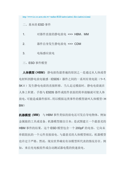
.tw/~mdker/ESD/index/index1.files/index1A.html二、基本的ESD事件1. 对器件直接的静电放电<=> HBM、MM2. 器件自身发生静电放电<=> CDM3. 电场感应放电三、ESD事件模型人体模型(HBM)静电损伤最普遍的原因之一是通过从人体或带电材料到静电放电敏感(ESDS)器件之间的一系列有效电阻(1~1. 5KΩ)发生静电电荷的直接转移。
当人走过楼面时,静电电荷就在人体上积累。
手指与ESDS器件或组件表面的简单接触就可使人体放电,可能造成器件损坏。
用以模拟这类事件的模型就叫人体模型(H BM)机器模型(MM)与HBM事件类似的放电还可发自导电物体,例如金属做的工具或设备。
机器模型源自日本,是试图建立一个最恶劣的HBM事件的结果。
这个ESD模型包含一个200pF的电容,它向未串联阻抗的一个元件直接放电。
与最恶劣的人体模型相比,机器模型也许过于严格。
然而,现实世界确实有该模型所代表的情况存在。
例如,来自充电板组件或自动测试器电缆的快速放电。
带电器件模型(CDM)来自ESDS器件的电荷转移也是ESD事件。
例如,一个器件可能在顺着送料器滑入自动装配机时被充电。
如果它随后接触到插头或其它导电表面,从该器件到金属物体的快速放电就可能发生。
这个事件就是带电器件模型(CDM)事件,对某些器件而言可能比HBM更具破坏性。
尽管放电持续时间非常短暂(通常小于1纳秒),但电流峰值可达几十安培,甚至数百安培。
HBM的分级(ANSI/ESDSTM5.1—2001)表1 ESDS器件敏感度分级——人体模型HBM(ESD STM5.1-1998)MM的分级表2 ESDS器件敏感度分级——机器模型MM(ANSI/ESD-S5.2-1994)CDM的分级电子元器件来料防静电技术要求1 目的和适用范围1.1 目的本要求规定了静电放电敏感电子元器件研制及生产来料检验中受静电放电损害的防护技术要求。
- 1、下载文档前请自行甄别文档内容的完整性,平台不提供额外的编辑、内容补充、找答案等附加服务。
- 2、"仅部分预览"的文档,不可在线预览部分如存在完整性等问题,可反馈申请退款(可完整预览的文档不适用该条件!)。
- 3、如文档侵犯您的权益,请联系客服反馈,我们会尽快为您处理(人工客服工作时间:9:00-18:30)。
for Electrostatic DischargeSensitivity Testing –Charged Device Model (CDM)Component Level™Electrostatic Discharge Association7900 Turin Road, Bldg.3, Suite 2Rome, NY 13440-2069An American National StandardApproved May 2, 2001ESD-STM5.3.1-1999ESD Association Standard Test Methodfor Electrostatic DischargeSensitivity TestingCharged Device Model (CDM) -Component Level Approved September 26, 1999ESD Association™ESD Association standards and publications are designed to serve the public interest by eliminating misunderstandings between manufacturers andpurchasers, facilitating the interchangeability and improvement of products and assisting the purchaser in selecting and obtaining the proper product for his particular needs. The existence of such standards and publications shall not in any respect preclude any member or non-member of the Association from manufacturing or selling products not conforming to such standards andpublications. Nor shall the fact that a standard or publication is published by the Association preclude its voluntary use by non-members of the Association whether the document is to be used either domestically or internationally.Recommended standards and publications are adopted by the ESD Association in accordance with the ANSI Patent policy.Interpretation of ESD Association Standards: The interpretation of standards in-so-far as it may relate to a specific product or manufacturer is a proper matter for the individual company concerned and cannot be undertaken by any person acting for the ESD Association. The ESD Association Standards Chairman may make comments limited to an explanation or clarification of the technicallanguage or provisions in a standard, but not related to its application to specific products and manufacturers. No other person is authorized to comment on behalf of the ESD Association on any ESD Association Standard.Published by:Electrostatic Discharge Association 7900 Turin Road, Building 3, Suite 2Rome, NY 13440-2069Copyright © 1999 by ESD Association All rights reservedNo part of this publication may be reproduced in any form, in an electronic retrieval system or otherwise, without the prior written permission of the publisher.Printed in the United States of AmericaISBN: 1-58537-011-8Caution Notice(This foreword is not part of ESD Association Standard Test Method STM5.3.1-1999)iForewordExisting electrostatic discharge (ESD) test models and standards model a charged object approaching acomponent and discharging through the component. However, with the increasing use of automated component handling systems another potentially destructive discharge mechanism, the Charged Device Model (CDM), becomes increasingly important. In the charged device model the component itself becomes charged - usually by sliding on a surface - and is rapidly discharged by (an ESD event) as it approaches a conductive object.Accurately quantifying the CDM discharge event is very difficult, if not impossible, due to the limitations of the measuring equipment and its influence on the discharge itself. The CDM discharge is generally completed in a few nanoseconds, and peak currents of tens of amperes have been observed. The peak current into thecomponent will vary considerably depending on a large number of factors such as: package type and parasitics. The typical failure mechanism for the CDM model, observed in MOS components, is dielectric damage, although other damage has been noted.The CDM sensitivity of a given component is very package dependent. The same integrated circuit (IC) chip in a small outline package (SOP) may be more susceptible to CDM damage than it is in a dual-in-line (DIL) package. ICs in thin small outline packages (TSOP), or a pin grid array (PGA) packages usually have the lowest CDM withstand voltage.Based on results obtained with early CDM testers, which did not necessarily meet the waveforms specified in this standard, components with CDM sensitivities of 500 volts or less proved difficult to handle without damage. Components with CDM sensitivities of 1,500 volts or more did not experience major field problems using proper handling techniques.This document does not apply to the so-called SDM testers: socketed discharge model. Waveform parameters for the 30 pF verification module should be used for guidance only. They may be subject to change in future revisions of this document.This Standard Test Method was processed and approved for submittal to the ESD Association Standards Committee and the Association Board of Directors by the Device Testing Working Group, 5.0.At the time this standard was approved the Working Group had the following members:Koen Verhaege, Chair Sarnoff CorporationJon Barth Barth Electronics Mike Chaine Micron Technology Lou DeChairo Lucent TechnologiesTom Diep Texas InstrumentsLeo G. HenryORYX Instruments CorporationIra Cohen IntelMarti FarrisIntelHugh Hyatt Hyger Physics Bob CareyLucent TechnologiesMark KellyDelphi Delco Electronics SystemsThomas MeuseKeytek Ian Morgan AMDScott JohnsonAMDIn addition the following people made significant contributions to this document:Satoshi IsofukuTokyo Electronics Trading Joseph VeltriFordTerry Welsher Lucent TechnologiesLes AverySarnoff CorporationKarlheinz BockIMECTable of Contents1. SCOPE AND PURPOSE (1)1.1 S COPE (1)1.2 P URPOSE (1)2. REFERENCES (1)3. DEFINITIONS (1)3.1 C HARGED D EVICE M ODEL (1)3.2 CDM ESD TESTER (1)3.3C ONTACT-MODE DISCHARGE (1)3.4 N ON-CONTACT MODE DISCHARGE (1)3.5 C OMPONENT (1)3.6 C OMPONENT FAILURE (1)3.7 E LECTROSTATIC DISCHARGE SENSITIVITY (ESDS) (1)3.8 ESD WITHSTAND VOLTAGE (1)4. ESD COMPONENT CLASSIFICATIONS (1)5. COMPONENT CHARGING AND DISCHARGING METHODS (2)5.1 D IRECT C HARGING M ETHOD (2)5.2 F IELD-INDUCED M ETHOD (2)5.3 D ISCHARGING M ETHODS (2)6. REQUIRED EQUIPMENT (3)6.1 CDM ESD T ESTER (3)6.2 W AVEFORM V ERIFICATION E QUIPMENT (3)6.2.1 Equipment for 3.5 Gigahertz Waveform Measurement (3)6.2.2 Equipment for 1 Gigahertz Waveform Measurement (3)6.2.3 Verification Standard Test Modules for CDM Testing (3)6.2.4 Capacitance Meter (3)7. PERIODIC EQUIPMENT CALIBRATION, TESTER QUALIFICATION, WAVEFORM RECORDS, AND WAVEFORM VERIFICATION REQUIREMENTS (3)7.1 E QUIPMENT C ALIBRATION (3)7.1.1 Verification Modules (4)7.2 T ESTER Q UALIFICATION (4)7.3 T ESTER W AVEFORM R ECORDS - N EW E QUIPMENT (4)7.4 T ESTER W AVEFORM V ERIFICATION (4)8. QUALIFICATION AND VERIFICATION PROCEDURES (4)8.1 CDM ESD T ESTER Q UALIFICATION P ROCEDURE (4)8.2 W AVEFORM VERIFICATION PROCEDURE (5)9. CDM ESDS TESTING TEQUIREMENTS AND PROCEDURES (6)9.1 T EST REQUIREMENTS (6)9.1.1 Handling of Components (6)9.1.2 ESD Stress Test Temperature (6)9.1.3 Recommended Waveform Check (6)9.1.4 Component Static and Dynamic Tests (6)9.2 CDM C OMPONENT C LASSIFICATION T ESTING P ROCEDURE (6)10. CLASSIFICATION CRITERIA (7)11. APPENDIX 1: VERIFICATION MODULES FOR CDM TESTING (11)ii12. APPENDIX 2: DISCHARGE TEST METHOD GUIDANCE (12)12.1 N ON-CONTACT M ODE D ISCHARGE (12)12.2C ONTACT M ODE D ISCHARGE (11)13. APPENDIX 3: RECOMMENDED COMPONENT, VERIFICATION MODULE AND TESTER CLEANING METHOD (13)Table of FiguresF IGURE 1:CDM ESD WAVEFORM FOR THE VERIFICATION MODULES, USING A 3.5 GIGAHERTZ BANDWIDTH MEASUREMENTSYSTEM (8)F IGURE 2:CDM ESD WAVEFORM FOR THE STANDARD VERIFICATION MODULES USING THE ONE GIGAHERTZ BANDWIDTHMEASUREMENT SYSTEM (9)F IGURE 3:30 P F VERIFICATION MODULE WITH 26 MM DISK (11)F IGURE 4:4 P F VERIFICATION MODULE WITH 9 MM DISK (11)Table of TablesT ABLE 1 - CDM ESD C LASSIFICATION L EVELS (2)T ABLE 2 - ESD S TEP S TRESS L EVELS (5)iiiESD Association Standard Test Method ESD-STM5.3.1-1999 ESD Association Standard TestMethod for Electrostatic DischargeSensitivity Testing -CHARGED DEVICE MODEL (CDM), COMPONENT LEVEL1. Scope and purpose1.1 ScopeThis standard establishes the procedure for testing, evaluating and classifying the electrostatic discharge (ESD) sensitivity of components to the defined charged device model (CDM).1.2 PurposeTo establish a correlatable test method that simulates CDM failures and provides reliable and repeatable results from tester to tester. This will allow accurate comparisons of component CDM ESD sensitivity levels.2. ReferencesEOS/ESD-ADV1.0, Glossary of Terms13. DefinitionsFor the purposes of this standard the following definitions shall apply in addition to those specified in the ESD Association Glossary of Terms.3.1 Charged Device ModelA model that approximates the discharge event that occurs as a charged component discharges to another object at a different electrostatic potential.3.2 CDM ESD testerEquipment (referred to as "tester" in this standard) that simulates the component level Charged Device Model ESD event using thenon-socketed test method.1 ESD Association, 7900 Turin Road, Bldg 3, Ste 2, Rome, NY, 13440-2069, 315-339-6937 3.3 Contact-mode dischargeAn ESD event initiated within a relay. The relay is connected to the component pin via a probe, and the component is not in a socket.3.4 Non-contact mode dischargeAn ESD event that is initiated by a probe tip approaching a component pin and the component is not placed in a socket.3.5 ComponentAn item such as a resistor, diode, transistor, integrated circuit or hybrid3.6 Component failureA condition in which a component fails to meet one or more specified static or dynamic data sheet parameters.1. Static parameters are those measured withthe component in a non-operating (standby)condition. These parameters may include,but are not limited to: input leakage current,input breakdown voltage, output high and low voltages, output drive current, and supplycurrent.2. Dynamic parameters are those measuredwith the component in a functioning(operating) condition. These parameters may include, but are not limited to: fullfunctionality, output rise and fall times undera specified load condition, and dynamiccurrent draw.3.7 Electrostatic discharge sensitivity (ESDS) The ESD level that causes component failure. 3.8 ESD withstand voltageThe maximum ESD level that does not cause component failure.4. ESD Component ClassificationsESD sensitive components are classified according to their ESD withstand voltage using the test procedure described in this standard. The CDM ESD component classification levels are shown in Table 1.1ESD-STM5.3.1-1999 2Table 1 - CDM ESD Classification Levels Class Voltage range C1 <125 vC2 125 v to <=250 v C3 250 v to <=500 v C4 500 v to <=1000 v C5 1000 v to <=1500 v C6 1500 v to <=2000 v C7 =>2000 vNote 1: Use the "C" prefix to indicate a CDM classification.Note 2: Add the following Suffix codes:c = contact moden = non-contact mode For example:C4n: CDM, class 4, non-contact mode5. Component Charging and Discharging MethodsEither of the following two methods may be used to raise the component potential for the subsequent CDM discharge.5.1 Direct Charging MethodThe component to be tested is placed on the ground plate and charged through the pin which best provides an ohmic connection to thesubstrate or bulk material of the component, or through all pins simultaneously. The total charging resistance shall be at least 100 megohms. To prevent component damage,precautions shall be taken to ensure the charging mechanism and component are at groundpotential prior to the initial connection. At least one megohm of the charging resistance shall be physically placed close to the charging pin to isolate the effect of any residual charge on the charge up line. Contact to the charging pin(s) must be established before the voltage is raised. Each pin is discharged, one at a time (including power supply pins and ground pins), except the pins connected to the substrate. Re-charge the component after each pin has been discharged. It is permissible to leave the charging probe on the charging pin during the discharge cycleprovided the waveform requirements of Section 7 are satisfied.Note 3: The substrate, or bulk material, is typically called Vss, or ground, for NMOS or for n-well (p-substrate) CMOStechnologies; and Vcc, or Vdd, for p-well (n-substrate) CMOS technologies. For a charge-pumped substrate (where there is no direct access through an external pin), the Vss or ground pin is still appropriate to use.5.1.1 Multi-chip modules or other specialcomponents (e.g., Silicon on Sapphire, Silicon on insulator, and hybrids) must be charged through a common power supply pin or simultaneously through multiple pins to ensure the entire component reaches the charging potential.5.1.2 If the process technology is unknown,charge the component through the Vss or ground pin, or through all pinssimultaneously. Make note of the charging pins when reporting the results. Vpp pins shall never be used as charging pins, unless all device pins are simultaneously contacted and charged.5.2 Field-induced MethodPlace the component to be tested on the charging plate. Raise the potential of the component by energizing the field charging plate. Discharge through all pins, including Vcc and Vss, one at a time. The size of the field charging plate, at least 7 times larger in area than the size of the component under test, shall be such that the waveform qualification meets the requirement of Section 7. The total source resistance of the charging plate shall be at least 100 megohm. The thickness of the dielectriccovering the charge plate shall have a maximum thickness of 130 microns as the presence of the dielectric reduces the package capacitance between the component and the charging plate which affects the discharge current. Take precautions to ensure components are not charged prior to testing.5.3 Discharging MethodsBackground information on discharging methods is given in Appendix 2.ESD-STM5.3.1-199936. Required Equipment6.1 CDM ESD TesterEquipment meeting the requirements of this standard, producing pulses meeting thewaveform characteristics specified in figure 1 and figure 2.Note 4: Minimize parasitics in the charge and discharge paths whenconstructing test equipment. Parasitics greatly influence test results.6.2 Waveform Verification Equipment6.2.1 Equipment for 3.5 Gigahertz Waveform Measurement6.2.1.1 Oscilloscope - An oscilloscope ortransient digitizer with a single shot 3 dB-bandwidth of at least 3.5 gigahertz (e.g., an Tektronix SCD 5000 or equivalent) with a nominal 50 ohm input impedance.6.2.1.2 Attenuator - with a precision of 0.1 dB at3.5 gigahertz a DC precision of the attenuation factor of 5% and an impedance of 50 ±3 ohms.6.2.1.3 Probe - An inductive current transduceror coaxial resistive probe of at least 5 gigahertz bandwidth.6.2.1.4 Cable assemblies - Cable assemblieswith no more than 0.4 dB loss at frequencies up to 3.5 gigahertz and impedance of 50 ±2 ohms. 6.2.2 Equipment for 1 Gigahertz Waveform Measurement6.2.2.1 Oscilloscope - An oscilloscope ortransient digitizer with a single shotbandwidth of at least one gigahertz.(e.g., a Tektronix SCD 1000, or Tektronix 7104, or equivalent) with a nominal 50 ohm input impedance.6.2.2.2 Attenuator - Attenuator with a precisionof ±0.1 dB at 1.0 gigahertz, a DCprecision of the attenuation factor of 5% and an impedance of 50 ±3 ohms.6.2.2.3 Probe - An inductive current transduceror coaxial resistive probe of at least 5 gigahertz bandwidth.6.2.2.4 Cable Assemblies - Cable assemblieswith no more than 0.1 dB loss at frequencies up to 1.0 gigahertz and impedance of 50 ±2 ohms.6.2.3 Verification Standard Test Modules for CDM TestingTwo gold-plated or nickel-plated etched copper disks on single sided 0.8 millimeter thick FR-4 circuit board material. Each disk shall be etched in the center of a square of material at least 30 millimeters by 30 millimeters. The larger disk shall have a capacitance of 30 pF ±5% at 1 megahertz (approximately 26 millimeters in diameter). The smaller disk shall have a capacitance of 4 pF ±5% at 1 megahertz(approximately 9 millimeters in diameter). The capacitance is measured with the non-metallized non-disc side of the verification modules in intimate contact with the metal surface of a ground plane. The verification modules are shown in Figures 3 and 4 (see Appendix 1).Note 5: I t is very important that the verification standard test modules are compliant with the specifications in section 6.2.3. Therefore, one must measure the capacitance at 1MHz as specified. If the modules do not comply, they can not be used.6.2.4 Capacitance MeterCapacitance meter with a resolution of 0.2 pF, a measurement accuracy of 3%, and ameasurement frequency of one megahertz.Note 6: The sampling rate of a digitized sampling oscilloscope may affect the waveform.7. Periodic Equipment Calibration,Tester Qualification, Waveform Records, and Waveform Verification Requirements7.1 Equipment CalibrationCalibrate all equipment used for tester or waveform verification in accordance with the manufacturers' recommendations, with aESD-STM5.3.1-1999 4maximum of one year between calibrations. This equipment list includes oscilloscope, attenuator, current transducer, coaxial resistive probe, capacitance meter, and calibration module(s) conforming to the requirements of 6.2. Calibration shall be traceable to national standards, such as National Institute ofStandards and Technology (NIST) in the United States, or international standards.7.1.1 Verification Modules7.1.1.1 Place the non-metallized non-disc sideof the 4 pF verification module inintimate contact with the metal surface of a ground plane. Ensure there is no air space between the module and the ground plane.7.1.1.2 Measure the capacitance of the moduleto the ground plane using thecapacitance meter. The capacitance value of the verification module shall be within the value specified in 6.2.3.7.1.1.3 Repeat from 7.1.1.1 using the 30 pFverification module on the ground plane.7.1.1.4 Measure the capacitance of the moduleto the ground plane using thecapacitance meter. The capacitance value of the verification module shall be within the value specified in 6.2.3.7.2 Tester QualificationPerform the CDM ESD tester qualification as part of the initial acceptance testing and routinely as suggested by the manufacturer. Themaximum period between full qualification tests shall be one year. In addition, repeat qualification testing whenever the equipment is serviced in a manner which the manufacturer or user defines as having the potential for modifying discharge current waveforms. The CDM ESD tester qualification procedure is specified in 8.1. Periodic waveform verification shall be performed in accordance with 7.4.Note 7: Due to the high cost of the waveform monitoring equipment,manufacturer certified discharge heads may be used and waveform verification performed using a lower bandwidth monitor as specified in 6.2.2.7.3 Tester Waveform Records - New EquipmentRecord positive and negative waveforms (using either photographs or digitized waveforms)during the tester initial qualification procedures. Waveform records are required for charge levels as defined in the tester qualification procedure. Retain the waveform records until the next calibration or for the duration specified by the internal record keeping procedures.7.4 Tester Waveform VerificationVerify and record the ESD tester waveforms periodically, using the verification modules defined in 6.2.3. The maximum time between verifications shall be one month for equipment that is in use for at least 30 hours per week, or up to three months for testers used lessfrequently. Verification shall include waveform observations and comparison to waveformrecords for both positive and negative polarities. The waveform verification procedure is given in 8.2.Dielectric layers and discharge contacts (e.g., pogo pins) are key elements of the testerconstruction. Any change to these requires tester waveform verification.8. Qualification and Verification ProceduresFor the purpose of both equipment qualification and waveform verification, the standardverification modules are treated as components.8.1 CDM ESD Tester Qualification ProcedureCDM ESD tester qualification shall ensure waveform integrity of the discharge current for both positive and negative polarities, and each verification module specified in 6.2.3. Monitor the waveform using the full bandwidthoscilloscope, attenuator, current probe or coaxial resistive probe described in 6.2.1. Do not use the one-gigahertz monitoring equipment for tester qualification.8.1.1 Clean the verification modules. Avoid skincontact with the modules prior to andduring testing. A recommended procedure is described in Appendix 3.8.1.2 Clean tester components to remove anysurface contamination that could result incharge loss. Pay particular attention to thedischarge probe, charging probe, and theground plane on which the device isplaced. A recommended procedure isdescribed in Appendix 3.8.1.3 Place the 30 picofarad (pF) verificationmodule on the ground plane or chargingplate, ensuring intimate contact (no airspace) between the module and theground plane. When a dielectric layer isused for component testing, it must meetthe requirements specified in section 5and be present during the calibrationprocedure.8.1.4 Set the horizontal time scale of theoscilloscope to 0.5 nanoseconds perdivision. Set the oscilloscope verticalsensitivity and offset, using attenuators ifnecessary, to cover the center 80% of thefull scale deflection.8.1.5 Raise the potential of the module, orcharging plate, to positive 500 volts.8.1.6 Discharge the module with the dischargeprobe close to the center of the verificationmodule and record the discharge currentwaveform. All parameters shall be withinthe limits specified in figure 1. Record thewaveform.8.1.7 Repeat the procedure given in 8.1.5 and8.1.6 at least two more times. Save therecord for future verifications. (Record alland save the one closest to the mean forfuture verification.)8.1.8 Repeat the procedure given in 8.1.5through 8.1.7 using a negative 500 voltcharging potential.8.1.9 For the 4 picofarad verification module,repeat 8.1.4 through 8.1.8 using all thevoltage levels in table 2. If the maximumpotential of the tester is lower than 2000volts, use that as the maximum. Set theoscilloscope vertical sensitivity and offset,using attenuators if necessary, to coverthe center 80% of the full-scale deflectionfor each voltage level. All parameters shallbe within the limits specified in figure 1.Save these records for future verifications. 8.1.10 I t is recommended that all waveformrecords be supplied with the tester forfuture waveform verification purposes. Table 2 - ESD Step Stress LevelsLevel Charging Voltage1 125 v2 250 v3 500 v4 1000 v5 1500 v6 2000 v8.2 Waveform verification procedureWaveform verification shall ensure waveform integrity of the discharge current, as specified in this standard, for both positive and negative polarities, using the small 4 pF verification module specified in 6.2.3.If the one-gigahertz bandwidth monitoring equipment will be used for future waveform verification, repeat the CDM ESD tester qualification procedure using the one-gigahertz bandwidth oscilloscope. Record the waveforms for future comparison purposes during waveform verification.8.2.1 Clean the 4 pF verification module. Avoidfurther skin contact with the module priorto and during testing. A recommendedprocedure is described in Appendix 3.8.2.2 Clean the tester to remove any surfacecontamination that could result in chargeloss. Pay particular attention to thedischarge probe, charging probe, theground plane on which the device isplaced. A recommended procedure isdescribed in Appendix 3.8.2.3 Place the 4 pF verification module on theground plane or charging plate, ensuringintimate contact (no air space) betweenthe module and the ground plane. When adielectric layer is used for componenttesting, it must meet the requirementsspecified in section 5 and be presentduring the calibration procedure.8.2.4 Set the horizontal time scale of theoscilloscope to 0.5 nanoseconds perdivision, and set the vertical sensitivity toallow for approximately ten amperes fullscale deflection.8.2.5 Raise the potential of the module, orcharging plate, to positive 500 volts.8.2.6 Discharge the module and observe thecurrent waveform. All parameters shall bewithin the limits specified in figure 1 if the3.5 gigahertz waveform monitoringequipment is used. If the narrowerbandwidth waveform monitoringequipment is used, ensure that allparameters are within the limits specifiedin figure 2. It is recommended that thewaveform parameters be compared to theprevious satisfactory verification record.Changes in the shape of the dischargepulse, even though they are withinspecification, may indicate degradation ofthe discharge path.8.2.7 Repeat the procedure given in 8.2.5through 8.2.6 using a negative 500 voltcharging potential and evaluate thewaveform.8.2.8 Remove the verification module.9. CDM ESDS Testing Requirements and Procedures9.1 Test requirements9.1.1 Handling of ComponentsUse ESD prevention procedures before, during and after testing.9.1.2 ESD Stress Test Temperature Stabilize the component to room temperature prior to and during the ESD stress testing period.9.1.3 Recommended Waveform CheckAt the beginning and end of each shift during which testing is performed, ensure waveform integrity for the discharge head for the 500 volt level of table 2, for positive and negative polarities, using the 4 pF verification module. If the waveforms no longer meet the specified limits (see figure 1 or figure 2), all test results subsequent to the previous satisfactory check shall be considered invalid. If testing is performed in consecutive shifts, waveform checks at the end of one shift may also serve as the initial checks for the following shift. 9.1.4 Component Static and Dynamic TestsPerform, full static and dynamic testing to specified component data sheet parameters prior to and following ESD stress testing to determine whether components have failed.Note 8: While pin leakage current may beused as a guide in determining the ESDwithstand voltage, it is not an adequatecriterion of component failure for complexintegrated circuits.Note 9: Static and dynamic testingimmediately following the ESD stressingprovides worst-case test data results. Withsome components, static and dynamiccharacteristics may be out of specified datasheet limits when tested immediatelyfollowing ESD stressing, but drift towardsacceptable levels with time. If static anddynamic testing is delayed, the componentmay be improperly classified at a higher ESD withstand voltage.Note 10: If static and dynamic testing is tobe performed at several temperatures,perform the tests first at the lowesttemperature, followed by the increasingtemperatures in sequence.9.2 CDM Component Classification Testing ProcedureClassify components according to their CDM ESD withstand voltage as shown in table 1. Stress test the components according to the procedure below. Testing may be initiated at any level desired. If the component fails, continue testing at a lower voltage until the withstand voltage is found. If the component passes at the initial level, continue testing following the voltage levels specified in table 2 until the component fails or the maximum charge voltage is reached. CDM ESD classification testing shall be considered destructive, even if the component does not fail during testing. Smaller voltage level increments may be used to determine withstand voltage if desired.Note11: A change in componentpackage, manufacturing processes,design, or materials may requirecomponent reclassification according tothis standard. Even if the same chip isused in a different package it should berequalified; no generic qualificationsshould be allowed.。