发电机安装使用维护说明书 英文
FDSL 系列小型风力发电机 用户安装使用手册说明书

FDSL系列小型风力发电机用户安装使用手册FDSL series small wind generators User installationmanual2致用户首先我们感谢您购买、使用我公司生产的小型风力发电机,并为能向您提供产品和服务而感到自豪。
我们建议您在安装、使用FDSL系列小型风力发电机前,详细阅读本《用户安装使用手册》,以保证您更加熟悉产品、并进行正确地安装、连接及使用。
请妥善保管本《用户安装使用手册》以备将来查阅。
本《用户安装使用手册》的编制依据GB/T19068.1-2003《离网型风力发电机组第1部分:技术条件》、GB9969.1-1998《工业产品使用说明书总则》和JB/T5995-1992《工业产品使用说明书机电产品使用说明书编写规定》的有关要求。
3To consumerFirstly, we are thankful for your purchasing, using our products -the small wind generators, and we are proud of being able to provide you with the products and servicesRead this "user installation and use handbook.” carefully before you install or use the product.Please keep this "user installation using manual” properly for future reference.This handbook is based on GB/T19068.1-2003”from the nets type WTG part 1: technical conditions”, GB9969.1-1998 "industrial product manuals general "and T5995-1992 "JB/industrial product manuals electromechanical products instructions written provisions of relevant requirements.4目录致用户 (3)1 产品组成、特点和用途 (7)2产品规格 (7)3产品的使用环境 (7)4 工作原理 (9)5装箱清单 (10)6安装步骤 (11)7 接线流程 (13)8使用注意事项 (14)9特别提示 (15)10常见故障排除指南 (16)11 定期检查 (17)12特别声明 (18)13风力等级表 (19)5ContentsTo consumer (3)1 the product composition, characteristics and uses (7)2 product specification (7)3 Product use environment (7)4 Working principle (9)5 Packing list (10)6 Installation steps (11)7 Wiring process (13)8 using cautions (14)9 Special hints (15)10 Common trouble shooting guides (16)11 Regular inspection (17)12 Especially declare (18)13 Wind rating table (19)6SLM型水平轴小型风力发电机用户安装使用手册1产品组成、特点和用途FDSL系列小型风力发电机是一种水平轴风力发电机,主要由风叶、永磁式发电机、集流转向装置、尾翼连杆和尾翼、整流桥、控制器、逆变器等部分组成,适合在风力资源较好、市电保证不便的地区或场合使用,如海岛、边防哨所、牧场、农场、通讯基站、风光互补、野外作业等,根据风力资源的情况可以部分或完全取代市电,满足在其额定输出功率范围内各种用电器的用电要求,具有工作噪声低、使用免维护、可靠性高、安装架设方便、工作寿命长等特点。
600MW级汽轮发电机安装说明书C版
INSTALLATION MANUAL FOR 600MW/660MW/680MWTURBINE GENERATOR600MW/660MW/680MW汽轮发电机安装说明书Document No.(文件号) : AQ-9Document Code:文件编码AQ-9Rev. CDongfang Electric Machinery Co., Ltd. 东方电气集团东方电机有限公司2012-09-24REV. CINSTALLATION MANUAL FOR 600MW /660MW/680MW TURBINE GENERATOR AQ-9DONGFANG ELECTRIC MACHINERY CO., LTD. 第 1页Contents 目录CHAPTER 1: GENERAL第一篇:总论1. Site Check, Acceptance and Storage for Equipment ………………………… 设备的清点验收及现场保管2. Preparation and Requirement for Installation ……………………………………安装前的准备工作及施工要求3. Weight List for Major Parts (estimated)………………………………………… 主要起吊零部件重量(粗略值)4. Installation Flow Chart …………………………………………………………… 安装流程图CHAPTER 2: PROCEDURE FOR INSTALLATION第二篇:分部安装说明 1. Making of Flowable Grout Pads & Installation of Foundation Plate …………… 浮动水泥墩的灌浆制作及基础板的安装2. Assembly of Stator …………………………………………………………………定子装配3. Inspection of Hydrogen Cooler ……………………………………………………氢气冷却器的安装4. Stator Teminal Assembly ……………………………………………………………定子出线装配5. Preliminary Centering of Stator ……………………………………………………定子初找中心6. Insertion of Rotor ……………………………………………………………………穿转子7. Installation of Bearing ………………………………………………………………发电机轴承安装8. Measurement of Air-gap between Stator and Rotor ………………………… 定、转子空气隙的测量9. Installation of Fan ……………………………………………………………………风扇装配10. Installation of Upper End Bracket and Centering of Generator ………………发电机的封盖、找正及定位11. Installation of Oil Gland Seal and Deflector ……………………………………油密封及挡油盖装配12. Generator Air Leakage Test ………………………………………………… 发电机整体试验13. Final installation of Bearing …………………………………………………………轴承总装配2 3 4 1012 14 31 33 37 39 46 49 50 52 58 6975INSTALLATION MANUAL FOR 480MW GAS TURBINE GENERATOR AQ-9DONGFANG ELECTRIC MACHINERY CO., LTD.第 2页14. Installation of Brush Holder & Steady Bearing …………………………………碳刷架及稳定轴承安装15. Inspection and Test Before Starting ……………………………………………启动前的检查与试验Fig.1-6 Figures for Inserting Rotor ………………………………………………… 图1-6穿转子示意图CHAPTER 3: QUALITY CONTROL RECORD OF GENERATOR 第三篇:发电机质量控制记录QCR1001~5003………………………………………………………………………76 81 8698-134INSTALLATION MANUAL FOR 600MW/660MW/680MWTURBINE GENERATOR600MW/660MW/680MW 汽轮发电机安装说明书CHAPTER 1: GENERAL第一篇:总论This installation manual is applicable to “600MW/660MW/680MW” turbinegenerator supplied by DFEM. Three types of stator are distinguished as follows according to their structure and mode of transportation.本安装说明书用于东方型600MW/660MW/680MW 汽轮发电机,按照定子结构形式和运输方式可分为如下3种类型: ¾ Single-stator整体定子结构Description: For this type of stator, the stator should be transported as a single one.描述:对于此种结构的定子,定子作为一个整体进行运输。
EG系列发电机使用维护手册(中文)

REV 1.0/0607ENGGAThree-phase Synchronous Generators 三相同步发电机Operation & Maintenance Manual安装和维护手册安全指南EG发电机采用最新的发电机设计、生产工艺、质量控制理念,拥有出众性能、可靠质量、优质发电机。
敬请各位用户在使用前务必仔细阅读和理解本手册中有关发电机安装、使用和维护的内容。
安装、调试、检修必须由具备相关工作资格的专业人员进行,操作人员应能掌握正确的使用方法、安全操作,否则有可能引起严重的人员伤亡或设备损坏事故。
①警示标识本手册中使用和随发电机提供的警示和警告标识的含义如下,发电机组配套商应确保警示标签位置放置正确并清晰,标签含义如下:A.普通警告标识,可能会导致人员伤亡、设备损坏的危险B.电气危险标识,可能电气原因会导致人员伤亡的直接危险C.通用危险标识,可能会导致人员伤亡的直接危险② 发电机警告标签的位置目录1 概述1.1 标准1.2 发电机型号代表意义1.3 铭牌1.4 接收检查及储存2 发电机的使用环境2.1 使用环境2.2 发电机的容量修正3 发电机结构3.1 发电机的工作原理3.2 定子3.3 转子3.4 励磁系统4 安装4.1 安装环境4.2 安装4.3 转向4.4 接线4.5 接地、保护5 运行5.1 运行前的检查5.2 运行前的试验调整5.3 开机与停机5.4 并联运行6 维护和检修6.1 一般维护6.2 检修项目6.3 发电机的拆装6.4故障现象及排除6.5 A VR故障检修7 结构图结构图零件表本安装使用维护手册阐述了英格EG系列交流发电机的结构特点、性能原理、安装使用和维护检修。
1 概述1.1 标准发电机符合下列国际和相关国家标准:I.E.C 60034-1 国际电工委员会标准BC5000 英国标准NEMA MG21 美国标准C.S.A C22-2 加拿大标准VDE 0530 德国标准GB755 中国标准1.2 发电机型号意义:EG发电机的型号按照以下方式命名例如:EG280S—120NEG---表示EG系列发电机280---表示发电机的机座号(160、225、280、315、355、400、500)S---表示机座的长短(M、L)120---表示发电机的容量带,KWN---表示发电机的改进、用途,N---新改进的NEW系列;H---船用系列;B---变形产品1.3 铭牌发电机铭牌位于驱动端右侧机体上。
发电机组说明书
MOTOYAMA Titanium Series Professional Power GeneratorOWNER’S OPERATING MANUAL TM1800/TM1800ETM2800/TM2800ETM3800/TM3800ETM4800/TM4800ETM5800/TM5800ETM6800/TM6800EPREFACEThank you for purchasing MOTOYAMA Titanium Series gasoline generatorWe want to help you get the best results from your new generator and to operate it safely. This manual contains the information on how to do that, please read it carefully. This owner’s manual describes the operation and maintenance of the MOTOYAMA Generator. All the information in this publication is based on the latest product information available at the time of printing. MOTOYAMA reserves the right to make changes at any time without notice and without incurring any obligation. No part of this publication may be reproduced without written permission. This manual should be considered a permanent parts of the generator and should remain with it if it is unsold.IMPORTANT NOTICESPlease pay special attention to statements by the following words:△WARNINGA warning is used to alert the user to fact that hazardous operating and maintenance procedures may result in injury to or death of personnet if not strictly observed.CAUTIONA caution is used to alert the user to fact that hazardous operating and maintenance procedures may result in damage to or destruction of equipment if not strictly observed.NOTEA note is used to give helpful information.This manual should be considered as a permanent part of the unit and should remain with the unit when resold.Contents1 Generator Safety (4)2 Introduction to Parts and Components (6)3 Pre-Operating Inspection (7)4 Starting the Engine (11)5 Service (13)6 Stopping the Engine (18)7 Maintenance (19)8 St orage (23)9 Troubleshooting (25)10 Assembly of parts (27)11 Specifications (29)12 Wiring D iagram (30)App endix Warranty Evidence (34)1 GENERATOR SAFETY1.1 Never operate it in an enclosed room(Fig.1) . 1.3 Never connect it to home circuit(Fig.3).1.2 Do not operate it under wet circumstances1.4 Place inflammables away from the unit (Fig.2).at least one meter(Fig.4).1.5 No smoking when filling fuel(Fig.5).1.6 Do not spill out when filling fuel(Fig.6)1.7 Always fill fuel after stopping it(Fig.7)2 INTRODUCTION TO PARTS AND COMPONENTSMain components of the unit are located as follows :Fig. 71. Fuel sensor 9. Starting handle2. Fuel filler cap 10.Fuel cock3. AC plug socket 11.Air cleaner4. AC breaker 12.Chock lever5. Voltmeter 13. Ground terminal6. Dipstick 14.Muffler7. Ignition switch 15.Spark plug8. Drain plug3 PRE-OPERATING INSPECTION3.1 ENGINE OIL LEVELNOTE: Always check the generator in the case of stopping the generator on a level ground.3.1.1 Turn out the oil 3.1.3 In the case thatfiller cap and clean the the oil level is belowdipstick with a clear the lower level markcloth(Fig.9) of the dipstick, fill oilto the upper level markof the dipstick(Fig.11)3.1.2 Insert the dip-stick back into the oilfiller hole withoutturn ing it in(Fig.10) 3.1.4 Reinstall the oilfiller cap well(Fig.12)3.2 FUEL LEVEL3.2.1 Open the fuel filler cap (Fig.13)3.2.3 Fill fuel to the shoulder of the fuel (Fig.15)3.2.2 Check the fuel level, and fill fuel if necessary(Fig.14) 3.2.4 Reinstall the fuel filler cap well(Fig.16)3.3 AIR CLEANER3.3.1 Remove the air cleanerhousing (Fig.17) 3.3.4 Put the filter element intothe original position, install the 3.3.2 Check and makecover and secure it well(Fig.19)sure the air cleaner coreis intact and clean.If itis broke,replace it with anew one.3.3.3 If the core is filthy,Clean it in the followingSequence(Fig.18)a) Clean the core in thecleaning solvent.b) Dry it upc) Dip a few drops of en-gine oil into it.d)Squeeze excess oil.5GF-4) 3.4 BATTERY(only for 4GF-4&Check and make sure that theelectrolyte level of each battery cell is between is upper and lower levelmarks(Fig.20).1.upper level mark2.lower level mark4 STARTING THE GENERATOR4.1 Remove all loads from AC socket. 4.4 Set the choke lever to OFF position (Fig.23)4.2 Switch off the AC breaker(Fig.21)Don’t close the choke when starting th e engine in hot condition.4.3 Turn on the fuel cock(Fig.22)4.5 Turn on the ignition switch(Fig.24) 4.7 Once the engine is warmed up, set the choke lever to ON position (Fig.26)4.6 Pull the start handle gentling until feeling an anti-action,and then pull it up strongly(Fig.25). △WARNINGAfter starting up, release the starting lever slightly so avoid injuring personnel or damaging equipment due to its bouncing back.5 SERVICEAlways do as the following as to keep the generator in a sound condition. △WARNING5.1 Always connect the generator to the earth to preventmisusing(Fig.27)5.2 The following table gives reference information for connecting electric appliances to the generator.5.3 If the generator is to supply two or above loads with power supply, be sure to connect them one by one with higher start current first(Fig.28).5.4 Connencting methods are illustrated as follows(Fig.29).a)Correctc)Correctb)Fobidden△WARNINGWhen connect the generator to home power supply,be sure that a skilled electrician does this job.Improper connecting between the generator and loads may cause damage to the generator,even a fire.5.5 USE INSTRUCTION WHEN PROVIDING ALTERATIVE CURRENT SUPPLY5.5.1Start the generator (Fig.30). 5.5.3 The unit is able to supply 110/220V.Setthe voltage selector to position suitabletoequipment(Fig.32).5.5.2 Connect devices(Fig.31). 5.5.4 Swith on the AC breaker(Fig.33).6 STOPING THE ENGINE6.1 Switch off the ACbreaker(Fig.34) 6.3 Set the fuel cock to OFF(Fig.36)6.2 Turn the ignition switch to OFF (Fig.35).To stop the generator in an emergency,Turn the ignition switch to OFF.MAINTENANCEUser should service the unit according to the maintenance schedule as follows:7.1REPLACEMENT OF ENGINE OIL7.1.1 Turn and then take out the dipstick(Fig.37).7.1.2 Unscrew the drain plug, and empty the engine oil from the crankcase.7.1.3 Screw on the drain plug(Fig.38).7.1.4 Fill engine oil to the upper level mark of the dipstick.Engine oil recommended:4-stroke gasoline oil-engine oil class SE,SF from API Srviceclassification or SEA 10W-30 engine oil equivalent to Class SG.7.1.5 Fit the dipstick to the original position.7.2 SPARK PLUG7.2.1 Withdraw the 7.2.2 Dismantle the spark 7.2.4 Check the spark plug capSpark plug cap front the plug by means of a special and adjust if necessary.The cap Spark plug(Fig.39). tool(Fig.40). should be 0.7-0.8mm(Fig.42).7.2.3 Clear away carbon fouling around the spark7.2.5 Reinstall the spark plug and plug(Fig.41).cap well(Fig.43).Spark plug recommended:F6RTC7.3 MAINTENANCE OF FUEL FILTER CUP7.3.1 Set the fuel cock to OFF,and disdmantle7.3.3 Fit the fuel filter cup and gauze to the the fuel filter cup and gauze(Fig.44).original position(Fig.45). 7.3.2 Fit the fuel filter cup and gauze to theoriginal position.8 STORAGEDuring long-term storage of the unit which are not kept in use. Carry out procedures as follows:8.1 Empty the fuel from the fuel tank(Fig.46)8.2 Having wash the fuel cup and gauze,Install them to the original position.8.4 Turn off the oil filler cap and oil drainplug ,and the empty the engine oil from thecrankcase(Fig.48).8.3 Discharge the fuel from the carburetor(Fig.47).8.5 Reinstall the oil drain plug,fill engine oil to 8.6 Pull up the starting handle gently The upper level mark of the dipstick,followed until an anti-action(Fig.50).by fitting the oil filler cap to the original pod-sition(Fig.49).8.7 Place the generator set in the cleanarea(Fig.51).9 TROUBLESHOOTING9.1 TROUBLE: the generator fails to 9.1.3 Check the fuel inside tank(Fig.55). Start(Fig.52).9.1.4 Remove the spark plug, and check 9.1.1 Check to see if the ignition switch it for proper sparks(Fig.56).is at ON(Fig.53).9.1.5 If the generator set is still out of work, see your dealer for help(Fig.57).9.1.2 Check engine oil level(Fig.54)9.2 TROUBLE: the unit fails to generate electricity.9.2.1Check the light bulb(Fig.58).9.2.2 Check to see if the AC breaker is at ON(Fig.59).9.2.3 If such check is still unsatisfactory, see your dealer for help(Fig.60).10 ASSEMBLY OF PARTSAssemble the wheels, to this end:10.1.1 Fit the wheel onto the axle,thensecure them with washer and split pin.10.1.2 Mount the assembled axle on the Feame with bolt and nut.Fig.611.Inner side2.Shorter side3.Longer side4. Latch5.Stopping disc6.Engine location7.Retainer 8.Split pin9.Wheel 10.Right axle(close to engine) 11.Left axle(close to generator)12.Nut 13.Bolt10.2 BATTERY(Fig.62)To install the battery,procced as follows: Array 10.2.1 Assemble the battery with nuts,bolts and washers.10.2.2 Connect the starting cable to the starting motor terminal alone the bottom of the fuel tank.10.2.3 Connect the earth line with the rear end of the generator.10.2.4 Connect the starting cable to the positive lead of the battery first,and then to the negative one.Disconnect in the reverse order.Fig.621. Starting motor2. Starting cable3. Protective frame4. Battery bracket5. Battery guard6. retaining frame7. Battery (with a rating of 12V-35Ah)8. Negative wireAPPENDIXINSTRUCTIONS FOR THE WARRANTY CERTIFICATE1. Keep the certificate well.2. Be familiar with the warranty details IMPORTANT NOTEin the certificate. The evidence will be kept as one of the owner’s in-3. When you draw the certificate, pay portent documents,so,be sure to give the evidence to theattention to item in the certificated filled by seller.your seller. TO OWNERS:When purchasing a new product in a seller,be sure to COMMODITIES PURCHASING EVIDENCE read carefully the following in the table and be sure tomake a mark O beside the description which youunderatand,at last,sign your name.Agree with all the details contained in the warrantycertificate and accept them。
电机安装与维护英语作文

电机安装与维护英语作文Electric Motor Installation and Maintenance。
Electric motors are widely used in various industries and play an important role in the production process. However, improper installation and maintenance can lead to motor failure and even accidents. Therefore, it is necessary to understand the correct installation and maintenance methods of electric motors.Installation。
Before installing the electric motor, it is necessary to check whether the motor model, voltage, power, and rotation direction meet the requirements of the equipment. In addition, the installation location should be dry, ventilated, and free of dust, and the ambient temperature should not exceed the rated value of the motor.The installation process should be carried out inaccordance with the instructions provided by the manufacturer. The motor should be placed on a flat surface and fixed with bolts. The alignment of the motor shaft and the equipment shaft should be checked to ensure that they are parallel and concentric.After the motor is installed, it is necessary to check the insulation resistance of the motor winding with a megohmmeter. The insulation resistance value should be greater than the specified value, and the motor should be grounded reliably.Maintenance。
发电机QF18-22安装使用说明书_中英文

QF系列18~22MW汽轮发电机安装使用维护说明书MANUAL FOR18~22MW TURBO-GENERATOROF QF SERIES0JS・461・402 编制 TRANSLATOR: 刘红蕾 校核 CORRECTOR: 薛守栋 李 霖批准 APPROVER:时间D A T E: 2004.6山东济南发电设备厂SHANDONG JINAN POWER EQUIPMENT FACTORY THE PEOPLE’S REPUBLIC OF CHINA目录Content1.概述第 2 页General2.安装地点及使用条件第2 页Installation site and working conditions3.结构说明第 4 页Structure introduction4.安装说明第 12 页Installation5.使用说明第 18 页Operation6.维护检修说明第 26 页Maintenance7.无刷励磁机使用维护说明 第33 页Brushless Exciter type Operation and Maintenance Instruction 8.保证期第 40 页Guarantee period1. 概述本系列汽轮发电机为QF系列18~22MW空冷三相两极交流同步发电机,额定转速为3000r/min,频率为50Hz。
发电机设计为封闭循环通风系统,径向双流式通风系统。
发电机型号:如QF(NW)-18-2型,QF代表空冷汽轮发电机,18代表容量18兆瓦,2-代表2极,N 代表双支点,W代表无刷励磁方式。
本系列发电机有无刷励磁和静止励磁两种励磁方式供选择。
此系列汽轮发电机的旋转方向,从汽轮机端看为顺时针方向。
GeneralAll this series of Air-Cooled turbo-generators are three-phase, two-pole, synchronous generators whose powers range from 18 MW to 22 MW. Their rated speed and frequency are 3000r/min, 50Hz. The design of generators is closed and circular aeration system and radial double-flow aeration system. Generators model: For example QF(NW)-18-2, QF means Air-Cooled turbo-generators, 18 means Power is 18MW, 2 means 2 poles, N means two supports, W means Brushless Exciter type. This series of generators have two Exciter types, brushless exciter and static exciter. All this series of generators clockwise rotate when looking from driving-end.2. 安装地点及使用条件Installation site and working conditions:2.1 安装地点海拔不超过1000米。
5KW离网发电机组安装步骤说明书(英文版)

5KW Off-grid PV GeneratorInstallation InstructionsMay 2014Solar panels BracketControllerBatteriesInverterFirst, the purpose of this manualThis manual provides PV module (hereinafter referred to as "components") the installation and use of information.Before installation, the installer must read and understand this manual, if you have any questions, please contact the company for further explanation. Meanwhile, when install the components , please observe all of this manual safety precautions and local laws and regulations.Before installing solar power systems, installers should be familiar with the mechanical and electrical requirements of this system, please keep this manual for future reference when maintenance or component need to sell or need to be addressed.Second, the GeneralInstallation of solar photovoltaic systems requires specialized skills and knowledge, it must be made by qualified engineers . Each component comes with a permanently attached junction box. For easy installation, the company provides customer demand prefabricated cables. Installers should know in advance the risk of injury (including electric shock and other injuries.) that may occur during the installation, Individual components in direct sunlight can produce more than 30V DC voltage, and the contact voltage above 30V is dangerous.twoDo not disconnect the cable under load conditions.Component can convert light energy into DC energy, component applied to the ground, roofs, vehicle or vessel, and other outdoor environments. Rational design and use of the support structure is a system designer or installer's responsibility.Do not disassemble the assembly, movement or adhere to any part of any nameplate on the assembly.Do not paint or other adhesive on the surface of the component (glass surface).threeDo not use mirrors or lenses to focus sunlight onto the component. When the component installation, shall comply with all local regions and countries relevant laws and regulations , the relevant permit is needed when it necessaryThird, the security processing①Properly package the components before installation .②Hold the junction box can not be directly handling components.③Must not stumble on the component or components in the obstacle falls.④To gently, especially where there are edges.⑤After installation, Do not disassemble components,do not move any part or label of the component.⑥Can not spray paint or other items stuck in the back of the assembly.⑦Not in the component border or drill holes in the glass.⑧Do not put the components into place where not stand or safe.⑨Components broken glass can not continue to use after retirement.⑩Require a clean environment, with dry tool operation.fourFourth, security installation①Do not let children near the installation.②Do not install components in high winds.③Prevent components falling, the site should be used when installing the appropriate operating methods and safety equipment④Avoid currents in the installation, components should be completely cover up.⑤Installing components or assemblies can not touch the cord or wire connection port when exposed to sunlight.⑥In the implementation of security operations can not wear metal jewelry or jewelry.⑦Do not disconnect the line when the circuit or disconnect the wiring plug.Fifth, the installation procedure of solar PV modules1, Clamp installation: clip secured housing on top, in the same direction and at the same horizontal plane.fivesixAs shown in Figures 1:Figure 1 clip2, Purlins Installation: Housing purlins laid on top of the tank on the clamps with screws.As shown in Figures 2 and 3:Figure 2 purlin installationsevenFigure 3 purlin installation3. Harness laying: laying the wiring harness on the roof, set a good size, and fixed it with a tie and purlins .As shown in Figure 4, Figure 5 and Figure 6:Figure 4 panels to the combiner box connectoreightFigure 5 Wiring HarnessFigure 6 Wiring Harness4, Battery installation components:the component is laid on purlins, first laying of top-level components, laying one of the component ,put connector into a pre-laid wiring harness, just for avoid assembly harnessnineconnector caused unnecessary trouble .As shown in Figure 7:Figure 7 Battery Installation5, Briquetting installation: first of all ,put the briquetting into the purlins notch ,tighten the clamp screws and fixed the components in the purlins.As shown in Figure 8 and Figure 9:Figure 8 side briquettingtenFigure 9 briquetting6, Combiner box wiring: The wiring harness laying on combiner box where stay a position in advance, according to the mark of wire line core to put the wire harness into the combiner box, the wiring should be strong and reliable.As shown in Figure 10:Figure 10 components into the combiner box wiringeleven7:Battery installation and wiring: the battery should be placed neatly, using four series connection and five in parallel to made the battery cable connected to combiner box.As shown in Figures 11 and 12:Figure 11 battery pack lead into the combiner box terminalsFigure 12 battery pack to the combiner box wiringSix, product identificationEach component has three identityNameplate: Description Value Model, rated power under standard test conditions, rated voltage, rated current; the weight, size and so on; maximum capacity and maximum system voltage fuses and company information.Barcode: price within each group has a unique serial number, which is permanently fixed to the internal components when the component is laminated into the back of the components will be affixed to the inside of a bar code with the same serial number for easy scanning.Seven, testing, debugging and troubleshootingAll electrical and electronic components should to follow instructions guide books before installations.①Components are connected in series to test the system beforeUse a digital multimeter to check the open circuit voltage in series components. The measurement should be equal to the sum of the individual components of the open circuit voltage. You will find the rated voltage type of component used in the technical specifications. If the measured value is much lower than expected, follow the "low voltage Troubleshooting" instructions for processing.Check the short circuit current of each series circuit, measurement can betwelveperformed by a digital multimeter connected to both ends of the series components measured directly, or use the PV lamps and other loads to have a rough measurement . Note that the scale ammeter or the rated load current rating should be greater than 1.25 times the rated short-circuit current of the series components. You can find the rated current technical specifications used in the model component. Measured value will change significantly with the shading weather conditions, time of occurrence and components.②Low V oltage TroubleshootingIdentification of the normal low voltage and low voltage fault. Normal low voltage referred to herein means a component to reduce the open circuit voltage, which is increased from the temperature of the solar cell or decreased irradiance caused. Failure is usually due to the wrong connect of low voltage terminal or damage caused by bypass diodes. First, check all wiring connections to ensure that there is no open, and has a well-connected.Check the open circuit voltage of each component.With an opaque material completely covered components. Disconnecting both ends of the wire assembly.Remove the opaque material assembly, inspection and measuring the open circuit voltage terminal.thirteenIf the measured voltage is only half the rated value, indicating that the bypass diode is bad, see "Testing and replacing bypass diodes."At the case of the irradiance is not very low if the terminal voltage rating difference of more than 5%, indicating that the component connection is not good.Eight, maintenanceOur company recommends the following maintenance measures to ensure optimal performance components:When necessary, the glass surface of the cleaning assembly. Use a soft sponge or cloth dampened with water for cleaning. You can use a mild, non-abrasive cleaner to remove the dirt.Mechanical and electrical checks regularly every six months to ensure that the component joints clean and reliable connection.If you have any questions, please qualified personnel for inspection. Note that all components comply with the system, such as stents, charging rectifiers, inverters, batteries and other maintenance instructions.Nine, turn off the system1, in order to prevent the generation of electrical conductors dismantling process, you must use an opaque material to cover photovoltaic modules. 2, when the power is disconnected from the system, the various elementsfourteenof the present system should be used in accordance with instructions.3, the system is now shut down and can be removed. During operation, comply with all applicable safety during installation instructions.Ten. DisclaimerDue to the use of this manual and photovoltaic (PV) product safety, operation, use and maintenance of the conditions or methods beyond the control of our company,and our company have no responsibility for any loss or expense with these installation, operation, use or maintenance of the operation .Due to the use of PV products may infringe third-party patents or other rights, it does not belong to the scope of responsibility of our company. Customers are not charged for using the products licensed for use under any patent or patent rights, whether express or implied.The information in this manual is based on knowledge and proven experience in our company, however, these information and advice, including product specifications do not play any warranty, whether express or implied. Our company reservations modify manual, PV products, specifications or product information right and do not need to prior notice.fifteensixteenseventeeneighteennineteentwentytwenty-one。
NOVA混合动力发电机手册和自我维护指南说明书
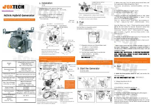
NOVA Hybrid GeneratorManual and Self-maintenance Guide V1.1Weight重量4.0kg(8.8lb)w/o Accessories/5.2kg(11.5lb)Total4kg 不含配件/5.2kg 总重量Generated Output功率1.8kW Continuous/2.0kW Max.Power1.8KW 持续功率/2KW 最大功率Dimension(L x W x H)尺寸(L x W x H )260x 312x 325mm/10x 12x 12in Applicable UAV Types适用机型Multicopters &VTOL Fix-wings多轴旋翼、垂直起降固定翼Max.Take-off Weight适用机型最大起飞重量18kg for Quadcopter 21kg for Hexacopter四轴建议18kg ,六轴建议21kgOutput Voltage适用机型动力电压12S (49V)12S (49V)Fuel Consumption油耗560g/kw ·h (hovering 1.5L/h )560g/kw ·h (悬停1.5升/小时)Service Temperature使用温度环境-20~40°C Altitude使用升限(海拔)2000m1.InstallationInstalling NOVA to UAV,default is lifted way.将NOVA 安装至无人机的合适位置,默认为吊装。
①Firstly mount the fuel tank under drone frame.首先吊装油箱总成。
②Secondly install NOVA under the tank.然后安装发电机。
Unit:mm 单位:mmDefault mounting method is in the lifted way.Other mounting methods may lead to damper failure.出厂默认为吊装,其他安装方式会导致减震器损坏。
- 1、下载文档前请自行甄别文档内容的完整性,平台不提供额外的编辑、内容补充、找答案等附加服务。
- 2、"仅部分预览"的文档,不可在线预览部分如存在完整性等问题,可反馈申请退款(可完整预览的文档不适用该条件!)。
- 3、如文档侵犯您的权益,请联系客服反馈,我们会尽快为您处理(人工客服工作时间:9:00-18:30)。
1 Operation of generator1.1 Preparations before start-up, including:a) Clean the work-yard and the generator set from any debris.b) Check the tightening condition, lock the gasket tightly, tack weld if necessary; keep therotatable parts clean.c) Check the inlet and outlet water pipelines, oil pipelines and valves, in order to know ifthere are leakages and problems of water flow in the pipe.d) Check the level of lubricating oil, oil number, oil quality, water pressure, and recordthe water temperature and ambient temperature.e) Check each connecting cable, to make sure that the joints contact well and withoutrust, connection is right, and the marks are complete and distinct.f) Check if the equipments of high-pressure oil and the brake run normally, and if thebrake pressure can meet the relevant requirements.g) Check the fire extinguishing system and other protecting facilities, to ensure security.h) Check the gaps between rotating parts and stationary parts, especially when there aredimension requirements.i) Make preparation work of recording before start-up.1.2 Initial no-load start-up operationThe time of initial start-up of generator, operating sequence and the general commandershall be determined through consultation among the buyer, the seller and the installationentity.1.2.1 Under the organization of the general commander, the operators and monitors shallget ready.1.2.2 Before start-up, first open the cooling water of the upper and lower oil cooler and aircooler. The temperature of the oil in the oil tank shall not be lower than 100C, andthat in the plastic bush tank shall not be lower than 50C.1.2.3 Push the rotor upward with high-pressure oil, and make the thrust pad lubricate toavoid dry friction.1.2.4 Manually start the generator and let the rotating speed increase to 30% ~ 50% of thenominal speed, so that the oil-bound film can be quickly formed. Let it run for aperiod of time and check the bearing temperature every 1 min., until the value keepsstable. There shall be no sharp increase of bearing temperature. At the same time,monitor the sound and observe every part to see if an abnormity occurs.1.2.5 When the generator running becomes stable and bearing temperature is normal,increase the rotating speed to the nominal speed gradually. Make the detectingrecords timely:a) bearing temperatureb) temperature of inlet cooling water and outlet cooling waterc) oil leveld)vibration of rack1.2.6 If the vibrationg of the generator meets the requirements (otherwise balance test willbe needed), and the temperature of the bearing bush keeps stable, the machine canbe stopped for check.1.2.7 Checking after the generator stopsa) looseness, etc. in the parts of the rotor;b) resetting of the brake;c) Leakage of oil and water, and oil splashing of the upper and lower oil pipe.1.3 Initial on-load run1.3.1 Before the initial on-load run, the approval of relevant authority is needed, and thechecking work of the phase sequence of network and the generator shall be welldone. At the same time, open all the cooling water, and check water pressure andflow, level of lubricating oil, winding of stator and rotor, bearing, etc., and makegood preparation before start-up.1.3.2 Increase exciting current gradually at the nominal rotating speed. Only whengenerator’s voltage, frequency and phase angle meet the requirement of network,synchronize them and switch on, and then increase loads in phases, and at thesame time make good records, like increase of temperature, vibration, etc.1.3.3 If there are no abnormalities, bring the load to rated power, maintain hour running,and check carefully the following items:a) temperature of stator and rotor winding;b) temperature of thrust bearing and guide bearing;c) temperature of inlet and outlet wind;d) vibration of the rack;e) electric spark at the bus rings;f) Excitation data at the condition of no-load and on-load;1.3.4 Set the technical parameters according to relevant technical requirements.2 maintenance of generator2.1 The personnel of operation and maintenance of power station shall know and master thegenerator’s structure and performance, and shall have a certain professional level on theoperation and maintenance of generator, so as to guarantee the normal running of thegenerator. The operator shall record the service data on time, if the following phenomenonoccur, shall stop it and check:a) vibrating and shaking abnormally;b) there is knocking sound;c) bearing temperature increasing suddenly, or oil level rising and loweringd) discontinuance of cooling water;e) temperature of the stator and the rotor rise too much;f) There are abnormal oil mist, smog, empyreuma, etc.2.2 Keep the inside of the generator clean and dry, without dust, oil, water, etc., so that canmake the ventilation and elimination of heat of the motor easier, improve the insulationresistance, and prolong the operating life span of the motor.2.3 Wash periodically the oil tanks of upper and lower rack and the copper pipe cooler, andcheck if there is leakage, in order to guarantee safe operation.2.4 Take samples periodically and test the quality of lubricating oil.2.5 Check the pressure of collector rings, brush yokes and electric brush periodically andobserve the wearing condition of carbon brush and electric spark.2.6 Check the braking system regularly for air pressure, oil pressure and wearing condition ofbraking-shoe.2.7 Check all the connecting cables and joints periodically for looseness, poor contact, etc.causing overheating, rust, etc.2.8 The maintenance of stator includes:a) check insulation resistance of stator coil regularly;b) observe if there is heating at the ends of stator, looseness of the insulating parts,abnormal heating at the joints of stator, and deformation at the ends of winding;c) if there is looseness and abnormal noise of iron core of stator;d) if there is looseness at slot wedge, loose weld between the pressed disc of stator andventilation grid, etc.e) If there are looseness of the fastening parts in the base, or loose weld between thepressed disc of stator and ventilation grid, etc.2.9 The maintenance of rotor includes:a) check periodically if there is deformation of rotor, especially after runaway;b) shall regularly check the insulation resistance of rotor winding to see if there isshort-circuit.c) check the damping bar and damping ring to see if there is loose weld anddeformation.d) check if there are looseness of all the fastening parts at the rotating parts.e) observe if the iron core of magnetic pole is loose, and if the coil of magnetic polemovedf) check if the leading wire of rotor and leading wire between the poles of magnetic coiljoint well and no loose.g) observe regularly the inside of the rotor support, and the space between thelaminations of magnetic yoke to avoid the entry of foreign matters.2.10 The maintenance of generator bearing includes:a) Generally, the temperature of tungsten bearing bush shall be less than 650C, and themaximum temperature can not exceed 700C. The temperature of hot oil in the plasticbearing bush can not exceed 500C, the temperature of the body of thrust bearing bushcan not exceed 550C, during the running of generator, the value of resistancethermometer alarm and set stop value can be 10K~15K and 15K~20K higher thanthe normal running temperature respectively; and not to exceed the above mentionedvalue.b) When start the generator in winter, the oil temperature in the oil tank can not be lessthan 100C. For the plastic bearing bush, start-up is allowed if the oil tank temperatureis 50C and above.c) If not in use for over 48h, before start the generator, push the rotor upward to avoiddry friction and bush-burning. For plastic bush, the generator can be started directlywithout pushing the rotor within 30 days.d) To switch off, in case of tungsten bearing bush, only when the rotating speed slowsdown to 20%~30% of nominal speed, can the generator be braked off, while in caseof plastic bush, 10% of nominal speed is allowable.2.11 During the normal running of the generator, generally, the personnel of operation andmaintenance shall not enter the doors of upper and lower cover plate to avoid danger. 2.12 Do not stop the generator if the braking system is abnormal.2.13 During maintenance of the generator, brake the rotor or push the rotor upward to avoidself-rotation caused by leakage of water.2.14 Clean the air cooler periodically to keep good exchange of heat. In winter, reduce coolingwater appropriately according to the temperature rise to avoid moist on the coolingwater pipe.2.15 All the automation components and metering devices of the generator shall be monitoredand measured periodically.2.16 Pay attention to the alarm signal in order to handle them timely.2.17 All the spare parts shall be kept and stored well.。